EP0521630A2 - DASD array hierarchies - Google Patents
DASD array hierarchies Download PDFInfo
- Publication number
- EP0521630A2 EP0521630A2 EP92305513A EP92305513A EP0521630A2 EP 0521630 A2 EP0521630 A2 EP 0521630A2 EP 92305513 A EP92305513 A EP 92305513A EP 92305513 A EP92305513 A EP 92305513A EP 0521630 A2 EP0521630 A2 EP 0521630A2
- Authority
- EP
- European Patent Office
- Prior art keywords
- raid
- array
- logical
- dasd
- data
- Prior art date
- Legal status (The legal status is an assumption and is not a legal conclusion. Google has not performed a legal analysis and makes no representation as to the accuracy of the status listed.)
- Withdrawn
Links
Images


Classifications
-
- G—PHYSICS
- G06—COMPUTING; CALCULATING OR COUNTING
- G06F—ELECTRIC DIGITAL DATA PROCESSING
- G06F11/00—Error detection; Error correction; Monitoring
- G06F11/07—Responding to the occurrence of a fault, e.g. fault tolerance
- G06F11/08—Error detection or correction by redundancy in data representation, e.g. by using checking codes
- G06F11/10—Adding special bits or symbols to the coded information, e.g. parity check, casting out 9's or 11's
- G06F11/1076—Parity data used in redundant arrays of independent storages, e.g. in RAID systems
-
- G—PHYSICS
- G06—COMPUTING; CALCULATING OR COUNTING
- G06F—ELECTRIC DIGITAL DATA PROCESSING
- G06F2211/00—Indexing scheme relating to details of data-processing equipment not covered by groups G06F3/00 - G06F13/00
- G06F2211/10—Indexing scheme relating to G06F11/10
- G06F2211/1002—Indexing scheme relating to G06F11/1076
- G06F2211/1045—Nested RAID, i.e. implementing a RAID scheme in another RAID scheme
Definitions
- This invention relates to Direct Access Storage Device (DASD) array storage subsystems, and more particularly, to an array which provides for the efficient processing of large and small DASD array reads and writes in normal (fault tolerant), degraded, and rebuild modes.
- DASD Direct Access Storage Device
- RAID 3 designates a DASD array wherein data + parity are synchronously spread across N data + P parity DASDs. That is, the data is segmented and written (striped) across an array of at least N+P DASDs in column major order. This accords with the typology provided by Patterson et al, "A Case For Redundant Arrays Of Inexpensive Disks (RAID)", Report No. UCB/CSD 87/391, December 1987, Computer Science Division, U. of California, Berkeley.
- RAID 3 arrays read and write parity coded segmented data to N+P DASDs synchronously, the data rate increases by N*single DASD rate. Also, the logical track size increases by N*single DASD track length.
- the P parity DASDs permits the array to continue operation even where one or more DASDs have failed (degraded mode).
- the failure limit is based on the properties of the parity coding and the on-fly-processing thereof, the amount of spare storage capacity, the time available to reconstitute missing data on the spare, the likelihood of multiple concurrent failures etc. Many arrays are premised on at most two non-nested DASD failures.
- MTBF mean time between array failure
- RAID 5 arrays distribute data and parity over a synchronized set of N DASDs. Patterson defines RAID 5 as merely recording parity on more than two DASDs in a synchronous DASD set.
- RAID 5 DASD array is defined to be any DASD array accessible by a common control unit where concurrence of access and data rate are a trade-off function of the depth of interleaving.
- Interleave depth is in turn defined as the number of consecutive blocks of a logical track that are stored on a DASD before continuing with the next DASD in the array.
- each DASD in an array of N would be accessed at the same time by a logically independent process.
- the data rate/process would be limited to that of a single DASD. This assumes that the data being referenced was written onto a counterpart DASD in row major order. On the other hand, for maximum data rate, all N DASDs would be accessed by one process. Relatedly, each logical record would be written in column major order.
- column major order (sometimes called column track layout) has an interleave depth of 1.
- row major order (sometimes called row track layout) exhibits an interleave depth equal to the number of blocks K in a DASD physical track.
- a CPU request to a storage subsystem which requires transferring large amounts of sequential data, is termed a "large request” or a “large transfer”.
- a request for a small amount of data will be referred to as a "small request” or a “small transfer”.
- RAID 3 arrays are most efficient for large requests associated with numerically intensive computing and the like.
- Read requests involve positioning the access arms over the DASDs and copying data from the array usually to a buffer and sometimes checking the parity.
- Write requests and especially write update requests involve several operations. These include reading the old data + parity, calculating the new parity from the old data + new data + old parity, and writing back the new data + new parity. This involves at least two read and two write accesses per each write update.
- RAID 3 arrays do not permit a high level of concurrency and RAID 5 arrays suffer the performance hit of four accesses for each write update. What is required is an array configuration which provides the advantages of both RAID 3 and RAID 5 arrays while avoiding or minimising their disadvantages.
- the present invention provides in one aspect a storage subsystem comprising: a plurality of RAID 3 arrays of direct access storage devices, each RAID 3 array including N data + P parity DASDs attached to a local controller; a common control unit attached for communication to the plurality of RAID 3 arrays to form a RAID 5 array of logical devices, each logical device comprising a RAID 3 array, the RAID 3 arrays being addressable through a path including the control unit and local controllers; and means including the control unit responsive to a data string formed from K*N blocks for segmenting the string into N blocks, encoding P parity blocks over each segment, and writing K of the N+P block segments in column major order of predetermined interleave depth on to counterpart logical devices.
- a method for managing data transfer to a storage subsystem comprising the steps of: configuring the plurality of RAID 3 DASD arrays into a RAID 5 array of addressable logical devices by communicatively attaching each of their controllers to a common control unit; segmenting a string of data at the common control unit in K logical records of N blocks each, parity coding each logical record and adding P blocks thereto, and writing K logical records of N+P blocks, each in column major order of predetermined interleave depth, onto the RAID 5 array of logical devices such that the N+P blocks of each logical record are recorded onto N+P DASDs of a counterpart RAID 3 array operating as the addressed logical device through a path including its controller.
- the invention may be extended to provide a subsystem in which arrays of dissimilar interleave depth may be accessed through a common path while preserving the concurrency and data rate and degraded and rebuild mode capabilities.
- the RAID 5 array includes at least one spare logical device (when operating in normal mode).
- the configuration step includes the formation of logical RAID 3 arrays formed from no more than one DASD selected from each of N+P addressable failure independent DASD strings.
- the method includes concurrently accessing N+P-1 blocks from counterpart N+P-1 DASD.
- the rebuilding and rewriting of a spare logical device necessary to return to normal mode spans only the spare and the logical device containing the failed DASD.
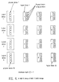
- FIG. 1 there is depicted a RAID 3 array of N DASDs according to the prior art.
- the blocks of a record are written in column major order with the Nth DASD always containing the parity block in the manner of the copending Brady et al application.
- the data rate is increased N-1 times the transfer rate of a single DASD and this configuration has found use where large read/writes are involved.
- the data rate would be N*the single DASD rate.
- the MTBF of the DASD array in figure 1 is much higher than that of each individual physical DASD.
- a RAID 3 array can continue to operate, it degraded mode, even after the failure of one of the individual DASDs that make up the array. This is because data on the failed DASD can be recreated from the data and parity on the remaining N-1 DASDs that have not failed.
- the array ordinarily operates in normal mode. When a DASD in the array has failed, the array operates in degraded mode. When the failed DASD is replaced with a spare, the array operates in rebuild mode until data has been completely rebuilt to the spare.
- Rebuilding typically proceeds in parallel with other user activity against the array, so the performance of the array in rebuild mode is worse than in normal or degraded modes. Note, that the performance of the RAID 3 array in degraded mode is no worse than in normal mode.
- FIG 2 there is shown a RAID 5 DASD array using block interleaving with one Kbyte blocks.
- the logical track has NK blocks of which (N-1)K blocks are data blocks and the remaining K blocks are parity blocks.
- N-1K blocks are data blocks
- the remaining K blocks are parity blocks.
- one logical track is shown.
- a predetermined number of logical tracks make up a logical cylinder.
- the invention to be subsequently described takes advantage of the principle involved in the ability to address a logical device (sometimes called a logical DASD) of multiple blocks, tracks and cylinders and map the addresses into real DASD array storage and vice versa.
- a logical device sometimes called a logical DASD
- the first Kbyte of data is stored entirely in the first block of DASD 1 (Block 1)
- the second Kbyte of data is stored entirely in the first block of DASD 2 (Block 2)
- the pattern of recording is variously termed column track layout or column major ordering of a logical array, since consecutive sequential blocks of the logical track are stored in columns. Note that the parity blocks are spread over the DASDs such that no one DASD contains all the parity blocks.
- FIG. 3 there is depicted another type of track layout for a RAID 5 DASD array.
- the array has N DASDs, K blocks per physical track, and NK blocks per logical track.
- consecutive blocks of the logical track are stored along a physical track (row order), as opposed to along the columns.
- RAID 5 array One of the major drawbacks of the RAID 5 array is that four acesses are required to update a single block. For example, in figure 3, updating Block 1 requires reading old values from Blocks 1 and N, calculating new parity by XORing old data, old parity and new data, then writing new data to Block 1 and new parity to Block N. The number of DASD accesses required to complete an update can potentially have a significant impact on the overall performance of RAID 5 arrays.
- a RAID 3 DASD array as the basic building block.
- 4 x 2.5" form factor DASDs are preferably physically packaged together to appear as a single logical device organized as a 3+P RAID 3 array.
- This logical device can also be packaged as a separate drawer (though this is not necessary) which would then be a fault-tolerant drawer.
- a write to such a logical device would cause the written block to be striped and written across 3 different DASD, and parity to be generated and simultaneously written to the fourth DASD which is the parity DASD.
- a single logical block is written as three physical blocks on three different DASD, so the logical block size is equal to 3 times the physical block size.
- FIG 4 there is set out a RAID 5 array organization of RAID 3 DASD arrays.
- an array hierarchy consisting of 4 logical devices organized as a RAID 5 array with an interleave depth of 1.
- reading or writing a single block only involves one logical device in the array.
- a single block write does not require reading old data, reading old parity, or writing new parity. It only involves writing new data to the one logical device involved in the update operation.
- a RAID 5 array of RAID 3 DASD arrays has attributes of both RAID 3 and RAID 5 arrays.
- the array hierarchy exhibits high performance on small requests and high data rate on large requests.
- the array hierarchy does not require four operations for write updates. Furthermore, its performance in degraded mode is the same as its performance in normal mode.
- a large access to a RAID 5 array of RAID 3 array, say to read L blocks starting at logical block X would work as follows. Use the steps described above to calculate device D and logical block within device LBD for each of the L blocks in the access. Access the L blocks as calculated.
- a spare logical device is used to facilitate rebuild in RAID 5 array of RAID 3 arrays.
- a physical device in a logical device is broken, data from the broken logical device is copied to the spare lgical device.
- This repair procedure is simpler than that for RAID 3 or RAID 5 arrays, since data can still be read or written to a broken lgical device.
- the rebuild procedure consists of reading all the other devices in the array, XORing corresponding blocks, then writing the resultant XORs to the spare device. Therefore, in RAID 3 and RAID 5 arrays, the rebuild procedure requires extra work of all the devices in the array.
- the rebuild procedure only involves the broken device and the spare device; all other devices are unaffected.
- CKD Counter-Key-Data
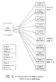
- FIG 7 there is shown a CKD RAID 5 array of RAID 3 arrays with an interleave depth of one track. It comprises a row at the top of the figure of RAID 3 CKD arrays (logical devices) 1 through 11. Logical tracks are shown as groups of rows underneath the counterpart logical device.
- CKD track 1 is stored on DASD 1, CKD track 2 on DASD 2, ..., CKD track 11 on DASD 11, CKD track 12 on DASD 1, and so on.
- the interleave depth is 1 track.
- CKD tracks 1 and 2 can both be on DASD 1
- CKD tracks 3 and 4 can both be on DASD 2, and so on.
- the CKD RAID 5 array of RAID 3 arrays as depicted in figure 7 preserves all of the advantages previously outlined for the general case. These are namely - simplicity, no reads before writes, high availability, high throughput on small requests, high bandwidth on small requests.
- the CKD RAID 5 array of RAID 3 arrays can be interleaved in units smaller than a track; such as a 1/4 track. That is 1/4th of a CKD track is on DASD 1, next 1/4th on DASD 2, and so on. This is subject to the restriction that records may now span logical device boundaries. This limitation would not occur upon interleave depths being limited to being multiples of full tracks.
- each DASD track extent is divided into a number of equal length sectors for addressing and rotary positioning sensing purposes.
- a CPU may use a virtual or real process for accessing an external storage subsystem termed a "channel” or "channel program” independent of other CPU activities.
- the channel access involves data locations ultimately mapped into a specific DASD, cylinder, track, track sector and head address of the external storage subsystem (DASD array).
- the storage model used in this invention maps logical tracks onto a RAID 5 array of logical devices in a pattern as prescribed above.
- a second mapping is made to the RAID 3 level DASDs. Adjustments in the mapping include a sector number offset in a channel program. Such an offset can be easily converted to a particular logical device number, where a given CKD record resides.
- the first and second extensions are discussed with respect to figures 5 and 6 and treat array hierarchies of dissimilar interleave depths and partitioned storage thereon.
- the third and fourth extensions incorporate figures 8 and 9 and treat logical devices distributed among physical devices clustered within the same power boundary and the rebuild of a failed DASD onto a spare.
- the last extension is a summary description of an array hierarchy of a RAID 5 array of RAID 5 DASD arrays.
- FIG. 5 there is shown a subsystem with 10 logical devices or RAID 3 DASD arrays organized as three RAID 5 of RAID 3 arrays (A, B, C).
- Array A includes four logical devices and an interleave depth of 1.
- Array B has three logical devices with an interleave depth of 4.
- array C attaches three logical devices and has an interleave depth of 10.
- Users of the storage subsystem would first define and create the different RAID 5 array of RAID 3 arrays. At array creation time, the users would specify the number of logical devices to be included in the array and the interleave depth and they would also specify a name for the array.
- the controller After creation of the dissimilar RAID 5 of RAID 3 array's, the controller accepts requests to read/write logical blocks within the created array. For each created RAID 5 of RAID 3 array, the array controller would need to save away in a table the actual logical devices involved in the RAID 5 array of RAID 3 arrays, the name of the array, and the interleave depth of the array. Such a table must be maintained in stable, non-volatile storage.
- RAID 5 of RAID 3 arrays do not consist of exactly some number of DASDs. That is, each RAID 3 array consists of fractions of DASDs.
- FIG 6 there is displayed a subsystem having with 6 logical devices. These are configured as follows:
- each of the RAID 5 of RAID 3 arrays may have a different interleave depth.
- the user specifies the array name, the interleave depth, the number of devices in the array and the number of logical blocks in the array. The last two parameters together determine the fraction of each DASD device that will be included in the DASD array.
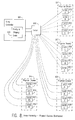
- an array controller 801 communicatively attaching a four drawer (four clusters) DASD array.
- the array includes logical devices (e.g. device A) formed from DASDs located in different physical DASD clusters e.g. 807, 817, 831, and 841.
- the communicative coupling occurs over a path including parity and striping logic 803, switch 805, and control and data links.
- the latter are shown as dotted line connections between switch 805 and each DASD in each of the physical clusters or drawers.
- logical device A comprises data DASDs 809, 819, 833 and parity DASD 843.
- logical device B includes data DASDs 811, 813, 821, and parity DASD 823.
- logical device C has the data DASDs 815, 825, 839 and parity DASD 849 while logical device D embraces data DASDs 835, 837, 845 and parity DASD 847.
- the DASDs of logical devices A and C are distributed to counterpart physical DASD clusters 807, 817, 831, and 841.
- the DASDs of logical device B are distributed only to clusters 807 and 817 and those of logical device D form part only of clusters 831 and 841.
- DASDs are usually physically grouped or clustered together in a mechanical and electrical packaging unit termed a "drawer".
- Each drawer has its own power and includes various electrical and mechanical plug connections which facilitate removal and replacement of DASDs individually.
- a drawer defines a power distribution as well as a packaging and servicing boundary.
- logic 803 segments the block and switch 805 establishes a path such that the first third is recorded on DASD 809 in cluster 807, the second third on DASD 819 in cluster 817, and the last third on DASD 833 in cluster 831. Parity over the segmented thirds is written to DASD 843 in cluster 841. Similarly, the segmenting and taking parity occurs when writing logical blocks to logical devices B, C, and D.
- a single spare logical device provides redundancy across multiple arrays.
- the failure of a physical device requires that logical blocks be copied from the broken logical device to the spare logical device.
- FIG 9 there is shown an array controller and DASD array hierarchy configuration similar to that depicted in figure 8 with the addition of a logical device reserved as a spare.
- the spare device is distributed as a spare DASD 917, 927, 939, and 951 in respective clusters 907, 919, 929, and 941.
- device B is formed from DASDs 911, 913, 923, and 925; device C includes DASDs 915, 926, 937, and 949; and device D comprises 933, 935, 945, and 947 variously distributed among the clusters.
- the last extension relates to the formation of an array hierarchy in which each logical device is a RAID 5 DASD array.
- a RAID 5 array of RAID 5 DASD arrays exploits the indirection inherent in the invention hierarchy by striping over RAID 5 arrays, the total data rate is not limited to that obtainable from any one array.
- the RAID 5 array of RAID 3 DASD arrays uses a RAID 3 array as a building block and stripes across the RAID 3 arrays. Similar to a RAID 5 array, the array hierarchy of this invention achieves high throughput on small requests and high bandwidth on large requests. Unlike RAID 5 arrays, in this invention, write updates do not require DASD accesses to read old data and old parity nor does it require DASD accesses to write new parity. Therefore, it does not have the four write penalty associated with RAID 5 arrays.
- the RAID 5 array of RAID 3 array is much simpler than a RAID 5 array to operate. For example, it does not have the problem of having to lock parity groups, as required by RAID 5, in order to maintain the consistency of parity groups in the face of concurrent updates. During degraded mode, when a physical device in the array is broken, the RAID 5 array of RAID 3 array suffers no loss in performance; it behaves like a RAID 3 array in this regard.
- rebuild in the array hierarchy of this invention is simpler than rebuilding either in RAID 3 or RAID 5 arrays, since it uses only the broken and spare devices and involves only a copy between them.
- rebuild involves ALL the other devices in the array and is more complex than copy.
- An additional benefit of a RAID 5 array of RAID 3 array is that devices need not be hot-pluggable. After data from the broken logical device is copied to a spare device, the physical devices in the broken logical device may all be powered off and repaired off-line.
Abstract
Described is a storage subsystem which takes the form of an array hierarchy comprising a plurality of RAID 3 arrays attached to a common control unit to form a RAID 5 array. Such a hierarchy achieves the concurrency of the RAID 5 array, and the bandwidth and degraded mode operation sustainable by a RAID 3 array. In the event of a DASD failure, the number of devices involved in rebuilding and re-writing missing data to a spare logical device is minimised. Also, disclosed is the accessing of variable length (CKD) records on the array hierarchy, an array hierarchy in which RAID 5 arrays have dissimilar number of logic devices (lower level RAID arrays) and interleave depths; the formation of logical arrays using fractional storage defined onto real DASD subsets; and the defining of logical devices onto DASDs distributed in the same or different physical clusters of DASDs and the rebuild operation thereof.
Description
- This invention relates to Direct Access Storage Device (DASD) array storage subsystems, and more particularly, to an array which provides for the efficient processing of large and small DASD array reads and writes in normal (fault tolerant), degraded, and rebuild modes.
-
RAID 3 designates a DASD array wherein data + parity are synchronously spread across N data + P parity DASDs. That is, the data is segmented and written (striped) across an array of at least N+P DASDs in column major order. This accords with the typology provided by Patterson et al, "A Case For Redundant Arrays Of Inexpensive Disks (RAID)", Report No. UCB/CSD 87/391, December 1987, Computer Science Division, U. of California, Berkeley. - The parity coding and striping of data across multiple DASDs and the rebuilding of data after a single DASD failure was introduced by Ouchi et al US Pat 4,092,732, "System for Recovering Data Stored in a Failed Memory Unit", issued 5/30/78. Also, replacement of a failed DASD by a formatted reserved spare "hot sparing" was described for a single parity domain by Arvin Park et al, "Providing Fault Tolerance In Parallel Secondary Storage Systems", Dept. Computer Science, Princeton University, Report CS-TR-057-86, Nov. 7, 1986. Likewise, dynamically configuring multiple parity domains and sharing of formatted spares across multiple domains was taught by Dunphy et al, US Pat 4,914,656, "Disk Drive Memory", issued 4/3/90.
- Because
RAID 3 arrays read and write parity coded segmented data to N+P DASDs synchronously, the data rate increases by N*single DASD rate. Also, the logical track size increases by N*single DASD track length. The P parity DASDs permits the array to continue operation even where one or more DASDs have failed (degraded mode). The failure limit is based on the properties of the parity coding and the on-fly-processing thereof, the amount of spare storage capacity, the time available to reconstitute missing data on the spare, the likelihood of multiple concurrent failures etc. Many arrays are premised on at most two non-nested DASD failures. - Increasing the number of DASDs decreases the mean time between array failure (MTBF). However, the use of redundancy such as parity coding and sparing increases the mean time between data unavailability because the system re-creates the missing data by recalculating it from the remaining data and/or rewriting it to a replacement DASD.
- In degraded mode where P = 1, if the parity DASD is the one that is unavailable, the data is nonetheless accessible, N blocks at a time, from the N data DASDs. If one of the data DASDs is the one that has failed, then it is necessary to rebuild the missing block from each referenced stripe or ordered segment set by logically combining the remaining blocks from the same stripe or set. Since this operation must be performed for each access, throughput is not reduced because recovery of a single parity or data block can be performed within the array controller on the fly. The risk of total array data unavailability should another failure occur while operating in degraded mode is not acceptable. The alternatives to permit array access where two or more failures occur are to parity encode data with P >= 2 or rebuild the data on a spare or replacement DASD.
- Where a formatted spare DASD is substituted for a failed DASD and data rebuilt and rewritten on said spare (rebuild mode), throughput returns to its normal rate. The array is said to change from a degraded to a normal (fault tolerant) mode. It should be noted that the rebuild and rewriting of the missing data onto a spare DASD may be done on a scheduled or opportunistic basis.
- Where up to two DASDs fail at the same time, the rebuild of the data requires use of more powerful coding methods and means such as the block parity coding disclosed and claimed in the copending European Application (application no. 92300586.2), "Method and Means for Encoding and Rebuilding Data Contents of Up to Two Unavailable DASDs in an Array of DASDs" (Inventor - Blaum), or US patent application, USSN 07/718,724, "Method and Means for Coding and Rebuilding the Data Contents of Unavailable DASDs or Rebuilding the Contents of One DASD in Error in the Presence of a Reduced Number of Unavailable DASDs in a DASD Array" (Inventors - Blaum and Roth, IBM Ref. SA9-91-038).
-
RAID 5 arrays distribute data and parity over a synchronized set of N DASDs. Patterson definesRAID 5 as merely recording parity on more than two DASDs in a synchronous DASD set. - For purposes of this invention,
RAID 5 DASD array is defined to be any DASD array accessible by a common control unit where concurrence of access and data rate are a trade-off function of the depth of interleaving. Interleave depth is in turn defined as the number of consecutive blocks of a logical track that are stored on a DASD before continuing with the next DASD in the array. - Alternatively, a
RAID 5 array is any N data + P parity DASD array in which a selectable interleave depth controls the striping and where P>=0. - An ample illustration is fully described it, European Application EP-A-458554, "Method and Means for Accessing Arrays With Tuned Data Transfer Rate and Concurrency" (Inventors - Brady et al.).
- For maximum concurrence, each DASD in an array of N would be accessed at the same time by a logically independent process. The data rate/process would be limited to that of a single DASD. This assumes that the data being referenced was written onto a counterpart DASD in row major order. On the other hand, for maximum data rate, all N DASDs would be accessed by one process. Relatedly, each logical record would be written in column major order.
- For completeness, column major order (sometimes called column track layout) has an interleave depth of 1. In contrast, row major order (sometimes called row track layout) exhibits an interleave depth equal to the number of blocks K in a DASD physical track.
- A CPU request to a storage subsystem (DASD array), which requires transferring large amounts of sequential data, is termed a "large request" or a "large transfer". A request for a small amount of data will be referred to as a "small request" or a "small transfer".
RAID 3 arrays are most efficient for large requests associated with numerically intensive computing and the like. In contrast,RAID 5 arrays can support small requests found with transaction processing via concurrency as where the interleave depth >= 2. Also,RAID 5 permits spreading data, parity, and spare capacity to balance workload/DASD, maintain high availability and DASD utilization with increased processing overhead. - Read requests involve positioning the access arms over the DASDs and copying data from the array usually to a buffer and sometimes checking the parity. Write requests and especially write update requests involve several operations. These include reading the old data + parity, calculating the new parity from the old data + new data + old parity, and writing back the new data + new parity. This involves at least two read and two write accesses per each write update.
- It can thus be seen that there are a number of disadvantages inherent in both
RAID 5 andRAID 3 arrays. For example,RAID 3 arrays do not permit a high level of concurrency andRAID 5 arrays suffer the performance hit of four accesses for each write update. What is required is an array configuration which provides the advantages of bothRAID 3 andRAID 5 arrays while avoiding or minimising their disadvantages. - Accordingly, the present invention provides in one aspect a storage subsystem comprising: a plurality of
RAID 3 arrays of direct access storage devices, eachRAID 3 array including N data + P parity DASDs attached to a local controller; a common control unit attached for communication to the plurality ofRAID 3 arrays to form aRAID 5 array of logical devices, each logical device comprising aRAID 3 array, theRAID 3 arrays being addressable through a path including the control unit and local controllers; and means including the control unit responsive to a data string formed from K*N blocks for segmenting the string into N blocks, encoding P parity blocks over each segment, and writing K of the N+P block segments in column major order of predetermined interleave depth on to counterpart logical devices. - In a second aspect of the invention there is provided a method for managing data transfer to a storage subsystem, said subsystem being formed from a plurality of
RAID 3 DASD arrays, eachRAID 3 array having N data + P parity DASDs attached to a controller, comprising the steps of: configuring the plurality ofRAID 3 DASD arrays into aRAID 5 array of addressable logical devices by communicatively attaching each of their controllers to a common control unit; segmenting a string of data at the common control unit in K logical records of N blocks each, parity coding each logical record and adding P blocks thereto, and writing K logical records of N+P blocks, each in column major order of predetermined interleave depth, onto theRAID 5 array of logical devices such that the N+P blocks of each logical record are recorded onto N+P DASDs of acounterpart RAID 3 array operating as the addressed logical device through a path including its controller. - Thus is provided a subsystem and method which is suited to the processing of large and small reads and writes and which provides the concurrency of a high level RAID array and the data rate of a low level RAID array.
- Using such a subsystem, the number of devices involved in rebuilding is minimised when the array is operating in degraded and rebuild modes.
- The invention may be extended to provide a subsystem in which arrays of dissimilar interleave depth may be accessed through a common path while preserving the concurrency and data rate and degraded and rebuild mode capabilities.
- In a preferred subsystem and method, the
RAID 5 array includes at least one spare logical device (when operating in normal mode). - Alternatively, the configuration step includes the formation of
logical RAID 3 arrays formed from no more than one DASD selected from each of N+P addressable failure independent DASD strings. - Where access is to be made of a logical device containing a failed DASD (degraded mode), the method includes concurrently accessing N+P-1 blocks from counterpart N+P-1 DASD. Advantageously, the rebuilding and rewriting of a spare logical device necessary to return to normal mode spans only the spare and the logical device containing the failed DASD.
- Embodiments of the invention will now be described, by way of example only, with reference to the accompanying drawings in which:
- Figure 1 shows a
RAID 3 DASD array according to the prior art tuned to handle large read and write requests. - Figures 2 and 3 depict a higher level RAID array also according to the prior art with logical blocks written in column major order and row major order respectively.
- Figure 4 sets forth a
RAID 5 array ofRAID 3 DASD arrays according to the invention. - Figure 5 articulates an attachment of
RAID 5 ofRAID 3 DASD arrays with dissimilar interleave depth of the blocks of logical records written thereon. - Figure 6 shows a further extension of figure 5 forming a
RAID 5 ofRAID 3 DASD arrays in the form of multiple fractional arrays. - Figure 7 illustrates the addressing pattern of the
RAID 5 array ofRAID 3 devices for variable length (CKD) formatted logical records. - Figure 8 shows an array hierarchy in which physical DASD resident in the same physical drawer are configurable into different logical devices coupling a common control unit.
- Figure 9 depicts the reconfiguration of the physical DASDs after a DASD failure and as a result of rebuilding the data resident on the failed DASD and writing the same to a spare DASD.
- Referring now to figure 1, there is depicted a
RAID 3 array of N DASDs according to the prior art. In this array, the blocks of a record are written in column major order with the Nth DASD always containing the parity block in the manner of the copending Brady et al application. Advantageously, the data rate is increased N-1 times the transfer rate of a single DASD and this configuration has found use where large read/writes are involved. Restated, if a logical record were written N+P blocks at a time to a synchronous array of N+P DASDs, the data rate would be N*the single DASD rate. - As previously mentioned, the MTBF of the DASD array in figure 1 is much higher than that of each individual physical DASD. As pointed out, a
RAID 3 array can continue to operate, it degraded mode, even after the failure of one of the individual DASDs that make up the array. This is because data on the failed DASD can be recreated from the data and parity on the remaining N-1 DASDs that have not failed. - The array ordinarily operates in normal mode. When a DASD in the array has failed, the array operates in degraded mode. When the failed DASD is replaced with a spare, the array operates in rebuild mode until data has been completely rebuilt to the spare.
- Rebuilding typically proceeds in parallel with other user activity against the array, so the performance of the array in rebuild mode is worse than in normal or degraded modes. Note, that the performance of the
RAID 3 array in degraded mode is no worse than in normal mode. - Referring now to figure 2, there is shown a
RAID 5 DASD array using block interleaving with one Kbyte blocks. For aRAID 5 array with N DASD and K blocks per physical track, the logical track has NK blocks of which (N-1)K blocks are data blocks and the remaining K blocks are parity blocks. In figure 2, one logical track is shown. A predetermined number of logical tracks make up a logical cylinder. The invention to be subsequently described takes advantage of the principle involved in the ability to address a logical device (sometimes called a logical DASD) of multiple blocks, tracks and cylinders and map the addresses into real DASD array storage and vice versa. - Referring again to figure 2, consider how the data in a logical track is stored. The first Kbyte of data is stored entirely in the first block of DASD 1 (Block 1), the second Kbyte of data is stored entirely in the first block of DASD 2 (Block 2), and so on. The pattern of recording is variously termed column track layout or column major ordering of a logical array, since consecutive sequential blocks of the logical track are stored in columns. Note that the parity blocks are spread over the DASDs such that no one DASD contains all the parity blocks.
- Now, accessing 1 Kbyte of data only requires access to one of the DASDs, and the other DASDs are free to handle other small transfers. As a result, a high degree of parallelism is possible for small transfers. At the same time, high data rate can be achieved on large transfers, since the data to be read or written on a large transfer is spread across the N DASDs, all of which may be read or written in parallel.
Referring now to figure 3, there is depicted another type of track layout for aRAID 5 DASD array. As before, the array has N DASDs, K blocks per physical track, and NK blocks per logical track. However, unlike column track layout, consecutive blocks of the logical track are stored along a physical track (row order), as opposed to along the columns. For the logical track shown in figure 3, (say Logical Track 1), all the parity is stored on the physical track of DASD N. Then, for Logical Track 2 (not shown in the figure), we would choose to store all the parity in DASD N-1, forLogical Track 3, all the parity would be stored in DASD N-2, and so on. Thus, as for column track layout, the parity is spread among all the DASDs, and there is no one single parity DASD. - One of the major drawbacks of the
RAID 5 array is that four acesses are required to update a single block. For example, in figure 3, updatingBlock 1 requires reading old values fromBlocks 1 and N, calculating new parity by XORing old data, old parity and new data, then writing new data to Block 1 and new parity to Block N. The number of DASD accesses required to complete an update can potentially have a significant impact on the overall performance ofRAID 5 arrays. - Referring now to figure 4, there is shown a
RAID 3 DASD array as the basic building block. For example, 4 x 2.5" form factor DASDs (physical devices) are preferably physically packaged together to appear as a single logical device organized as a 3+P RAID 3 array. This logical device can also be packaged as a separate drawer (though this is not necessary) which would then be a fault-tolerant drawer. A write to such a logical device would cause the written block to be striped and written across 3 different DASD, and parity to be generated and simultaneously written to the fourth DASD which is the parity DASD. A single logical block is written as three physical blocks on three different DASD, so the logical block size is equal to 3 times the physical block size. - Referring again to figure 4, there is set out a
RAID 5 array organization ofRAID 3 DASD arrays. In figure 4, there is shown an array hierarchy consisting of 4 logical devices organized as aRAID 5 array with an interleave depth of 1. In this configuration, reading or writing a single block only involves one logical device in the array. Unlike aRAID 5 DASD array, a single block write does not require reading old data, reading old parity, or writing new parity. It only involves writing new data to the one logical device involved in the update operation. - A
RAID 5 array ofRAID 3 DASD arrays has attributes of bothRAID 3 andRAID 5 arrays. In a manner similar to aRAID 5 array, the array hierarchy exhibits high performance on small requests and high data rate on large requests. In a manner similar to aRAID 3 array, the array hierarchy does not require four operations for write updates. Furthermore, its performance in degraded mode is the same as its performance in normal mode. - Turning now to a description of normal mode accessing for a
RAID 5 array ofRAID 3 DASD arrays, consider aRAID 5 array ofRAID 3 array with the following parameters:


The following steps describes the method used to access logical block X in theRAID 5 array ofRAID 3 array. - (1) Calculate B as X/(I*N)
- (2) Calculate R as 1 + module (X-1)/(I*N)
- (3) Calculate device D as ceil(R/I)
- (4) Calculate logical block within device LBD as 1 + modulo (R-1)/I + B*I
- (5) Access logical block LBD in logical device D. For a write, this involves writing the data to three physical blocks and the parity to a fourth physical block. For a read this involves reading three physical blocks.
- Referring again to figure 4, in this array, I=1 and N=4. Consider a request to access logical block 6 (i.e X=6). Then,

Logical Block within Device LBD = 2. So,logical block 6 really the second logical block onlogical device 2. - A large access to a
RAID 5 array ofRAID 3 array, say to read L blocks starting at logical block X would work as follows. Use the steps described above to calculate device D and logical block within device LBD for each of the L blocks in the access. Access the L blocks as calculated. - Next will be described a method for making a small access to the array hierarchy when operating in degraded mode. From this, the method for large access is then immediately apparent.
- (1) Calculate device D and logical block within device LBD as during normal mode.
- (2) Execute a read of a logical block by:
- (a) If the three physical data devices on the designated logical device D are all available, read three physical blocks from the three devices and return logical block.
- (b) If one of the physical devices in logical device D is broken, and it happens to be one of the three data devices, then read the two available physical data blocks and the available parity block. Use the parity block to calculate the value of the missing data block, thus creating the entire logical data block.
- (3) Execute a write of a logical block by:
- (a) If all four physical devices in D are available, then proceed as in normal mode; that is, split the logical block into thirds, write each third to a different physical device and the XOR of the thirds into the parity block.
- (b) If the parity physical device is broken, then split the logical block into thirds and write each third to a different physical device.
- (c) If one of the three data physical devices is broken, split the logical block into thirds, write two of these three to the two available devices, then write the XOR of the three thirds to the parity device.
- A spare logical device is used to facilitate rebuild in
RAID 5 array ofRAID 3 arrays. When a physical device in a logical device is broken, data from the broken logical device is copied to the spare lgical device. This repair procedure is simpler than that forRAID 3 orRAID 5 arrays, since data can still be read or written to a broken lgical device. InRAID 3 andRAID 5 arrays, the rebuild procedure consists of reading all the other devices in the array, XORing corresponding blocks, then writing the resultant XORs to the spare device. Therefore, inRAID 3 andRAID 5 arrays, the rebuild procedure requires extra work of all the devices in the array. In aRAID 5 array ofRAID 3 array, the rebuild procedure only involves the broken device and the spare device; all other devices are unaffected. - Referring again to figure 4 and assuming that one of the DASDs in
logical device 2 has just failed , then the recovery algorithmically involves: - Let N:
- = the number of logical devices from 1, 2, 3,. . N
- T:
- = the number of tracks per DASD
- DO i:
- = 1 to N
- Up to this point, the accessed data structures for the
RAID 5 array ofRAID 3 arrays have been blocks formatted on DASDs in fixed-block extents only. However, one extension of this invention involves modification of theRAID 5 array ofRAID 3 arrays in which the DASDs are formatted in variable length extent according to the well known Count-Key-Data (CKD) convention.
Referring now to figure 7, there is shown aCKD RAID 5 array ofRAID 3 arrays with an interleave depth of one track. It comprises a row at the top of the figure ofRAID 3 CKD arrays (logical devices) 1 through 11. Logical tracks are shown as groups of rows underneath the counterpart logical device. - The CKD track on each
RAID 3 logical device is laid out as follows: - (a) every count field is replicated on the 3 physical data devices of the logical device;
- (b) every key and data field is split three ways, with each third being stored on one of the three physical data devices;
- (c) the parity track has the same number of fields as the corresponding three data tracks, each field being the XOR of the corresponding three fields from the three data tracks.
- Referring again to figure 7,
CKD track 1 is stored onDASD 1,CKD track 2 onDASD 2, ...,CKD track 11 onDASD 11,CKD track 12 onDASD 1, and so on. Thus, the interleave depth is 1 track. With this layout, a request to read 12 or more tracks together, would be processed at the maximum data rate. It should be readily obvious to the careful reader that interleave depths of multiples of a track can also be easily accommodated. So, CKD tracks 1 and 2 can both be onDASD 1, CKD tracks 3 and 4 can both be onDASD 2, and so on. - The
CKD RAID 5 array ofRAID 3 arrays as depicted in figure 7 preserves all of the advantages previously outlined for the general case. These are namely - simplicity, no reads before writes, high availability, high throughput on small requests, high bandwidth on small requests. - In another embodiment the
CKD RAID 5 array ofRAID 3 arrays can be interleaved in units smaller than a track; such as a 1/4 track. That is 1/4th of a CKD track is onDASD 1, next 1/4th onDASD 2, and so on. This is subject to the restriction that records may now span logical device boundaries. This limitation would not occur upon interleave depths being limited to being multiples of full tracks. - As may be recalled, each DASD track extent is divided into a number of equal length sectors for addressing and rotary positioning sensing purposes. As described in Luiz et al, US Pat. 4,207,609, "Method and Means for Path Independent Device Reservation and Reconnection in a Multi-CPU and Shared Device Access System", issued Jun. 10, 1980, a CPU may use a virtual or real process for accessing an external storage subsystem termed a "channel" or "channel program" independent of other CPU activities. The channel access involves data locations ultimately mapped into a specific DASD, cylinder, track, track sector and head address of the external storage subsystem (DASD array).
- The storage model used in this invention maps logical tracks onto a
RAID 5 array of logical devices in a pattern as prescribed above. A second mapping is made to theRAID 3 level DASDs. Adjustments in the mapping include a sector number offset in a channel program. Such an offset can be easily converted to a particular logical device number, where a given CKD record resides. - As an example of the use of sector number offset, consider the fact that offsets less than 1/4th of a rotation would map to
logical device 1, offsets between a 1/4 and 1/2 a rotation would map tological device 2, and so on. Reading of a record would presumptively start from that logical device. If the record continues or spans the next logical device, then reading would continue from the next logical device, and so on. This is managed in a manner similar to the processing of overflow CKD records in prior DASD storage subsystems. - There are five extensions which embody the principles of this invention. The first and second extensions are discussed with respect to figures 5 and 6 and treat array hierarchies of dissimilar interleave depths and partitioned storage thereon. The third and fourth extensions incorporate figures 8 and 9 and treat logical devices distributed among physical devices clustered within the same power boundary and the rebuild of a failed DASD onto a spare. The last extension is a summary description of an array hierarchy of a
RAID 5 array ofRAID 5 DASD arrays. - Referring now to figure 5, there is shown a subsystem with 10 logical devices or
RAID 3 DASD arrays organized as threeRAID 5 ofRAID 3 arrays (A, B, C). Array A includes four logical devices and an interleave depth of 1. Array B has three logical devices with an interleave depth of 4. Lastly, array C attaches three logical devices and has an interleave depth of 10. Users of the storage subsystem would first define and create thedifferent RAID 5 array ofRAID 3 arrays. At array creation time, the users would specify the number of logical devices to be included in the array and the interleave depth and they would also specify a name for the array. - After creation of the
dissimilar RAID 5 ofRAID 3 array's, the controller accepts requests to read/write logical blocks within the created array. For each createdRAID 5 ofRAID 3 array, the array controller would need to save away in a table the actual logical devices involved in theRAID 5 array ofRAID 3 arrays, the name of the array, and the interleave depth of the array. Such a table must be maintained in stable, non-volatile storage. - Referring again to figure 6, there is set forth an embodiment in which
RAID 5 ofRAID 3 arrays do not consist of exactly some number of DASDs. That is, eachRAID 3 array consists of fractions of DASDs. As an example, in figure 6, there is displayed a subsystem having with 6 logical devices. These are configured as follows: - (1) Array A is constructed from 1/2 of
logical devices 1 through 6, - (2) Array B from half of
logical devices 1 through 3, and - (3) Array C from 1/2 of
logical devices 4 through 6. - As before, each of the
RAID 5 ofRAID 3 arrays may have a different interleave depth. At array creation time, the user specifies the array name, the interleave depth, the number of devices in the array and the number of logical blocks in the array. The last two parameters together determine the fraction of each DASD device that will be included in the DASD array. - Referring now to figure 8, there is shown an
array controller 801 communicatively attaching a four drawer (four clusters) DASD array. The array includes logical devices (e.g. device A) formed from DASDs located in different physical DASD clusters e.g. 807, 817, 831, and 841. The communicative coupling occurs over a path including parity andstriping logic 803,switch 805, and control and data links. The latter are shown as dotted line connections betweenswitch 805 and each DASD in each of the physical clusters or drawers. - Referring again to figure 8, logical device A comprises
data DASDs parity DASD 843. Likewise, logical device B includesdata DASDs data DASDs 815, 825, 839 and parity DASD 849 while logical device D embracesdata DASDs parity DASD 847. - It should be noted that the DASDs of logical devices A and C are distributed to counterpart
physical DASD clusters clusters clusters 831 and 841. - As should be appreciated for array purposes, DASDs are usually physically grouped or clustered together in a mechanical and electrical packaging unit termed a "drawer". Each drawer has its own power and includes various electrical and mechanical plug connections which facilitate removal and replacement of DASDs individually. A drawer defines a power distribution as well as a packaging and servicing boundary.
- When a logical block is to be written to say logical device A,
logic 803 segments the block and switch 805 establishes a path such that the first third is recorded onDASD 809 incluster 807, the second third onDASD 819 incluster 817, and the last third onDASD 833 in cluster 831. Parity over the segmented thirds is written toDASD 843 incluster 841. Similarly, the segmenting and taking parity occurs when writing logical blocks to logical devices B, C, and D. - With respect to sparing and rebuild activities, a single spare logical device provides redundancy across multiple arrays. The failure of a physical device requires that logical blocks be copied from the broken logical device to the spare logical device.
- Referring now to figure 9, there is shown an array controller and DASD array hierarchy configuration similar to that depicted in figure 8 with the addition of a logical device reserved as a spare. The spare device is distributed as a
spare DASD respective clusters - Suppose
DASD 909 of logical device A and residing incluster 907 fails. The sparing and rebuild algorithm is simply that of - (a) reading from the remaining
DASDs paths including switch 905, - (b) logically combining the three segments of each block to reconstitute the
fourth segment logic 903, - (c) writing the four segments to
counterpart DASDs - (d) substituting the address of the spare for that of device A in the pathing or address tables,
- (e) changing
DASDs - (f) replacing failed
DASD 909 opportunistically with another DASD to complete the augmentation of the spare device, thereby returning the array hierarchy to normal operating mode. - For completeness in figure 9, device B is formed from
DASDs DASDs - The last extension relates to the formation of an array hierarchy in which each logical device is a
RAID 5 DASD array. ARAID 5 array ofRAID 5 DASD arrays exploits the indirection inherent in the invention hierarchy by striping overRAID 5 arrays, the total data rate is not limited to that obtainable from any one array. - To summarise, the
RAID 5 array ofRAID 3 DASD arrays uses aRAID 3 array as a building block and stripes across theRAID 3 arrays. Similar to aRAID 5 array, the array hierarchy of this invention achieves high throughput on small requests and high bandwidth on large requests. UnlikeRAID 5 arrays, in this invention, write updates do not require DASD accesses to read old data and old parity nor does it require DASD accesses to write new parity. Therefore, it does not have the four write penalty associated withRAID 5 arrays. - Additionally, the
RAID 5 array ofRAID 3 array is much simpler than aRAID 5 array to operate. For example, it does not have the problem of having to lock parity groups, as required byRAID 5, in order to maintain the consistency of parity groups in the face of concurrent updates. During degraded mode, when a physical device in the array is broken, theRAID 5 array ofRAID 3 array suffers no loss in performance; it behaves like aRAID 3 array in this regard. - Finally, rebuild in the array hierarchy of this invention is simpler than rebuilding either in
RAID 3 orRAID 5 arrays, since it uses only the broken and spare devices and involves only a copy between them. In theprior art RAID 3 orRAID 5 arrays, rebuild involves ALL the other devices in the array and is more complex than copy. An additional benefit of aRAID 5 array ofRAID 3 array is that devices need not be hot-pluggable. After data from the broken logical device is copied to a spare device, the physical devices in the broken logical device may all be powered off and repaired off-line.
WRITE track i to spare logical device;
END DO
CHANGE path connection tables such that all references to
ISOLATE old
Claims (13)
- A storage subsystem comprising:
a plurality of RAID 3 arrays of direct access storage devices (DASDs), each RAID 3 array including N data + P parity DASDs attached to a local controller;
a common control unit attached for communication to the plurality of RAID 3 arrays to form a RAID 5 array of logical devices, each logical device comprising a RAID 3 array, the RAID 3 arrays being addressable through a path including the control unit and local controllers; and
means including the control unit responsive to a data string formed from K*N blocks for segmenting the string into N blocks, encoding P parity blocks over each segment, and writing K of the N+P block segments in column major order of predetermined interleave depth on to counterpart logical devices. - A storage subsystem as claimed in claim 1, wherein said segmenting, encoding, and writing means further includes means for recording the N+P blocks of each logical device onto N+P DASDs of a counterpart RAID 3 array through a path including its controller.
- A storage subsystem as claimed in claim 2, wherein the control unit is attached to a subset of the plurality of devices to form a RAID 5 array of logical devices, others of the plurality being reserved as spare devices; the subsystem further comprising:
second means including the control unit for detecting a DASD failure in the RAID 3 DASD array counterpart of a logical device and for writing to the logical devices in the designated order and depth and recording the blocks but for those blocks destined for the failed DASD; and
third means for rebuilding and rewriting N+P DASDs of the logical device whose counterpart RAID 3 array contains the failed DASD onto the spare device on either a predetermined or opportunistic schedule, said rebuild and rewrite spanning only the spare device and said device having the failed DASD. - A storage subsystem as claimed in claim 3, wherein
the plurality of RAID 3 arrays further comprises a first RAID 5 array of m logic devices and a second RAID 5 array of n logic devices, m not equal to n;
the control unit further comprises means for switchably coupling the control unit to any one of the RAID 5 arrays; and
the first means including the switching means further comprises means for selecting any of the RAID 5 arrays and recording segments on the logic devices thereof in column major order thereon to an interleave depth distinguishable from the interleave depth of at least one other RAID 5 array. - A storage subsystem comprising:
a plurality of logical devices, each device formed from a RAID 3 array of DASDs;
a control unit for communicatively attaching either a first or a second RAID 5 array of the logical devices;
first means including the control unit for selecting the first RAID 5 array, segmenting a data string into segments of m data blocks, coding p parity blocks over each segment, and writing each segment of m data + p parity blocks across the logical devices of the first array in column major order to a first interleave depth; and
second means including the control unit for selecting the second RAID 5 array, segmenting another data string into n data blocks, coding p parity blocks over each segment, and writing each segment of n data + p parity blocks across the second DASD subset in column major order to a second interleave depth, at least one of the devices of the second RAID 5 array being also a member of the first RAID 5 array. - A storage subsystem as claimed in claim 5, wherein at least one logical device DASD of the plurality reserves a fraction of its storage capacity to the first and the second RAID 5 arrays proportional to the number of logical devices in each RAID 5 array.
- A storage subsystem as claimed in claim 6, wherein n is not equal to m, and the second depth is not equal to the first depth.
- A method for writing data to and from a plurality of DASDs, comprising the steps of:
configuring the plurality of DASDs into a RAID 5 array of logical devices, each logical device including N data + P parity DASDs configured as a RAID 3 DASD array; and
segmenting each data string into K logical records of N data blocks each, coding P parity blocks over each segmented record, and writing the K logical records in column major order of predetermined interleave depth onto the logical devices of the RAID 5 array. - A method for managing data transfer to a storage subsystem, said subsystem being formed from a plurality of RAID 3 DASD arrays, each RAID 3 array having N data + P parity DASDs attached to a controller, comprising the steps of:
configuring the plurality of RAID 3 DASD arrays into a RAID 5 array of addressable logical devices by communicatively attaching each of their controllers through a common control unit ; and
segmenting a string of data at the common control unit into K logical records of N blocks each, parity coding each logical record and adding P blocks thereto, and
writing K logical records of N+P blocks, each in column major order of predetermined interleave depth, onto the RAID 5 array of logical devices such that the N+P blocks of each logical record are recorded onto N+P DASDs of a counterpart RAID 3 array operating as the addressed logical device through a path including its controller. - A method as claimed in claim 9, further comprising: reserving at least one of the logical devices as a spare device during the configuring step;
accessing the logical devices, other than the spare device, through a path including the common control unit in column major order of predetermined interleaved depth;
detecting a DASD failure in a RAID 3 array;
responsive to detection of said failure, accessing the logical devices except for the failed DASD; and
rebuilding and rewriting N+P DASDs of the logical device whose counterpart RAID 3 array contains the failed DASD onto a spare device on either a predetermined or opportunistic schedule, said rebuild and rewrite spanning only the spare device and said device having the failed DASD. - A method as claimed in claim 10, wherein the accessing step further comprises:
accessing K*(N+P) blocks from the array in row major order K modulo M and in column major order K module M*(N+P), M lying in the closed integer interval (1,K); and
executing large and small access requests over the RAID 5 array such that a minimum number X of blocks transferred to achieve the maximum data rate for a given M lies in the closed interval ((N+P-1, (N+P-1)*K) whose end points are defined by M=1 and M=K respectively. - A method as claimed in claim 10 or claim 11, wherein the step of accessing all but the failed DASD in the RAID 3 array of an accessed logical device responsive to a small read access further includes:
reading all but the failed DASD and reconstructing any unavailable data block by logically combining the N+P-1 available blocks; and
writing to all but the failed DASD such that the parity block and all but one of the data blocks are stored on the remaining DASDs of RAID 3 array of the accessed device. - A method for writing variable length count-key-data (CKD) field formatted records to a storage subsystem, said subsystem being formed from a plurality of RAID 3 DASD arrays, each RAID 3 array having N data + P parity DASDs attaching a controller, comprising the steps of:
configuring the plurality of RAID 3 DASD arrays into a RAID 5 array of addressable logical devices by communicatively attaching each of their controllers through a common control unit ; and
segmenting each data string at the common control unit into K logical records of N stripes each, parity coding each logical record and adding P strings thereto, and
writing K logical records of N+P strings, each in row major order of predetermined interleave depth, onto the RAID 5 array of logical devices such that the N+P strings of each logical record are recorded onto N+P DASDs of a counterpart RAID 3 array operating as the addressed logical device through a path including its controller such that:
each count field of a CKD formatted variable length record being replicated on the N DASDs of the first device in row major order,
the key and data fields following the count field of a CKD formatted variable length record are segmented and recorded across N DASDs of the counterpart RAID 3 array operating as the addressed logical device in the predetermined row major order and interleave depth, and
each parity block P logically combining a counterpart N fields.
Applications Claiming Priority (2)
| Application Number | Priority Date | Filing Date | Title |
|---|---|---|---|
| US07/725,696 US5301297A (en) | 1991-07-03 | 1991-07-03 | Method and means for managing RAID 5 DASD arrays having RAID DASD arrays as logical devices thereof |
| US725696 | 1991-07-03 |
Publications (2)
| Publication Number | Publication Date |
|---|---|
| EP0521630A2 true EP0521630A2 (en) | 1993-01-07 |
| EP0521630A3 EP0521630A3 (en) | 1994-02-16 |
Family
ID=24915608
Family Applications (1)
| Application Number | Title | Priority Date | Filing Date |
|---|---|---|---|
| EP92305513A Withdrawn EP0521630A2 (en) | 1991-07-03 | 1992-06-16 | DASD array hierarchies |
Country Status (3)
| Country | Link |
|---|---|
| US (1) | US5301297A (en) |
| EP (1) | EP0521630A2 (en) |
| JP (1) | JPH0731579B2 (en) |
Cited By (11)
| Publication number | Priority date | Publication date | Assignee | Title |
|---|---|---|---|---|
| EP0701198A1 (en) * | 1994-05-19 | 1996-03-13 | Starlight Networks, Inc. | Method for operating an array of storage units |
| US5566316A (en) * | 1994-02-10 | 1996-10-15 | Storage Technology Corporation | Method and apparatus for hierarchical management of data storage elements in an array storage device |
| WO1997033224A1 (en) * | 1996-03-07 | 1997-09-12 | Philips Electronics N.V. | Multiple disk drive array with plural parity groups |
| US5721950A (en) * | 1992-11-17 | 1998-02-24 | Starlight Networks | Method for scheduling I/O transactions for video data storage unit to maintain continuity of number of video streams which is limited by number of I/O transactions |
| US5802394A (en) * | 1994-06-06 | 1998-09-01 | Starlight Networks, Inc. | Method for accessing one or more streams in a video storage system using multiple queues and maintaining continuity thereof |
| EP1107582A2 (en) * | 1999-12-08 | 2001-06-13 | Sony Corporation | Data recording and reproducing apparatus and methods |
| WO2010026366A1 (en) * | 2008-09-02 | 2010-03-11 | Extas Global Ltd. | Distributed storage and communication |
| WO2010080696A1 (en) * | 2009-01-09 | 2010-07-15 | Netapp, Inc. | System and method for redundancy-protected aggregates |
| EP1327936B1 (en) * | 2001-12-28 | 2011-08-03 | Network Appliance, Inc. | Correcting multiple block data loss in a storage array using a combination of a single diagonal parity group and multiple row parity groups |
| CN109857584A (en) * | 2017-11-30 | 2019-06-07 | 慧荣科技股份有限公司 | It accesses method, memory storage and its controller of control in memory storage |
| US10691543B2 (en) | 2017-11-14 | 2020-06-23 | International Business Machines Corporation | Machine learning to enhance redundant array of independent disks rebuilds |
Families Citing this family (114)
| Publication number | Priority date | Publication date | Assignee | Title |
|---|---|---|---|---|
| JP2603757B2 (en) * | 1990-11-30 | 1997-04-23 | 富士通株式会社 | Method of controlling array disk device |
| JP2913917B2 (en) * | 1991-08-20 | 1999-06-28 | 株式会社日立製作所 | Storage device and storage device system |
| JP2550239B2 (en) * | 1991-09-12 | 1996-11-06 | 株式会社日立製作所 | External storage system |
| US5974544A (en) * | 1991-12-17 | 1999-10-26 | Dell Usa, L.P. | Method and controller for defect tracking in a redundant array |
| JP3160106B2 (en) * | 1991-12-23 | 2001-04-23 | ヒュンダイ エレクトロニクス アメリカ | How to sort disk arrays |
| US5526507A (en) * | 1992-01-06 | 1996-06-11 | Hill; Andrew J. W. | Computer memory array control for accessing different memory banks simullaneously |
| US5745789A (en) * | 1992-01-23 | 1998-04-28 | Hitachi, Ltd. | Disc system for holding data in a form of a plurality of data blocks dispersed in a plurality of disc units connected by a common data bus |
| US5418921A (en) * | 1992-05-05 | 1995-05-23 | International Business Machines Corporation | Method and means for fast writing data to LRU cached based DASD arrays under diverse fault tolerant modes |
| US5734926A (en) * | 1992-07-15 | 1998-03-31 | Advanced Hardware Architectures | Direct memory access controller in an integrated circuit |
| US5488694A (en) * | 1992-08-28 | 1996-01-30 | Maspar Computer Company | Broadcasting headers to configure physical devices interfacing a data bus with a logical assignment and to effect block data transfers between the configured logical devices |
| US5857112A (en) * | 1992-09-09 | 1999-01-05 | Hashemi; Ebrahim | System for achieving enhanced performance and data availability in a unified redundant array of disk drives by using user defined partitioning and level of redundancy |
| US5459853A (en) * | 1992-11-23 | 1995-10-17 | International Business Machines Corporation | Efficient variable-block data storage system employing a staggered fixed-block-architecture array |
| US5519849A (en) * | 1992-12-07 | 1996-05-21 | Digital Equipment Corporation | Method of reducing the complexity of an I/O request to a RAID-4 or RAID-5 array |
| US5579474A (en) * | 1992-12-28 | 1996-11-26 | Hitachi, Ltd. | Disk array system and its control method |
| US5845329A (en) * | 1993-01-29 | 1998-12-01 | Sanyo Electric Co., Ltd. | Parallel computer |
| US6138126A (en) * | 1995-05-31 | 2000-10-24 | Network Appliance, Inc. | Method for allocating files in a file system integrated with a raid disk sub-system |
| US5598549A (en) * | 1993-06-11 | 1997-01-28 | At&T Global Information Solutions Company | Array storage system for returning an I/O complete signal to a virtual I/O daemon that is separated from software array driver and physical device driver |
| US5510905A (en) * | 1993-09-28 | 1996-04-23 | Birk; Yitzhak | Video storage server using track-pairing |
| JP2912802B2 (en) * | 1993-10-14 | 1999-06-28 | 富士通株式会社 | Disk array device failure handling method and device |
| US5632012A (en) * | 1993-11-24 | 1997-05-20 | Storage Technology Corporation | Disk scrubbing system |
| DE69418984T2 (en) * | 1993-11-30 | 2000-01-27 | Hitachi Ltd | Storage disk arrangement with storage disks distributed on a plurality of printed circuit boards which remain accessible when a part of the printed circuit boards is removed |
| US5485571A (en) * | 1993-12-23 | 1996-01-16 | International Business Machines Corporation | Method and apparatus for providing distributed sparing with uniform workload distribution in failures |
| US5499253A (en) * | 1994-01-05 | 1996-03-12 | Digital Equipment Corporation | System and method for calculating RAID 6 check codes |
| US5463643A (en) * | 1994-03-07 | 1995-10-31 | Dell Usa, L.P. | Redundant memory channel array configuration with data striping and error correction capabilities |
| US5546558A (en) * | 1994-06-07 | 1996-08-13 | Hewlett-Packard Company | Memory system with hierarchic disk array and memory map store for persistent storage of virtual mapping information |
| DE69533764T2 (en) * | 1994-06-22 | 2005-12-01 | Hewlett-Packard Development Co., L.P., Houston | A method of using different content storage disks in a single volume of a hierarchical disk array |
| US5479653A (en) * | 1994-07-14 | 1995-12-26 | Dellusa, L.P. | Disk array apparatus and method which supports compound raid configurations and spareless hot sparing |
| US5657439A (en) * | 1994-08-23 | 1997-08-12 | International Business Machines Corporation | Distributed subsystem sparing |
| US5524204A (en) * | 1994-11-03 | 1996-06-04 | International Business Machines Corporation | Method and apparatus for dynamically expanding a redundant array of disk drives |
| US5488701A (en) * | 1994-11-17 | 1996-01-30 | International Business Machines Corporation | In log sparing for log structured arrays |
| US5659704A (en) * | 1994-12-02 | 1997-08-19 | Hewlett-Packard Company | Methods and system for reserving storage space for data migration in a redundant hierarchic data storage system by dynamically computing maximum storage space for mirror redundancy |
| JPH08249133A (en) * | 1994-12-15 | 1996-09-27 | Internatl Business Mach Corp <Ibm> | Method and system for measures against fault of disk drive array |
| US5613085A (en) * | 1994-12-27 | 1997-03-18 | International Business Machines Corporation | System for parallel striping of multiple ordered data strings onto a multi-unit DASD array for improved read and write parallelism |
| US5671439A (en) * | 1995-01-10 | 1997-09-23 | Micron Electronics, Inc. | Multi-drive virtual mass storage device and method of operating same |
| US5666512A (en) * | 1995-02-10 | 1997-09-09 | Hewlett-Packard Company | Disk array having hot spare resources and methods for using hot spare resources to store user data |
| US5574882A (en) * | 1995-03-03 | 1996-11-12 | International Business Machines Corporation | System and method for identifying inconsistent parity in an array of storage |
| US5845319A (en) * | 1995-08-23 | 1998-12-01 | Fujitsu Limited | Disk array device which separates local and physical disks using striping and operation mode selection |
| WO1997011426A1 (en) | 1995-09-18 | 1997-03-27 | Cyberstorage Systems, Inc. | Universal storage management system |
| US5774643A (en) * | 1995-10-13 | 1998-06-30 | Digital Equipment Corporation | Enhanced raid write hole protection and recovery |
| US5933592A (en) * | 1995-10-13 | 1999-08-03 | Digital Equipment Corporation | Promoting device level error to raidset level error to restore redundacy in a raid array data storage system |
| US5826001A (en) * | 1995-10-13 | 1998-10-20 | Digital Equipment Corporation | Reconstructing data blocks in a raid array data storage system having storage device metadata and raid set metadata |
| US5862312A (en) * | 1995-10-24 | 1999-01-19 | Seachange Technology, Inc. | Loosely coupled mass storage computer cluster |
| US6449730B2 (en) | 1995-10-24 | 2002-09-10 | Seachange Technology, Inc. | Loosely coupled mass storage computer cluster |
| JP3776496B2 (en) * | 1996-01-17 | 2006-05-17 | 株式会社日立製作所 | Data storage system |
| US5727181A (en) * | 1996-02-14 | 1998-03-10 | International Business Machines Corporation | Array management system with volume transform filter |
| US5758050A (en) * | 1996-03-12 | 1998-05-26 | International Business Machines Corporation | Reconfigurable data storage system |
| US5819310A (en) * | 1996-05-24 | 1998-10-06 | Emc Corporation | Method and apparatus for reading data from mirrored logical volumes on physical disk drives |
| US6108812A (en) * | 1996-06-20 | 2000-08-22 | Lsi Logic Corporation | Target device XOR engine |
| US5960169A (en) * | 1997-02-27 | 1999-09-28 | International Business Machines Corporation | Transformational raid for hierarchical storage management system |
| US5951691A (en) * | 1997-05-16 | 1999-09-14 | International Business Machines Corporation | Method and system for detection and reconstruction of corrupted data in a data storage subsystem |
| US5933840A (en) * | 1997-05-19 | 1999-08-03 | International Business Machines Corporation | Garbage collection in log-structured information storage systems using age threshold selection of segments |
| US6112255A (en) * | 1997-11-13 | 2000-08-29 | International Business Machines Corporation | Method and means for managing disk drive level logic and buffer modified access paths for enhanced raid array data rebuild and write update operations |
| US6240413B1 (en) * | 1997-12-22 | 2001-05-29 | Sun Microsystems, Inc. | Fine-grained consistency mechanism for optimistic concurrency control using lock groups |
| US6360223B1 (en) | 1997-12-22 | 2002-03-19 | Sun Microsystems, Inc. | Rule-based approach to object-relational mapping strategies |
| US6268850B1 (en) | 1997-12-22 | 2001-07-31 | Sun Microsystems, Inc. | User interface for the specification of lock groups |
| US6385618B1 (en) | 1997-12-22 | 2002-05-07 | Sun Microsystems, Inc. | Integrating both modifications to an object model and modifications to a database into source code by an object-relational mapping tool |
| US6175837B1 (en) | 1998-06-29 | 2001-01-16 | Sun Microsystems, Inc. | Object-relational mapping toll that processes views |
| US6374256B1 (en) | 1997-12-22 | 2002-04-16 | Sun Microsystems, Inc. | Method and apparatus for creating indexes in a relational database corresponding to classes in an object-oriented application |
| US6052799A (en) * | 1998-05-15 | 2000-04-18 | International Business Machines Corporation | System and method for recovering a directory for a log structured array |
| US6173415B1 (en) | 1998-05-22 | 2001-01-09 | International Business Machines Corporation | System for scalable distributed data structure having scalable availability |
| US6122754A (en) * | 1998-05-22 | 2000-09-19 | International Business Machines Corporation | Method and system for data recovery using a distributed and scalable data structure |
| US6343343B1 (en) | 1998-07-31 | 2002-01-29 | International Business Machines Corporation | Disk arrays using non-standard sector sizes |
| US6279138B1 (en) | 1998-08-04 | 2001-08-21 | International Business Machines Corporation | System for changing the parity structure of a raid array |
| US6272662B1 (en) | 1998-08-04 | 2001-08-07 | International Business Machines Corporation | Distributed storage system using front-end and back-end locking |
| US6128762A (en) * | 1998-08-04 | 2000-10-03 | International Business Machines Corporation | Updating and reading data and parity blocks in a shared disk system with request forwarding |
| US6446237B1 (en) | 1998-08-04 | 2002-09-03 | International Business Machines Corporation | Updating and reading data and parity blocks in a shared disk system |
| US6098190A (en) * | 1998-08-04 | 2000-08-01 | Hewlett-Packard Co. | Method and apparatus for use of a host address to validate accessed data |
| US6332197B1 (en) | 1998-08-04 | 2001-12-18 | International Business Machines Corp. | System for updating data in a multi-adaptor environment |
| US6446220B1 (en) | 1998-08-04 | 2002-09-03 | International Business Machines Corporation | Updating data and parity data with and without read caches |
| US6542961B1 (en) * | 1998-12-22 | 2003-04-01 | Hitachi, Ltd. | Disk storage system including a switch |
| US6327672B1 (en) | 1998-12-31 | 2001-12-04 | Lsi Logic Corporation | Multiple drive failure tolerant raid system |
| JP4294142B2 (en) * | 1999-02-02 | 2009-07-08 | 株式会社日立製作所 | Disk subsystem |
| US6363457B1 (en) | 1999-02-08 | 2002-03-26 | International Business Machines Corporation | Method and system for non-disruptive addition and deletion of logical devices |
| JP4325817B2 (en) | 1999-04-05 | 2009-09-02 | 株式会社日立製作所 | Disk array device |
| US6463503B1 (en) | 1999-05-12 | 2002-10-08 | International Business Machines Corporation | Method and system for increasing concurrency during staging and destaging in a log structured array |
| US6842422B1 (en) * | 1999-06-15 | 2005-01-11 | Marconi Communications, Inc. | Data striping based switching system |
| US6513093B1 (en) | 1999-08-11 | 2003-01-28 | International Business Machines Corporation | High reliability, high performance disk array storage system |
| US6671776B1 (en) | 1999-10-28 | 2003-12-30 | Lsi Logic Corporation | Method and system for determining and displaying the topology of a storage array network having multiple hosts and computer readable medium for generating the topology |
| US6633962B1 (en) * | 2000-03-21 | 2003-10-14 | International Business Machines Corporation | Method, system, program, and data structures for restricting host access to a storage space |
| US6591275B1 (en) | 2000-06-02 | 2003-07-08 | Sun Microsystems, Inc. | Object-relational mapping for tables without primary keys |
| US6906999B1 (en) | 2000-06-30 | 2005-06-14 | Marconi Intellectual Property (Ringfence), Inc. | Receiver decoding algorithm to allow hitless N+1 redundancy in a switch |
| KR100388498B1 (en) * | 2000-12-30 | 2003-06-25 | 한국전자통신연구원 | A Hierarchical RAID System Comprised of Multiple RAIDs |
| WO2002065275A1 (en) * | 2001-01-11 | 2002-08-22 | Yottayotta, Inc. | Storage virtualization system and methods |
| US20020138559A1 (en) * | 2001-01-29 | 2002-09-26 | Ulrich Thomas R. | Dynamically distributed file system |
| US20020178162A1 (en) * | 2001-01-29 | 2002-11-28 | Ulrich Thomas R. | Integrated distributed file system with variable parity groups |
| US6990547B2 (en) * | 2001-01-29 | 2006-01-24 | Adaptec, Inc. | Replacing file system processors by hot swapping |
| US7054927B2 (en) | 2001-01-29 | 2006-05-30 | Adaptec, Inc. | File system metadata describing server directory information |
| US6862692B2 (en) * | 2001-01-29 | 2005-03-01 | Adaptec, Inc. | Dynamic redistribution of parity groups |
| US20020124137A1 (en) * | 2001-01-29 | 2002-09-05 | Ulrich Thomas R. | Enhancing disk array performance via variable parity based load balancing |
| US6990667B2 (en) | 2001-01-29 | 2006-01-24 | Adaptec, Inc. | Server-independent object positioning for load balancing drives and servers |
| US7219353B2 (en) * | 2001-02-27 | 2007-05-15 | Broadcom Corporation | Finite state machine with a single process context for a RAID system |
| US6823450B2 (en) | 2001-05-11 | 2004-11-23 | International Business Machines Corporation | Mechanism for eliminating need for flash memory in software RAID |
| US7689623B1 (en) | 2002-04-08 | 2010-03-30 | Syncsort Incorporated | Method for performing an external (disk-based) sort of a large data file which takes advantage of “presorted” data already present in the input |
| US7069465B2 (en) * | 2002-07-26 | 2006-06-27 | International Business Machines Corporation | Method and apparatus for reliable failover involving incomplete raid disk writes in a clustering system |
| US7152142B1 (en) * | 2002-10-25 | 2006-12-19 | Copan Systems, Inc. | Method for a workload-adaptive high performance storage system with data protection |
| US7350101B1 (en) * | 2002-12-23 | 2008-03-25 | Storage Technology Corporation | Simultaneous writing and reconstruction of a redundant array of independent limited performance storage devices |
| US7379974B2 (en) * | 2003-07-14 | 2008-05-27 | International Business Machines Corporation | Multipath data retrieval from redundant array |
| US7281177B2 (en) * | 2003-07-14 | 2007-10-09 | International Business Machines Corporation | Autonomic parity exchange |
| US7533325B2 (en) * | 2003-07-14 | 2009-05-12 | International Business Machines Corporation | Anamorphic codes |
| US7254754B2 (en) * | 2003-07-14 | 2007-08-07 | International Business Machines Corporation | Raid 3+3 |
| US7191283B2 (en) * | 2003-08-21 | 2007-03-13 | International Business Machines Corporation | Grouping of storage media based on parameters associated with the storage media |
| US7707060B2 (en) * | 2003-08-21 | 2010-04-27 | International Business Machines Corporation | Automatic collection and dissemination of product usage information |
| US7484050B2 (en) * | 2003-09-08 | 2009-01-27 | Copan Systems Inc. | High-density storage systems using hierarchical interconnect |
| JP4441929B2 (en) * | 2005-01-19 | 2010-03-31 | 日本電気株式会社 | Disk device and hot swap method |
| US7418623B2 (en) | 2005-11-16 | 2008-08-26 | International Business Machines Corporation | Apparatus and method to reconfigure a storage array |
| US20070113006A1 (en) * | 2005-11-16 | 2007-05-17 | Elliott John C | Apparatus and method to configure one or more storage arrays |
| JP4985647B2 (en) * | 2006-09-29 | 2012-07-25 | 富士通株式会社 | Repair program, repair device, and repair method |
| US8145941B2 (en) * | 2006-10-31 | 2012-03-27 | Hewlett-Packard Development Company, L.P. | Detection and correction of block-level data corruption in fault-tolerant data-storage systems |
| US7890795B1 (en) | 2008-06-02 | 2011-02-15 | Emc Corporation | Auto-adapting cache memory system and memory |
| JP5286956B2 (en) * | 2008-06-13 | 2013-09-11 | 富士通株式会社 | Control method, disk array device |
| US8793467B2 (en) | 2011-09-30 | 2014-07-29 | Pure Storage, Inc. | Variable length encoding in a storage system |
| US8990495B2 (en) * | 2011-11-15 | 2015-03-24 | Emc Corporation | Method and system for storing data in raid memory devices |
| US9026729B1 (en) | 2011-11-15 | 2015-05-05 | Emc Corporation | Data recovery after triple disk failure |
| US10868863B1 (en) | 2016-12-14 | 2020-12-15 | Ocient Inc. | System and method for designating a leader using a consensus protocol within a database management system |
Citations (3)
| Publication number | Priority date | Publication date | Assignee | Title |
|---|---|---|---|---|
| EP0294287A2 (en) * | 1987-06-02 | 1988-12-07 | Cab-Tek, Inc. | Fault-tolerant, error-correcting storage system and method for storing digital information in such a storage system |
| EP0369707A2 (en) * | 1988-11-14 | 1990-05-23 | Emc Corporation | Arrayed disk drive system and method |
| WO1991009364A1 (en) * | 1989-12-18 | 1991-06-27 | Storage Technology Corporation | Direct access storage device with independently stored parity |
Family Cites Families (4)
| Publication number | Priority date | Publication date | Assignee | Title |
|---|---|---|---|---|
| US4092732A (en) * | 1977-05-31 | 1978-05-30 | International Business Machines Corporation | System for recovering data stored in failed memory unit |
| JPH0830843B2 (en) * | 1988-05-27 | 1996-03-27 | 株式会社ニコン | Motor drive camera |
| US5263145A (en) * | 1990-05-24 | 1993-11-16 | International Business Machines Corporation | Method and means for accessing DASD arrays with tuned data transfer rate and concurrency |
| US5271012A (en) * | 1991-02-11 | 1993-12-14 | International Business Machines Corporation | Method and means for encoding and rebuilding data contents of up to two unavailable DASDs in an array of DASDs |
-
1991
- 1991-07-03 US US07/725,696 patent/US5301297A/en not_active Expired - Fee Related
-
1992
- 1992-05-25 JP JP4132613A patent/JPH0731579B2/en not_active Expired - Fee Related
- 1992-06-16 EP EP92305513A patent/EP0521630A2/en not_active Withdrawn
Patent Citations (3)
| Publication number | Priority date | Publication date | Assignee | Title |
|---|---|---|---|---|
| EP0294287A2 (en) * | 1987-06-02 | 1988-12-07 | Cab-Tek, Inc. | Fault-tolerant, error-correcting storage system and method for storing digital information in such a storage system |
| EP0369707A2 (en) * | 1988-11-14 | 1990-05-23 | Emc Corporation | Arrayed disk drive system and method |
| WO1991009364A1 (en) * | 1989-12-18 | 1991-06-27 | Storage Technology Corporation | Direct access storage device with independently stored parity |
Non-Patent Citations (4)
| Title |
|---|
| ACM SIGMOD CONFERENCE June 1988 , ILLINOIS, USA pages 109 - 116 D.A. PATTERSON ET AL. 'A Case for Redundant Arrays of Inexpensive Disks (RAID)' * |
| COMPUTER TECHNOLOGY REVIEW vol. 10, no. 16 , January 1991 , LOS ANGELES, CA, USA pages 44 - 47 XP000204576 D.C. PETERSON 'Redundant Disk Arrays Enhance Data Safety To Support Network Servers' * |
| COMPUTER TECHNOLOGY REVIEW vol. 10, no. 5 , April 1990 , LOS ANGELES, CA, USA pages 33 - 39 XP000114475 E. OHRENSTEIN 'Supercomputers Seek High Throughput And Expandable Storage' * |
| NEW ELECTRONICS vol. 24, no. 9 , October 1991 , UK pages 35 - 36 S. GOLDMAN 'Go faster stripes for disk drives' * |
Cited By (24)
| Publication number | Priority date | Publication date | Assignee | Title |
|---|---|---|---|---|
| US5754882A (en) * | 1992-11-17 | 1998-05-19 | Starlight Networks | Method for scheduling I/O transactions for a data storage system to maintain continuity of a plurality of full motion video streams |
| US5721950A (en) * | 1992-11-17 | 1998-02-24 | Starlight Networks | Method for scheduling I/O transactions for video data storage unit to maintain continuity of number of video streams which is limited by number of I/O transactions |
| US5734925A (en) * | 1992-11-17 | 1998-03-31 | Starlight Networks | Method for scheduling I/O transactions in a data storage system to maintain the continuity of a plurality of video streams |
| US5566316A (en) * | 1994-02-10 | 1996-10-15 | Storage Technology Corporation | Method and apparatus for hierarchical management of data storage elements in an array storage device |
| US5732239A (en) * | 1994-05-19 | 1998-03-24 | Starlight Networks | Method for operating a disk storage system which stores video data so as to maintain the continuity of a plurality of video streams |
| EP0701198A1 (en) * | 1994-05-19 | 1996-03-13 | Starlight Networks, Inc. | Method for operating an array of storage units |
| US5802394A (en) * | 1994-06-06 | 1998-09-01 | Starlight Networks, Inc. | Method for accessing one or more streams in a video storage system using multiple queues and maintaining continuity thereof |
| WO1997033224A1 (en) * | 1996-03-07 | 1997-09-12 | Philips Electronics N.V. | Multiple disk drive array with plural parity groups |
| US5832198A (en) * | 1996-03-07 | 1998-11-03 | Philips Electronics North America Corporation | Multiple disk drive array with plural parity groups |
| EP1107582A2 (en) * | 1999-12-08 | 2001-06-13 | Sony Corporation | Data recording and reproducing apparatus and methods |
| EP1107582A3 (en) * | 1999-12-08 | 2005-01-19 | Sony Corporation | Data recording and reproducing apparatus and methods |
| US7221848B2 (en) | 1999-12-08 | 2007-05-22 | Sony Corporation | Data recording and reproducing apparatus and data recording and reproducing method |
| EP1327936B1 (en) * | 2001-12-28 | 2011-08-03 | Network Appliance, Inc. | Correcting multiple block data loss in a storage array using a combination of a single diagonal parity group and multiple row parity groups |
| WO2010026366A1 (en) * | 2008-09-02 | 2010-03-11 | Extas Global Ltd. | Distributed storage and communication |
| GB2463078B (en) * | 2008-09-02 | 2013-04-17 | Extas Global Ltd | Distributed storage |
| US9026844B2 (en) | 2008-09-02 | 2015-05-05 | Qando Services Inc. | Distributed storage and communication |
| WO2010080696A1 (en) * | 2009-01-09 | 2010-07-15 | Netapp, Inc. | System and method for redundancy-protected aggregates |
| CN102349053A (en) * | 2009-01-09 | 2012-02-08 | 网络存储技术公司 | System and method for redundancy-protected aggregates |
| US8495417B2 (en) | 2009-01-09 | 2013-07-23 | Netapp, Inc. | System and method for redundancy-protected aggregates |
| CN102349053B (en) * | 2009-01-09 | 2014-08-06 | 网络存储技术公司 | System and method for redundancy-protected aggregates |
| US10691543B2 (en) | 2017-11-14 | 2020-06-23 | International Business Machines Corporation | Machine learning to enhance redundant array of independent disks rebuilds |
| CN109857584A (en) * | 2017-11-30 | 2019-06-07 | 慧荣科技股份有限公司 | It accesses method, memory storage and its controller of control in memory storage |
| US11294589B2 (en) | 2017-11-30 | 2022-04-05 | Silicon Motion, Inc. | Method for performing access control in a memory device, associated memory device and controller thereof |
| CN109857584B (en) * | 2017-11-30 | 2022-09-30 | 慧荣科技股份有限公司 | Method for performing access control on memory device, memory device and controller thereof |
Also Published As
| Publication number | Publication date |
|---|---|
| US5301297A (en) | 1994-04-05 |
| EP0521630A3 (en) | 1994-02-16 |
| JPH0731579B2 (en) | 1995-04-10 |
| JPH0744322A (en) | 1995-02-14 |
Similar Documents
| Publication | Publication Date | Title |
|---|---|---|
| US5301297A (en) | Method and means for managing RAID 5 DASD arrays having RAID DASD arrays as logical devices thereof | |
| US5166939A (en) | Data storage apparatus and method | |
| US5889795A (en) | Disk array system and method for storing data | |
| CA2063897C (en) | Method and means for distributed sparing in dasd arrays | |
| US5077736A (en) | Disk drive memory | |
| EP0485110B1 (en) | Logical partitioning of a redundant array storage system | |
| US5303244A (en) | Fault tolerant disk drive matrix | |
| US5696934A (en) | Method of utilizing storage disks of differing capacity in a single storage volume in a hierarchial disk array | |
| US5812753A (en) | Method for initializing or reconstructing data consistency within an array of storage elements | |
| US4989206A (en) | Disk drive memory | |
| US4989205A (en) | Disk drive memory | |
| US4914656A (en) | Disk drive memory | |
| JP3753461B2 (en) | Data writing method and data storage system by redundancy parity method | |
| US5875456A (en) | Storage device array and methods for striping and unstriping data and for adding and removing disks online to/from a raid storage array | |
| JP3753259B2 (en) | Method and data storage system for providing storage space | |
| KR100392382B1 (en) | Method of The Logical Volume Manager supporting Dynamic Online resizing and Software RAID | |
| US5650969A (en) | Disk array system and method for storing data | |
| JPH06119121A (en) | Disk array device |
Legal Events
| Date | Code | Title | Description |
|---|---|---|---|
| PUAI | Public reference made under article 153(3) epc to a published international application that has entered the european phase |
Free format text: ORIGINAL CODE: 0009012 |
|
| AK | Designated contracting states |
Kind code of ref document: A2 Designated state(s): DE FR GB |
|
| 17P | Request for examination filed |
Effective date: 19930519 |
|
| PUAL | Search report despatched |
Free format text: ORIGINAL CODE: 0009013 |
|
| AK | Designated contracting states |
Kind code of ref document: A3 Designated state(s): DE FR GB |
|
| STAA | Information on the status of an ep patent application or granted ep patent |
Free format text: STATUS: THE APPLICATION HAS BEEN WITHDRAWN |
|
| 18W | Application withdrawn |
Withdrawal date: 19960502 |