EP0525593A1 - Sensing hose for monitoring a medium - Google Patents
Sensing hose for monitoring a medium Download PDFInfo
- Publication number
- EP0525593A1 EP0525593A1 EP92112462A EP92112462A EP0525593A1 EP 0525593 A1 EP0525593 A1 EP 0525593A1 EP 92112462 A EP92112462 A EP 92112462A EP 92112462 A EP92112462 A EP 92112462A EP 0525593 A1 EP0525593 A1 EP 0525593A1
- Authority
- EP
- European Patent Office
- Prior art keywords
- medium
- sensor tube
- sensor
- tube according
- substance
- Prior art date
- Legal status (The legal status is an assumption and is not a legal conclusion. Google has not performed a legal analysis and makes no representation as to the accuracy of the status listed.)
- Granted
Links
Images
Classifications
-
- F—MECHANICAL ENGINEERING; LIGHTING; HEATING; WEAPONS; BLASTING
- F17—STORING OR DISTRIBUTING GASES OR LIQUIDS
- F17D—PIPE-LINE SYSTEMS; PIPE-LINES
- F17D5/00—Protection or supervision of installations
- F17D5/02—Preventing, monitoring, or locating loss
-
- G—PHYSICS
- G01—MEASURING; TESTING
- G01M—TESTING STATIC OR DYNAMIC BALANCE OF MACHINES OR STRUCTURES; TESTING OF STRUCTURES OR APPARATUS, NOT OTHERWISE PROVIDED FOR
- G01M3/00—Investigating fluid-tightness of structures
- G01M3/02—Investigating fluid-tightness of structures by using fluid or vacuum
- G01M3/04—Investigating fluid-tightness of structures by using fluid or vacuum by detecting the presence of fluid at the leakage point
- G01M3/042—Investigating fluid-tightness of structures by using fluid or vacuum by detecting the presence of fluid at the leakage point by using materials which expand, contract, disintegrate, or decompose in contact with a fluid
-
- G—PHYSICS
- G01—MEASURING; TESTING
- G01M—TESTING STATIC OR DYNAMIC BALANCE OF MACHINES OR STRUCTURES; TESTING OF STRUCTURES OR APPARATUS, NOT OTHERWISE PROVIDED FOR
- G01M3/00—Investigating fluid-tightness of structures
- G01M3/02—Investigating fluid-tightness of structures by using fluid or vacuum
- G01M3/04—Investigating fluid-tightness of structures by using fluid or vacuum by detecting the presence of fluid at the leakage point
- G01M3/20—Investigating fluid-tightness of structures by using fluid or vacuum by detecting the presence of fluid at the leakage point using special tracer materials, e.g. dye, fluorescent material, radioactive material
- G01M3/22—Investigating fluid-tightness of structures by using fluid or vacuum by detecting the presence of fluid at the leakage point using special tracer materials, e.g. dye, fluorescent material, radioactive material for pipes, cables or tubes; for pipe joints or seals; for valves; for welds; for containers, e.g. radiators
-
- Y—GENERAL TAGGING OF NEW TECHNOLOGICAL DEVELOPMENTS; GENERAL TAGGING OF CROSS-SECTIONAL TECHNOLOGIES SPANNING OVER SEVERAL SECTIONS OF THE IPC; TECHNICAL SUBJECTS COVERED BY FORMER USPC CROSS-REFERENCE ART COLLECTIONS [XRACs] AND DIGESTS
- Y02—TECHNOLOGIES OR APPLICATIONS FOR MITIGATION OR ADAPTATION AGAINST CLIMATE CHANGE
- Y02E—REDUCTION OF GREENHOUSE GAS [GHG] EMISSIONS, RELATED TO ENERGY GENERATION, TRANSMISSION OR DISTRIBUTION
- Y02E60/00—Enabling technologies; Technologies with a potential or indirect contribution to GHG emissions mitigation
- Y02E60/30—Hydrogen technology
- Y02E60/34—Hydrogen distribution
-
- Y—GENERAL TAGGING OF NEW TECHNOLOGICAL DEVELOPMENTS; GENERAL TAGGING OF CROSS-SECTIONAL TECHNOLOGIES SPANNING OVER SEVERAL SECTIONS OF THE IPC; TECHNICAL SUBJECTS COVERED BY FORMER USPC CROSS-REFERENCE ART COLLECTIONS [XRACs] AND DIGESTS
- Y10—TECHNICAL SUBJECTS COVERED BY FORMER USPC
- Y10T—TECHNICAL SUBJECTS COVERED BY FORMER US CLASSIFICATION
- Y10T436/00—Chemistry: analytical and immunological testing
- Y10T436/22—Hydrogen, per se
Definitions
- the invention relates to a sensor hose which can be laid on a medium to be monitored.
- the invention finds its main application in the pipeline monitoring of chemical plants.
- LEOS stands for "leakage detection and location system”.
- the LEOS hoses which are laid in a meandering shape, filled with air and the walls of which are permeable to various substances in the landfill, are connected to a central monitoring system. If the seal is placed underneath the waste body, a damaged area is located in it by detecting substances dissolved in the leachate. And if the seal is placed above the garbage body, a damaged area is located in it by the detection of rising fermentation gases.
- a LEOS hose and a device that serves for its operation are known from DE-PS 24 31 907. It is a hose that is permeable to certain substances.
- a pump is located at one end of the hose. With this pump, individual volumes of a transport medium, for example individual gas or especially air volumes, are conveyed through the hose in succession at intervals. In this way, the hose is flowed through for a time at regular time intervals, that is to say at a constant frequency.
- sensors that are sensitive to the substances to be detected, for example pollutants. If such a substance gets into the vicinity of the hose, this substance penetrates into the hose; it is brought to the sensors with the next pumping of the transport medium. Since the medium flows at a known speed, the difference between the switch-on time of the pump and the response time of the sensors can be used to determine exactly the location at which the substance got into the hose between two flow processes. In addition, the amount of substance can be determined.
- an element for sealing and monitoring a body, in particular a landfill is disclosed by means of a control room.
- This element is based on the knowledge that it makes sense to create increased protection through a double barrier. This is useful both for the basic sealing and for the surface sealing of a landfill.
- the element is further based on the consideration that it also makes sense to design it in such a way that it can be measured by measurement whether one or the other barrier has a leak and where this leak is located.
- the element comprises two seals which are arranged at a distance from one another by supporting elements. At least one channel is formed between the seals and the support elements, which has an inlet opening and an outlet opening for a medium, such as air.
- This channel is designed as a permeable LEOS tube or it contains such a LEOS tube.
- At least one sensor for example a sensor for liquid vapor and additionally a sensor for gas, can be connected to the outlet opening.
- the two seals are sealed together at their edges, leaving the inlet and outlet openings of the channel free, so that a control room is formed.
- the support elements consist of a flow-permeable, but flow-restricting (largely homogeneous) material.
- the LEOS measuring method requires that the substance to be detected in the detector (sensor) can diffuse into the sensor tube in sufficient concentration and that it is displayed by the detector (sensor) of the measuring system after being transported through the transport medium. This is not the case with a material with little diffusion. This is also not the case with an aqueous substance, for example when monitoring alkalis, acids, water in district heating pipes or in similar water networks in which only water vapor diffuses into the permeable hose. In the latter case, because of the normal soil moisture, there is an uncontrollable subsurface effect, so that there is insufficient detection reliability in the event of a leak.
- the invention has for its object to design a sensor tube type mentioned so that it works with increased diffusion can.
- the invention is based on the consideration that a new diffusible substance can be generated by suitable measures with the aid of the medium to be monitored that leaks, which penetrates into the sensor tube and is carried along by the transport medium to the detector or sensor responsive to it.
- a sensor tube which is characterized in that at least in its vicinity a material is arranged which reacts in contact with the medium to be monitored and thereby produces a substance which is diffusible and detectable. capable and detectable by the sensor.
- This diffusible and detectable substance can in particular be a gas, such as hydrogen. Suitable detectors are available to detect this substance. Hydrogen also penetrates the known sensor tubes relatively easily.
- Hydrogen or another gas can be generated, for example, by the action of an acid.
- the material can in particular be a metal which is in the form of a wire. It can be installed next to or on the sensor hose.
- the invention can be used with particular advantage when monitoring pipelines in chemical plants, in particular for monitoring acid or alkali-bearing pipes. But it can also be used in the field of landfill monitoring. With suitable materials it is also possible to detect water in a control room, which is located between two of the sealing membranes mentioned at the beginning.
- a medium 2 to be monitored for example an acid
- the device shown here is used to monitor whether the pipeline 4 may have a leak 6 from which the medium 2 escapes into the environment.
- the monitoring device shown essentially comprises a sensor hose 8 laid parallel to the pipeline 4, a pump 10 at one end of this sensor hose 8 and a detector or sensor 12 for a substance to be detected at the other end.
- a transport medium 14 such as cleaned air, is pumped through the sensor tube 8 for a certain time.
- a material 16 is arranged in the vicinity of the sensor tube 8, which reacts in the event of a leak with the medium 2 emerging from the leak 6. It creates a substance 18 which is diffusible with respect to the sensor tube 8 and which can be detected by means of the detector 12.
- the substance 18 can in particular be a gas such as hydrogen.
- the medium 2 to be monitored can in particular be an acid or alkali.
- reaction material 16 can be a coiled wire which is laid parallel to the sensor tube 8.
- the material 16 can in particular be a metal.
- zinc is particularly considered when monitoring an acid pipeline 4.
- the material 16 is preferably in the space between the sensor tube 8 and the pipeline 4 to be monitored.
- the sensor tube 8 can be designed in a known manner as a LEOS tube. It can therefore comprise a wire mesh, for example. Depending on the number of substances or substances to be detected, one or more detectors 12 will be provided.
- FIG. 2 shows an embodiment in which the material 16 is wound on the sensor tube 8 in the form of a wire.
- the wire can be applied in a spiral or helical shape.
- spaced apart metal rings can also be used; the distance of such rings, however, somewhat influences the spatial resolution when the leak 6 is determined.
- an elongated wire can also be laid and fixed parallel to the longitudinal axis of the sensor tube 8.
- FIG. 3 shows an embodiment in which the material 16 is applied to the sensor tube 8 in the form of a film.
- This film 16 has the shape of a half cylinder. It can be seen that a small distance can be provided between the sensor tube 8 and the film 16.
- the produced substance 18 have a particularly good diffusion behavior, so that even small leaks 6 can be detected with sufficient signal security.
Abstract
Description
Die Erfindung betrifft einen Sensorschlauch, der an einem zu überwachenden Medium verlegbar ist. Die Erfindung findet ihre Hauptanwendung bei der Rohrleitungsüberwachung von Chemieanlagen.The invention relates to a sensor hose which can be laid on a medium to be monitored. The invention finds its main application in the pipeline monitoring of chemical plants.
Aus dem Siemens-Prospekt "Deponie-Langzeitüberwachung mit LEOS", Bestell-Nr. A 19100-U653-A222, Juli 1990, ist eine Einrichtung zum Abdichten einer Mülldeponie sowie zur Leckage-Erkennung und -Ortung bekannt. Dabei ist vorgesehen, daß die Mülldeponie mit einer wasserdichten Folie, Dichtungsbahn oder "Abdichtung" (insbesondere aus Kunststoff) versehen ist. Diese Abdichtung kann unterhalb des Müllkörpers angeordnet sein (Basisabdichtung), damit keine Schadstoffe in das Grundwasser gelangen können. Die Abdichtung kann aber auch oberhalb des Müllkörpers verlegt sein (oberflächenabdichtung), um das Eintreten von Regenwasser und damit das Auswaschen von Schadstoffen aus dem Müll zu verhindern. Um ein Leck, das heißt eine Schadstelle, in dieser Abdichtung frühzeitig zu erkennen, ist bei der bekannten Einrichtung die Verlegung von sogenannten Sensor- oder LEOS-Schläuchen vorgesehen, und zwar auf der vom Müllkörper abgewandten Seite der Abdichtung. LEOS steht hierbei für "Leckage-Erkennungs- und Ortungs-System". Die LEOS-Schläuche, die mäanderförmig verlegt, mit Luft gefüllt und deren Wandung für verschiedene, in der Deponie vorhandene Stoffe durchlässig sind, sind an ein zentrales Überwachungssystem angeschlossen. Bei einer Plazierung der Abdichtung unterhalb des Müllkörpers wird eine Schadstelle darin durch Detektion von im Sickerwasser gelösten Stoffen lokalisiert. Und bei einer Plazierung der Abdichtung oberhalb des Müllkörpers wird eine Schadstelle darin durch Detektion von aufsteigenden Faulgasen lokalisiert.From the Siemens brochure "Long-term landfill monitoring with LEOS", order no. A 19100-U653-A222, July 1990, a device for sealing a landfill and for leak detection and detection is known. It is provided that the landfill is provided with a waterproof film, sealing membrane or "seal" (especially made of plastic). This seal can be arranged below the waste body (basic seal) so that no pollutants can get into the groundwater. The seal can also be installed above the waste body (surface seal) to prevent the ingress of rainwater and thus the washing out of pollutants from the waste. In order to detect a leak, that is to say a damaged area, in this seal at an early stage, in the known device the so-called sensor or LEOS hoses are laid, on the side of the seal facing away from the refuse body. LEOS stands for "leakage detection and location system". The LEOS hoses, which are laid in a meandering shape, filled with air and the walls of which are permeable to various substances in the landfill, are connected to a central monitoring system. If the seal is placed underneath the waste body, a damaged area is located in it by detecting substances dissolved in the leachate. And if the seal is placed above the garbage body, a damaged area is located in it by the detection of rising fermentation gases.
Ein LEOS-Schlauch sowie eine Einrichtung, die zu seinem Betrieb dient, sind aus der DE-PS 24 31 907 bekannt. Es handelt sich dabei um einen Schlauch, der für gewisse Stoffe durchlässig ist. Am einen Ende des Schlauches ist eine Pumpe angeordnet. Mit dieser Pumpe werden einzelne Volumina eines Transportmediums, zum Beispiel einzelne Gas- oder speziell Luftvolumina, in zeitlichen Abständen nacheinander durch den Schlauch hindurch befördert. Der Schlauch wird auf diese Weise in regelmäßigen zeitlichen Abständen, das heißt mit gleichbleibender Frequenz, jeweils für eine Zeit lang durchströmt. Am anderen Ende des Schlauches befinden sich für die zu detektierenden Stoffe, beispielsweise Schadstoffe, empfindliche Sensoren. Falls in die Umgebung des Schlauches ein solcher Stoff gelangt, dringt dieser Stoff in den Schlauch ein; er wird mit dem nächsten Pumpvorgang des Transportmediums zu den Sensoren gebracht. Da das Medium dabei mit einer bekannten Geschwindigkeit strömt, läßt sich aus der Differenz zwischen dem Einschaltzeitpunkt der Pumpe und dem Ansprechzeitpunkt der Sensoren genau der Ort bestimmen, an dem zwischen zwei Durchströmungsvorgängen der Stoff in den Schlauch gelangt ist. Außerdem läßt sich die Stoffmenge bestimmen.A LEOS hose and a device that serves for its operation are known from DE-PS 24 31 907. It is a hose that is permeable to certain substances. A pump is located at one end of the hose. With this pump, individual volumes of a transport medium, for example individual gas or especially air volumes, are conveyed through the hose in succession at intervals. In this way, the hose is flowed through for a time at regular time intervals, that is to say at a constant frequency. At the other end of the hose there are sensors that are sensitive to the substances to be detected, for example pollutants. If such a substance gets into the vicinity of the hose, this substance penetrates into the hose; it is brought to the sensors with the next pumping of the transport medium. Since the medium flows at a known speed, the difference between the switch-on time of the pump and the response time of the sensors can be used to determine exactly the location at which the substance got into the hose between two flow processes. In addition, the amount of substance can be determined.
In der nicht-vorveröffentlichten deutschen Patentanmeldung P 41 09 520.0 (Anmeldetag: 30.03.1991) wird ein Element zum Abdichten und Überwachen eines Körpers, insbesondere einer Abfalldeponie, mittels eines Kontrollraums offenbart. Diesem Element liegt die Erkenntnis zugrunde, daß es sinnvoll ist, einen verstärkten Schutz durch eine Doppelbarriere zu schaffen. Dies ist sowohl bei der Basisabdichtung als auch bei der Oberflächenabdichtung einer Deponie zweckmäßig. Das Element beruht weiter auf der Überlegung, daß es auch sinnvoll ist, die Ausgestaltung so vorzunehmen, daß meßtechnisch zu erfassen ist, ob die eine oder andere Barriere ein Leck aufweist und wo dieses Leck gelegen ist. Das Element umfaßt dazu zwei Abdichtungen, die durch Stützelemente voneinander beabstandet angeordnet sind. Dabei ist mindestens ein Kanal zwischen den Abdichtungen und den Stützelementen gebildet, der eine Eintrittsöffnung und eine Austrittsöffnung für ein Medium, wie zum Beispiel Luft, aufweist. Dieser Kanal ist dabei als permeabler LEOS-Schlauch ausgebildet, oder er beinhaltet einen solchen LEOS-Schlauch. An die Austrittsöffnung ist mindestens ein Sensor, zum Beispiel ein Sensor für Flüssigkeitsdampf und zusätzlich ein Sensor für Gas, anschließbar. Die beiden Abdichtungen sind unter Freilassung der Eintritts- und Austrittsöffnung des Kanals an ihren Rändern dicht miteinander verbunden, so daß ein Kontrollraum gebildet ist. Und die Stützelemente bestehen aus einem strömungsdurchlässigen, aber strömungsbehindernden (weitgehend homogenen) Material.In the unpublished German patent application P 41 09 520.0 (filing date: March 30, 1991), an element for sealing and monitoring a body, in particular a landfill, is disclosed by means of a control room. This element is based on the knowledge that it makes sense to create increased protection through a double barrier. This is useful both for the basic sealing and for the surface sealing of a landfill. The element is further based on the consideration that it also makes sense to design it in such a way that it can be measured by measurement whether one or the other barrier has a leak and where this leak is located. For this purpose, the element comprises two seals which are arranged at a distance from one another by supporting elements. At least one channel is formed between the seals and the support elements, which has an inlet opening and an outlet opening for a medium, such as air. This channel is designed as a permeable LEOS tube or it contains such a LEOS tube. At least one sensor, for example a sensor for liquid vapor and additionally a sensor for gas, can be connected to the outlet opening. The two seals are sealed together at their edges, leaving the inlet and outlet openings of the channel free, so that a control room is formed. And the support elements consist of a flow-permeable, but flow-restricting (largely homogeneous) material.
Das LEOS-Meßverfahren setzt voraus, daß der im Detektor (Sensor) zu detektierende Stoff in ausreichender Konzentration in den Sensorschlauch eindiffundieren kann, und daß er nach dem Transport durch das Transportmedium vom Detektor (Sensor) des Meßsystems angezeigt wird. Dies ist nicht gegeben bei einem Stoff mit kleiner Diffusion. Dies ist auch nicht gegeben bei einer wäßrigen Substanz, also beispielsweise bei der Uberwachung von Laugen, Säuren, Wasser in Fernwärmeleitungen oder in ähnlichen Wassernetzen, bei denen ausschließlich Wasserdampf in den permeablen Schlauch eindiffundiert. Im letzteren Fall ist wegen der normalen Bodenfeuchte ein nicht kontrollierbarer Untergrundeffekt vorhanden, so daß keine ausreichende Nachweissicherheit im Leckage-Fall gegeben ist.The LEOS measuring method requires that the substance to be detected in the detector (sensor) can diffuse into the sensor tube in sufficient concentration and that it is displayed by the detector (sensor) of the measuring system after being transported through the transport medium. This is not the case with a material with little diffusion. This is also not the case with an aqueous substance, for example when monitoring alkalis, acids, water in district heating pipes or in similar water networks in which only water vapor diffuses into the permeable hose. In the latter case, because of the normal soil moisture, there is an uncontrollable subsurface effect, so that there is insufficient detection reliability in the event of a leak.
Der Erfindung liegt die Aufgabe zugrunde, einen Sensorschlauch eingangs genannten Art so auszugestalten, daß er mit erhöhter Diffusion arbeiten kann.The invention has for its object to design a sensor tube type mentioned so that it works with increased diffusion can.
Die Erfindung beruht auf der Überlegung, daß durch geeignete Maßnahmen mit Hilfe des bei einer Leckage austretenden, zu überwachenden Mediums ein neuer diffusionsfähiger Stoff erzeugt werden kann, der in den Sensorschlauch eindringt und vom Transportmedium zum darauf ansprechenden Detektor oder Sensor mitgenommen wird.The invention is based on the consideration that a new diffusible substance can be generated by suitable measures with the aid of the medium to be monitored that leaks, which penetrates into the sensor tube and is carried along by the transport medium to the detector or sensor responsive to it.
Die genannte Aufgabe wird demgemäß erfindungsgemäß durch einen Sensorschlauch gelöst, der dadurch gekennzeichnet ist, daß zumindest in seiner Nähe ein Material angeordnet ist, das in Kontakt mit dem zu überwachenden Medium reagiert und dabei einen Stoff erzeugt, der diffusionsfähig und detektierbar ist. fähig und vom Sensor detektierbar ist.The above object is accordingly achieved according to the invention by a sensor tube, which is characterized in that at least in its vicinity a material is arranged which reacts in contact with the medium to be monitored and thereby produces a substance which is diffusible and detectable. capable and detectable by the sensor.
Dieser diffusionsfähige und detektierbare Stoff kann insbesondere ein Gas, wie beispielsweise Wasserstoff, sein. Zum Nachweis dieses Stoffes stehen geeignete Detektoren zur Verfügung. Wasserstoff dringt auch relativ einfach in die bekannten Sensorschläuche ein.This diffusible and detectable substance can in particular be a gas, such as hydrogen. Suitable detectors are available to detect this substance. Hydrogen also penetrates the known sensor tubes relatively easily.
Wasserstoff oder ein anderes Gas kann beispielsweise durch Einwirken einer Säure erzeugt werden. Bei dem Material kann es sich insbesondere um ein Metall handeln, das in Form eines Drahtes vorliegt. Es kann neben oder auf dem Sensorschlauch verlegt sein.Hydrogen or another gas can be generated, for example, by the action of an acid. The material can in particular be a metal which is in the form of a wire. It can be installed next to or on the sensor hose.
Die Erfindung läßt sich mit besonderem Vorteil bei der Überwachung von Rohrleitungen in Chemieanlagen, insbesondere zur Überwachung von säure- oder laugenführenden Rohren, einsetzen. Sie läßt sich aber auch auf dem Gebiet der Uberwachung von Mülldeponien verwenden. Mit geeigneten Materialien ist nämlich der Nachweis von Wasser in einem Kontrollraum, der sich zwischen zwei der eingangs erwähnten Dichtungsbahnen befindet, auch möglich.The invention can be used with particular advantage when monitoring pipelines in chemical plants, in particular for monitoring acid or alkali-bearing pipes. But it can also be used in the field of landfill monitoring. With suitable materials it is also possible to detect water in a control room, which is located between two of the sealing membranes mentioned at the beginning.
Weitere vorteilhafte Ausgestaltungen der Erfindung sind in den Unteransprüchen gekennzeichnet.Further advantageous embodiments of the invention are characterized in the subclaims.
Ausführungsbeispiele der Erfindung werden im folgenden anhand von drei Figuren näher erläutert. Es zeigen:
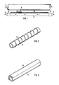
- FIG 1 eine Einrichtung zur Überwachung eines Mediums, bei dem ein Sensorschlauch verwendet wird, für den im Leckagefall ein diffusionsfähiger und detektierbarer Stoff erzeugt wird;
- FIG 2 einen Sensorschlauch mit einem Reaktionsmaterial in Form eines aufgewickelten Metalldrahtes; und
- FIG 3 einen Sensorschlauch mit einem aufgebrachten Reaktionsmaterial in Form einer Folie.
- 1 shows a device for monitoring a medium in which a sensor hose is used, for which a diffusible and detectable substance is generated in the event of a leak;
- 2 shows a sensor tube with a reaction material in the form of a wound metal wire; and
- 3 shows a sensor tube with an applied reaction material in the form of a film.
Nach Figur 1 wird ein zu überwachendes Medium 2, beispielsweise eine Säure, in einer Rohrleitung 4 geführt. Mittels der dargestellten Einrichtung wird hierbei überwacht, ob die Rohrleitung 4 möglicherweise ein Leck 6 aufweist, aus dem das Medium 2 in die Umgebung austritt. Die dargestellte Überwachungseinrichtung umfaßt im wesentlichen einen parallel zur Rohrleitung 4 verlegten Sensorschlauch 8, eine Pumpe 10 an einem Ende dieses Sensorschlauches 8 und einen Detektor oder Sensor 12 für einen nachzuweisenden Stoff am anderen Ende. Mit Hilfe der Pumpe 10 wird ein Transportmedium 14, wie beispielsweise gereinigte Luft, jeweils für eine gewisse Zeit durch den Sensorschlauch 8 gepumpt.According to FIG. 1, a medium 2 to be monitored, for example an acid, is guided in a pipeline 4. The device shown here is used to monitor whether the pipeline 4 may have a leak 6 from which the medium 2 escapes into the environment. The monitoring device shown essentially comprises a
Wichtig ist nun, daß in der Nähe des Sensorschlauches 8 ein Material 16 angeordnet ist, das bei einer Leckage mit dem aus dem Leck 6 austretenden Medium 2 reagiert. Es erzeugt dabei einen Stoff 18, der bezüglich des Sensorschlauches 8 diffusionsfähig ist und der mittels des Detektors 12 detektierbar ist.It is now important that a
Bei dem Stoff 18 kann es sich insbesondere um ein Gas wie Wasserstoff handeln. Und das zu überwachende Medium 2 kann insbesondere eine Säure oder Lauge sein.The
In Figur 1 ist gezeigt, daß das Reaktionsmaterial 16 ein gewendelter Draht sein kann, der parallel zum Sensorschlauch 8 verlegt ist. Bei dem Material 16 kann es sich insbesondere um ein Metall handeln. In Verbindung mit der Erzeugung von Wasserstoff kommt bei der Überwachung einer Säure-Rohrleitung 4 insbesondere Zink in Betracht.In Figure 1 it is shown that the
Aus Figur 1 ist auch ersichtlich, daß sich das Material 16 bevorzugt im Raum zwischen dem Sensorschlauch 8 und der zu überwachenden Rohrleitung 4 befindet.It can also be seen from FIG. 1 that the
Der Sensorschlauch 8 kann in bekannter Weise als LEOS-Schlauch ausgebildet sein. Er kann also beispielsweise ein Drahtgeflecht umfassen. Je nach Anzahl der nachzuweisenden Substanzen oder Stoffe wird man einen oder mehrere Detektoren 12 vorsehen.The
Aus Figur 2 ist eine Ausführung ersichtlich, bei der auf dem Sensorschlauch 8 das Material 16 in Form eines Drahtes aufgewickelt ist. Insbesondere kann der Draht spiral- oder wendelförmig aufgebracht sein. Natürlich können auch voneinander beabstandete Metallringe verwendet werden; der Abstand solcher Ringe beeinflußt jedoch etwas die Ortsauflösung bei der Feststellung der Leckstelle 6. Prinzipiell kann auch ein langgestreckter Draht parallel zur Längsachse des Sensorschlauches 8 verlegt und fixiert sein.FIG. 2 shows an embodiment in which the
In Figur 3 ist eine Ausführungsform gezeigt, bei der das Material 16 auf dem Sensorschlauch 8 in Form einer Folie aufgebracht ist. Diese Folie 16 hat dabei die Gestalt eines Halbzylinders. Es ist ersichtlich, daß zwischen dem Sensorschlauch 8 und der Folie 16 ein geringer Abstand vorgesehen sein kann.FIG. 3 shows an embodiment in which the
Je nach Medium 2 und Material 16 kann der erzeugte Stoff 18 ein besonders gutes Diffusionsverhalten aufweisen, so daß bereits kleine Leckstellen 6 mit ausreichender Signalsicherheit nachgewiesen werden können.Depending on the medium 2 and
Claims (13)
Applications Claiming Priority (2)
| Application Number | Priority Date | Filing Date | Title |
|---|---|---|---|
| DE4125373 | 1991-07-31 | ||
| DE4125373A DE4125373A1 (en) | 1991-07-31 | 1991-07-31 | SENSOR HOSE FOR MONITORING A MEDIUM |
Publications (2)
| Publication Number | Publication Date |
|---|---|
| EP0525593A1 true EP0525593A1 (en) | 1993-02-03 |
| EP0525593B1 EP0525593B1 (en) | 1995-09-20 |
Family
ID=6437420
Family Applications (1)
| Application Number | Title | Priority Date | Filing Date |
|---|---|---|---|
| EP92112462A Expired - Lifetime EP0525593B1 (en) | 1991-07-31 | 1992-07-21 | Sensing hose for monitoring a medium |
Country Status (6)
| Country | Link |
|---|---|
| US (1) | US5271901A (en) |
| EP (1) | EP0525593B1 (en) |
| AT (1) | ATE128228T1 (en) |
| DE (2) | DE4125373A1 (en) |
| DK (1) | DK0525593T3 (en) |
| ES (1) | ES2077942T3 (en) |
Cited By (7)
| Publication number | Priority date | Publication date | Assignee | Title |
|---|---|---|---|---|
| WO1997036159A1 (en) * | 1996-03-26 | 1997-10-02 | Siemens Aktiengesellschaft | Means and method for leakage detection |
| DE10315925A1 (en) * | 2003-04-08 | 2004-10-21 | Ust Umweltsensortechnik Gmbh | Method for identifying and locating leaks in a gas filled system such as cooling systems using a hygroscopic substance which becomes more conductive when moist |
| EP1342998A3 (en) * | 2002-03-08 | 2006-01-18 | UST Umweltsensortechnik GmbH | Procedure and arrangement for detecting leaks in a gas-filled system |
| WO2010089605A1 (en) | 2009-02-06 | 2010-08-12 | Reneuron Limited | Treatment of limb ischemia |
| CN103675946A (en) * | 2013-12-27 | 2014-03-26 | 青岛厚科化学有限公司 | Drop tube type underground installation identification system |
| CN103712068A (en) * | 2013-12-27 | 2014-04-09 | 青岛厚科化学有限公司 | Sleeve-type underground embedded object wireless-transmission automatic early warning system |
| EP3686901A1 (en) | 2009-05-26 | 2020-07-29 | Rapiscan Systems, Inc. | X-ray tomographic inspection method |
Families Citing this family (11)
| Publication number | Priority date | Publication date | Assignee | Title |
|---|---|---|---|---|
| US5573934A (en) * | 1992-04-20 | 1996-11-12 | Board Of Regents, The University Of Texas System | Gels for encapsulation of biological materials |
| US5531357A (en) * | 1994-10-20 | 1996-07-02 | Foamseal, Inc. | Hose containment system |
| DE19536472A1 (en) * | 1995-09-29 | 1997-04-03 | Siemens Ag | Device for determining concentration profiles of liquid or gaseous substances along a route |
| US5731523A (en) * | 1996-03-22 | 1998-03-24 | Aeroquip Corporation | Hose fatigue indicator |
| DE19612947C1 (en) * | 1996-04-01 | 1997-09-11 | Siemens Ag | Leak detection device and method |
| DE10060976B4 (en) * | 2000-12-06 | 2005-06-23 | Framatome Anp Gmbh | Device for leak detection and leak detection |
| DE102010005494A1 (en) * | 2009-11-27 | 2011-06-01 | Inficon Gmbh | Method for testing the density of water-carrying components in a housing |
| CA3007129C (en) * | 2015-12-04 | 2024-02-27 | Instrumar Limited | Apparatus and method of detecting breaches in pipelines |
| US9823184B1 (en) | 2016-05-13 | 2017-11-21 | General Electric Company | Distributed gas detection system and method |
| WO2019213080A1 (en) | 2018-05-01 | 2019-11-07 | Baker Hughes, A Ge Company, Llc | Gas sensor system |
| KR102170028B1 (en) * | 2018-11-27 | 2020-10-26 | 한국원자력연구원 | Sensor tube of humidity sensor and humidity sensor assembly using the same |
Citations (5)
| Publication number | Priority date | Publication date | Assignee | Title |
|---|---|---|---|---|
| GB1148868A (en) * | 1965-05-25 | 1969-04-16 | Cossonay Cableries Trefileries | Fluid hydrocarbon detecting element |
| US3995472A (en) * | 1975-06-26 | 1976-12-07 | Murgor Electric Company, Inc. | Detector system |
| DE2431907C3 (en) * | 1974-07-03 | 1978-03-09 | Wolfgang Dipl.-Phys. Dr.- Ing. 7500 Karlsruhe Issel | Method and device for determining concentration profiles of liquid or gaseous substances along a route |
| DE3321256A1 (en) * | 1983-06-11 | 1984-12-13 | Hochtemperatur-Reaktorbau GmbH, 4600 Dortmund | Leak-detection device for the concrete pressure vessel of a gas-cooled nuclear reactor |
| DE3736177C1 (en) * | 1987-10-26 | 1988-09-01 | Dietzel Karl | Leak monitoring and test equipment reacting to liquids |
Family Cites Families (7)
| Publication number | Priority date | Publication date | Assignee | Title |
|---|---|---|---|---|
| US3959764A (en) * | 1974-10-09 | 1976-05-25 | Dictaphone Corporation | Gas analyzing element |
| JPS5236290A (en) * | 1975-09-18 | 1977-03-19 | Power Reactor & Nuclear Fuel Dev Corp | Liquid sodium leakage detector |
| BE45T1 (en) * | 1978-03-08 | 1980-03-14 | British Gas Corp | CATALYTIC GAS DETECTOR AND ITS MANUFACTURING METHOD |
| US4709577A (en) * | 1983-11-29 | 1987-12-01 | Tracer Research Corporation | System for continuously monitoring for leaks in underground storage tanks |
| JPS6221034A (en) * | 1985-07-19 | 1987-01-29 | Junkosha Co Ltd | Liquid leak detection sensor |
| DE3706869A1 (en) * | 1987-03-04 | 1988-09-15 | Heers & Brockstedt Gmbh | METHOD FOR MONITORING AND, IF REQUIRED, REPAIRING LEAKAGE AT LANDFILLS |
| US5046353A (en) * | 1989-01-26 | 1991-09-10 | Tracer Research Corporation | Underground pipe leak detection system |
-
1991
- 1991-07-31 DE DE4125373A patent/DE4125373A1/en not_active Withdrawn
-
1992
- 1992-07-21 EP EP92112462A patent/EP0525593B1/en not_active Expired - Lifetime
- 1992-07-21 AT AT92112462T patent/ATE128228T1/en not_active IP Right Cessation
- 1992-07-21 ES ES92112462T patent/ES2077942T3/en not_active Expired - Lifetime
- 1992-07-21 DK DK92112462.4T patent/DK0525593T3/en active
- 1992-07-21 DE DE59203734T patent/DE59203734D1/en not_active Expired - Fee Related
- 1992-07-29 US US07/921,840 patent/US5271901A/en not_active Expired - Fee Related
Patent Citations (5)
| Publication number | Priority date | Publication date | Assignee | Title |
|---|---|---|---|---|
| GB1148868A (en) * | 1965-05-25 | 1969-04-16 | Cossonay Cableries Trefileries | Fluid hydrocarbon detecting element |
| DE2431907C3 (en) * | 1974-07-03 | 1978-03-09 | Wolfgang Dipl.-Phys. Dr.- Ing. 7500 Karlsruhe Issel | Method and device for determining concentration profiles of liquid or gaseous substances along a route |
| US3995472A (en) * | 1975-06-26 | 1976-12-07 | Murgor Electric Company, Inc. | Detector system |
| DE3321256A1 (en) * | 1983-06-11 | 1984-12-13 | Hochtemperatur-Reaktorbau GmbH, 4600 Dortmund | Leak-detection device for the concrete pressure vessel of a gas-cooled nuclear reactor |
| DE3736177C1 (en) * | 1987-10-26 | 1988-09-01 | Dietzel Karl | Leak monitoring and test equipment reacting to liquids |
Cited By (10)
| Publication number | Priority date | Publication date | Assignee | Title |
|---|---|---|---|---|
| WO1997036159A1 (en) * | 1996-03-26 | 1997-10-02 | Siemens Aktiengesellschaft | Means and method for leakage detection |
| EP1342998A3 (en) * | 2002-03-08 | 2006-01-18 | UST Umweltsensortechnik GmbH | Procedure and arrangement for detecting leaks in a gas-filled system |
| DE10315925A1 (en) * | 2003-04-08 | 2004-10-21 | Ust Umweltsensortechnik Gmbh | Method for identifying and locating leaks in a gas filled system such as cooling systems using a hygroscopic substance which becomes more conductive when moist |
| DE10315925B4 (en) * | 2003-04-08 | 2012-01-05 | Ust Umweltsensortechnik Gmbh | Method and arrangement for detecting leaks in a gas-filled system |
| WO2010089605A1 (en) | 2009-02-06 | 2010-08-12 | Reneuron Limited | Treatment of limb ischemia |
| EP3686901A1 (en) | 2009-05-26 | 2020-07-29 | Rapiscan Systems, Inc. | X-ray tomographic inspection method |
| CN103675946A (en) * | 2013-12-27 | 2014-03-26 | 青岛厚科化学有限公司 | Drop tube type underground installation identification system |
| CN103712068A (en) * | 2013-12-27 | 2014-04-09 | 青岛厚科化学有限公司 | Sleeve-type underground embedded object wireless-transmission automatic early warning system |
| CN103712068B (en) * | 2013-12-27 | 2017-01-04 | 青岛厚科化学有限公司 | A kind of bushing type underground installation is wirelessly transferred automatic early-warning system |
| CN103675946B (en) * | 2013-12-27 | 2017-01-04 | 青岛厚科化学有限公司 | One fall tubular type underground installation mark system |
Also Published As
| Publication number | Publication date |
|---|---|
| DE59203734D1 (en) | 1995-10-26 |
| ES2077942T3 (en) | 1995-12-01 |
| DE4125373A1 (en) | 1993-02-04 |
| EP0525593B1 (en) | 1995-09-20 |
| ATE128228T1 (en) | 1995-10-15 |
| US5271901A (en) | 1993-12-21 |
| DK0525593T3 (en) | 1996-02-12 |
Similar Documents
| Publication | Publication Date | Title |
|---|---|---|
| EP0525593B1 (en) | Sensing hose for monitoring a medium | |
| DE2431907B2 (en) | METHOD AND DEVICE FOR DETERMINING CONCENTRATION PROFILES OF LIQUID OR GAS MATERIALS ALONG A LINE | |
| EP1784602B1 (en) | Collector line for leakage monitoring and leakage location | |
| EP0890088B1 (en) | Means and method for leakage detection | |
| EP0891538A1 (en) | Leak detection device and process | |
| EP0637271B1 (en) | Monitoring device for a rubbish dump and process for locating leaks | |
| EP0633460B1 (en) | Long-term leak monitoring device for double-walled containers, in particular double-walled container bottoms | |
| DE4125739A1 (en) | Specimen extractor with several measurement points, e.g. for air in chemical plant - has extraction line with pumped transport medium, controlled inlet valves at each ,measurement point, and specific material sensor | |
| DE4015190A1 (en) | FLAT FLOOR TANK AND METHOD FOR LEAK MONITORING OF FLAT FLOOR TANKS | |
| DE2917255A1 (en) | CRACK INDICATOR FOR MONITORING THE INSULATION OF LIQUID GAS TANKS | |
| EP0542042B1 (en) | Procedure and device for monitoring the space between two sealing elements | |
| EP0525594B1 (en) | Method and apparatus for monitoring a medium by means of a sensing hose | |
| EP0575441B1 (en) | Element for sealing and monitoring a body, in particular a refuse dump | |
| DE202018101539U1 (en) | Device for locating a leak at a fluid-carrying section | |
| EP0870145A1 (en) | Concrete, stoneware or cast pipe | |
| DE19925842A1 (en) | Sensor for detecting oxygen in refuse landfill sites, waste water lagoons and rivers, consists of enclosed hollow vessel which has wall made of a plastic which is permeable to specific gas | |
| DE3417332A1 (en) | Device for detecting leaks, in particular in pipelines and containers | |
| EP0676043A1 (en) | Sensor pipes | |
| DE4123728A1 (en) | Gas- and water-proofing and monitoring system esp. for refuse deposits - pumps transport medium, e.g. dried air, through sealed body and has sensor responsive to at least one monitored material | |
| DE4134380A1 (en) | Gas and liquid leak monitoring appts., esp. in doubly sealed refuse deposit - has sensor tube in monitoring chamber carrying pumped transport inert gas and connected to sensor of monitored medium | |
| DE3904577C2 (en) | Fault locating device on jacketed pipes | |
| DE19643637A1 (en) | Unit for detecting and locating leaks of e.g. salt solution from pipeline | |
| DE4131085A1 (en) | Waste deposit site monitoring appts. - has sensor tube carrying transport medium through control space, and sensor connected to tube to detect monitored material | |
| EP0082172A1 (en) | Method and device for continuously monitoring an installation containing a fluid | |
| EP0542041B1 (en) | Procedure and device for monitoring the space between two sealing elements |
Legal Events
| Date | Code | Title | Description |
|---|---|---|---|
| PUAI | Public reference made under article 153(3) epc to a published international application that has entered the european phase |
Free format text: ORIGINAL CODE: 0009012 |
|
| AK | Designated contracting states |
Kind code of ref document: A1 Designated state(s): AT BE CH DE DK ES FR GB IT LI NL |
|
| 17P | Request for examination filed |
Effective date: 19930308 |
|
| 17Q | First examination report despatched |
Effective date: 19940519 |
|
| GRAA | (expected) grant |
Free format text: ORIGINAL CODE: 0009210 |
|
| AK | Designated contracting states |
Kind code of ref document: B1 Designated state(s): AT BE CH DE DK ES FR GB IT LI NL |
|
| REF | Corresponds to: |
Ref document number: 128228 Country of ref document: AT Date of ref document: 19951015 Kind code of ref document: T |
|
| REF | Corresponds to: |
Ref document number: 59203734 Country of ref document: DE Date of ref document: 19951026 |
|
| REG | Reference to a national code |
Ref country code: ES Ref legal event code: FG2A Ref document number: 2077942 Country of ref document: ES Kind code of ref document: T3 |
|
| ITF | It: translation for a ep patent filed |
Owner name: STUDIO JAUMANN |
|
| ET | Fr: translation filed | ||
| GBT | Gb: translation of ep patent filed (gb section 77(6)(a)/1977) |
Effective date: 19951113 |
|
| REG | Reference to a national code |
Ref country code: DK Ref legal event code: T3 |
|
| PLBE | No opposition filed within time limit |
Free format text: ORIGINAL CODE: 0009261 |
|
| STAA | Information on the status of an ep patent application or granted ep patent |
Free format text: STATUS: NO OPPOSITION FILED WITHIN TIME LIMIT |
|
| 26N | No opposition filed | ||
| PGFP | Annual fee paid to national office [announced via postgrant information from national office to epo] |
Ref country code: GB Payment date: 19970620 Year of fee payment: 6 Ref country code: AT Payment date: 19970620 Year of fee payment: 6 |
|
| PGFP | Annual fee paid to national office [announced via postgrant information from national office to epo] |
Ref country code: ES Payment date: 19970710 Year of fee payment: 6 Ref country code: BE Payment date: 19970710 Year of fee payment: 6 |
|
| PGFP | Annual fee paid to national office [announced via postgrant information from national office to epo] |
Ref country code: NL Payment date: 19970714 Year of fee payment: 6 |
|
| PGFP | Annual fee paid to national office [announced via postgrant information from national office to epo] |
Ref country code: DK Payment date: 19970715 Year of fee payment: 6 |
|
| PGFP | Annual fee paid to national office [announced via postgrant information from national office to epo] |
Ref country code: FR Payment date: 19970718 Year of fee payment: 6 |
|
| PGFP | Annual fee paid to national office [announced via postgrant information from national office to epo] |
Ref country code: DE Payment date: 19970918 Year of fee payment: 6 |
|
| PGFP | Annual fee paid to national office [announced via postgrant information from national office to epo] |
Ref country code: CH Payment date: 19971028 Year of fee payment: 6 |
|
| PG25 | Lapsed in a contracting state [announced via postgrant information from national office to epo] |
Ref country code: GB Free format text: LAPSE BECAUSE OF NON-PAYMENT OF DUE FEES Effective date: 19980721 Ref country code: AT Free format text: LAPSE BECAUSE OF NON-PAYMENT OF DUE FEES Effective date: 19980721 |
|
| PG25 | Lapsed in a contracting state [announced via postgrant information from national office to epo] |
Ref country code: ES Free format text: LAPSE BECAUSE OF THE APPLICANT RENOUNCES Effective date: 19980722 |
|
| PG25 | Lapsed in a contracting state [announced via postgrant information from national office to epo] |
Ref country code: LI Free format text: LAPSE BECAUSE OF NON-PAYMENT OF DUE FEES Effective date: 19980731 Ref country code: DK Free format text: LAPSE BECAUSE OF NON-PAYMENT OF DUE FEES Effective date: 19980731 Ref country code: CH Free format text: LAPSE BECAUSE OF NON-PAYMENT OF DUE FEES Effective date: 19980731 Ref country code: BE Free format text: LAPSE BECAUSE OF NON-PAYMENT OF DUE FEES Effective date: 19980731 |
|
| BERE | Be: lapsed |
Owner name: SIEMENS A.G. Effective date: 19980731 |
|
| PG25 | Lapsed in a contracting state [announced via postgrant information from national office to epo] |
Ref country code: NL Free format text: LAPSE BECAUSE OF NON-PAYMENT OF DUE FEES Effective date: 19990201 |
|
| GBPC | Gb: european patent ceased through non-payment of renewal fee |
Effective date: 19980721 |
|
| REG | Reference to a national code |
Ref country code: CH Ref legal event code: PL |
|
| PG25 | Lapsed in a contracting state [announced via postgrant information from national office to epo] |
Ref country code: FR Free format text: LAPSE BECAUSE OF NON-PAYMENT OF DUE FEES Effective date: 19990331 |
|
| NLV4 | Nl: lapsed or anulled due to non-payment of the annual fee |
Effective date: 19990201 |
|
| PG25 | Lapsed in a contracting state [announced via postgrant information from national office to epo] |
Ref country code: DE Free format text: LAPSE BECAUSE OF NON-PAYMENT OF DUE FEES Effective date: 19990501 |
|
| REG | Reference to a national code |
Ref country code: FR Ref legal event code: ST |
|
| REG | Reference to a national code |
Ref country code: DK Ref legal event code: EBP |
|
| REG | Reference to a national code |
Ref country code: ES Ref legal event code: FD2A Effective date: 20001009 |
|
| PG25 | Lapsed in a contracting state [announced via postgrant information from national office to epo] |
Ref country code: IT Free format text: LAPSE BECAUSE OF NON-PAYMENT OF DUE FEES;WARNING: LAPSES OF ITALIAN PATENTS WITH EFFECTIVE DATE BEFORE 2007 MAY HAVE OCCURRED AT ANY TIME BEFORE 2007. THE CORRECT EFFECTIVE DATE MAY BE DIFFERENT FROM THE ONE RECORDED. Effective date: 20050721 |