EP0525988A2 - Ink jet recording apparatus - Google Patents
Ink jet recording apparatus Download PDFInfo
- Publication number
- EP0525988A2 EP0525988A2 EP92306013A EP92306013A EP0525988A2 EP 0525988 A2 EP0525988 A2 EP 0525988A2 EP 92306013 A EP92306013 A EP 92306013A EP 92306013 A EP92306013 A EP 92306013A EP 0525988 A2 EP0525988 A2 EP 0525988A2
- Authority
- EP
- European Patent Office
- Prior art keywords
- recovery operation
- ink
- recovery
- recording head
- discharging
- Prior art date
- Legal status (The legal status is an assumption and is not a legal conclusion. Google has not performed a legal analysis and makes no representation as to the accuracy of the status listed.)
- Withdrawn
Links
Images


Classifications
-
- B—PERFORMING OPERATIONS; TRANSPORTING
- B41—PRINTING; LINING MACHINES; TYPEWRITERS; STAMPS
- B41J—TYPEWRITERS; SELECTIVE PRINTING MECHANISMS, i.e. MECHANISMS PRINTING OTHERWISE THAN FROM A FORME; CORRECTION OF TYPOGRAPHICAL ERRORS
- B41J2/00—Typewriters or selective printing mechanisms characterised by the printing or marking process for which they are designed
- B41J2/005—Typewriters or selective printing mechanisms characterised by the printing or marking process for which they are designed characterised by bringing liquid or particles selectively into contact with a printing material
- B41J2/01—Ink jet
- B41J2/135—Nozzles
- B41J2/165—Preventing or detecting of nozzle clogging, e.g. cleaning, capping or moistening for nozzles
- B41J2/16517—Cleaning of print head nozzles
- B41J2/1652—Cleaning of print head nozzles by driving a fluid through the nozzles to the outside thereof, e.g. by applying pressure to the inside or vacuum at the outside of the print head
- B41J2/16523—Waste ink collection from caps or spittoons, e.g. by suction
Definitions
- the present invention relates to an ink jet recording apparatus, and more particularly, to an improved recording apparatus which recovers a recording head for discharging ink from defective discharging of ink, suitable for use in a copy machine, a facsimile, a computer, a word processor, or an apparatus composed of any of these machines.
- An ink jet recording apparatus performs recording by driving, on the basis of output data signals, driving elements corresponding to a plurality of ink droplet discharging nozzles formed in a recording head to form droplets of ink supplied to the recording head and sputter same from discharging orifices onto a recording medium.
- This type of ink jet recording apparatus is susceptible to suffer from defective discharging of ink from the nozzles due to attachment of dust and agglutinative ink on a discharging orifice face during a normal operation; bubble collected in the ink head during a normal operation; ink stuck near the discharging orifices when the ink jet recording apparatus is unpacked; and so on.
- methods for recovering normal ink discharging to maintain a good image quality to suck ink from the discharging orifices; wipe a discharging orifice arranged face of the recording head by means of a wiper blade; wipe the discharging orifice arranged face with a porous member; and discharge ink not for printing.
- Japanese Laid-open Patent Application No. 63-224956 discloses a method of recovering an ink discharging operation for attending to a case where a more powerful recovery operation is required than usual such as the unpacking, by increasing a duration or frequency of a recovery operation when a recovery operation instruction is input from the operator within a predetermined time after a power supply is turned on.
- This prior art fixes a recovery operation amount in conformity with the most frequently occurring defective discharging state in order to recover a recording head from defective discharging with a single recovery operation as well as to reduce an ink consumption to the utmost to eliminate uselessly discharged ink.
- a normal operation of the ink jet recording apparatus implies a variety of causes of the defective discharging, e.g., accumulation of dust and stain on a discharge orifice face; rooted contamination due to the repetition of attachment and drying of agglutinative ink; and increase of bubble collected in a recording head, as described above, a single recovery operation may often be insufficient to recover the recording head from a printing disabled condition.
- a recovery operation amount may be previously set to be large enough to recover possible defective discharging which may occur in several years.
- Such a large recovery operation amount, if set, is not favorable because waste of ink results therefrom, and the recording head is largely damaged by the recovery operation.
- the present invention has been made in view of the above-mentioned problems from a new viewpoint which has not been estimated.
- An object of the present invention is to provide an ink jet recording apparatus for solving the technical problem mentioned in the foregoing "Related Background Art” which is capable of ensuring a recovery of a recording head from defective discharging if occurs during an image output operation, by at least two recovery operations.
- Another object of the present invention is to provide an ink jet recording apparatus which is characterized by recovering means for executing a recovery operation for recovering a recording head for discharging ink from a defective ink discharging state; instructing means for instructing the recovering means to execute the recovery operation; and recovery operation control means, responsive to an instruction to execute the next recovery operation which is generated after the recovery operation has been executed by said recovering means, for controlling said recovering means to execute the next recovery operation which provides a larger recovery amount than that of said first recovery operation on the basis of a state of said recording head from a time at which the first recovery operation was completed to a time at which the instruction is issued to said recovering means to execute the next recovery operation.
- the recovery operation control means determines that the first recovery operation performed by the recovering means is not sufficient on the basis of a state of the recording head from a time the first recovery operation was completed to a time at which the instruction is issued to the recovering means to execute the next recovery operation.
- a recovery operation providing a larger recovery amount than that of the first recovery operation is performed by conditioning differently from the first recovery operation with respect to all or a combination of some of an ink sucking amount; an ink sucking time; an ink sucking pressure; the frequency of wiping with a wiper blade; the frequency of wiping a discharging orifice face of the recording head; an urging force for wiping; and the frequency of preparatory discharging; and so on, or by adding another recovery operation to the first recovery operation.
- at least two recovery operations ensures the recovery of the recording head from the defective discharging state.
- a recovery unit 1 is provided with a variety of cleaning means for recovery operations.
- the recovery unit 1 comprises a cap closely contacted on an ink discharging orifice face 7 of a recording head 6 for sucking ink from an ink discharging orifices of the recording head 6 through an ink sucking port 11 connected to a suction pump not shown; a porous member 3 abutted to the ink discharging orifice face 7 to remove stains therefrom; and a wiper blade 4 abutted on the ink discharging orifice face 7 to remove foreign substances such as dust.
- the recording head 6 is driven by a carriage motor 10 through a carriage belt 9 to move on a carriage shaft 8 in the direction indicated by the arrow while sputtering ink droplets on a recording sheet 5 or a recording medium to perform recording.
- a recording head employed in an ink jet recording apparatus comprises liquid discharging orifices, a liquid path, an energy acting portion provided in part of this liquid path, and an energy generating means for generating droplet forming energy to act on a liquid existing in the energy acting portion.
- the energy generating means for generating such energy may be one that employs an electromechanical transducer such as a piezoelectric element; one that irradiates a liquid with electromagnetic wave such as laser such that the liquid absorbs the electromagnetic wave to be heated, as the result of which the liquid is discharged and sputtered in the form of droplets by the action of the heating; one that heats a liquid by means of an electro-thermal transducer to discharge the liquid; and so on.
- an electromechanical transducer such as a piezoelectric element
- electromagnetic wave such as laser
- the recording head employed in the ink jet recording apparatus adapted to discharge a liquid by means of thermal energy can perform recording in a high resolution since it can be provided with liquid discharging orifices aligned in a high density for discharging a recording liquid to form droplets to be sputtered.
- the recording head employing an electro-thermal transducer as an energy generating means is advantageous in many aspects; a readily made reduction of the entire size of the recording head; utilization of advantages of the IC technologies and micromachining technologies which recently exhibit a great progress and an improved reliability in the field of semiconductor; and easy formation of the recording head in a large size or in a plane shape (two-dimensional shape).
- This kind of recording head for ink jet recording therefore, can be readily formed in a multi-nozzle type or mounted in a high density with a good adaptability to madd production and at a low production cost.
- the ink jet recording head employing an electro-thermal transducer for an energy generating means and produced via semiconductor producing processes is generally provided with liquid paths corresponding to respective ink discharge orifices, and an electro-thermal transducer as a means for acting thermal energy on a liquid filled in each of the liquid paths to discharge the liquid from corresponding ink discharging orifices to form droplets to be sputtered, where the respective liquid paths are supplied with ink from a common liquid chamber communicating with the respective liquid paths.
- the assignee of the present invention has filed a method of forming liquid paths by the steps of successively stacking a solid layer for forming at least liquid path on a first substrate, an activation energy ray hardening material layer and a second substrate; stacking a mask on the second substrate; irradiating an active energy ray from above the mask to harden at least walls of liquid paths in the active energy ray hardening material layer as constituents; removing the solid layer and unhardened portions of the active energy ray hardening material layer from between the two substrates; and forming at least liquid paths (see Japanese Patent Laid-open Application No. 62-253457).
- Fig. 3 is a perspective view schematically showing the structure of the above-mentioned ink jet recording head.
- a recording head 101 is produced by semiconductor producing processes including etching deposition, sputtering and so on, and comprised of an electro-thermal transducer 103, an electrode 104, a hardened active energy ray hardening material layer 210 having liquid paths 110, all laminated on a first substrate 102, and a top plate 106.
- a recording liquid 112 is supplied from a liquid storage, not shown, through a liquid supplying tube 107 to a common liquid chamber 108.
- Reference numeral 109 designates a connector for the liquid supplying tube.
- the recording liquid 112 supplied in the common liquid chamber 108 is supplied to the liquid paths 110 by capillary action and maintained stable by meniscus formed in ink discharging orifices at the tip of the liquid paths.
- the electro-thermal transducer 103 is conducted to heat the liquid on the surface of the electro-thermal transducer and give rise to a bubbling phenomenon in the liquid, whereby droplets are discharged from the ink discharging orifices 11 by the bubbling energy.
- the above-mentioned structure constitutes a multiple-nozzle ink jet recording head formed by high density liquid path piping capable of a high discharging orifice density of 400 dpi.
- Fig. 4 is a block diagram showing an example of a control system of the recording apparatus constructed as described above.
- a control unit 1010 comprises a recovery operation control means for controlling a recovery means, on the basis of a state of the recording head from a time at which the first recovery operation was completed to a time at which the next recovery operation is instructed, to have the recovery means to perform a recovery operation providing a larger recovery amount than that of the first recovery operation.
- control unit is composed of an MPU 1000 for controlling respective units; a ROM 1001 for storing programs corresponding to a control procedure executed by the MPU 1000; a RAM used as a work area during the execution of the control procedure; and a timer 1004 for counting a time which has elapsed from the first recovery operation to the generation of the instruction to execute the next recovery operation.
- the control unit 1010 is connected with an instruction switch 21 and a printer unit 23 through an interface unit 1003.
- a control signal outputted from the control unit 1010 is used to drive a recovery unit 1, a recording head 6 through a head driver 25, and a carriage motor 10 through a motor driver 27.
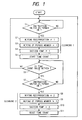
- Fig. 1 shows a flow chart of a sequence of recovery processes according to the first embodiment.
- the control unit 1010 determines whether or not the operator pressed the instruction switch 21 when defective printing occurs (step S1). If the control unit 1010 determines that the instruction switch was pressed, that is, if the answer to the step S1 is YES, cleaning 1, which is a first recovery operation, is executed as will be later described (steps S2 - S4).
- the recording head 6 is driven on the carriage shaft 8 by the movement of the carriage belt 9 driven by the carriage motor 10 to start moving toward the direction of a wiper blade position P3.
- the wiper blade 4 is advanced from a standby position by a driving means (not shown) arranged in the recovery unit 1 to move in the direction of abutting to the recording head 6 and stops at a position advanced by a predetermined overlap portion from the discharging orifice surface 7 of the recording head 6.
- the wiper blade 4 contacts the discharging orifice face 7 of the recording head 6 to wipe same and then stops at a position P2. Then, the recording head 6 moves in the direction P4.
- the discharging orifice face 7 of the recording head 6 is reciprocally wiped by the wiper blade 4 so that dust and foreign substances on the discharging orifice face 7 are removed (step S2).
- the recording head 6 stops at the position P4, while the wiper blade 4 is returned to the original standby position by a driving force developed by the above- mentioned driving means, not shown, arranged in the recovery unit 1.
- the porous member 3 is next advanced by a driving force developed by the driving means, not shown, arranged in the recovery unit 1 from a standby position to the direction of abutting to the recording head 6, and stops at a position at which the porous member 3 can contact the discharging orifice face 7 of the recording head 6.
- the recording head 6 remaining at the position P4 begins to move toward the position P2 at which the discharging orifice face 7 is brought into contact with the porous member 3, and stains on the discharging orifice face 7 is wiped by the porous member while the recording head 6 moves up to the position P1 (step S3).
- the porous member 3 is returned to the standby position by a driving force developed by the driving means, not shown, arranged in the recovery unit 1.
- the cap 2 is advanced by a driving force developed by the driving means in the direction of abutting to the recording head 6, contacts the discharging orifice face, and stops with a predetermined urging force being maintained. Then, a suction pressure generated by a suction pump, not shown, is propagated to a suction port arranged in the cap 2, whereby a pressure in the cap 2 is decreased, with the result that ink is sucked from the discharging orifices of the recording head 6 and the plurality of discharging orifices are ensured to be in a normal meniscus state (step S4).
- step S5 The operation of the cleaning 1 is completed by the above-mentioned sequence of processes.
- the timer 1004 is started to count a time (step S5).
- the operator of the recording apparatus performs test printing to confirm whether the recording head was recovered by the cleaning 1. It should be noted that even if seemingly good results are obtained with respect to the recovery of the recording head, a trouble may occur again after a certain number of sheets are printed in the case where the recording head is not completely recovered. If a trouble is again detected by the confirmation, the instruction switch 21 is again pressed (step S7).
- the timer counts a time elapsed after the cleaning 1 was completed, and the control means 1010 determines whether or not the elapsed time exceeds a set time T (step S6).
- the control means 1010 determines whether or not the instruction switch 21 has been pressed (step S7). If it is determined that the instruction switch 21 has been pressed (YES at step S7), determination is made that defective discharging again occurred by the same cause due to a lack of recovery provided by the cleaning 1. The program then proceeds to cleaning 2 in order to perform a radical recovery.
- the procedure of the cleaning 2, similar to that of the cleaning 1, includes a wiping process for wiping the discharging orifice face 7 of the recording head 6 with the wiper blade (step S8); a wiping process for wiping the discharging orifice face 7 of the recording head 6 with a porous member (step S9); and a suction process for sucking ink from the discharging orifices of the recording head 6 by means of a suction pump (step S10).
- the wiper blade contacted with the discharging orifice face 7 is reciprocated only once, and the wiping of the discharging orifice face 7 with the porous member is performed once.
- the reciprocal movement of the wiper blade is performed twice, and the wiping by the use of the porous member three times.
- the cleaning 1 performs once the suction of ink by the suction pump, while the cleaning 2 performs same three times.
- a more powerful recovery sequence is provided in the cleaning 2 by increasing the frequency of the respective recovering processes as compared with the cleaning 1.
- step S11 the timer 1004 is reset to zero (step S11). If the instruction switch 21 is not turned on until the elapsed time exceeds the set time T (NO at step S6), it is determined that the cleaning 1 was sufficient to recover the recording head, and the program is returned immediately before step S1.
- the set time T may be set to a time required for the recording apparatus to print one page of a standard text, for example, 30 seconds. This value was introduced from the experimental results showing that a majority of repeated defective printing caused by insufficient recovery in the first cleaning occurs in the same page as the first defective printing.
- the present embodiment has been explained such that the cleaning 2 differs from the cleaning 1 in the frequencies of the respective recovering processes.
- the conditions different between the cleanings 1 and 2 may be:
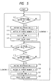
- Fig. 5 shows a flow chart of a sequence of recovery processes according to a second embodiment of the present invention.
- the second embodiment differs from the first embodiment in that when the number of discharging pulse supplied to an electro-thermal transducer of a recording head from the completion of a recovery operation provided by a cleaning 1 to a depression of an instruction switch 21 for executing a cleaning 2, is not more than a predetermined set value P, it is determined that the recovery operation provided by the cleaning 1 is not sufficient, and the powerful cleaning 2 is executed.
- a control unit 1010 starts counting discharging pulses upon completion of the cleaning 1 (step S16), and the counted number of discharging pulses is stored in a RAM backed up by a battery arranged in the recording apparatus.
- steps S17 and S18 if the instruction switch 21 is turned on before the counted number of the pulses exceeds the set value P, it is determined that the recovery of the recording head provided by the cleaning 1 is not sufficient, and the cleaning 2 is executed for completely recovering the recording head from defective discharging (steps S19 - S21).
- step S22 the pulse count value is reset to zero.
- the number of pulses set in this embodiment is determined, for example, from a number of pulses required to discharge an amount of ink existing in a space extending from a filter arranged in an ink tank through an ink supplying path to ink discharging orifices arranged in the recording head. This is because a majority of incomplete recovery of the recording head is caused by bubble accumulated in the recording head. When such bubble exists in the space extending from the filter to the ink discharging orifices, the bubble moves together with a flow of ink and reaches the ink discharging orifices, whereby the bubble adversely affects the recording as a cause of instable ink discharging.
- an insufficient recovery of the recording head is determined by the number of discharging pulses.
- the determination of the insufficient recovery may be made by utilizing the fact that the number of discharging pulses is approximately proportional to the number of printed characters. Specifically, if the number of printed characters from the completion of the recovery operation by the cleaning 1 to a depression of the instruction switch 21 for executing the cleaning 2 is within a predetermined value, for example, the number of characters for consuming an amount of ink existing in the space extending from the filter arranged in the ink tank through the ink supplying path to the ink discharging orifices arranged in the recording head, it is determined that the recovery operation provided by the cleaning 1 is insufficient and the powerful cleaning 2 is to be executed.
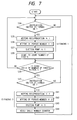
- Fig. 6 shows a flow chart of a sequence of recovery processes according to a third embodiment of the present invention.
- the third embodiment differs from the first embodiment in that determination is made that a recovery operation provided by a cleaning 1 is insufficient to recover a recording head from defective discharging and a powerful cleaning 2 is to be executed, if an amount of ink consumed from the completion of the cleaning 1 to a depression of an instruction switch 21 for executing the cleaning 2 is not more than a predetermined set amount I.
- a control unit 1010 starts measuring an amount of ink consumption (step S27). If the instruction switch 21 is turned on before the ink consumption amount exceeds the set amount I, it is determined that a recovery provided by the cleaning 1 is insufficient, and the cleaning 2 is executed to completely recover the recording head from defective discharging (steps S30 - S32).
- step S33 the measured value of the ink consumption amount is reset to zero.
- the rest of processes are the same as those of the first embodiment, so that explanation thereof will be omitted.
- the set ink amount I is set to an ink capacity of a space extending from a filter arranged in an ink tank through an ink supplying path to ink discharging orifices arranged in the recording head. This is because a majority of incomplete recovery of the recording head is caused by bubble accumulated in the recording head. When such bubble exists in the space extending from the filter to the ink discharging orifices, the bubble moves together with a flow of ink and reaches the ink discharging orifices, whereby the bubble adversely affects the recording as a cause of instable ink discharging.
- a consumed ink amount may be measured by an ink remaining amount detector arranged in the recording apparatus, the ink supplying path or the ink tank.
- an ink remaining amount detector may be implemented by a known device which detects a decreasing amount of ink caused by the consumption of the ink by means of a mechanical or optical means to calculate a consumed amount.
- Fig. 7 is a flow chart showing a sequence of recovery processes according to a fourth embodiment of the present invention.
- the fourth embodiment differs from the first embodiment in that determination is made that a recovery operation provided by cleaning 1 is insufficient and powerful cleaning 2 is to be executed, if the number of sheets of recording medium on which printing is performed from the completion of the cleaning 1 to a depression of an instruction switch 21 for executing a cleaning 2 is within a predetermined number of sheets S.
- a control unit 1010 starts counting a number of sheets of recorded medium (step S38).
- steps S39 and S40 if the instruction switch 21 is turned on before the number of printed recording sheets exceeds the set value S, it is determined that a recovery provided by the cleaning 1 is not sufficient so that the cleaning 2 is executed to completely recover the recording head from defective discharging (steps S41 - S43).
- step S45 the counted number of sheets is reset to zero.
- the rest of the processes are the same as those of the first embodiment, so that explanation thereof will be omitted.
- the set number S of recording sheets is set, for example, to one. This value is determined from experimental results showing that a majority of repeated defective printing caused by an insufficient recovery provided by the first cleaning occurs in the same page.
- the number of printed sheets may be counted, for example, by a sheet absence detecting sensor which detects the top edge and bottom edge of a sheet being fed.
- the recovering means when a second recovery operation is instructed from the instructing means after a first recovery operation has been performed by the recovering means, the recovering means is instructed to perform the second recovery operation providing a large recovery amount than that of the first recovery operation, on the basis of a state of the recording head from a time at which the first recovery operation was completed to a time at which the instruction is given to execute the next recovery operation.
- state of the recording head from a time at which the first recovery operation was completed to a time at which the instruction is given to execute the next recovery operation is not limited to that shown in the foregoing embodiments but can be set to another condition without departing from the spirit of the present invention.
- the present invention produces excellent effects particularly in a recording apparatus employing a recording head of a type which utilizes thermal energy to form droplets which are adhered to the surface of a recording medium to perform recording.
- the typical structure and principle of this type of recording apparatus preferably employs the basic principles disclosed, for example, in U.S. Patent Nos. 4,723,129 and 4,740,796.
- This system is applicable to either of so-called on-demand type and continuous type.
- this system is effective in the on-demand type since the on-demand type is adapted to apply at least one driving signal for causing a rapid temperature rise corresponding to recording information and exceeding the nuclear boiling to an electric-thermal converter arranged corresponding to a sheet and a liquid pathway in which liquid (ink) is held so as to generate thermal energy in the electric-thermal transducer, cause film boiling to occur on a heat acting face of a recording heat, and consequently form bubbles in the liquid (ink) which correspond to the driving signal one by one.
- the liquid (ink) is discharged from a discharging orifice by the growth and contraction of bubble to form at least one droplet.
- a pulse signal is used as the driving signal because the growth and contraction of bubble are immediately and properly controlled thereby so that an ink discharging mechanism, particularly excellent in a response characteristic, is achieved.
- this pulse-shaped driving signal those described in the specifications of U.S. Patent Nos. 4,463,359 and 4,345,262 are suitable. Further, if conditions described in the specification of U.S. Patent No. 4,313,124 concerning a temperature rising ratio on the heat acting face are employed, further excellent recording can be achieved.
- the structure of the recording head may be such one that employs inventions described in the specifications of U.S. Patents Nos. 4,558,333 and 4,459,600 which disclose a structure in which a heat acting portion is arranged in a bent region, in addition to a combined structure (a straight flow pathway or a perpendicular flow pathway) formed of a discharging orifice, a liquid pathway and an electro-thermal transducer as disclosed in the above-mentioned respective specifications.
- the recording head may be constructed on the basis of Japanese Laid-open Patent Application No. 59-123670 which discloses a structure where common slits serve as discharging portions for a plurality of electro-thermal transducers and Japanese Laid-open Patent Application No. 59-138461 which discloses a structure where an opening for absorbing pressure wave of thermal energy is arranged corresponding to a discharging portion.
- a recording head of a full line type having a length corresponding to the width of the widest recording medium on which a recording apparatus can record may be constituted by either of an assembly of a plurality of recording heads to extend over the length or a single integrated recording head.
- the recording apparatus of the present invention may be such one that has not only a recording mode in a main color such as black but also at least one of a plural color mode using different colors or a full color mode by mixing different colors, by the use of either an integral recording head or a combination of plural recording heads.
- the ink may be such one that is solidified at temperatures less than room temperatures and softened or liquified at room temperatures.
- the ink jet method generally controls the temperature of ink in a range between 30 ° C and 70°C to maintain the viscosity of the ink in a stably dischargeable state, the ink may be in a liquid state when a recording signal is supplied.
- the present invention is also applicable to the case where thermal energy is positively utilized as energy for changing ink from a solid state to a liquid state to prevent the temperature from rising or the ink from being evaporated due to the thermal energy. It is therefore possible to utilize ink which is normally solid and liquified by applying heat thereto. After all, the present invention is applicable to a recording head utilizing ink which is liquified only by applying thermal energy thereto, e.g., ink which is liquified and discharged by applying thereto thermal energy in response to a recording signal; ink which has already begun to become solid when reaching a recording medium; and so on.
- ink may be held as a liquid or solid substance in recesses or through-holes of a porous sheet and arranged opposite to an electric-thermal converter, as described in Japanese Laid-open Patent Application No. 54-56847 or 60-71260.
- the most effective way for the above-mentioned respective ink is to carry out the foregoing film boiling method.
- an ink jet recording apparatus to which the present invention is applied may be, other than that used as an image outputting terminal for an information processing apparatus such as a computer, in the form of a copier combined with a reader or the like, a facsimile apparatus having transmitting and receiving functions, and so on.
- Fig. 8 is a block diagram schematically showing the structure of a recording apparatus according to the present invention which is applied to an information processing apparatus having a function of a word processor, a personal computer, a facsimile apparatus and a copier.
- a control unit 201 for controlling the whole device comprises a CPU such as a microprocessor and a variety of I/O ports to supply and receive control signals and data signals to and from respective sections.
- a display 202 displays on its screen a variety of menus, text information, image data read by an image reader 207, and so on.
- a transparent and pressure-sensitive touch panel 203 is mounted over the screen of the display 202 to allow the operator to select an item and input a coordinate position by pressing the surface thereof with a finger.
- An FM (Frequency Modulation) sound source 204 reads and FM-modulates music information created by a music editor or the like and stored a memory 213 or an external memory device 212. An electric signal from the FM sound source 204 is converted to an audible sound by a speaker 205.
- a printer 206 is implemented by a recording apparatus according to the present invention as an output terminal for a word processor, a personal computer, a facsimile apparatus and a copier.
- An image reader 207 for opto-electrically reading original data and inputting a signal corresponding thereto is arranged at a midway location of an original transporting pathway for reading a variety of originals such as those to be transmitted via facsimile or to be copied.
- a facsimile transmitter/receiver 208 is provided with an interface function for transmitting original data read by the image reader 207 via facsimile to the outside and receiving and decoding a facsimile signal transmitted thereto from the outside.
- a telephone 209 has a variety of telephone functions such as a normal telephone function and an absent receiving function.
- the memory 213 comprises a ROM for storing a system program, a manager program, application programs, character fonts, a dictionary and so on; a RAM for storing an application program and character information loaded from the external memory device 212; and a video RAM.
- a keyboard 211 is provided to allow the operator to input text information and a variety of commands therethrough.
- the external memory device 212 employs a floppy disk or a hard disk as a storing medium for storing character information, music and audio information, user's application program, and so on.
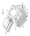
- Fig. 9 shows the outer appearance of the information processing apparatus of Fig. 8.
- a flat panel display 301 is constituted by a liquid crystal or the like and displays a variety of means, graphical information and text information.
- the display 301 is equipped with a touch panel mounted thereover for inputting a coordinate or selecting an item in a menu by pressing the surface thereof with a finger.
- a hand set 302 is provided for the case where the apparatus functions as a telephone.
- a keyboard 303 is mountably and removably connected to a body via a cord for inputting a variety of text information and data.
- the keyboard 202 is also provided with a variety of function keys 304.
- a slot 305 is for inserting a floppy disk.
- a sheet carrier 306 carries originals to be read by the image reader 207. Read originals are discharged from the rear of the apparatus. Data received via facsimile is recorded by an ink jet printer 307.
- the display 301 may be constituted by a cathode ray tube, a flat panel type one such as a liquid crystal display utilizing a ferroelectric liquid crystal is desirable because of a compact, thin and light-weight display realized thereby.
- the information processing apparatus shown in Fig. 9 functions as a personal computer or a word processor, a variety of information inputted from the keyboard 211 is processed by the control unit 201 in accordance with a predetermined program and outputted by the printer 206 as an image.
- facsimile information inputted through a communication cable from the facsimile transmitter/receiver 208 is processed for reception by the control unit 201 in accordance with a predetermined program and outputted as a received image by the printer 206.
- the apparatus When the apparatus functions as a copier, an original is read by the image reader 207, and the read original data is outputted through the control unit 201 by the printer 206 as a copy image.
- original data read by the image reader 207 is processed for transmission by the control unit 201 in accordance with a predetermined program, and transmitted through the facsimile transmitter/receiver 208 to a communication cable.
- the abovementioned information processing apparatus may be of an integral type which has an ink jet printer built in a body as shown in Fig. 10. Such an integral type apparatus can further enhance the portability.
- portions having the same functions as those in Fig. 9 are designated the corresponding reference numerals.
Abstract
Description
- The present invention relates to an ink jet recording apparatus, and more particularly, to an improved recording apparatus which recovers a recording head for discharging ink from defective discharging of ink, suitable for use in a copy machine, a facsimile, a computer, a word processor, or an apparatus composed of any of these machines.
- An ink jet recording apparatus performs recording by driving, on the basis of output data signals, driving elements corresponding to a plurality of ink droplet discharging nozzles formed in a recording head to form droplets of ink supplied to the recording head and sputter same from discharging orifices onto a recording medium.
- This type of ink jet recording apparatus is susceptible to suffer from defective discharging of ink from the nozzles due to attachment of dust and agglutinative ink on a discharging orifice face during a normal operation; bubble collected in the ink head during a normal operation; ink stuck near the discharging orifices when the ink jet recording apparatus is unpacked; and so on. To solve this problem, there have been proposed, as methods for recovering normal ink discharging to maintain a good image quality, to suck ink from the discharging orifices; wipe a discharging orifice arranged face of the recording head by means of a wiper blade; wipe the discharging orifice arranged face with a porous member; and discharge ink not for printing.
- Japanese Laid-open Patent Application No. 63-224956 discloses a method of recovering an ink discharging operation for attending to a case where a more powerful recovery operation is required than usual such as the unpacking, by increasing a duration or frequency of a recovery operation when a recovery operation instruction is input from the operator within a predetermined time after a power supply is turned on.
- This prior art fixes a recovery operation amount in conformity with the most frequently occurring defective discharging state in order to recover a recording head from defective discharging with a single recovery operation as well as to reduce an ink consumption to the utmost to eliminate uselessly discharged ink. However, since a normal operation of the ink jet recording apparatus implies a variety of causes of the defective discharging, e.g., accumulation of dust and stain on a discharge orifice face; rooted contamination due to the repetition of attachment and drying of agglutinative ink; and increase of bubble collected in a recording head, as described above, a single recovery operation may often be insufficient to recover the recording head from a printing disabled condition.
- On the other hand, in view of recovery of a recording head which gradually becomes difficult to achieve, a recovery operation amount may be previously set to be large enough to recover possible defective discharging which may occur in several years. Such a large recovery operation amount, if set, is not favorable because waste of ink results therefrom, and the recording head is largely damaged by the recovery operation.
- In the recovering method described in the foregoing Japanese Laid-open Patent Application No. 63-224956, only when a recovery is instructed after a predetermined time from power-on of an ink jet recording apparatus, recovery operation duration and frequency are increased such that a more powerful recovery operation is performed only upon unpacking the ink jet recording apparatus, exchanging the head, and initially filling ink. Thus, if a long time has elapsed after the printing device was turned on, the powerful recovery is not performed. Also, when defective discharging gradually becomes worse while the ink jet recording apparatus is used, the powerful recovery is not performed either. Whereas, if a trouble occurs accidentally within the predetermined time after the power-on, an excessively powerful recovery operation is performed, which may lead to waste of ink and increase of damage on the recording head.
- In many cases, defective discharging which cannot be solved by a single recovery operation is not improved even if the same recovery operation is repeated afterward. For this reason, when defective discharging is not solved even after the normal recovery operation has been repeated, the operator is forced to instruct a powerful recovery operation in accordance with an instruction manual, whereby the operator suffers from a bad usability and a lot of wasteful time required to recover the recording head from the defective discharging.
- The present invention has been made in view of the above-mentioned problems from a new viewpoint which has not been estimated.
- An object of the present invention is to provide an ink jet recording apparatus for solving the technical problem mentioned in the foregoing "Related Background Art" which is capable of ensuring a recovery of a recording head from defective discharging if occurs during an image output operation, by at least two recovery operations.
- Another object of the present invention is to provide an ink jet recording apparatus which is characterized by recovering means for executing a recovery operation for recovering a recording head for discharging ink from a defective ink discharging state; instructing means for instructing the recovering means to execute the recovery operation; and recovery operation control means, responsive to an instruction to execute the next recovery operation which is generated after the recovery operation has been executed by said recovering means, for controlling said recovering means to execute the next recovery operation which provides a larger recovery amount than that of said first recovery operation on the basis of a state of said recording head from a time at which the first recovery operation was completed to a time at which the instruction is issued to said recovering means to execute the next recovery operation.
- According to the ink jet recording apparatus provided by the present invention, when the operator inputs through the instructing means an instruction to execute the next recovery operation after a first recovery operation was performed by the recovering means for defective ink discharging of the ink head, the recovery operation control means determines that the first recovery operation performed by the recovering means is not sufficient on the basis of a state of the recording head from a time the first recovery operation was completed to a time at which the instruction is issued to the recovering means to execute the next recovery operation.
- Therefore, if a time elapsed from a time at which the first recovery operation was completed to a time at which the instruction is issued to the recovering means to execute the next recovery operation is within the predetermined value, a recovery operation providing a larger recovery amount than that of the first recovery operation is performed by conditioning differently from the first recovery operation with respect to all or a combination of some of an ink sucking amount; an ink sucking time; an ink sucking pressure; the frequency of wiping with a wiper blade; the frequency of wiping a discharging orifice face of the recording head; an urging force for wiping; and the frequency of preparatory discharging; and so on, or by adding another recovery operation to the first recovery operation. Thus, even if the recording head suffers from defective discharging while outputting an image, at least two recovery operations ensures the recovery of the recording head from the defective discharging state.
-
- Fig. 1 is a flow chart showing a sequence of recovery processes according to a first embodiment of the present invention;
- Fig. 2 is a perspective view showing an example of a recording unit constituting an ink jet recording apparatus of the present invention;
- Fig. 3 is a perspective view schematically showing the structure of an ink jet recording head;
- Fig. 4 is a block diagram showing an example of the configuration of a control system constituting the ink jet recording apparatus of the present invention;
- Fig. 5 is a flow chart showing a sequence of recovery processes according to a second embodiment;
- Fig. 6 is a flow chart showing a sequence of recovery processes according to a third embodiment;
- Fig. 7 is a flow chart showing a sequence of recovery processes according to a fourth embodiment;
- Fig. 8 is a block diagram schematically showing an information processing apparatus to which the ink jet recording apparatus of the present invention is applied;
- Fig. 9 is a diagram illustrating the appearance of an example of the information processing apparatus shown in Fig. 8; and
- Fig. 10 is a diagram showing the appearance of another example of the information processing apparatus shown in Fig. 8.
- Embodiments of the present invention will hereinafter be described in detail with reference to the accompanying drawings.
- Referring first to Fig. 2, there is illustrated an example of a recording unit of an ink jet recording apparatus according to the present invention. In Fig. 2, a
recovery unit 1 is provided with a variety of cleaning means for recovery operations. Specifically, therecovery unit 1 comprises a cap closely contacted on an inkdischarging orifice face 7 of a recording head 6 for sucking ink from an ink discharging orifices of the recording head 6 through anink sucking port 11 connected to a suction pump not shown; aporous member 3 abutted to the ink dischargingorifice face 7 to remove stains therefrom; and awiper blade 4 abutted on the inkdischarging orifice face 7 to remove foreign substances such as dust. The recording head 6 is driven by acarriage motor 10 through acarriage belt 9 to move on acarriage shaft 8 in the direction indicated by the arrow while sputtering ink droplets on arecording sheet 5 or a recording medium to perform recording. - Next, description will be made to the discharging principle of a recording head which is employed in the ink jet recording apparatus of the embodiment as a recording means of the present invention. Generally, a recording head employed in an ink jet recording apparatus comprises liquid discharging orifices, a liquid path, an energy acting portion provided in part of this liquid path, and an energy generating means for generating droplet forming energy to act on a liquid existing in the energy acting portion.
- The energy generating means for generating such energy may be one that employs an electromechanical transducer such as a piezoelectric element; one that irradiates a liquid with electromagnetic wave such as laser such that the liquid absorbs the electromagnetic wave to be heated, as the result of which the liquid is discharged and sputtered in the form of droplets by the action of the heating; one that heats a liquid by means of an electro-thermal transducer to discharge the liquid; and so on. Among these means, the recording head employed in the ink jet recording apparatus adapted to discharge a liquid by means of thermal energy can perform recording in a high resolution since it can be provided with liquid discharging orifices aligned in a high density for discharging a recording liquid to form droplets to be sputtered.
- The recording head employing an electro-thermal transducer as an energy generating means is advantageous in many aspects; a readily made reduction of the entire size of the recording head; utilization of advantages of the IC technologies and micromachining technologies which recently exhibit a great progress and an improved reliability in the field of semiconductor; and easy formation of the recording head in a large size or in a plane shape (two-dimensional shape). This kind of recording head for ink jet recording, therefore, can be readily formed in a multi-nozzle type or mounted in a high density with a good adaptability to madd production and at a low production cost.
- The ink jet recording head employing an electro-thermal transducer for an energy generating means and produced via semiconductor producing processes is generally provided with liquid paths corresponding to respective ink discharge orifices, and an electro-thermal transducer as a means for acting thermal energy on a liquid filled in each of the liquid paths to discharge the liquid from corresponding ink discharging orifices to form droplets to be sputtered, where the respective liquid paths are supplied with ink from a common liquid chamber communicating with the respective liquid paths.
- As to a method of producing an ink discharging orifice section, the assignee of the present invention has filed a method of forming liquid paths by the steps of successively stacking a solid layer for forming at least liquid path on a first substrate, an activation energy ray hardening material layer and a second substrate; stacking a mask on the second substrate; irradiating an active energy ray from above the mask to harden at least walls of liquid paths in the active energy ray hardening material layer as constituents; removing the solid layer and unhardened portions of the active energy ray hardening material layer from between the two substrates; and forming at least liquid paths (see Japanese Patent Laid-open Application No. 62-253457).
- Fig. 3 is a perspective view schematically showing the structure of the above-mentioned ink jet recording head. As is apparent from this drawing, a
recording head 101 is produced by semiconductor producing processes including etching deposition, sputtering and so on, and comprised of an electro-thermal transducer 103, anelectrode 104, a hardened active energy ray hardeningmaterial layer 210 havingliquid paths 110, all laminated on afirst substrate 102, and atop plate 106. - In the
recording head 101 thus constructed, arecording liquid 112 is supplied from a liquid storage, not shown, through a liquid supplyingtube 107 to a commonliquid chamber 108.Reference numeral 109 designates a connector for the liquid supplying tube. Therecording liquid 112 supplied in the commonliquid chamber 108 is supplied to theliquid paths 110 by capillary action and maintained stable by meniscus formed in ink discharging orifices at the tip of the liquid paths. Then, the electro-thermal transducer 103 is conducted to heat the liquid on the surface of the electro-thermal transducer and give rise to a bubbling phenomenon in the liquid, whereby droplets are discharged from theink discharging orifices 11 by the bubbling energy. The above-mentioned structure constitutes a multiple-nozzle ink jet recording head formed by high density liquid path piping capable of a high discharging orifice density of 400 dpi. - Fig. 4 is a block diagram showing an example of a control system of the recording apparatus constructed as described above. In Fig. 4, a
control unit 1010 comprises a recovery operation control means for controlling a recovery means, on the basis of a state of the recording head from a time at which the first recovery operation was completed to a time at which the next recovery operation is instructed, to have the recovery means to perform a recovery operation providing a larger recovery amount than that of the first recovery operation. More specifically, the control unit is composed of anMPU 1000 for controlling respective units; aROM 1001 for storing programs corresponding to a control procedure executed by theMPU 1000; a RAM used as a work area during the execution of the control procedure; and atimer 1004 for counting a time which has elapsed from the first recovery operation to the generation of the instruction to execute the next recovery operation. - The
control unit 1010 is connected with aninstruction switch 21 and aprinter unit 23 through aninterface unit 1003. A control signal outputted from thecontrol unit 1010 is used to drive arecovery unit 1, a recording head 6 through ahead driver 25, and acarriage motor 10 through amotor driver 27. - Fig. 1 shows a flow chart of a sequence of recovery processes according to the first embodiment. The
control unit 1010 determines whether or not the operator pressed theinstruction switch 21 when defective printing occurs (step S1). If thecontrol unit 1010 determines that the instruction switch was pressed, that is, if the answer to the step S1 is YES, cleaning 1, which is a first recovery operation, is executed as will be later described (steps S2 - S4). - Referring also to Fig. 2, the recording head 6 is driven on the
carriage shaft 8 by the movement of thecarriage belt 9 driven by thecarriage motor 10 to start moving toward the direction of a wiper blade position P3. Simultaneously, thewiper blade 4 is advanced from a standby position by a driving means (not shown) arranged in therecovery unit 1 to move in the direction of abutting to the recording head 6 and stops at a position advanced by a predetermined overlap portion from the dischargingorifice surface 7 of the recording head 6. - By the movement of the recording head 6 in the direction of the blade position P3, the
wiper blade 4 contacts the dischargingorifice face 7 of the recording head 6 to wipe same and then stops at a position P2. Then, the recording head 6 moves in the direction P4. By this sequence of processes, the dischargingorifice face 7 of the recording head 6 is reciprocally wiped by thewiper blade 4 so that dust and foreign substances on the dischargingorifice face 7 are removed (step S2). The recording head 6 then stops at the position P4, while thewiper blade 4 is returned to the original standby position by a driving force developed by the above- mentioned driving means, not shown, arranged in therecovery unit 1. - The
porous member 3 is next advanced by a driving force developed by the driving means, not shown, arranged in therecovery unit 1 from a standby position to the direction of abutting to the recording head 6, and stops at a position at which theporous member 3 can contact the dischargingorifice face 7 of the recording head 6. Here, the recording head 6 remaining at the position P4 begins to move toward the position P2 at which the dischargingorifice face 7 is brought into contact with theporous member 3, and stains on the dischargingorifice face 7 is wiped by the porous member while the recording head 6 moves up to the position P1 (step S3). Then, theporous member 3 is returned to the standby position by a driving force developed by the driving means, not shown, arranged in therecovery unit 1. - Next, the
cap 2 is advanced by a driving force developed by the driving means in the direction of abutting to the recording head 6, contacts the discharging orifice face, and stops with a predetermined urging force being maintained. Then, a suction pressure generated by a suction pump, not shown, is propagated to a suction port arranged in thecap 2, whereby a pressure in thecap 2 is decreased, with the result that ink is sucked from the discharging orifices of the recording head 6 and the plurality of discharging orifices are ensured to be in a normal meniscus state (step S4). - The operation of the
cleaning 1 is completed by the above-mentioned sequence of processes. Next, thetimer 1004 is started to count a time (step S5). In this event, the operator of the recording apparatus performs test printing to confirm whether the recording head was recovered by thecleaning 1. It should be noted that even if seemingly good results are obtained with respect to the recovery of the recording head, a trouble may occur again after a certain number of sheets are printed in the case where the recording head is not completely recovered. If a trouble is again detected by the confirmation, theinstruction switch 21 is again pressed (step S7). The timer counts a time elapsed after thecleaning 1 was completed, and the control means 1010 determines whether or not the elapsed time exceeds a set time T (step S6). If the elapsed time does not exceed the set time T (YES at step S6), the control means 1010 determines whether or not theinstruction switch 21 has been pressed (step S7). If it is determined that theinstruction switch 21 has been pressed (YES at step S7), determination is made that defective discharging again occurred by the same cause due to a lack of recovery provided by thecleaning 1. The program then proceeds to cleaning 2 in order to perform a radical recovery. - The procedure of the
cleaning 2, similar to that of thecleaning 1, includes a wiping process for wiping the dischargingorifice face 7 of the recording head 6 with the wiper blade (step S8); a wiping process for wiping the dischargingorifice face 7 of the recording head 6 with a porous member (step S9); and a suction process for sucking ink from the discharging orifices of the recording head 6 by means of a suction pump (step S10). In thecleaning 1, the wiper blade contacted with the dischargingorifice face 7 is reciprocated only once, and the wiping of the dischargingorifice face 7 with the porous member is performed once. Whereas, in thecleaning 2, the reciprocal movement of the wiper blade is performed twice, and the wiping by the use of the porous member three times. - The
cleaning 1 performs once the suction of ink by the suction pump, while thecleaning 2 performs same three times. Thus, a more powerful recovery sequence is provided in thecleaning 2 by increasing the frequency of the respective recovering processes as compared with thecleaning 1. - Referring again to the flow chart of Fig. 1, the
timer 1004 is reset to zero (step S11). If theinstruction switch 21 is not turned on until the elapsed time exceeds the set time T (NO at step S6), it is determined that thecleaning 1 was sufficient to recover the recording head, and the program is returned immediately before step S1. - The set time T may be set to a time required for the recording apparatus to print one page of a standard text, for example, 30 seconds. This value was introduced from the experimental results showing that a majority of repeated defective printing caused by insufficient recovery in the first cleaning occurs in the same page as the first defective printing.
- Incidentally, the present embodiment has been explained such that the
cleaning 2 differs from the cleaning 1 in the frequencies of the respective recovering processes. Alternatively, the conditions different between thecleanings - (1) the reciprocal movement of the wiper blade contacted with the discharging orifice face is made faster, and an abutted length of the wiper blade with the discharging orifice face is extended;
- (2) the urging force applied to the porous member against the discharging orifice face is increased; and
- (3) the suction pressure generated by the suction pump is enhanced, whereby the respective processes of the
cleaning 2 are made different from those of thecleaning 1, which results in obtaining a more powerful recovery force for the recording head. - As described above, by changing operation conditions of cleaning in response to the
instruction switch 21 turned on within a predetermined time from a first recovery operation to perform a powerful recovery operation at a second time, it is possible to compensate for a lack of recovery provided by the first recovery operation to completely recover the recording head from a defective discharging state. - Fig. 5 shows a flow chart of a sequence of recovery processes according to a second embodiment of the present invention. Briefly, the second embodiment differs from the first embodiment in that when the number of discharging pulse supplied to an electro-thermal transducer of a recording head from the completion of a recovery operation provided by a
cleaning 1 to a depression of aninstruction switch 21 for executing acleaning 2, is not more than a predetermined set value P, it is determined that the recovery operation provided by thecleaning 1 is not sufficient, and thepowerful cleaning 2 is executed. - Specifically, a
control unit 1010 starts counting discharging pulses upon completion of the cleaning 1 (step S16), and the counted number of discharging pulses is stored in a RAM backed up by a battery arranged in the recording apparatus. Next, at steps S17 and S18, if theinstruction switch 21 is turned on before the counted number of the pulses exceeds the set value P, it is determined that the recovery of the recording head provided by thecleaning 1 is not sufficient, and thecleaning 2 is executed for completely recovering the recording head from defective discharging (steps S19 - S21). - Next, the pulse count value is reset to zero (step S22). The rest of the processes are the same as those of the first embodiment, so that explanation thereof will be omitted.
- The number of pulses set in this embodiment is determined, for example, from a number of pulses required to discharge an amount of ink existing in a space extending from a filter arranged in an ink tank through an ink supplying path to ink discharging orifices arranged in the recording head. This is because a majority of incomplete recovery of the recording head is caused by bubble accumulated in the recording head. When such bubble exists in the space extending from the filter to the ink discharging orifices, the bubble moves together with a flow of ink and reaches the ink discharging orifices, whereby the bubble adversely affects the recording as a cause of instable ink discharging.
- In the above described second embodiment, an insufficient recovery of the recording head is determined by the number of discharging pulses. Alternatively, the determination of the insufficient recovery may be made by utilizing the fact that the number of discharging pulses is approximately proportional to the number of printed characters. Specifically, if the number of printed characters from the completion of the recovery operation by the cleaning 1 to a depression of the
instruction switch 21 for executing thecleaning 2 is within a predetermined value, for example, the number of characters for consuming an amount of ink existing in the space extending from the filter arranged in the ink tank through the ink supplying path to the ink discharging orifices arranged in the recording head, it is determined that the recovery operation provided by thecleaning 1 is insufficient and thepowerful cleaning 2 is to be executed. - Fig. 6 shows a flow chart of a sequence of recovery processes according to a third embodiment of the present invention. The third embodiment differs from the first embodiment in that determination is made that a recovery operation provided by a
cleaning 1 is insufficient to recover a recording head from defective discharging and apowerful cleaning 2 is to be executed, if an amount of ink consumed from the completion of thecleaning 1 to a depression of aninstruction switch 21 for executing thecleaning 2 is not more than a predetermined set amount I. - First, after the completion of the
cleaning 1, acontrol unit 1010 starts measuring an amount of ink consumption (step S27). If theinstruction switch 21 is turned on before the ink consumption amount exceeds the set amount I, it is determined that a recovery provided by thecleaning 1 is insufficient, and thecleaning 2 is executed to completely recover the recording head from defective discharging (steps S30 - S32). - Next, the measured value of the ink consumption amount is reset to zero (step S33). The rest of processes are the same as those of the first embodiment, so that explanation thereof will be omitted.
- The set ink amount I is set to an ink capacity of a space extending from a filter arranged in an ink tank through an ink supplying path to ink discharging orifices arranged in the recording head. This is because a majority of incomplete recovery of the recording head is caused by bubble accumulated in the recording head. When such bubble exists in the space extending from the filter to the ink discharging orifices, the bubble moves together with a flow of ink and reaches the ink discharging orifices, whereby the bubble adversely affects the recording as a cause of instable ink discharging.
- Incidentally, a consumed ink amount may be measured by an ink remaining amount detector arranged in the recording apparatus, the ink supplying path or the ink tank. Such an ink remaining amount detector may be implemented by a known device which detects a decreasing amount of ink caused by the consumption of the ink by means of a mechanical or optical means to calculate a consumed amount.
- Fig. 7 is a flow chart showing a sequence of recovery processes according to a fourth embodiment of the present invention. The fourth embodiment differs from the first embodiment in that determination is made that a recovery operation provided by cleaning 1 is insufficient and
powerful cleaning 2 is to be executed, if the number of sheets of recording medium on which printing is performed from the completion of thecleaning 1 to a depression of aninstruction switch 21 for executing acleaning 2 is within a predetermined number of sheets S. - First, after the completion of the
cleaning 1, acontrol unit 1010 starts counting a number of sheets of recorded medium (step S38). At steps S39 and S40, if theinstruction switch 21 is turned on before the number of printed recording sheets exceeds the set value S, it is determined that a recovery provided by thecleaning 1 is not sufficient so that thecleaning 2 is executed to completely recover the recording head from defective discharging (steps S41 - S43). - Next, the counted number of sheets is reset to zero (step S45). The rest of the processes are the same as those of the first embodiment, so that explanation thereof will be omitted.
- The set number S of recording sheets is set, for example, to one. This value is determined from experimental results showing that a majority of repeated defective printing caused by an insufficient recovery provided by the first cleaning occurs in the same page.
- The number of printed sheets may be counted, for example, by a sheet absence detecting sensor which detects the top edge and bottom edge of a sheet being fed.
- According to the present invention as described above in detail, when a second recovery operation is instructed from the instructing means after a first recovery operation has been performed by the recovering means, the recovering means is instructed to perform the second recovery operation providing a large recovery amount than that of the first recovery operation, on the basis of a state of the recording head from a time at which the first recovery operation was completed to a time at which the instruction is given to execute the next recovery operation. It should be noted that the above-mentioned "state of the recording head from a time at which the first recovery operation was completed to a time at which the instruction is given to execute the next recovery operation" is not limited to that shown in the foregoing embodiments but can be set to another condition without departing from the spirit of the present invention.
- Among a variety of ink jet recording methods, the present invention produces excellent effects particularly in a recording apparatus employing a recording head of a type which utilizes thermal energy to form droplets which are adhered to the surface of a recording medium to perform recording.
- The typical structure and principle of this type of recording apparatus preferably employs the basic principles disclosed, for example, in U.S. Patent Nos. 4,723,129 and 4,740,796. This system is applicable to either of so-called on-demand type and continuous type. Particularly, this system is effective in the on-demand type since the on-demand type is adapted to apply at least one driving signal for causing a rapid temperature rise corresponding to recording information and exceeding the nuclear boiling to an electric-thermal converter arranged corresponding to a sheet and a liquid pathway in which liquid (ink) is held so as to generate thermal energy in the electric-thermal transducer, cause film boiling to occur on a heat acting face of a recording heat, and consequently form bubbles in the liquid (ink) which correspond to the driving signal one by one. The liquid (ink) is discharged from a discharging orifice by the growth and contraction of bubble to form at least one droplet. It is preferable that a pulse signal is used as the driving signal because the growth and contraction of bubble are immediately and properly controlled thereby so that an ink discharging mechanism, particularly excellent in a response characteristic, is achieved. As this pulse-shaped driving signal, those described in the specifications of U.S. Patent Nos. 4,463,359 and 4,345,262 are suitable. Further, if conditions described in the specification of U.S. Patent No. 4,313,124 concerning a temperature rising ratio on the heat acting face are employed, further excellent recording can be achieved.
- The structure of the recording head may be such one that employs inventions described in the specifications of U.S. Patents Nos. 4,558,333 and 4,459,600 which disclose a structure in which a heat acting portion is arranged in a bent region, in addition to a combined structure (a straight flow pathway or a perpendicular flow pathway) formed of a discharging orifice, a liquid pathway and an electro-thermal transducer as disclosed in the above-mentioned respective specifications.
- Additionally, the recording head may be constructed on the basis of Japanese Laid-open Patent Application No. 59-123670 which discloses a structure where common slits serve as discharging portions for a plurality of electro-thermal transducers and Japanese Laid-open Patent Application No. 59-138461 which discloses a structure where an opening for absorbing pressure wave of thermal energy is arranged corresponding to a discharging portion.
- A recording head of a full line type having a length corresponding to the width of the widest recording medium on which a recording apparatus can record may be constituted by either of an assembly of a plurality of recording heads to extend over the length or a single integrated recording head.
- Further additionally, the recording apparatus of the present invention may be such one that has not only a recording mode in a main color such as black but also at least one of a plural color mode using different colors or a full color mode by mixing different colors, by the use of either an integral recording head or a combination of plural recording heads.
- In the foregoing embodiments of the present invention, although ink was explained as a liquid, the ink may be such one that is solidified at temperatures less than room temperatures and softened or liquified at room temperatures. Alternatively, since the ink jet method generally controls the temperature of ink in a range between 30 ° C and 70°C to maintain the viscosity of the ink in a stably dischargeable state, the ink may be in a liquid state when a recording signal is supplied.
- The present invention is also applicable to the case where thermal energy is positively utilized as energy for changing ink from a solid state to a liquid state to prevent the temperature from rising or the ink from being evaporated due to the thermal energy. It is therefore possible to utilize ink which is normally solid and liquified by applying heat thereto. After all, the present invention is applicable to a recording head utilizing ink which is liquified only by applying thermal energy thereto, e.g., ink which is liquified and discharged by applying thereto thermal energy in response to a recording signal; ink which has already begun to become solid when reaching a recording medium; and so on. In these cases, ink may be held as a liquid or solid substance in recesses or through-holes of a porous sheet and arranged opposite to an electric-thermal converter, as described in Japanese Laid-open Patent Application No. 54-56847 or 60-71260. In the present invention, the most effective way for the above-mentioned respective ink is to carry out the foregoing film boiling method.
- Further additionally, an ink jet recording apparatus to which the present invention is applied may be, other than that used as an image outputting terminal for an information processing apparatus such as a computer, in the form of a copier combined with a reader or the like, a facsimile apparatus having transmitting and receiving functions, and so on.
- Fig. 8 is a block diagram schematically showing the structure of a recording apparatus according to the present invention which is applied to an information processing apparatus having a function of a word processor, a personal computer, a facsimile apparatus and a copier. In Fig. 8, a
control unit 201 for controlling the whole device comprises a CPU such as a microprocessor and a variety of I/O ports to supply and receive control signals and data signals to and from respective sections. Adisplay 202 displays on its screen a variety of menus, text information, image data read by animage reader 207, and so on. A transparent and pressure-sensitive touch panel 203 is mounted over the screen of thedisplay 202 to allow the operator to select an item and input a coordinate position by pressing the surface thereof with a finger. - An FM (Frequency Modulation)
sound source 204 reads and FM-modulates music information created by a music editor or the like and stored a memory 213 or anexternal memory device 212. An electric signal from theFM sound source 204 is converted to an audible sound by aspeaker 205. Aprinter 206 is implemented by a recording apparatus according to the present invention as an output terminal for a word processor, a personal computer, a facsimile apparatus and a copier. - An
image reader 207 for opto-electrically reading original data and inputting a signal corresponding thereto is arranged at a midway location of an original transporting pathway for reading a variety of originals such as those to be transmitted via facsimile or to be copied. A facsimile transmitter/receiver 208 is provided with an interface function for transmitting original data read by theimage reader 207 via facsimile to the outside and receiving and decoding a facsimile signal transmitted thereto from the outside. Atelephone 209 has a variety of telephone functions such as a normal telephone function and an absent receiving function. The memory 213 comprises a ROM for storing a system program, a manager program, application programs, character fonts, a dictionary and so on; a RAM for storing an application program and character information loaded from theexternal memory device 212; and a video RAM. - A
keyboard 211 is provided to allow the operator to input text information and a variety of commands therethrough. Theexternal memory device 212 employs a floppy disk or a hard disk as a storing medium for storing character information, music and audio information, user's application program, and so on. - Fig. 9 shows the outer appearance of the information processing apparatus of Fig. 8. In Fig. 9, a
flat panel display 301 is constituted by a liquid crystal or the like and displays a variety of means, graphical information and text information. Thedisplay 301 is equipped with a touch panel mounted thereover for inputting a coordinate or selecting an item in a menu by pressing the surface thereof with a finger. A hand set 302 is provided for the case where the apparatus functions as a telephone. - A
keyboard 303 is mountably and removably connected to a body via a cord for inputting a variety of text information and data. Thekeyboard 202 is also provided with a variety offunction keys 304. Aslot 305 is for inserting a floppy disk. - A
sheet carrier 306 carries originals to be read by theimage reader 207. Read originals are discharged from the rear of the apparatus. Data received via facsimile is recorded by anink jet printer 307. - Incidentally, although the
display 301 may be constituted by a cathode ray tube, a flat panel type one such as a liquid crystal display utilizing a ferroelectric liquid crystal is desirable because of a compact, thin and light-weight display realized thereby. When the information processing apparatus shown in Fig. 9 functions as a personal computer or a word processor, a variety of information inputted from thekeyboard 211 is processed by thecontrol unit 201 in accordance with a predetermined program and outputted by theprinter 206 as an image. When the apparatus functions as a facsimile transmitter, facsimile information inputted through a communication cable from the facsimile transmitter/receiver 208 is processed for reception by thecontrol unit 201 in accordance with a predetermined program and outputted as a received image by theprinter 206. - When the apparatus functions as a copier, an original is read by the
image reader 207, and the read original data is outputted through thecontrol unit 201 by theprinter 206 as a copy image. When the apparatus functions as a facsimile transmitter, original data read by theimage reader 207 is processed for transmission by thecontrol unit 201 in accordance with a predetermined program, and transmitted through the facsimile transmitter/receiver 208 to a communication cable. Incidentally, the abovementioned information processing apparatus may be of an integral type which has an ink jet printer built in a body as shown in Fig. 10. Such an integral type apparatus can further enhance the portability. In Fig. 10, portions having the same functions as those in Fig. 9 are designated the corresponding reference numerals. - Since a high-grade recording image can be created by applying the recording apparatus of the present invention to the above explained multifunction type information processing apparatus, the functions of the information processing apparatus can be further improved.
- According to the ink jet recording apparatus of the present invention as described above in detail, when defective discharging of a recording head occurs while outputting an image, at least two recovery operations can ensure the recovery of the recording head from the defective discharging state, thereby rendering it unnecessary to repeatedly perform the recovery operation many times as before.
Claims (10)
Applications Claiming Priority (2)
| Application Number | Priority Date | Filing Date | Title |
|---|---|---|---|
| JP17679191A JPH0516391A (en) | 1991-07-17 | 1991-07-17 | Ink jet recording device |
| JP176791/91 | 1991-07-17 |
Publications (2)
| Publication Number | Publication Date |
|---|---|
| EP0525988A2 true EP0525988A2 (en) | 1993-02-03 |
| EP0525988A3 EP0525988A3 (en) | 1993-02-24 |
Family
ID=16019914
Family Applications (1)
| Application Number | Title | Priority Date | Filing Date |
|---|---|---|---|
| EP19920306013 Withdrawn EP0525988A3 (en) | 1991-07-17 | 1992-06-30 | Ink jet recording apparatus |
Country Status (2)
| Country | Link |
|---|---|
| EP (1) | EP0525988A3 (en) |
| JP (1) | JPH0516391A (en) |
Cited By (10)
| Publication number | Priority date | Publication date | Assignee | Title |
|---|---|---|---|---|
| EP0630753A2 (en) * | 1993-06-24 | 1994-12-28 | Hewlett-Packard Company | Wiper for ink jet printhead nozzle member |
| EP0865924A2 (en) * | 1997-03-18 | 1998-09-23 | Brother Kogyo Kabushiki Kaisha | Ink jet Printer |
| US6024432A (en) * | 1996-10-21 | 2000-02-15 | Seiko Epson Corporation | Ink-jet recording apparatus |
| US6290322B1 (en) * | 1993-09-10 | 2001-09-18 | Canon Kabushiki Kaisha | Image recording method and apparatus |
| US6722755B2 (en) * | 2001-01-31 | 2004-04-20 | Canon Kabushiki Kaisha | Ink-jet recording apparatus |
| EP1462260A3 (en) * | 2003-03-27 | 2005-12-14 | Brother Kogyo Kabushiki Kaisha | Image formation apparatus and recovery ejection method of print head |
| US7232204B2 (en) * | 2004-02-02 | 2007-06-19 | Seiko Epson Corporation | Printing apparatus, recording head cleaning method, control process and computerized cleaning program for the recording head in a printer |
| US7775626B2 (en) | 2005-08-15 | 2010-08-17 | Seiko Epson Corporation | Cleaning device, inkjet printer, and an inkjet printer cleaning method |
| US8147050B2 (en) | 2008-07-31 | 2012-04-03 | Brother Kogyo Kabushiki Kaisha | Liquid droplet jetting apparatus |
| US8256863B2 (en) | 2009-03-27 | 2012-09-04 | Brother Kogyo Kabushiki Kaisha | Ink-jet printer |
Families Citing this family (9)
| Publication number | Priority date | Publication date | Assignee | Title |
|---|---|---|---|---|
| US6206497B1 (en) | 1993-09-10 | 2001-03-27 | Canon Kabushiki Kaisha | Liquid ejecting apparatus with variable wiping of a liquid ejection head |
| JP3539487B2 (en) * | 1999-11-11 | 2004-07-07 | セイコーエプソン株式会社 | Ink jet recording device |
| JP4627878B2 (en) * | 2000-01-19 | 2011-02-09 | セイコーインスツル株式会社 | Inkjet head maintenance mechanism |
| JP4746146B2 (en) * | 2000-01-19 | 2011-08-10 | セイコーインスツル株式会社 | Inkjet head maintenance mechanism |
| US6786566B2 (en) * | 2001-12-17 | 2004-09-07 | Brother Kogyo Kabushiki Kaisha | Ink jet recording apparatus |
| JP2005144737A (en) * | 2003-11-12 | 2005-06-09 | Konica Minolta Holdings Inc | Inkjet printer and method for cleaning recording head |
| JP4742510B2 (en) * | 2004-03-31 | 2011-08-10 | ブラザー工業株式会社 | Inkjet printer recovery device, recovery method thereof, and recovery program thereof |
| CN105856847A (en) * | 2016-04-07 | 2016-08-17 | 郑州新世纪数码打印科技有限公司 | Double-nozzle ink stack capable of realizing synchronous lifting with scraper |
| CN106079927B (en) * | 2016-06-13 | 2018-08-17 | 郑州新世纪数码科技股份有限公司 | Double nozzle ink stacks can be manually adjusted |
Citations (4)
| Publication number | Priority date | Publication date | Assignee | Title |
|---|---|---|---|---|
| US4692777A (en) * | 1983-11-08 | 1987-09-08 | Canon Kabushiki Kaisha | Means for restoring liquid discharge function of a liquid jet recorder |
| JPS63224956A (en) * | 1987-03-13 | 1988-09-20 | Canon Inc | Actuation of ink jet recorder |
| US4926196A (en) * | 1986-12-25 | 1990-05-15 | Canon Kabushiki Kaisha | Ink jet printer |
| EP0427202A2 (en) * | 1989-11-06 | 1991-05-15 | Seiko Epson Corporation | Ink jet recording apparatus |
-
1991
- 1991-07-17 JP JP17679191A patent/JPH0516391A/en active Pending
-
1992
- 1992-06-30 EP EP19920306013 patent/EP0525988A3/en not_active Withdrawn
Patent Citations (4)
| Publication number | Priority date | Publication date | Assignee | Title |
|---|---|---|---|---|
| US4692777A (en) * | 1983-11-08 | 1987-09-08 | Canon Kabushiki Kaisha | Means for restoring liquid discharge function of a liquid jet recorder |
| US4926196A (en) * | 1986-12-25 | 1990-05-15 | Canon Kabushiki Kaisha | Ink jet printer |
| JPS63224956A (en) * | 1987-03-13 | 1988-09-20 | Canon Inc | Actuation of ink jet recorder |
| EP0427202A2 (en) * | 1989-11-06 | 1991-05-15 | Seiko Epson Corporation | Ink jet recording apparatus |
Non-Patent Citations (1)
| Title |
|---|
| PATENT ABSTRACTS OF JAPAN vol. 13, no. 14 (M-784)13 January 1989 & JP-A-63 224 956 ( CANON INC ) 20 September 1988 * |
Cited By (17)
| Publication number | Priority date | Publication date | Assignee | Title |
|---|---|---|---|---|
| EP0630753A2 (en) * | 1993-06-24 | 1994-12-28 | Hewlett-Packard Company | Wiper for ink jet printhead nozzle member |
| US5500660A (en) * | 1993-06-24 | 1996-03-19 | Hewlett-Packard Company | Wiper for inkjet printhead nozzle member |
| EP0630753A3 (en) * | 1993-06-24 | 1996-04-03 | Hewlett Packard Co | Wiper for ink jet printhead nozzle member. |
| US6290322B1 (en) * | 1993-09-10 | 2001-09-18 | Canon Kabushiki Kaisha | Image recording method and apparatus |
| US6024432A (en) * | 1996-10-21 | 2000-02-15 | Seiko Epson Corporation | Ink-jet recording apparatus |
| EP0865924A2 (en) * | 1997-03-18 | 1998-09-23 | Brother Kogyo Kabushiki Kaisha | Ink jet Printer |
| EP0865924A3 (en) * | 1997-03-18 | 1998-11-04 | Brother Kogyo Kabushiki Kaisha | Ink jet Printer |
| US6120126A (en) * | 1997-03-18 | 2000-09-19 | Brother Kogyo Kabushiki Kaisha | Ink jet printer |
| US6722755B2 (en) * | 2001-01-31 | 2004-04-20 | Canon Kabushiki Kaisha | Ink-jet recording apparatus |
| EP1462260A3 (en) * | 2003-03-27 | 2005-12-14 | Brother Kogyo Kabushiki Kaisha | Image formation apparatus and recovery ejection method of print head |
| CN1295081C (en) * | 2003-03-27 | 2007-01-17 | 兄弟工业株式会社 | Image forming device and recovery jet method for printing head |
| US7198350B2 (en) | 2003-03-27 | 2007-04-03 | Brother Kogyo Kabushiki Kaisha | Image formation apparatus and recovery ejection method of print head |
| US7232204B2 (en) * | 2004-02-02 | 2007-06-19 | Seiko Epson Corporation | Printing apparatus, recording head cleaning method, control process and computerized cleaning program for the recording head in a printer |
| US7871146B2 (en) | 2004-02-02 | 2011-01-18 | Seiko Epson Corporation | Printing apparatus, recording head cleaning method, control process and computerized cleaning program for the recording head in a printer |
| US7775626B2 (en) | 2005-08-15 | 2010-08-17 | Seiko Epson Corporation | Cleaning device, inkjet printer, and an inkjet printer cleaning method |
| US8147050B2 (en) | 2008-07-31 | 2012-04-03 | Brother Kogyo Kabushiki Kaisha | Liquid droplet jetting apparatus |
| US8256863B2 (en) | 2009-03-27 | 2012-09-04 | Brother Kogyo Kabushiki Kaisha | Ink-jet printer |
Also Published As
| Publication number | Publication date |
|---|---|
| JPH0516391A (en) | 1993-01-26 |
| EP0525988A3 (en) | 1993-02-24 |
Similar Documents
| Publication | Publication Date | Title |
|---|---|---|
| EP0525988A2 (en) | Ink jet recording apparatus | |
| US6467868B2 (en) | Ink discharge detecting method for an ink jet recording apparatus, said ink jet recording apparatus, and an image forming device using said ink jet recording apparatus | |
| US6213582B1 (en) | Ink jet recording apparatus and mechanism for discharging maintenance and recovery provided for the apparatus | |
| US5831646A (en) | Controlling a discharge recovery operation according to a condition relating to an ink cartridge | |
| JP2942031B2 (en) | Ink jet recording device | |
| JP2009184360A (en) | Inkjet recorder | |
| EP0451827B1 (en) | Ink jet recording system | |
| JPH1110900A (en) | Recorder and method for controlling the same | |
| JP2840416B2 (en) | Ink jet recording device | |
| US6637865B1 (en) | Liquid discharge head, driving method therefor, and cartridge, and image forming apparatus | |
| US5818471A (en) | Recording apparatus and method for indicating decrease of ink remains | |
| EP0745483A2 (en) | Recording apparatus and method of detecting malfunction of ink detection means | |
| EP0580421B1 (en) | Liquid jetting apparatus and method | |
| US5886715A (en) | Print head maintenance mechanism | |
| KR0139037B1 (en) | Inkjet recording method and apparatus | |
| US6676236B1 (en) | Information processing system including the printing apparatus | |
| EP0742101B1 (en) | Ink discharge detecting method for an ink jet recording apparatus | |
| JP4710572B2 (en) | Inkjet printer | |
| JP3192521B2 (en) | Ink jet recording apparatus and ink ejection state recovery method for ink ejection means | |
| JP3238756B2 (en) | Ink jet cartridge and recording device | |
| JPH04147865A (en) | Ink jet recording apparatus | |
| JP3236476B2 (en) | Waste ink tank | |
| JP2004122424A (en) | Ink jet recorder | |
| JPH08108597A (en) | Data output apparatus | |
| JP2001260370A (en) | Apparatus and method for forming image |
Legal Events
| Date | Code | Title | Description |
|---|---|---|---|
| PUAI | Public reference made under article 153(3) epc to a published international application that has entered the european phase |
Free format text: ORIGINAL CODE: 0009012 |
|
| PUAL | Search report despatched |
Free format text: ORIGINAL CODE: 0009013 |
|
| AK | Designated contracting states |
Kind code of ref document: A2 Designated state(s): AT BE CH DE DK ES FR GB GR IT LI LU NL PT SE |
|
| AK | Designated contracting states |
Kind code of ref document: A3 Designated state(s): AT BE CH DE DK ES FR GB GR IT LI LU NL PT SE |
|
| 17P | Request for examination filed |
Effective date: 19930709 |
|
| 17Q | First examination report despatched |
Effective date: 19950614 |
|
| STAA | Information on the status of an ep patent application or granted ep patent |
Free format text: STATUS: THE APPLICATION IS DEEMED TO BE WITHDRAWN |
|
| 18D | Application deemed to be withdrawn |
Effective date: 19951025 |