EP0526163A2 - Image coding method and image coding apparatus - Google Patents
Image coding method and image coding apparatus Download PDFInfo
- Publication number
- EP0526163A2 EP0526163A2 EP19920306876 EP92306876A EP0526163A2 EP 0526163 A2 EP0526163 A2 EP 0526163A2 EP 19920306876 EP19920306876 EP 19920306876 EP 92306876 A EP92306876 A EP 92306876A EP 0526163 A2 EP0526163 A2 EP 0526163A2
- Authority
- EP
- European Patent Office
- Prior art keywords
- predict
- signal
- frame
- coded
- motion
- Prior art date
- Legal status (The legal status is an assumption and is not a legal conclusion. Google has not performed a legal analysis and makes no representation as to the accuracy of the status listed.)
- Granted
Links
Images


Classifications
-
- H—ELECTRICITY
- H04—ELECTRIC COMMUNICATION TECHNIQUE
- H04N—PICTORIAL COMMUNICATION, e.g. TELEVISION
- H04N5/00—Details of television systems
- H04N5/76—Television signal recording
- H04N5/91—Television signal processing therefor
- H04N5/92—Transformation of the television signal for recording, e.g. modulation, frequency changing; Inverse transformation for playback
- H04N5/926—Transformation of the television signal for recording, e.g. modulation, frequency changing; Inverse transformation for playback by pulse code modulation
- H04N5/9261—Transformation of the television signal for recording, e.g. modulation, frequency changing; Inverse transformation for playback by pulse code modulation involving data reduction
- H04N5/9264—Transformation of the television signal for recording, e.g. modulation, frequency changing; Inverse transformation for playback by pulse code modulation involving data reduction using transform coding
-
- H—ELECTRICITY
- H04—ELECTRIC COMMUNICATION TECHNIQUE
- H04N—PICTORIAL COMMUNICATION, e.g. TELEVISION
- H04N19/00—Methods or arrangements for coding, decoding, compressing or decompressing digital video signals
- H04N19/10—Methods or arrangements for coding, decoding, compressing or decompressing digital video signals using adaptive coding
- H04N19/102—Methods or arrangements for coding, decoding, compressing or decompressing digital video signals using adaptive coding characterised by the element, parameter or selection affected or controlled by the adaptive coding
- H04N19/103—Selection of coding mode or of prediction mode
- H04N19/105—Selection of the reference unit for prediction within a chosen coding or prediction mode, e.g. adaptive choice of position and number of pixels used for prediction
-
- H—ELECTRICITY
- H04—ELECTRIC COMMUNICATION TECHNIQUE
- H04N—PICTORIAL COMMUNICATION, e.g. TELEVISION
- H04N19/00—Methods or arrangements for coding, decoding, compressing or decompressing digital video signals
- H04N19/10—Methods or arrangements for coding, decoding, compressing or decompressing digital video signals using adaptive coding
- H04N19/102—Methods or arrangements for coding, decoding, compressing or decompressing digital video signals using adaptive coding characterised by the element, parameter or selection affected or controlled by the adaptive coding
- H04N19/103—Selection of coding mode or of prediction mode
- H04N19/112—Selection of coding mode or of prediction mode according to a given display mode, e.g. for interlaced or progressive display mode
-
- H—ELECTRICITY
- H04—ELECTRIC COMMUNICATION TECHNIQUE
- H04N—PICTORIAL COMMUNICATION, e.g. TELEVISION
- H04N19/00—Methods or arrangements for coding, decoding, compressing or decompressing digital video signals
- H04N19/10—Methods or arrangements for coding, decoding, compressing or decompressing digital video signals using adaptive coding
- H04N19/102—Methods or arrangements for coding, decoding, compressing or decompressing digital video signals using adaptive coding characterised by the element, parameter or selection affected or controlled by the adaptive coding
- H04N19/124—Quantisation
-
- H—ELECTRICITY
- H04—ELECTRIC COMMUNICATION TECHNIQUE
- H04N—PICTORIAL COMMUNICATION, e.g. TELEVISION
- H04N19/00—Methods or arrangements for coding, decoding, compressing or decompressing digital video signals
- H04N19/10—Methods or arrangements for coding, decoding, compressing or decompressing digital video signals using adaptive coding
- H04N19/134—Methods or arrangements for coding, decoding, compressing or decompressing digital video signals using adaptive coding characterised by the element, parameter or criterion affecting or controlling the adaptive coding
- H04N19/136—Incoming video signal characteristics or properties
- H04N19/137—Motion inside a coding unit, e.g. average field, frame or block difference
-
- H—ELECTRICITY
- H04—ELECTRIC COMMUNICATION TECHNIQUE
- H04N—PICTORIAL COMMUNICATION, e.g. TELEVISION
- H04N19/00—Methods or arrangements for coding, decoding, compressing or decompressing digital video signals
- H04N19/10—Methods or arrangements for coding, decoding, compressing or decompressing digital video signals using adaptive coding
- H04N19/134—Methods or arrangements for coding, decoding, compressing or decompressing digital video signals using adaptive coding characterised by the element, parameter or criterion affecting or controlling the adaptive coding
- H04N19/146—Data rate or code amount at the encoder output
- H04N19/152—Data rate or code amount at the encoder output by measuring the fullness of the transmission buffer
-
- H—ELECTRICITY
- H04—ELECTRIC COMMUNICATION TECHNIQUE
- H04N—PICTORIAL COMMUNICATION, e.g. TELEVISION
- H04N19/00—Methods or arrangements for coding, decoding, compressing or decompressing digital video signals
- H04N19/10—Methods or arrangements for coding, decoding, compressing or decompressing digital video signals using adaptive coding
- H04N19/169—Methods or arrangements for coding, decoding, compressing or decompressing digital video signals using adaptive coding characterised by the coding unit, i.e. the structural portion or semantic portion of the video signal being the object or the subject of the adaptive coding
- H04N19/17—Methods or arrangements for coding, decoding, compressing or decompressing digital video signals using adaptive coding characterised by the coding unit, i.e. the structural portion or semantic portion of the video signal being the object or the subject of the adaptive coding the unit being an image region, e.g. an object
- H04N19/172—Methods or arrangements for coding, decoding, compressing or decompressing digital video signals using adaptive coding characterised by the coding unit, i.e. the structural portion or semantic portion of the video signal being the object or the subject of the adaptive coding the unit being an image region, e.g. an object the region being a picture, frame or field
-
- H—ELECTRICITY
- H04—ELECTRIC COMMUNICATION TECHNIQUE
- H04N—PICTORIAL COMMUNICATION, e.g. TELEVISION
- H04N19/00—Methods or arrangements for coding, decoding, compressing or decompressing digital video signals
- H04N19/46—Embedding additional information in the video signal during the compression process
-
- H—ELECTRICITY
- H04—ELECTRIC COMMUNICATION TECHNIQUE
- H04N—PICTORIAL COMMUNICATION, e.g. TELEVISION
- H04N19/00—Methods or arrangements for coding, decoding, compressing or decompressing digital video signals
- H04N19/50—Methods or arrangements for coding, decoding, compressing or decompressing digital video signals using predictive coding
- H04N19/503—Methods or arrangements for coding, decoding, compressing or decompressing digital video signals using predictive coding involving temporal prediction
- H04N19/51—Motion estimation or motion compensation
- H04N19/577—Motion compensation with bidirectional frame interpolation, i.e. using B-pictures
-
- H—ELECTRICITY
- H04—ELECTRIC COMMUNICATION TECHNIQUE
- H04N—PICTORIAL COMMUNICATION, e.g. TELEVISION
- H04N19/00—Methods or arrangements for coding, decoding, compressing or decompressing digital video signals
- H04N19/50—Methods or arrangements for coding, decoding, compressing or decompressing digital video signals using predictive coding
- H04N19/503—Methods or arrangements for coding, decoding, compressing or decompressing digital video signals using predictive coding involving temporal prediction
- H04N19/51—Motion estimation or motion compensation
- H04N19/58—Motion compensation with long-term prediction, i.e. the reference frame for a current frame not being the temporally closest one
-
- H—ELECTRICITY
- H04—ELECTRIC COMMUNICATION TECHNIQUE
- H04N—PICTORIAL COMMUNICATION, e.g. TELEVISION
- H04N19/00—Methods or arrangements for coding, decoding, compressing or decompressing digital video signals
- H04N19/60—Methods or arrangements for coding, decoding, compressing or decompressing digital video signals using transform coding
- H04N19/61—Methods or arrangements for coding, decoding, compressing or decompressing digital video signals using transform coding in combination with predictive coding
-
- H—ELECTRICITY
- H04—ELECTRIC COMMUNICATION TECHNIQUE
- H04N—PICTORIAL COMMUNICATION, e.g. TELEVISION
- H04N5/00—Details of television systems
- H04N5/76—Television signal recording
- H04N5/91—Television signal processing therefor
- H04N5/92—Transformation of the television signal for recording, e.g. modulation, frequency changing; Inverse transformation for playback
- H04N5/926—Transformation of the television signal for recording, e.g. modulation, frequency changing; Inverse transformation for playback by pulse code modulation
- H04N5/9261—Transformation of the television signal for recording, e.g. modulation, frequency changing; Inverse transformation for playback by pulse code modulation involving data reduction
- H04N5/9262—Transformation of the television signal for recording, e.g. modulation, frequency changing; Inverse transformation for playback by pulse code modulation involving data reduction using predictive coding
-
- H—ELECTRICITY
- H04—ELECTRIC COMMUNICATION TECHNIQUE
- H04N—PICTORIAL COMMUNICATION, e.g. TELEVISION
- H04N19/00—Methods or arrangements for coding, decoding, compressing or decompressing digital video signals
- H04N19/10—Methods or arrangements for coding, decoding, compressing or decompressing digital video signals using adaptive coding
- H04N19/102—Methods or arrangements for coding, decoding, compressing or decompressing digital video signals using adaptive coding characterised by the element, parameter or selection affected or controlled by the adaptive coding
- H04N19/13—Adaptive entropy coding, e.g. adaptive variable length coding [AVLC] or context adaptive binary arithmetic coding [CABAC]
-
- H—ELECTRICITY
- H04—ELECTRIC COMMUNICATION TECHNIQUE
- H04N—PICTORIAL COMMUNICATION, e.g. TELEVISION
- H04N19/00—Methods or arrangements for coding, decoding, compressing or decompressing digital video signals
- H04N19/10—Methods or arrangements for coding, decoding, compressing or decompressing digital video signals using adaptive coding
- H04N19/134—Methods or arrangements for coding, decoding, compressing or decompressing digital video signals using adaptive coding characterised by the element, parameter or criterion affecting or controlling the adaptive coding
- H04N19/146—Data rate or code amount at the encoder output
-
- H—ELECTRICITY
- H04—ELECTRIC COMMUNICATION TECHNIQUE
- H04N—PICTORIAL COMMUNICATION, e.g. TELEVISION
- H04N19/00—Methods or arrangements for coding, decoding, compressing or decompressing digital video signals
- H04N19/90—Methods or arrangements for coding, decoding, compressing or decompressing digital video signals using coding techniques not provided for in groups H04N19/10-H04N19/85, e.g. fractals
- H04N19/91—Entropy coding, e.g. variable length coding [VLC] or arithmetic coding
Definitions
- the present invention relates to an image coding method for high efficiency coding of motion image signals in transmission or recording of motion image signals and an apparatus for performing the method.
- the inter-frame predict coding system is to determine a predict signal by predicting a frame to be encoded from another frame, and encode a predict error which is a difference between the frame to be encoded and the predict signal.
- the predict signal is determined in the following manners. (1) A reproduction signal of a frame before the intended frame to be encoded is delivered from a memory of a local decoder, and it is compensated for motion to obtain a predict signal. (2) A reproduction signal of a frame before the intended frame to be encoded and a reproduction signal of a frame after the intended frame are delivered from memories of a local decoder, and after they are compensated for motion, a mean value of them is determined as a predict signal.
- the motion picture signals entering the image coding apparatus are subjected to two types of predict methods alternately on a frame by frame basis.
- the predict method is the manner of determining the predict signal.
- the first predict method is to read the reproduction signal two frames before from a frame memory of a local decoder, and compensate it for motion to obtain a predict signal
- the second predict method is to determine an image signal by motion compensating frame interpolation from preceding and succeeding reproduction frames as a predict signal.
- a predict error signal is determined which is a difference between the frame to be encoded and the predict signal
- an encoded predict error signal is the output signal of the image coding apparatus.
- the image coding apparatus possessing a local decoder, decodes the code, determines the reproduction image, and stores it in a frame memory.
- the invention presents an image coding method comprising the steps of compensating a motion of reproduction signals of N (N being an integer of 2 or more) frames positioned before a frame to be coded to obtain first to N-th predict signals, determining a linear combination of the first to N-th predict signals to obtain a predict signal, and coding a difference of the frame to be coded and the predict signal.
- the invention also presents an image coding apparatus comprising coding means for coding a difference of a frame to be coded and a predict signal to produce a predict error code, decoding means for decoding the predict error code to obtain a reproduction signal, memory means for storing the reproduction signal, motion compensating means for compensating a motion of N (N being an integer of 2 or more) frames before the frame to be coded in the reproduction signal stored in the memory means to obtain first to N-th predict signals, and linear combining means for determining a linear combination of the first to N-th predict signals to obtain the predict signal.
- the invention is capable of determining N predict signals by compensating the motion of the reproduction signals of N frames preceding the frame to be coded, and determining the predict signal by linear combining of these predict signals, so that the distortion of predict signal can be reduced. As a result, the predict error signal becomes small, and the coding efficiency is improved.
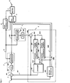
- Fig. 1 is a block diagram of an image coding apparatus in a first embodiment of the invention.
- Fig. 2 is an explanatory diagram showing the relation between the frame of motion image signal to be coded, and a frame of reproduction signal used for determining a predict signal, in the image coding apparatus of the first embodiment of the invention.
- Fig. 3 is a timing chart of the image coding apparatus of the first embodiment of the invention.
- Fig. 4 is a block diagram of image coding apparatuses in second and third embodiments of the invention.
- Fig. 5 is an explanatory diagram showing the relation between a frame of moving image signal to be coded, and a frame of reproduction signal used for determining a predict signal, in the image coding apparatus of the third embodiment of the invention.
- Fig. 1 is a block diagram of an image coding apparatus in a first embodiment of the invention.
- numeral 1 denotes an input of the image coding apparatus
- 2 is a predict error calculator
- 3 is a coder
- 4 is a decoder
- 5 is a predict signal calculator
- 6 is a variable length coder
- 7 is a buffer memory
- 8 is a rate controller
- 9 is an output of the image coding apparatus.
- Numeral 301 is a discrete cosine transform (DCT) circuit, and 302 is a quantizer, which are combined to compose the coder 3.
- Numeral 401 is a dequantizer, and 402 is an inverse discrete cosine transform (IDCT) circuit, which are combined to compose the decoder 4.
- Numeral 502 is an adder, 503 is a first frame memory, 504 is a second frame memory, 505 is a first motion compensator, 506 is a second motion compensator, 507 is an averager, and 508 is a motion estimator, which are combined to compose the predict signal calculator 5.
- Numeral 201 is a predict error signal produced by the predict error calculator 2
- 303 is a predict error code produced by the coder 3
- 403 is a reproduction predict error signal produced by the decoder 4
- 501 is a predict signal produced by the predict signal calculator 5
- 5021 is a reproduction signal produced by the adder 502
- 5051 is a first predict signal produced by the first motion compensator 505
- 5061 is a second predict signal produced by the second motion compensator 506
- 5081 is a first motion vector produced by the motion estimator 508,
- 5082 is a second motion vector produced by the motion estimator 508, and 81 is the quantizing step size produced by the rate controller 8.
- the motion image signal to be coded is entered in the input 1 of the image coding apparatus, and is fed into the predict error calculator 2 and the predict signal calculator 5.
- the predict error calculator 2 determines a difference of the motion image signal to be coded and the predict signal 501, and produces the result as the predict error signal 201.
- the coder 3 receives the predict error signal 201, processes it by DCT (discrete cosine transform) in the DCT circuit 301, quantizes the obtained DCT coefficient value in the quantizer 302 according to the value of the quantizing step size 81, and produces the predict error code 303.
- DCT discrete cosine transform
- the decoder 4 receives the predict error code 303, dequantizes it in the dequantizer 401 according to the value of the quantizing step size 81, processes the obtained DCT coefficient value by IDCT (inverse discrete cosine transform) in the IDCT circuit 402, and produces the reproduction predict error signal 403.
- the variable length coder 6 receives the quantizing step size 81, predict error code 303, first motion vector 5081, and second motion vector 5802, codes them in variable length, and writes the obtained data into the buffer memory 7. The data is read out of the buffer memory 7 at a specified rate, and produced into the output 9 of the image coding apparatus.
- the rate controller 8 controls the value of the quantizing step size 81 so that the amount of data remaining in the buffer memory 7 becomes a specified amount.
- the predict signal calculator 5 is a circuit for obtaining the predict signal 501.
- the adder 502 adds the reproduction predict error signal 403 and predict signal 501, and produces the reproduction signal 5021.
- the reproduction signal 5021 is stored in the first frame memory 503 and second frame memory 504 alternately on a frame by frame basis.
- the first motion compensator 505 compensates the motion of the reproduction signal read out from the first frame memory by the first motion vector 5081, and produces the first predict signal 5051.
- the second motion compensator 506 compensates the motion of the reproduction signal read out from the second frame memory 504 by the second motion vector 5082, and produces the second predict signal 5061.
- the averager 507 determines an average of the first predict signal 5051 and second predict signal 5061, and produces the predict signal 501.
- the motion estimator 508 determines and produces a motion vector of the image signal to be coded.
- the motion estimator 508 determines the motion vector between the image signal to be coded and the reproduction signal read out from the first frame memory 503, and produces the first motion vector 5081. It also determines the motion vector between the image signal to be coded and the reproduction signal read out from the second frame memory 504, and produces the second motion vector 5082.
- FIG. 2 is an explanatory diagram showing the relation between the frame of motion image signal to be coded, and the frame of reproduction signal used for determining the predict signal 501, in which f(n-2) to f(n+3) denote the (n-2)-th (n+3)-th frames of image signals.
- Fig. 2 (a) shows a case of coding the frame f(n), in which the predict signal is determined by motion compensation of the frame f(n-2) and frame f(n-1) of reproduction signals.
- Fig. 2 is an explanatory diagram showing the relation between the frame of motion image signal to be coded, and the frame of reproduction signal used for determining the predict signal 501, in which f(n-2) to f(n+3) denote the (n-2)-th (n+3)-th frames of image signals.
- Fig. 2 (a) shows a case of coding the frame f(n), in which the predict signal is determined by motion compensation of the frame f(n-2) and frame f(
- FIG. 2 (b) shows a case of coding the frame f(n+1), in which the predict signal is determined by motion compensation of the frame f(n-1) and frame f(n) of reproduction signals.
- Figs. 2 (c) and (d) show cases of coding the frame f(n+2) and frame f(n+3), respectively.
- Fig. 3 shows the timing chart of the image coding apparatus.
- (a) is an input signal of the image coding apparatus
- (b) is the reproduction signal written into the first frame memory 503
- (c) is the reproduction signal given to the first motion compensator 505 from the first frame memory 503
- (d) is the reproduction signal written into the second frame memory 504
- (e) is the reproduction signal given to the second motion compensator 506 from the second frame memory 504
- (f) is the predict signal 501.
- fr(n) is a frame of reproduction signal obtained by coding and decoding the frame f(n) of input signal
- fp(N) is a frame of predict signal for coding the frame f(n) of input signal.
- the reproduction signal 5021 is written into the first frame memory 503 and second frame memory 504 alternately on a frame by frame basis.
- the frame fr(n-2) of reproduction signal is read out from the first frame memory 503, and the motion Is compensated by the first motion compensator 505, so that the first predict signal 5051 is obtained.
- the frame fr(n-1) of reproduction signal is read out from the second frame memory 504, and the motion is compensated in the second motion compensator 506, so that the second predict signal 5061 is obtained.
- the averager 507 determines the average of the first predict signal 5051 and second predict signal 5061, and produces fp(n) as predict signal 501.
- the distortions contained in the first and second predict signals and are low in correlation are reduced by determining the average of the two predict signals.
- the distortion of predict signal is decreased, that is, the predict error is reduced, so that the coding efficiency is improved.
- the predict signal 501 was the average of two predict signals, that is, the first predict signal 5051 and second predict signal 5052. But instead, by compensating the motion of N (N being an integer of 2 or more) reproduction frames, the first to N-th predict signals can be determined, and the predict signal 501 can be obtained by a linear combination thereof.
- the distance between the frame to be coded and the frame of the first or second predict signal is one or two frames, but this distance is not limitative.
- Fig. 4 is a block diagram of an image coding apparatus in the second embodiment of the invention.
- numeral 509 is a predict mode decision circuit
- 510 is a predict signal selector
- 5071 is a third predict signal produced by an averager 507
- 5091 is a predict mode signal produced by the predict mode decision circuit 509.
- What is different from the first embodiment shown in Fig. 1 is the composition of the predict signal calculator 5 and the input of the predict mode signal 5091 in the variable length coder 6.
- the averager 507 determines an average of the first predict signal 5051 and second predict signal 5061, and produces the third predict signal 5071.
- the predict mode decision circuit 509 judges a smallest predict error out of the incoming first to third predict signals, and produces an index showing it as a predict mode signal 5091.
- the predict signal selector 510 selects one out of the first predict signal 5051, second predict signal 5061, and third predict signal 5071, depending on the predict mode signal 5091, and produces a selected signal as the predict signal 501.
- the predict signal 541 is the one having the smallest predict error out of the first to third predict signals.
- the predict mode signal 5091 is entered in the variable length coder 6, and is coded in variable length together with the quantizing step size 81, predict error code 303, first motion vector 5081, and second motion vector 5082.
- the predict mode decision circuit and predict signal selector by installing the predict mode decision circuit and predict signal selector, the one having the smallest predict error out of the first to third predict signals Is used as the predict signal, so that the distortion of the predict signal can be reduced more as compared with the case of using the average of the first and second predict signals.
- a block diagram of the third embodiment is the same as the second embodiment in Fig. 4. That is different from the second embodiment is that the motion image signal entering the input of the image coding apparatus is of interlaced scanning method.
- Fig. 5 is an explanatory diagram showing the relation between the frame of the motion image signal to be coded and the frame of reproduction signal used for determining the predict signal 501, in the image coding apparatus of the third embodiment of the invention.
- the n-th frame is composed of field f (n, 1) and field f (n, 2).
- FIG. 5 (a) shows a case of coding the field f(n, 1), in which the predict signal is determined by motion compensation of the field f(n-1, 1) and field f(n-1, 2) of reproduction signal.
- Fig. 5 (b) shows a case of coding the field (n, 2), in which the predict signal is determined by motion compensation of the field f(n-1, 1) and field f(n-1, 2) of reproduction signal.
- Figs. 5 (c) and (d) show cases of determining the field f(n+1, 1) and field f(n+1, 2).
- the distortion of the predict signal can be reduced in the same way as in the second embodiment.
- the first predict signal and second predict signal are reproduction signals which are different from each other in the type, an efficient prediction is realized for a moving image signal.
- the two fields used for determining the predict signal belong to one same field, but the two fields may also belong to different fields.
- the distance between the frame to be coded and the frame of the first or second predict signal is one frame, but this distance is not limitative.
Abstract
Description
- The present invention relates to an image coding method for high efficiency coding of motion image signals in transmission or recording of motion image signals and an apparatus for performing the method.
- In the image coding apparatus, recently, along with the development of television telephone and television conference system, various high efficiency coding technologies have been realized. In particular, the coding technology making use of the inter-frame predict coding is widely used in the image coding apparatus.
- The inter-frame predict coding system is to determine a predict signal by predicting a frame to be encoded from another frame, and encode a predict error which is a difference between the frame to be encoded and the predict signal. The predict signal is determined in the following manners. (1) A reproduction signal of a frame before the intended frame to be encoded is delivered from a memory of a local decoder, and it is compensated for motion to obtain a predict signal. (2) A reproduction signal of a frame before the intended frame to be encoded and a reproduction signal of a frame after the intended frame are delivered from memories of a local decoder, and after they are compensated for motion, a mean value of them is determined as a predict signal.
- In the method of (2), in other words, a frame located between two reproduction signals apart from each other by two frames or more is determined by motion compensating frame interpolation, and this frame is used as the predict signal. One of the prior arts of such image coding apparatus is disclosed in EP90304841. The conventional image coding apparatus is explained below.
- The motion picture signals entering the image coding apparatus are subjected to two types of predict methods alternately on a frame by frame basis. The predict method is the manner of determining the predict signal. The first predict method is to read the reproduction signal two frames before from a frame memory of a local decoder, and compensate it for motion to obtain a predict signal, and the second predict method is to determine an image signal by motion compensating frame interpolation from preceding and succeeding reproduction frames as a predict signal. Afterwards, a predict error signal is determined which is a difference between the frame to be encoded and the predict signal, and an encoded predict error signal is the output signal of the image coding apparatus. The image coding apparatus, possessing a local decoder, decodes the code, determines the reproduction image, and stores it in a frame memory.
- In such constitution, however, a reproduction frame later in time is needed when determining the predict signal from the reproduction frames before and after the frame to be coded, that is, the frame later in time must have been already coded. To realize this, it is necessary to change the time sequence of the frames of the motion picture signals entering the coding apparatus, and therefore the constitution of the coding apparatus is complicated.
- It is hence a primary object of the invention to raise the coding efficiency by reducing the distortion of predict signal, and to simplify the constitution of the coding apparatus.
- To achieve the above object, the invention presents an image coding method comprising the steps of compensating a motion of reproduction signals of N (N being an integer of 2 or more) frames positioned before a frame to be coded to obtain first to N-th predict signals, determining a linear combination of the first to N-th predict signals to obtain a predict signal, and coding a difference of the frame to be coded and the predict signal.
- The invention also presents an image coding apparatus comprising coding means for coding a difference of a frame to be coded and a predict signal to produce a predict error code, decoding means for decoding the predict error code to obtain a reproduction signal, memory means for storing the reproduction signal, motion compensating means for compensating a motion of N (N being an integer of 2 or more) frames before the frame to be coded in the reproduction signal stored in the memory means to obtain first to N-th predict signals, and linear combining means for determining a linear combination of the first to N-th predict signals to obtain the predict signal.
- Being thus composed, the invention is capable of determining N predict signals by compensating the motion of the reproduction signals of N frames preceding the frame to be coded, and determining the predict signal by linear combining of these predict signals, so that the distortion of predict signal can be reduced. As a result, the predict error signal becomes small, and the coding efficiency is improved.
- Fig. 1 is a block diagram of an image coding apparatus in a first embodiment of the invention.
- Fig. 2 is an explanatory diagram showing the relation between the frame of motion image signal to be coded, and a frame of reproduction signal used for determining a predict signal, in the image coding apparatus of the first embodiment of the invention.
- Fig. 3 is a timing chart of the image coding apparatus of the first embodiment of the invention.
- Fig. 4 is a block diagram of image coding apparatuses in second and third embodiments of the invention.
- Fig. 5 is an explanatory diagram showing the relation between a frame of moving image signal to be coded, and a frame of reproduction signal used for determining a predict signal, in the image coding apparatus of the third embodiment of the invention.
- Referring now to the drawings, an embodiment of an image coding apparatus of the invention is described in detail below. Fig. 1 is a block diagram of an image coding apparatus in a first embodiment of the invention. In Fig. 1,
numeral 1 denotes an input of the image coding apparatus, 2 is a predict error calculator, 3 is a coder, 4 is a decoder, 5 is a predict signal calculator, 6 is a variable length coder, 7 is a buffer memory, 8 is a rate controller, and 9 is an output of the image coding apparatus. - Numeral 301 is a discrete cosine transform (DCT) circuit, and 302 is a quantizer, which are combined to compose the
coder 3. Numeral 401 is a dequantizer, and 402 is an inverse discrete cosine transform (IDCT) circuit, which are combined to compose thedecoder 4. Numeral 502 is an adder, 503 is a first frame memory, 504 is a second frame memory, 505 is a first motion compensator, 506 is a second motion compensator, 507 is an averager, and 508 is a motion estimator, which are combined to compose the predict signal calculator 5. -
Numeral 201 is a predict error signal produced by thepredict error calculator coder decoder predict signal calculator 5, 5021 is a reproduction signal produced by theadder first motion compensator second motion compensator motion estimator motion estimator - In the thus composed image coding apparatus, the operation is described below while referring to Fig. 1. The motion image signal to be coded is entered in the
input 1 of the image coding apparatus, and is fed into thepredict error calculator 2 and the predict signal calculator 5. Thepredict error calculator 2 determines a difference of the motion image signal to be coded and thepredict signal 501, and produces the result as thepredict error signal 201. Thecoder 3 receives thepredict error signal 201, processes it by DCT (discrete cosine transform) in the DCT circuit 301, quantizes the obtained DCT coefficient value in thequantizer 302 according to the value of the quantizingstep size 81, and produces thepredict error code 303. Thedecoder 4 receives thepredict error code 303, dequantizes it in thedequantizer 401 according to the value of the quantizingstep size 81, processes the obtained DCT coefficient value by IDCT (inverse discrete cosine transform) in theIDCT circuit 402, and produces the reproduction predicterror signal 403. The variable length coder 6 receives the quantizingstep size 81, predicterror code 303,first motion vector 5081, and second motion vector 5802, codes them in variable length, and writes the obtained data into the buffer memory 7. The data is read out of the buffer memory 7 at a specified rate, and produced into the output 9 of the image coding apparatus. The rate controller 8 controls the value of the quantizingstep size 81 so that the amount of data remaining in the buffer memory 7 becomes a specified amount. - The predict signal calculator 5 is a circuit for obtaining the
predict signal 501. Theadder 502 adds the reproduction predicterror signal 403 and predictsignal 501, and produces thereproduction signal 5021. Thereproduction signal 5021 is stored in thefirst frame memory 503 andsecond frame memory 504 alternately on a frame by frame basis. Thefirst motion compensator 505 compensates the motion of the reproduction signal read out from the first frame memory by thefirst motion vector 5081, and produces the firstpredict signal 5051. Thesecond motion compensator 506 compensates the motion of the reproduction signal read out from thesecond frame memory 504 by thesecond motion vector 5082, and produces the secondpredict signal 5061. Theaverager 507 determines an average of the firstpredict signal 5051 and second predictsignal 5061, and produces thepredict signal 501. Themotion estimator 508 determines and produces a motion vector of the image signal to be coded. Themotion estimator 508 determines the motion vector between the image signal to be coded and the reproduction signal read out from thefirst frame memory 503, and produces thefirst motion vector 5081. It also determines the motion vector between the image signal to be coded and the reproduction signal read out from thesecond frame memory 504, and produces thesecond motion vector 5082. - Explained next is the relation between the frame of the motion image signal to be coded and the frame of the reproduction signal used for determining the
predict signal 501. Fig. 2 is an explanatory diagram showing the relation between the frame of motion image signal to be coded, and the frame of reproduction signal used for determining thepredict signal 501, in which f(n-2) to f(n+3) denote the (n-2)-th (n+3)-th frames of image signals. Fig. 2 (a) shows a case of coding the frame f(n), in which the predict signal is determined by motion compensation of the frame f(n-2) and frame f(n-1) of reproduction signals. Fig. 2 (b) shows a case of coding the frame f(n+1), in which the predict signal is determined by motion compensation of the frame f(n-1) and frame f(n) of reproduction signals. Figs. 2 (c) and (d) show cases of coding the frame f(n+2) and frame f(n+3), respectively. - The operation timing of the image coding apparatus is described below while referring to Fig. 3. Fig. 3 shows the timing chart of the image coding apparatus. In Fig. 3, (a) is an input signal of the image coding apparatus, (b) is the reproduction signal written into the
first frame memory 503, (c) is the reproduction signal given to thefirst motion compensator 505 from thefirst frame memory 503, (d) is the reproduction signal written into thesecond frame memory 504, (e) is the reproduction signal given to thesecond motion compensator 506 from thesecond frame memory 504, and (f) is thepredict signal 501. Besides, fr(n) is a frame of reproduction signal obtained by coding and decoding the frame f(n) of input signal, and fp(N) is a frame of predict signal for coding the frame f(n) of input signal. - The
reproduction signal 5021 is written into thefirst frame memory 503 andsecond frame memory 504 alternately on a frame by frame basis. When the frame f(n) is entered in theinput 1 of the image coding apparatus as input signal, the frame fr(n-2) of reproduction signal is read out from thefirst frame memory 503, and the motion Is compensated by thefirst motion compensator 505, so that the firstpredict signal 5051 is obtained. At the same time, the frame fr(n-1) of reproduction signal is read out from thesecond frame memory 504, and the motion is compensated in thesecond motion compensator 506, so that the secondpredict signal 5061 is obtained. Theaverager 507 determines the average of the firstpredict signal 5051 and second predictsignal 5061, and produces fp(n) as predictsignal 501. - In this way, since the average of the first and second predict signals Is used as the predict signal, the distortions contained in the first and second predict signals and are low in correlation are reduced by determining the average of the two predict signals. Thus, the distortion of predict signal is decreased, that is, the predict error is reduced, so that the coding efficiency is improved.
- In the first embodiment, meanwhile, the predict signal 501 was the average of two predict signals, that is, the first predict
signal 5051 and second predict signal 5052. But instead, by compensating the motion of N (N being an integer of 2 or more) reproduction frames, the first to N-th predict signals can be determined, and the predict signal 501 can be obtained by a linear combination thereof. - In the first embodiment, moreover, the distance between the frame to be coded and the frame of the first or second predict signal is one or two frames, but this distance is not limitative.
- A second embodiment of the invention is described below while referring to the accompanying drawings.
- Fig. 4 is a block diagram of an image coding apparatus in the second embodiment of the invention. In Fig. 4, numeral 509 is a predict mode decision circuit, 510 is a predict signal selector, 5071 is a third predict signal produced by an
averager mode decision circuit 509. What is different from the first embodiment shown in Fig. 1 is the composition of the predict signal calculator 5 and the input of the predictmode signal 5091 in the variable length coder 6. - In the thus composed image coding apparatus, the operation is explained below while referring to Fig. 4.
- The
averager 507 determines an average of the first predictsignal 5051 and second predictsignal 5061, and produces the third predictsignal 5071. The predictmode decision circuit 509 judges a smallest predict error out of the incoming first to third predict signals, and produces an index showing it as a predictmode signal 5091. The predictsignal selector 510 selects one out of the first predictsignal 5051, second predictsignal 5061, and third predictsignal 5071, depending on the predictmode signal 5091, and produces a selected signal as the predict signal 501. The predict signal 541 is the one having the smallest predict error out of the first to third predict signals. Besides, the predictmode signal 5091 is entered in the variable length coder 6, and is coded in variable length together with the quantizingstep size 81, predicterror code 303,first motion vector 5081, andsecond motion vector 5082. - Thus, according to the second embodiment, by installing the predict mode decision circuit and predict signal selector, the one having the smallest predict error out of the first to third predict signals Is used as the predict signal, so that the distortion of the predict signal can be reduced more as compared with the case of using the average of the first and second predict signals.
- A third embodiment is explained below.
- A block diagram of the third embodiment is the same as the second embodiment in Fig. 4. That is different from the second embodiment is that the motion image signal entering the input of the image coding apparatus is of interlaced scanning method. Fig. 5 is an explanatory diagram showing the relation between the frame of the motion image signal to be coded and the frame of reproduction signal used for determining the predict
signal 501, in the image coding apparatus of the third embodiment of the invention. In the third embodiment, since the image signal to be coded is of interlaced scanning method, the n-th frame is composed of field f (n, 1) and field f (n, 2). Fig. 5 (a) shows a case of coding the field f(n, 1), in which the predict signal is determined by motion compensation of the field f(n-1, 1) and field f(n-1, 2) of reproduction signal. Fig. 5 (b) shows a case of coding the field (n, 2), in which the predict signal is determined by motion compensation of the field f(n-1, 1) and field f(n-1, 2) of reproduction signal. Figs. 5 (c) and (d) show cases of determining the field f(n+1, 1) and field f(n+1, 2). - Thus, also when the motion image signal of interlaced scanning method is coded by the coding apparatus in the third embodiment, the distortion of the predict signal can be reduced in the same way as in the second embodiment. Furthermore, since the first predict signal and second predict signal are reproduction signals which are different from each other in the type, an efficient prediction is realized for a moving image signal.
- In the third embodiment, the two fields used for determining the predict signal belong to one same field, but the two fields may also belong to different fields.
- In the third embodiment, moreover, the distance between the frame to be coded and the frame of the first or second predict signal is one frame, but this distance is not limitative.
Claims (10)
- An image coding method comprising the steps of:
compensating a motion of reproduction signals of N (N being an integer of 2 or more) frames positioned before a frame to be coded to obtain first to N-th predict signals;
determining a linear combination of the first to N-th predict signals to obtain a predict signal; and
coding a difference of the frame to be coded and the predict signal. - An image coding method comprising the steps of:
compensating a motion of reproduction signals of two frames positioned before a frame to be coded to obtain a first predict signal and a second predict signal;
determining an average of the first predict signal and the second predict signal to obtain a predict signal; and
coding a difference of the frame to be coded and the predict signal. - An image coding method comprising the steps of:
compensating a motion of reproduction signals of two frames positioned before a frame to be coded to obtain a first predict signal and a second predict signal;
determining an average of the first predict signal and the second predict signal to obtain a third predict signal;
determining a size of a predict error of the first, second and third predict signal in each block composed of a set of plural pixels;
selecting one having a smallest predict error out of the first, second and third predict signals to obtain a predict signal; and
coding a difference of the frame to be coded and the predict signal. - An image coding method comprising the steps of:
compensating a motion of reproduction signals of two frames positioned before a frame to be coded to obtain a first predict signal and a second predict signal;
determining an average of the first predict signal and the second predict signal to obtain a third predict signal;
selecting one out of two or more predict signals including the third predict signal to obtain a predict signal; and
coding a difference of the predict signal and the frame to be coded. - An image coding apparatus comprising:
coding means for coding a difference of a frame to be coded and a predict signal to produce a predict error code;
decoding means for decoding the predict error code to obtain a reproduction signal;
memory means for storing the reproduction signal;
motion compensating means for compensating a motion of N (N being an integer of 2 or more) frames before the frame to be coded in the reproduction signal stored in the memory means to obtain first to N-th predict signals; and
linear combining means for determining a linear combination of the first to N-th predict signals to obtain the predict signal. - An image coding apparatus comprising:
coding means for coding a difference of a frame to be coded and a predict signal to produce a predict error code;
decoding means for decoding the predict error code to obtain a reproduction signal;
memory means for storing the reproduction signal;
motion compensating means for compensating a motion of N (N being an integer of 2 or more) frames before the frame to be coded in the reproduction signal stored in the memory means to obtain first to N-th predict signals;
linear combining means for determining a linear combination of the first to the N-th predict signals to obtain a predict signal of a linear combination; and
selector means for selecting one out of two or more predict signals including the predict signal of linear combination to obtain the predict signal. - An image coding apparatus comprising:
predict error calculating means for producing a difference of a frame to be coded and a predict signal as a predict error signal;
coding means for coding the predict error signal to produce a predict error code;
decoding means for decoding the predict error code to obtain a reproduction signal;
memory means for storing the reproduction signal;
compensating means for compensating a motion of two frames positioned before the frame to be coded in the reproduction signal stored in the memory means to obtain a first predict signal and a second predict signal;
averaging means for determining an average of the first predict signal and the second predict signal to obtain a third predict signal; and
predict error calculating means for determining a size of a predict error of the first, second and third predict signals in every block which is a set of plural pixels; and
means for selecting one having a smallest predict error out of the first, second and third predict signals as the predict signal. - An image coding apparatus comprising:
predict error calculating means for producing a difference of a frame to be coded and a predict signal as a predict error signal;
coding means for coding the predict error signal to produce a predict error code;
decoding means for decoding the predict error code to obtain a reproduction signal;
memory means for storing the reproduction signal;
compensating means for compensating a motion of two frames positioned before the frame to be coded in the reproduction signal stored in the memory means to obtain a first predict signal and a second predict signal;
averaging means for determining an average of the first predict signal and the second predict signal to obtain a third predict signal; and
selector means for selecting one out of two or more predict signals including the third predict signal to obtain the predict signal. - An image coding apparatus for coding a motion image signal of interlaced scanning method, comprising:
predict error calculating means for producing a difference of a field to be coded and a predict signal as a predict error signal;
coding means for coding the predict error signal to produce a predict error code;
decoding means for decoding the predict error code to obtain a reproduction signal;
memory means for storing the reproduction signal;
motion compensating means for compensating a motion of a first field and a second field positioned before the field to be coded in the reproduction signal stored in the memory means to obtain a first predict signal and a second predict signal;
averaging means for determining an average of the first predict signal and the second predict signal to obtain a third predict signal; and
predict error calculating means for determining a size of a predict error of the first, second and third predict signals in every block which is a set of plural pixels; and
means for selecting one having a smallest predict error out of the first, second and third predict signals as the predict signal. - An image coding apparatus for coding a motion image signal of interlaced scanning method, comprising:
predict error calculating means for producing a difference of a field to be coded and a predict signal as a predict error signal;
coding means for coding the predict error signal to produce a predict error code;
decoding means for decoding the predict error code to obtain a reproduction signal;
memory means for storing the reproduction signal;
motion compensating means for compensating a motion of a first field and a second field positioned before the field to be coded in the reproduction signal stored in the memory means to obtain a first predict signal and a second predict signal;
averaging means for determining an average of the first predict signal and the second predict signal to obtain a third predict signal; and
selector means for selecting one out of two or more predict signals including the third predict signal to obtain the predict signal.
Applications Claiming Priority (2)
| Application Number | Priority Date | Filing Date | Title |
|---|---|---|---|
| JP191603/91 | 1991-07-31 | ||
| JP19160391A JP2699703B2 (en) | 1991-07-31 | 1991-07-31 | Motion compensation prediction method and image signal encoding method using the same |
Publications (3)
| Publication Number | Publication Date |
|---|---|
| EP0526163A2 true EP0526163A2 (en) | 1993-02-03 |
| EP0526163A3 EP0526163A3 (en) | 1993-09-29 |
| EP0526163B1 EP0526163B1 (en) | 1998-03-04 |
Family
ID=16277387
Family Applications (1)
| Application Number | Title | Priority Date | Filing Date |
|---|---|---|---|
| EP19920306876 Expired - Lifetime EP0526163B1 (en) | 1991-07-31 | 1992-07-28 | Image coding method and image coding apparatus |
Country Status (3)
| Country | Link |
|---|---|
| US (1) | US5412430A (en) |
| EP (1) | EP0526163B1 (en) |
| JP (1) | JP2699703B2 (en) |
Cited By (14)
| Publication number | Priority date | Publication date | Assignee | Title |
|---|---|---|---|---|
| EP0529587A2 (en) * | 1991-08-29 | 1993-03-03 | Sharp Kabushiki Kaisha | Image encoding apparatus |
| WO1994018794A1 (en) * | 1993-02-12 | 1994-08-18 | Thomson-Csf | Reduced throughput image recording method and device therefor |
| EP0676900A2 (en) * | 1994-04-11 | 1995-10-11 | General Instrument Corporation Of Delaware | Motion compensation for interlaced digital video signals |
| EP0866622A2 (en) * | 1997-03-21 | 1998-09-23 | Trw Inc. | Video data compression method |
| EP1012089B1 (en) * | 1997-09-12 | 2002-06-26 | Netra Systems | Pneumatic conveyor for articles, with transporting case, for minimising the level of contamination of articles, and method for cleaning such a conveyor |
| EP1406449A2 (en) * | 2002-08-31 | 2004-04-07 | Samsung Electronics Co., Ltd. | Interpolation apparatus and method for motion compensation |
| US7209520B2 (en) | 2001-10-17 | 2007-04-24 | Matsushita Electric Industrial Co., Ltd. | Moving picture encoding method and moving picture decoding method |
| US7224731B2 (en) | 2002-06-28 | 2007-05-29 | Microsoft Corporation | Motion estimation/compensation for screen capture video |
| US7394853B2 (en) | 2002-04-23 | 2008-07-01 | Matsushita Electric Industrial Co., Ltd. | Motion vector coding method and motion vector decoding method |
| EP2129133A3 (en) * | 1995-08-29 | 2012-02-15 | Sharp Kabushiki Kaisha | Video coding device and video decoding device with a motion compensated interframe prediction |
| US9888237B2 (en) | 2002-01-25 | 2018-02-06 | Microsoft Technology Licensing, Llc | Video coding |
| US10063863B2 (en) | 2003-07-18 | 2018-08-28 | Microsoft Technology Licensing, Llc | DC coefficient signaling at small quantization step sizes |
| US10116959B2 (en) | 2002-06-03 | 2018-10-30 | Microsoft Technology Licesning, LLC | Spatiotemporal prediction for bidirectionally predictive (B) pictures and motion vector prediction for multi-picture reference motion compensation |
| US10554985B2 (en) | 2003-07-18 | 2020-02-04 | Microsoft Technology Licensing, Llc | DC coefficient signaling at small quantization step sizes |
Families Citing this family (56)
| Publication number | Priority date | Publication date | Assignee | Title |
|---|---|---|---|---|
| JPH0583700A (en) * | 1991-09-18 | 1993-04-02 | Nec Corp | Dpcm forecasting coding circuit |
| JP2586260B2 (en) * | 1991-10-22 | 1997-02-26 | 三菱電機株式会社 | Adaptive blocking image coding device |
| KR0126657B1 (en) * | 1993-10-28 | 1997-12-29 | 구자홍 | Moving compensation device for digital image recovery |
| US6798834B1 (en) | 1996-08-15 | 2004-09-28 | Mitsubishi Denki Kabushiki Kaisha | Image coding apparatus with segment classification and segmentation-type motion prediction circuit |
| JP2870415B2 (en) * | 1994-08-22 | 1999-03-17 | 日本電気株式会社 | Area division method and apparatus |
| US5886744A (en) * | 1995-09-08 | 1999-03-23 | Intel Corporation | Method and apparatus for filtering jitter from motion estimation video data |
| US5699129A (en) * | 1995-10-17 | 1997-12-16 | Zapex Technologies, Inc. | Method and apparatus for motion vector determination range expansion |
| KR100387229B1 (en) * | 1995-11-01 | 2003-08-21 | 삼성전자주식회사 | Apparatus for encoding images |
| KR100355375B1 (en) * | 1995-11-01 | 2002-12-26 | 삼성전자 주식회사 | Method and circuit for deciding quantizing interval in video encoder |
| EP1343328A3 (en) * | 1996-02-07 | 2005-02-09 | Sharp Kabushiki Kaisha | Moving image encoding and decoding device |
| DE19630295A1 (en) * | 1996-07-26 | 1998-01-29 | Thomson Brandt Gmbh | Method for coding and decoding digitized pictures of an animated film and device for coding and decoding digitized pictures of an animated film |
| US7046734B2 (en) * | 1998-04-02 | 2006-05-16 | Intel Corporation | Method and apparatus for performing real-time data encoding |
| US6904174B1 (en) | 1998-12-11 | 2005-06-07 | Intel Corporation | Simplified predictive video encoder |
| US6408029B1 (en) | 1998-04-02 | 2002-06-18 | Intel Corporation | Method and apparatus for simplifying real-time data encoding |
| JP4264571B2 (en) * | 1998-04-09 | 2009-05-20 | ソニー株式会社 | Digital image decoding apparatus and method, and recording medium |
| US6983018B1 (en) | 1998-11-30 | 2006-01-03 | Microsoft Corporation | Efficient motion vector coding for video compression |
| US6499060B1 (en) | 1999-03-12 | 2002-12-24 | Microsoft Corporation | Media coding for loss recovery with remotely predicted data units |
| JP2001045494A (en) * | 2000-01-01 | 2001-02-16 | Mitsubishi Electric Corp | Image encoding device |
| KR20020011247A (en) * | 2000-08-01 | 2002-02-08 | 구자홍 | Apparatus and method for increasing definition of digital television |
| US7266150B2 (en) | 2001-07-11 | 2007-09-04 | Dolby Laboratories, Inc. | Interpolation of video compression frames |
| US8111754B1 (en) | 2001-07-11 | 2012-02-07 | Dolby Laboratories Licensing Corporation | Interpolation of video compression frames |
| KR20060111735A (en) * | 2002-01-18 | 2006-10-27 | 가부시끼가이샤 도시바 | Video decoding method and apparatus |
| JP2004007379A (en) * | 2002-04-10 | 2004-01-08 | Toshiba Corp | Method for encoding moving image and method for decoding moving image |
| WO2003098939A1 (en) * | 2002-05-22 | 2003-11-27 | Matsushita Electric Industrial Co., Ltd. | Moving image encoding method, moving image decoding method, and data recording medium |
| US7280700B2 (en) * | 2002-07-05 | 2007-10-09 | Microsoft Corporation | Optimization techniques for data compression |
| US7154952B2 (en) | 2002-07-19 | 2006-12-26 | Microsoft Corporation | Timestamp-independent motion vector prediction for predictive (P) and bidirectionally predictive (B) pictures |
| US7426308B2 (en) * | 2003-07-18 | 2008-09-16 | Microsoft Corporation | Intraframe and interframe interlace coding and decoding |
| US20050013498A1 (en) | 2003-07-18 | 2005-01-20 | Microsoft Corporation | Coding of motion vector information |
| US7499495B2 (en) * | 2003-07-18 | 2009-03-03 | Microsoft Corporation | Extended range motion vectors |
| US7609763B2 (en) * | 2003-07-18 | 2009-10-27 | Microsoft Corporation | Advanced bi-directional predictive coding of video frames |
| US7599438B2 (en) * | 2003-09-07 | 2009-10-06 | Microsoft Corporation | Motion vector block pattern coding and decoding |
| US8085844B2 (en) * | 2003-09-07 | 2011-12-27 | Microsoft Corporation | Signaling reference frame distances |
| US7577198B2 (en) * | 2003-09-07 | 2009-08-18 | Microsoft Corporation | Number of reference fields for an interlaced forward-predicted field |
| US7623574B2 (en) | 2003-09-07 | 2009-11-24 | Microsoft Corporation | Selecting between dominant and non-dominant motion vector predictor polarities |
| US8064520B2 (en) * | 2003-09-07 | 2011-11-22 | Microsoft Corporation | Advanced bi-directional predictive coding of interlaced video |
| US7567617B2 (en) | 2003-09-07 | 2009-07-28 | Microsoft Corporation | Predicting motion vectors for fields of forward-predicted interlaced video frames |
| US7317839B2 (en) * | 2003-09-07 | 2008-01-08 | Microsoft Corporation | Chroma motion vector derivation for interlaced forward-predicted fields |
| US7616692B2 (en) | 2003-09-07 | 2009-11-10 | Microsoft Corporation | Hybrid motion vector prediction for interlaced forward-predicted fields |
| US7724827B2 (en) | 2003-09-07 | 2010-05-25 | Microsoft Corporation | Multi-layer run level encoding and decoding |
| US7577200B2 (en) | 2003-09-07 | 2009-08-18 | Microsoft Corporation | Extended range variable length coding/decoding of differential motion vector information |
| US7620106B2 (en) | 2003-09-07 | 2009-11-17 | Microsoft Corporation | Joint coding and decoding of a reference field selection and differential motion vector information |
| CN1823531B (en) * | 2003-12-22 | 2010-05-26 | 日本电气株式会社 | Method and apparatus for encoding moving pictures |
| JP4414904B2 (en) | 2004-04-16 | 2010-02-17 | 株式会社エヌ・ティ・ティ・ドコモ | Moving picture encoding apparatus, moving picture encoding method, moving picture encoding program, moving picture decoding apparatus, moving picture decoding method, and moving picture decoding program |
| US8634413B2 (en) * | 2004-12-30 | 2014-01-21 | Microsoft Corporation | Use of frame caching to improve packet loss recovery |
| US7403562B2 (en) * | 2005-03-09 | 2008-07-22 | Eg Technology, Inc. | Model based rate control for predictive video encoder |
| US9077960B2 (en) | 2005-08-12 | 2015-07-07 | Microsoft Corporation | Non-zero coefficient block pattern coding |
| US20070116117A1 (en) * | 2005-11-18 | 2007-05-24 | Apple Computer, Inc. | Controlling buffer states in video compression coding to enable editing and distributed encoding |
| US8780997B2 (en) | 2005-11-18 | 2014-07-15 | Apple Inc. | Regulation of decode-side processing based on perceptual masking |
| US8233535B2 (en) | 2005-11-18 | 2012-07-31 | Apple Inc. | Region-based processing of predicted pixels |
| US8031777B2 (en) | 2005-11-18 | 2011-10-04 | Apple Inc. | Multipass video encoding and rate control using subsampling of frames |
| US8295343B2 (en) * | 2005-11-18 | 2012-10-23 | Apple Inc. | Video bit rate control method |
| US8254455B2 (en) | 2007-06-30 | 2012-08-28 | Microsoft Corporation | Computing collocated macroblock information for direct mode macroblocks |
| US7925774B2 (en) | 2008-05-30 | 2011-04-12 | Microsoft Corporation | Media streaming using an index file |
| CN102113326A (en) | 2008-08-04 | 2011-06-29 | 杜比实验室特许公司 | Overlapped block disparity estimation and compensation architecture |
| US8189666B2 (en) | 2009-02-02 | 2012-05-29 | Microsoft Corporation | Local picture identifier and computation of co-located information |
| JP6453652B2 (en) * | 2015-01-09 | 2019-01-16 | 株式会社東芝 | Video transmission system |
Citations (3)
| Publication number | Priority date | Publication date | Assignee | Title |
|---|---|---|---|---|
| US4703351A (en) * | 1984-08-22 | 1987-10-27 | Sony Corporation | Apparatus for an efficient coding of television signals |
| EP0395440A2 (en) * | 1989-04-27 | 1990-10-31 | Victor Company Of Japan, Limited | Apparatus for adaptive interframe predictive encoding of video signal |
| EP0424026A2 (en) * | 1989-10-14 | 1991-04-24 | Sony Corporation | Video signal transmitting system |
Family Cites Families (3)
| Publication number | Priority date | Publication date | Assignee | Title |
|---|---|---|---|---|
| US4833535A (en) * | 1987-02-04 | 1989-05-23 | Kabushiki Kaisha Toshiba | Image transmission apparatus |
| JP2864725B2 (en) * | 1990-11-20 | 1999-03-08 | ソニー株式会社 | High-efficiency coding device for image signals |
| JPH04268892A (en) * | 1991-02-22 | 1992-09-24 | Mitsubishi Electric Corp | Inter-frame adaptive prediction encoding system |
-
1991
- 1991-07-31 JP JP19160391A patent/JP2699703B2/en not_active Expired - Lifetime
-
1992
- 1992-07-28 EP EP19920306876 patent/EP0526163B1/en not_active Expired - Lifetime
-
1994
- 1994-05-04 US US08/238,334 patent/US5412430A/en not_active Expired - Lifetime
Patent Citations (3)
| Publication number | Priority date | Publication date | Assignee | Title |
|---|---|---|---|---|
| US4703351A (en) * | 1984-08-22 | 1987-10-27 | Sony Corporation | Apparatus for an efficient coding of television signals |
| EP0395440A2 (en) * | 1989-04-27 | 1990-10-31 | Victor Company Of Japan, Limited | Apparatus for adaptive interframe predictive encoding of video signal |
| EP0424026A2 (en) * | 1989-10-14 | 1991-04-24 | Sony Corporation | Video signal transmitting system |
Non-Patent Citations (2)
| Title |
|---|
| IEEE TRANSACTIONS ON COMMUNICATIONS vol. 35, no. 6, June 1987, pages 637 - 645 MURAKAMI ET AL. '15/30 Mbits/s Universal Digital TV Codec Using a Median Adaptive Predictive Coding Method' * |
| SIGNAL PROCESSING : IMAGE COMMUNICATION vol. 2, no. 2, August 1990, AMSTERDAM pages 127 - 144 PURI ET AL. 'Video coding with motion-compensated interpolation for CD-ROM applications' * |
Cited By (52)
| Publication number | Priority date | Publication date | Assignee | Title |
|---|---|---|---|---|
| US5481310A (en) * | 1991-08-29 | 1996-01-02 | Sharp Kabushiki Kaisha | Image encoding apparatus |
| EP0529587A3 (en) * | 1991-08-29 | 1994-04-06 | Sharp Kk | |
| EP0529587A2 (en) * | 1991-08-29 | 1993-03-03 | Sharp Kabushiki Kaisha | Image encoding apparatus |
| WO1994018794A1 (en) * | 1993-02-12 | 1994-08-18 | Thomson-Csf | Reduced throughput image recording method and device therefor |
| FR2701623A1 (en) * | 1993-02-12 | 1994-08-19 | Thomson Csf | Method of recording reduced-rate images and device for implementing it. |
| EP0676900A3 (en) * | 1994-04-11 | 1998-04-08 | General Instrument Corporation Of Delaware | Motion compensation for interlaced digital video signals |
| EP1309199A2 (en) * | 1994-04-11 | 2003-05-07 | General Instrument Corporation | Motion compensation for interlaced digital video signals |
| EP1309199A3 (en) * | 1994-04-11 | 2003-12-10 | General Instrument Corporation | Motion compensation for interlaced digital video signals |
| EP0676900A2 (en) * | 1994-04-11 | 1995-10-11 | General Instrument Corporation Of Delaware | Motion compensation for interlaced digital video signals |
| EP2129133A3 (en) * | 1995-08-29 | 2012-02-15 | Sharp Kabushiki Kaisha | Video coding device and video decoding device with a motion compensated interframe prediction |
| EP0866622A2 (en) * | 1997-03-21 | 1998-09-23 | Trw Inc. | Video data compression method |
| EP0866622A3 (en) * | 1997-03-21 | 2001-03-14 | Trw Inc. | Video data compression method |
| EP1012089B1 (en) * | 1997-09-12 | 2002-06-26 | Netra Systems | Pneumatic conveyor for articles, with transporting case, for minimising the level of contamination of articles, and method for cleaning such a conveyor |
| US7209520B2 (en) | 2001-10-17 | 2007-04-24 | Matsushita Electric Industrial Co., Ltd. | Moving picture encoding method and moving picture decoding method |
| US8170103B2 (en) | 2001-10-17 | 2012-05-01 | Panasonic Corporation | Moving picture coding method and moving picture decoding method |
| US10257537B2 (en) | 2001-10-17 | 2019-04-09 | Panasonic Intellectual Property Corporation Of America | Moving picture coding method and moving picture decoding method |
| US9924195B2 (en) | 2001-10-17 | 2018-03-20 | Panasonic Intellectual Property Corporation Of America | Moving picture coding method and moving picture decoding method |
| US7526026B2 (en) | 2001-10-17 | 2009-04-28 | Panasonic Corporation | Moving picture coding method and moving picture decoding method |
| US7580459B2 (en) | 2001-10-17 | 2009-08-25 | Panasonic Corporation | Moving picture coding method and moving picture decoding method |
| US9900616B2 (en) | 2001-10-17 | 2018-02-20 | Panasonic Intellectual Property Corporation Of America | Moving picture coding method and moving picture decoding method |
| US7693217B2 (en) | 2001-10-17 | 2010-04-06 | Panasonic Corporation | Moving picture coding method and moving picture decoding method |
| US8064519B2 (en) | 2001-10-17 | 2011-11-22 | Panasonic Corporation | Moving picture coding method and moving picture decoding method |
| US8831100B2 (en) | 2001-10-17 | 2014-09-09 | Panasonic Intellectual Property Corporation Of America | Moving picture coding method and moving picture decoding method |
| US8179966B2 (en) | 2001-10-17 | 2012-05-15 | Panasonic Corporation | Moving picture coding method and moving picture decoding method |
| US9197894B2 (en) | 2001-10-17 | 2015-11-24 | Panasonic Intellectual Property Corporation Of America | Moving picture coding method and moving picture decoding method |
| US9191669B2 (en) | 2001-10-17 | 2015-11-17 | Panasonic Intellectual Property Corporation Of America | Moving picture coding method and moving picture decoding method |
| US8391361B2 (en) | 2001-10-17 | 2013-03-05 | Panasonic Corporation | Moving picture coding method and moving picture decoding method |
| US10582216B2 (en) | 2001-10-17 | 2020-03-03 | Panasonic Intellectual Property Corporation Of America | Moving picture coding method and moving picture decoding method |
| US9888237B2 (en) | 2002-01-25 | 2018-02-06 | Microsoft Technology Licensing, Llc | Video coding |
| US10284843B2 (en) | 2002-01-25 | 2019-05-07 | Microsoft Technology Licensing, Llc | Video coding |
| US9031132B2 (en) | 2002-04-23 | 2015-05-12 | Tagivan Ii Llc | Motion vector coding and decoding methods |
| US8155200B2 (en) | 2002-04-23 | 2012-04-10 | Panasonic Corporation | Motion vector coding and decoding method |
| US8665961B2 (en) | 2002-04-23 | 2014-03-04 | Panasonic Corporation | Motion vector coding and decoding methods |
| US8194745B2 (en) | 2002-04-23 | 2012-06-05 | Panasonic Corporation | Motion vector coding and decoding methods |
| US9020037B2 (en) | 2002-04-23 | 2015-04-28 | Tagivan Ii Llc | Motion vector coding and decoding methods |
| US9020034B2 (en) | 2002-04-23 | 2015-04-28 | Tagivan Ii Llc | Motion vector coding and decoding methods |
| US9020035B2 (en) | 2002-04-23 | 2015-04-28 | Tagivan Ii Llc | Motion vector coding and decoding methods |
| US9020036B2 (en) | 2002-04-23 | 2015-04-28 | Tagivan Ii Llc | Motion vector coding and decoding methods |
| US8179968B2 (en) | 2002-04-23 | 2012-05-15 | Panasonic Corporation | Motion vector coding and decoding methods |
| US9118930B2 (en) | 2002-04-23 | 2015-08-25 | Tagivan Ii Llc | Motion vector coding and decoding methods |
| US8160147B2 (en) | 2002-04-23 | 2012-04-17 | Panasonic Corporation | Motion vector coding and decoding methods |
| US8213510B2 (en) | 2002-04-23 | 2012-07-03 | Panasonic Corporation | Motion vector coding and decoding methods |
| US8155201B2 (en) | 2002-04-23 | 2012-04-10 | Panasonic Corporation | Motion vector coding and decoding methods |
| KR100947692B1 (en) | 2002-04-23 | 2010-03-16 | 파나소닉 주식회사 | Motion vector coding method and motion vector decoding method |
| US7394853B2 (en) | 2002-04-23 | 2008-07-01 | Matsushita Electric Industrial Co., Ltd. | Motion vector coding method and motion vector decoding method |
| US10116959B2 (en) | 2002-06-03 | 2018-10-30 | Microsoft Technology Licesning, LLC | Spatiotemporal prediction for bidirectionally predictive (B) pictures and motion vector prediction for multi-picture reference motion compensation |
| US7224731B2 (en) | 2002-06-28 | 2007-05-29 | Microsoft Corporation | Motion estimation/compensation for screen capture video |
| EP1406449A3 (en) * | 2002-08-31 | 2005-08-10 | Samsung Electronics Co., Ltd. | Interpolation apparatus and method for motion compensation |
| EP1406449A2 (en) * | 2002-08-31 | 2004-04-07 | Samsung Electronics Co., Ltd. | Interpolation apparatus and method for motion compensation |
| US10063863B2 (en) | 2003-07-18 | 2018-08-28 | Microsoft Technology Licensing, Llc | DC coefficient signaling at small quantization step sizes |
| US10554985B2 (en) | 2003-07-18 | 2020-02-04 | Microsoft Technology Licensing, Llc | DC coefficient signaling at small quantization step sizes |
| US10659793B2 (en) | 2003-07-18 | 2020-05-19 | Microsoft Technology Licensing, Llc | DC coefficient signaling at small quantization step sizes |
Also Published As
| Publication number | Publication date |
|---|---|
| EP0526163B1 (en) | 1998-03-04 |
| JPH0537915A (en) | 1993-02-12 |
| US5412430A (en) | 1995-05-02 |
| EP0526163A3 (en) | 1993-09-29 |
| JP2699703B2 (en) | 1998-01-19 |
Similar Documents
| Publication | Publication Date | Title |
|---|---|---|
| US5412430A (en) | Image coding method and image coding apparatus | |
| KR100314116B1 (en) | A motion-compensated coder with motion vector accuracy controlled, a decoder, a method of motion-compensated coding, and a method of decoding | |
| US6226327B1 (en) | Video coding method and apparatus which select between frame-based and field-based predictive modes | |
| EP0676900B1 (en) | Motion compensation for interlaced digital video signals | |
| EP0397402B1 (en) | Moving image signal encoding- and decoding apparatus | |
| JP3888597B2 (en) | Motion compensation coding apparatus and motion compensation coding / decoding method | |
| USRE40679E1 (en) | Picture encoding method, picture encoding apparatus and picture recording medium | |
| JP3856262B2 (en) | Motion compensation encoding apparatus, motion compensation encoding method, and motion compensation code recording medium | |
| EP0595599B1 (en) | Compression/decompression system for image data | |
| US6040864A (en) | Motion vector detector and video coder | |
| US4942465A (en) | Method of coding a digital video signal for reverse reproduction of pictures | |
| US5784107A (en) | Method and apparatus for picture coding and method and apparatus for picture decoding | |
| EP1445962A1 (en) | Adaptive variable-length coding and decoding methods for image data | |
| EP0485230A2 (en) | Moving picture signal progressive coding system | |
| US6415055B1 (en) | Moving image encoding method and apparatus, and moving image decoding method and apparatus | |
| US20060093039A1 (en) | Video image encoding method and video image encoding apparatus | |
| US5241401A (en) | Image signal encoding apparatus and method for controlling quantization step size in accordance with frame skip numbers | |
| US5689307A (en) | Encoding and decoding systems for transmitting moving pictures | |
| US20070140345A1 (en) | Motion estimation with motion vector penalty | |
| US6795498B1 (en) | Decoding apparatus, decoding method, encoding apparatus, encoding method, image processing system, and image processing method | |
| US5929913A (en) | Motion vector detector and video coder | |
| US5396292A (en) | Encoding apparatus for motion video signals | |
| US5610660A (en) | Multiplexing system for inserting synchronous words to picture image coded data | |
| US5394190A (en) | Video signal encoding apparatus | |
| EP0981251A1 (en) | Method and apparatus for video coding at high efficiency |
Legal Events
| Date | Code | Title | Description |
|---|---|---|---|
| PUAI | Public reference made under article 153(3) epc to a published international application that has entered the european phase |
Free format text: ORIGINAL CODE: 0009012 |
|
| AK | Designated contracting states |
Kind code of ref document: A2 Designated state(s): FR GB NL |
|
| PUAL | Search report despatched |
Free format text: ORIGINAL CODE: 0009013 |
|
| AK | Designated contracting states |
Kind code of ref document: A3 Designated state(s): FR GB NL |
|
| 17P | Request for examination filed |
Effective date: 19940328 |
|
| 17Q | First examination report despatched |
Effective date: 19960228 |
|
| GRAG | Despatch of communication of intention to grant |
Free format text: ORIGINAL CODE: EPIDOS AGRA |
|
| GRAG | Despatch of communication of intention to grant |
Free format text: ORIGINAL CODE: EPIDOS AGRA |
|
| GRAH | Despatch of communication of intention to grant a patent |
Free format text: ORIGINAL CODE: EPIDOS IGRA |
|
| GRAH | Despatch of communication of intention to grant a patent |
Free format text: ORIGINAL CODE: EPIDOS IGRA |
|
| GRAA | (expected) grant |
Free format text: ORIGINAL CODE: 0009210 |
|
| AK | Designated contracting states |
Kind code of ref document: B1 Designated state(s): FR GB NL |
|
| ET | Fr: translation filed | ||
| PLBQ | Unpublished change to opponent data |
Free format text: ORIGINAL CODE: EPIDOS OPPO |
|
| PLBI | Opposition filed |
Free format text: ORIGINAL CODE: 0009260 |
|
| 26 | Opposition filed |
Opponent name: PACE MICRO TECHNOLOGY PLC Effective date: 19981204 |
|
| PLBF | Reply of patent proprietor to notice(s) of opposition |
Free format text: ORIGINAL CODE: EPIDOS OBSO |
|
| PLBF | Reply of patent proprietor to notice(s) of opposition |
Free format text: ORIGINAL CODE: EPIDOS OBSO |
|
| NLR1 | Nl: opposition has been filed with the epo |
Opponent name: PACE MICRO TECHNOLOGY PLC |
|
| PLBO | Opposition rejected |
Free format text: ORIGINAL CODE: EPIDOS REJO |
|
| PLBN | Opposition rejected |
Free format text: ORIGINAL CODE: 0009273 |
|
| STAA | Information on the status of an ep patent application or granted ep patent |
Free format text: STATUS: OPPOSITION REJECTED |
|
| 27O | Opposition rejected |
Effective date: 20000308 |
|
| NLR2 | Nl: decision of opposition | ||
| REG | Reference to a national code |
Ref country code: GB Ref legal event code: IF02 |
|
| PGFP | Annual fee paid to national office [announced via postgrant information from national office to epo] |
Ref country code: FR Payment date: 20110727 Year of fee payment: 20 |
|
| PGFP | Annual fee paid to national office [announced via postgrant information from national office to epo] |
Ref country code: GB Payment date: 20110727 Year of fee payment: 20 |
|
| PGFP | Annual fee paid to national office [announced via postgrant information from national office to epo] |
Ref country code: NL Payment date: 20110721 Year of fee payment: 20 |
|
| REG | Reference to a national code |
Ref country code: NL Ref legal event code: V4 Effective date: 20120728 |
|
| REG | Reference to a national code |
Ref country code: GB Ref legal event code: PE20 Expiry date: 20120727 |
|
| PG25 | Lapsed in a contracting state [announced via postgrant information from national office to epo] |
Ref country code: GB Free format text: LAPSE BECAUSE OF EXPIRATION OF PROTECTION Effective date: 20120727 |