EP0528807B1 - Coin sorter with automatic bag-switching or stopping - Google Patents
Coin sorter with automatic bag-switching or stopping Download PDFInfo
- Publication number
- EP0528807B1 EP0528807B1 EP91906641A EP91906641A EP0528807B1 EP 0528807 B1 EP0528807 B1 EP 0528807B1 EP 91906641 A EP91906641 A EP 91906641A EP 91906641 A EP91906641 A EP 91906641A EP 0528807 B1 EP0528807 B1 EP 0528807B1
- Authority
- EP
- European Patent Office
- Prior art keywords
- coins
- coin
- disc
- counting
- station
- Prior art date
- Legal status (The legal status is an assumption and is not a legal conclusion. Google has not performed a legal analysis and makes no representation as to the accuracy of the status listed.)
- Expired - Lifetime
Links
Images


Classifications
-
- G—PHYSICS
- G07—CHECKING-DEVICES
- G07D—HANDLING OF COINS OR VALUABLE PAPERS, e.g. TESTING, SORTING BY DENOMINATIONS, COUNTING, DISPENSING, CHANGING OR DEPOSITING
- G07D3/00—Sorting a mixed bulk of coins into denominations
- G07D3/16—Sorting a mixed bulk of coins into denominations in combination with coin-counting
-
- G—PHYSICS
- G07—CHECKING-DEVICES
- G07D—HANDLING OF COINS OR VALUABLE PAPERS, e.g. TESTING, SORTING BY DENOMINATIONS, COUNTING, DISPENSING, CHANGING OR DEPOSITING
- G07D3/00—Sorting a mixed bulk of coins into denominations
- G07D3/12—Sorting coins by means of stepped deflectors
- G07D3/128—Rotary devices
Definitions
- the present invention relates generally to coin sorting and counting methods and, more particularly, to coin sorting and counting methods of the type which use a resilient disc rotating beneath a stationary sorting head for sorting coins of mixed denominations.
- EP-A-0314463 discloses a coin sorter in which coins of different denominations are counted after being discharged from the sorter. When a preselected number of coins have been counted, the brake mechanism is activated to stop the rotating disk.
- US-A-4681128 discloses a coin sorter, in which the sorting and counting is effected by pins.
- the present invention concerns a method of counting and sorting coins of mixed denominations in a disc-type coin sorter having a rotatable disc with a resilient surface for receiving said coins and imparting rotational movement to said coins, and a stationary sorting head having a contoured surface spaced slightly away from and generally parallel to said resilient surface of said rotatable disc , whereby said disc is rotated beneath said sorting head while feeding coins between said disk and sorting head, said method characterized by the following steps:
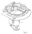
- a hopper 10 receives coins of mixed denominations and feeds them through central openings in an annular sorting head or guide plate 12. As the coins pass through these openings, they are deposited on the top surface of a rotatable disc 13. This disc 13 is mounted for rotation on a stub shaft (not shown) and driven by an electric motor 14.
- the disc 13 comprises a resilient pad 16, preferably made of a resilient rubber or polymeric material, bonded to the top surface of a solid metal disc 17.
- the outwardly moving coins initially enter an annular recess 20 formed in the underside of the guide plate 12 and extending around a major portion of the inner periphery of the annular guide plate.
- the outer wall 21 of the recess 20 extends downwardly to the lowermost surface 22 of the guide plate (see FIG. 3), which is spaced from the top surface of the pad 16 by a distance which is slightly less, e.g., 0,245 mm (0.010 inch), than the thickness of the thinnest coins. Consequently, the initial radial movement of the coins is terminated when they engage the wall 21 of the recess 20, though the coins continue to move circumferentially along the wall 21 by the rotational movement of the pad 16. Overlapping coins which only partially enter the recess 20 are stripped apart by a notch 20a formed in the top surface of the recess 20 along its inner edge (see FIG. 4).
- the only portion of the central opening of the guide plate 12 which does not open directly into the recess 20 is that sector of the periphery which is occupied by a land 23 whose lower surface is at the same elevation as the lowermost surface 22 of the guide plate.
- the upstream end of the land 23 forms a ramp 23a (FIG. 5), which prevents certain coins stacked on top of each other from reaching the ramp 24.
- the recess 25 is preferably just slightly wider than the diameter of the coin denomination having the greatest diameter.
- the top surface of the major portion of the recess 25 is spaced away from the top of the pad 16 by a distance that is less than the thickness of the thinnest coin so that the coins are gripped between the guide plate 12 and the resilient pad 16 as they are rotated through the recess 25.
- a narrow band 25a of the top surface of the recess 25 adjacent its inner wall 26 is spaced away from the pad 16 by approximately the thickness of the thinnest coin. This ensures that coins of all denominations (but only the upper coin in a stacked or shingled pair) are securely engaged by the wall 26 as it spirals outwardly.
- the rest of the top surface of the recess 25 tapers downwardly from the band 25a to the outer edge of the recess 25. This taper causes the coins to be tilted slightly as they move through the recess 25, as can be seen in FIGS. 6-8, thereby further ensuring continuous engagement of the coins with the outwardly spiraling wall 26.
- Rotation of the pad 16 continues to move the coins along the wall 26 until those coins engage a ramp 27 sloping downwardly from the recess 25 to a region 22a of the lowermost surface 22 of the guide plate 12 (see FIG. 9). Because the surface 22 is located even closer to the pad 16 than the recess, the effect of the ramp 27 is to further depress the coins into the resilient pad 16 as the coins are advanced along the ramp by the rotating disc. This causes the coins to be even more firmly gripped between the guide plate surface region 22a and the resilient pad 16, thereby securely holding the coins in a fixed radial position as they continue to be rotated along the underside of the guide plate by the rotating disc.
- this recess 30 forms an inwardly spiralling wall 31 which engages and precisely positions the outer edges of the coins before the coins reach the exit channels which serve as means for discriminating among coins of different denominations according to their different diameters.
- the inwardly spiralling wall 31 reduces the spacing between successive coins, but only to a minor extent so that successive coins remain spaced apart.
- the inward spiral closes any spaces between the wall 31 and the outer edges of the coins so that the outer edges of all the coins are eventually located at a common radial position, against the wall 31, regardless of where the outer edges of those coins were located when they initially entered the recess 30.
- a ramp 32 slopes downwardly from the top surface of the referencing recess 30 to region 22b of the lowermost surface 22 of the guide plate.
- the coins are gripped between the guide plate 12 and the resilient pad 16 with the maximum compressive force. This ensures that the coins are held securely in the radial position initially determined by the wall 31 of the referencing recess 30.
- the guide plate 12 forms a series of exit channels 40, 41, 42, 43, 44 and 45 which function as selecting means to discharge coins of different denominations at different circumferential locations around the periphery of the guide plate.
- the channels 40-45 are spaced circumferentially around the outer periphery of the plate 12, with the innermost edges of successive pairs of channels located progressively farther away from the common radial location of the outer edges of all coins for receiving and ejecting coins in order of increasing diameter.
- the six channels 40-45 are positioned and dimensioned to eject only dimes (channels 40 and 41), nickels (channels 42 and 43) and quarters (channel 44 and 45).
- the innermost edges of the exit channels 40-45 are positioned so that the inner edge of a coin of only one particular denomination can enter each channel; the coins of all other denominations reaching a given exit channel extend inwardly beyond the innermost edge of that particular channel so that those coins cannot enter the channel and, therefore, continue on to the next exit channel.
- the cross-sectional profile of the exit channels 40-45 is shown most clearly in FIG. 14, which is a section through the dime channel 40.
- the cross-sectional configurations of all the exit channels are similar; they vary only in their widths and their circumferential and radial positions.
- the width of the deepest portion of each exit channel is smaller than the diameter of the coin to be received and ejected by that particular exit channel, and the stepped surface of the guide plate adjacent the radially outer edge of each exit channel presses the outer portions of the coins received by that channel into the resilient pad so that the inner edges of those coins are tilted upwardly into the channel (see FIG. 14).
- the exit channels extend outwardly to the periphery of the guide plate so that the inner edges of the channels guide the tilted coins outwardly and eventually eject those coins from between the guide plate 12 and the resilient pad 16.
- each clamping-ring arrangement includes a support bracket 71 below which the corresponding coin guide tube 51 is supported in such a way that the inlet to the guide tube is aligned with the outlet of the corresponding guide channel.
- a clamping ring 72 having a diameter which is slightly larger than the diameter of the upper portions of the guide tubes 51 is slidably disposed on each guide tube. This permits a coin bag B to be releasably fastened to the guide tube 51 by positioning the mouth of the bag over the flared end of the tube and then sliding the clamping ring down until it fits tightly around the bag on the flared portion of the tube, as illustrated in FIG. 18.
- the clamping ring is preferably made of steel, and a plurality of magnets 73 are disposed on the underside of the support bracket 71 to hold the ring 72 in its released position while a full coin bag is being replaced with an empty bag.
- Each clamping-ring arrangement is also provided with a bag interlock switch for indicating the presence or absence of a coin bag at each bag station.
- a magnetic reed switch 74 of the "normally-closed" type is disposed beneath the bracket 71 of each clamping-ring arrangement.
- the switch 74 is adapted to be activated when the corresponding clamping ring 72 contacts the magnets 73 and thereby conducts the magnetic field generated by the magnets 73 into the vicinity of the switch 74. This normally occurs when a previously clamped full coin bag is released and has not yet been replaced with an empty coin bag.
- a similar mechanism is provided for each of the other bag stations BS.
- each coin denomination can be discharged at either of two different locations around the periphery of the guide plate 12, i.e., at the outer ends of the channels 40 and 41 for the dimes, at the outer ends of the channels 43 and 44 for the nickels, and at the outer ends of the channels 45 and 46 for the quarters.
- a controllably actuatable shunting device is associated with the first of each of the three pairs of similar exit channels 40-41, 42-43 and 44-45. When one of these shunting devices is actuated, it shunts coins of the corresponding denomination from the first to the second of the two exit channels provided for that particular denomination.
- a vertically movable bridge 80 is positioned adjacent the inner edge of the first channel 40, at the entry end of that channel.
- This bridge 80 is normally held in its raised, retracted position by means of a spring 81 (FIG. 14), as will be described in more detail below.
- a spring 81 FIG. 14
- a solenoid S D (FIGS. 14, 15 and 19) is energized to overcome the force of the spring 81 and lower the bridge 80 to its advanced position. In this lowered position, shown in FIG. 15, the bottom of the bridge 80 is flush with the lowermost surface 22b of the guide plate 12, which has the effect of preventing dimes D from entering the exit channel 40. Consequently, the quarters are rotated past the exit channel 40 by the rotating disc, sliding across the bridge 80, and enter the second exit channel 41.
- the bridge 80 To ensure that precisely the desired number of dimes are discharged through the exit channel 40, the bridge 80 must be interposed between the last dime for any prescribed batch and the next successive dime (which is normally the first dime for the next batch). To facilitate such interposition of the bridge 80 between two successive dimes, the dimension of the bridge 80 in the direction of coin movement is relatively short, and the bridge is located along the edges of the coins, where the space between successive coins is at a maximum.
- the fact that the exit channel 40 is narrower than the coins also helps ensure that the outer edge of a coin will not enter the exit channel while the bridge is being moved from its retracted position to its advanced position. In fact, with the illustrative design, the bridge 80 can be advanced after a dime has already partially entered the exit channel 40, overlapping all or part of the bridge, and the bridge will still shunt that dime to the next exit channel 41.
- the details of the actuating mechanism for the bridge 80 are illustrated in FIGS. 14 and 15.
- the bridges 90 and 100 have similar actuating mechanisms, and thus only the mechanism for the bridge 80 will be described.
- the bridge 80 is mounted on the lower end of a plunger 110 which slides vertically through a guide bushing 111 threaded into a hole bored into the guide plate 12.
- the bushing 111 is held in place by a locking nut 112.
- a smaller hole 113 is formed in the lower portion of the plate 12 adjacent the lower end of the bushing 111, to provide access for the bridge 80 into the exit channel 40.
- the bridge 80 is normally held in its retracted position by the coil spring 81 compressed between the locking nut 112 and a head 114 on the upper end of the plunger 110.
- the upward force of the spring 81 holds the bridge 80 against the lower end of the bushing 111.
- the solenoid coil is energized to push the plunger 110 downwardly with a force sufficient to overcome the upward force of the spring 81.
- the plunger is held in this advanced position as long as the solenoid coil remains energized, and is returned to its normally raised position by the spring 81 as soon as the solenoid is de-energized.
- Solenoids S N and S Q control the bridges 90 and 100 in the same manner described above in connection with the bridge 80 and the solenoid S D .
- each coin denomination is separately counted at a counting station along the lower surface of the guide plate, before the coins are sorted.
- the counted coins are then sorted at sorting stations spaced circumferentially from the counting station in the direction of coin movement.
- the present invention provides ample time for actuation of a movable control member for affecting the movement of one or more coin denominations at some point between the counting station and the coin-discharge locations. Movement of any given coin from its counting sensor to the point where its movement is affected by the control member can be monitored with a high degree of precision.
- movement of the control member can be timed to affect the coin movement, downstream of the counting sensors, to ensure that no coins following the last coin within any desired batch (defined by a prescribed count) are discharged at a selected bag station. Even the response time of the movable control member can be taken into account so that the control member actually moves to affect the coin movement at precisely the desired instant.
- the control members comprise the shunting bridges 80, 90 and 100, and the coins are counted as they move through the referencing recess 30.
- the outer edges of all coin denominations are at the same radial position at any given angular location along the edge. Consequently, the inner edges of coins of different denominations are offset from each other at any given angular location, due to the different diameters of the coins (see FIG. 2). These offset inner edges of the coins are used to separately count each coin before it leaves the referencing recess 30.
- three coin sensors S1, S2 and S3 in the form of insulated electrical contact pins are mounted in the upper surface of the recess 30.
- the outermost sensor S1 is positioned so that it is contacted by all three coin denominations
- the middle sensor S2 is positioned so that it is contacted only by the nickels and quarters
- the innermost sensor S3 is positioned so that it is contacted only by the quarters.
- An electrical voltage is applied to each sensor so that when a coin contacts the pin and bridges across its insulation, the voltage source is connected to ground via the coin and the metal head surrounding the insulated sensor.
- the grounding of the sensor during the time interval when it is contacted by the coin generates an electrical pulse which is detected by a counting system connected to the sensor.
- the pulses produced by coins contacting the three sensors S1, S2 and S3 will be referred to herein as pulses P1, P2 and P3, respectively, and the accumulated counts of those pulses in the counting system will be referred to as counts C1, C2 and C3, respectively.
- the output signal from the sensor can consist of a series of short pulses rather than a single wide pulse, which is a common problem referred to as "contact bounce.”
- This problem can be overcome by simply detecting the first pulse and then ignoring subsequent pulses during the time interval required for one coin to cross the sensor. Thus, only one pulse is detected for each coin that contacts the sensor.
- the outer sensor S1 contacts all three coin denominations, so the actual dime count C D is determined by subtracting C2 (the combined quarter and nickel count) from C1 (the combined count of quarters, nickels and dimes).
- the middle sensor S2 contacts both the quarters and the nickels, so the actual nickel count C N is determined by subtracting C3 (the quarter count) from C2 (the combined quarter and nickel count). Because the innermost sensor S3 contacts only quarters, the count C3 is the actual quarter count C Q .
- Another counting technique uses the combination of (1) the presence of a pulse P1 from the sensor S1 and (2) the absence of a pulse P2 from the sensor S2 to detect the presence of a dime.
- a nickel is detected by the combination of (1) the presence of a pulse P2 from the sensor S2 and (2) the absence of a pulse P3 from sensor S3, and a quarter is detected by the presence of a pulse P3 from the sensor S3.
- the presence or absence of the respective pulses can be detected by a simple logic routine which can be executed by either hardware or software.
- the two counters C3 and C'3 count the same pulses P3, but can be reset to zero at different times.
- the count C1 is reset to zero, which occurs each time the dime count C D reaches its limit C MAX . That is, the count C2 is needed to compute both the dime count C D and the nickel count C N , which are usually reset at different times.
- the pulses P2 are supplied to two different counters C2 ad C'2.
- the first counter C2 is reset to zero only when the nickel count C N reaches its C NMAX
- the second counter is reset to zero each time C1 is reset to zero when C D reaches its limit C DMAX .
- a control signal is generated to initiate a bag-switching or bag-stop function.
- the control signal is used to actuate the movable shunt within the first of the two exit channels provided for the appropriate coin denomination. This enables the coin sorter to operate continuously (assuming that each full coin bag is replaced with an empty bag before the second bag for that same denomination is filled) because there is no need to stop the sorter either to remove full bags or to remove excess coins from the bags.
- the control signal preferably stops the drive for the rotating disc and at the same time actuates a brake for the disc.
- the disc drive can be stopped either by de-energizing the drive motor or by actuating a clutch which de-couples the drive motor from the disc.
- An alternative bag-stop system uses a movable diverter within a coin-recycling slot located between the counting sensors and the exit channels. Such a recycling diverter is described, for example, in U.S. Patent No. 4,564,036 issued January 14, 1986, for "Coin Sorting System With Controllable Stop.”
- FIG. 19 there is shown an upper level block diagram of an illustrative microprocessor-based control system 200 for controlling the operation of a coin sorter incorporating the counting and sorting system of this invention.
- the control system 200 includes a central processor unit (CPU) 201 for monitoring and regulating the various parameters involved in the coin sorting/counting and bag-stopping and switching operations.
- CPU central processor unit
- the CPU 201 accepts signals from (1) the bag-interlock switches 74 which provide indications of the positions of the bagclamping rings 72 which are used to secure coin bags B to the six coin guide tubes 51, to indicate whether or not a bag is available to receive each coin denomination, (2) the three coin sensors S1-S3, (3) an encoder sensor E5 and (4) three coin-tracking counters CTC D , CTC N and CTC Q .
- the CPU 201 produces output signals to control the three shunt solenoids S D , S N and S Q , the main drive motor M1, an auxiliary drive motor M2, a brake B and the three coin-tracking counters.
- FIG. 16 A drive system for the rotating disc, for use in conjunction with the control system of FIG. 19, is illustrated in FIG. 16.
- the disc is normally driven by a main a-c. drive motor M1 which is coupled directly to the coin-carrying disc 13 through a speed reducer 210.
- a brake B is actuated at the same time the main motor M1 is de-energized.
- the outer peripheral surface of the disc carries an encoder in the form of a large number of uniformly spaced indicia 211 (either optical or magnetic) which can be sensed by an encoder sensor 212.
- the disc has 720 indicia 211 so that the sensor 212 produces an output pulse for every 0.5° of movement of the disc 13.
- the pulses from the encoder sensor 212 are supplied to the three coin-tracking down counters CTD D , CTC N and CTC Q for separately monitoring the movement of each of the three coin denominations between fixed points on the sorting head.
- the outputs of these three counters CTC D , CTC N and CTC Q can then be used to separately control the actuation of the bag-switching bridges 80, 90 and 100 and/or the drive system.
- the dimetracking counter CTC D is preset to count the movement of a predetermined number of the indicia 211 on the disc periphery past the encoder sensor 212. This is a way of measuring the movement of the last dime through an angular displacement that brings that last dime to a position where the bag-switching bridge 80 should be actuated to interpose the bridge between the last dime and the next successive dime.
- a dime In the sorting head of FIG. 2, a dime must traverse an angle of 20° to move from the position where it has just cleared the last counting sensor S1 to the position where it has just cleared the bag-switching bridge 80. At a disc speed of 250 rpm, the disc turns -- and the coin moves -- at a rate of 1.5° per millisecond. A typical response time for the solenoid that moves the bridge 80 is 6 milliseconds (4 degrees of disc movement), so the control signal to actuate the solenoid should be transmitted when the last dime is 4 degrees from its bridge-clearing position. In the case where the encoder has 720 indicia around the circumference of the disc, the encoder sensor produces a pulse for ever 0.5° of disc movement.
- the coin-tracking counter CTC D for the dime is preset to 32 when the last dime is sensed, so that the counter CTC D counts down to zero, and generates the required control signal, when the dime has advanced 16° beyond the last sensor S1. This ensures that the bridge 80 will be moved just after it has been cleared by the last dime, so that the bridge 80 will be interposed between that last dime and the next successive dime.
- control means may be provided for reducing the speed of the rotating disc 13 as the last coin in a prescribed batch is approaching the bridge. Reducing the speed of the rotating disc in this brief time interval has little effect on the overall throughput of the system, and yet it significantly increases the time interval available between the instant when the trailing edge of the last coin clears the bridge and the instant when the leading edge of the next successive coin reaches the bridge. Consequently, the timing of the interposing movement of the bridge relative to the coin flow past the bridge becomes less critical and, therefore, it becomes easier to implement and more reliable in operation.
- Reducing the speed of the rotating disc is preferably accomplished by reducing the speed of the motor which drives the disc.
- this speed reduction can be achieved by actuation of a brake for the rotating disc, or by a combination of brake actuation and speed reduction of the drive motor.
- FIG. 16 One example of a drive system for controllably reducing the speed of the disc 13 is illustrated in FIG. 16.
- This system includes an auxiliary d-c. motor M2 connected to the drive shaft of the main drive motor M1 through a timing belt 213 and an overrun clutch 214.
- the speed of the auxiliary motor M2 is controlled by a drive control circuit 215 through a current sensor 216 which continuously monitors the armature current supplied to the auxiliary motor M2.
- the auxiliary d-c. motor M2 can be quickly accelerated to its normal speed while the main motor M1 is decelerating.
- the output shaft of the auxiliary motor turns a gear which is connected to a larger gear through the timing belt 213, thereby forming a speed reducer for the output of the auxiliary motor M2.
- the overrun clutch 214 is engaged only when the auxiliary motor M2 is energized, and serves to prevent the rotational speed of the disc 13 from decreasing below a predetermined level while the disc is being driven by the auxiliary motor.
- the controller 201 when the prescribed number of coins of a prescribed denomination has been counted for a given coin batch, the controller 201 produces control signals which energize the brake B and the auxiliary motor M2 and de-energize the main motor M1.
- the auxiliary motor M2 rapidly accelerates to its normal speed, while the main motor M1 decelerates.
- the brake overrides the output of the auxiliary motor, thereby causing the armature current of the auxiliary motor to increase rapidly.
- this armature current exceeds a preset level, it initiates de-actuation of the brake, which is then disengaged after a short time delay.
- the armature current of the auxiliary motor drops rapidly to a normal level needed to sustain the normal speed of the auxiliary motor.
- the disc then continues to be driven by the auxiliary motor alone, at a reduced rotational speed, until the encoder sensor 212 indicates that the last coin in the batch has passed the position where that coin has cleared the bag-switching bridge in the first exit slot for that particular denomination.
- the main drive rotor is re-energized, and the auxiliary motor is de-energized.
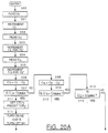
- FIG. 20 there is shown a flow chart 220 illustrating the sequence of operations involved in utilizing the bag-switching system of the illustrative sorter of FIG. 1 in conjunction with the microprocessor-based system discussed above with respect to FIG. 19.
- the subroutine illustrated in FIG. 20 is executed multiple times in every millisecond. Any given coin moves past the coin sensors at a rate of about 1.5° per millisecond. Thus, several milliseconds are required for each coin to traverse the sensors, and so the subroutine of FIG. 20 is executed several times during the sensor-traversing movement of each coin.
- the first six steps 300-305 in the subroutine of FIG. 20 determine whether the interrupt controller has received any pulses from the three sensors S1-S3. If the answer is affirmative for any of the three sensors, the corresponding count C1, C2, C'2, C3 and C'3 is incremented by one. Then at step 306 the actual dime count C D is computed by subtracting count C'2 from C1. The resulting value C D is then compared with the current selected limit value C DMAX at step 307 to determine whether the selected number of dimes has passed the sensors. If the answer is negative, the subroutine advances to step 308 where the actual nickel count C N is computed by subtracting count C'3 from C2.
- the resulting value C N is then compared with the selected nickel limit value C NMAX at step 309 to determine whether the selected number of nickels has passed the sensors.
- step 311 An affirmative answer at step 311 indicates that the selected number of dimes has been counted, and thus the bridge 80 in the first exit slot 40 for the dime must be actuated so that it diverts all dimes following the last dime in the completed batch.
- step 311 presets the coin-tracking counter CTC D to a value P D .
- the counter CTC D then counts down from P D in response to successive pulses from the encoder sensor ES as the last dime is moved from the last sensor S3 toward the bridge 80.
- step 314 turns off the main drive motor M1 and turns on the auxiliary d-c. drive motor M2 and the brake B. This initiates the sequence of operations described above, in which the brake B is engaged while the main drive motor M1 is decelerating and then disengaged while the auxiliary motor M2 drives the disc 13 so that the last dime is moving at a controlled constant speed as it approaches and passes the bridge 80.
- step 315 of the subroutine determines whether the solenoid S D is already energized. An affirmative response at step 315 indicates that it is bag B that contains the preset number of coins, and thus the system proceeds to step 316 to determine whether bag A is available. If the answer is negative, indicating that bag A is not available, then there is no bag available for receiving dimes and the sorter must be stopped. Accordingly, the system proceeds to step 317 where the auxiliary motor M2 is turned off and the brake B is turned on to stop the disc 13 after the last dime is discharged into bag B. The sorter cannot be re-started again until the bag-interlock switches for the dime bags indicate that the full bag has been removed and replaced with an empty bag.
- step 316 An affirmative answer at step 316 indicates that bag A is available, and thus the system proceeds to step 318 to determine whether the coin-tracking counter CTC D has reached zero, i.e., whether the OVFL D signal is on. The system reiterates this query until OVFL D is on, and then advances to step 319 to generate a control signal to de-energize the solenoid S D so that the bridge 80 is moved to its retracted (upper) position. This causes all the dimes for the next coin batch to enter the first exit channel 40 so that they are discharged into bag A.
- a negative answer at step 315 indicates the full bag is bag A rather than bag B, and thus the system proceeds to step 320 to determine whether bag B is available. If the answer is negative, it means that neither bag A nor bag B is available to receive the dimes, and thus the sorter is stopped by advancing to step 317.
- An affirmative answer at step 320 indicates that bag B is, in fact, available, and thus the system proceeds to step 321 to determine when the solenoid S D is to be energized, in the same manner described above for step 318. Energizing the solenoid S D causes the bridge 80 to be advanced to its lower position so that all the dimes for the next batch are shunted past the first exit channel 40 to the second exit channel 41.
- the control signal for energizing the solenoid is generated at step 321 when step 320 detects that OVFL D is on.
- the subroutine resets the counters C1 and C'2 at step 323, and turns off the auxiliary motor M2 and the brake B and turns on the main drive motor M1 at step 324. This initializes the dime-counting portion of the system to begin the counting of a new batch of dimes.
Abstract
Description
- The present invention relates generally to coin sorting and counting methods and, more particularly, to coin sorting and counting methods of the type which use a resilient disc rotating beneath a stationary sorting head for sorting coins of mixed denominations.
- EP-A-0314463 discloses a coin sorter in which coins of different denominations are counted after being discharged from the sorter. When a preselected number of coins have been counted, the brake mechanism is activated to stop the rotating disk.
- US-A-4681128 discloses a coin sorter, in which the sorting and counting is effected by pins.
- The present invention concerns a method of counting and sorting coins of mixed denominations in a disc-type coin sorter having a rotatable disc with a resilient surface for receiving said coins and imparting rotational movement to said coins, and a stationary sorting head having a contoured surface spaced slightly away from and generally parallel to said resilient surface of said rotatable disc , whereby said disc is rotated beneath said sorting head while feeding coins between said disk and sorting head, said method characterized by the following steps:
- Counting each coin denomination separately at a counting station along the lower surface of said sorting head;
- Sorting the counted coins at sorting stations spaced circumferentially from said counting station;
- Discharging the sorted coins at different exit stations around the periphery of said sorting head ; and
- Monitoring the angular movement of said disc after a prescribed number of coins has been counted, to determine when the last coin in said count has been moved to a predetermined location spaced circumferentially from said counting station in the direction of a coin movement.
-
- FIG. 1 is perspective view of a coin counting and sorting system for carrying out the method of the present invention, with portions thereof broken away to show the internal structure;
- FIG. 2 is an enlarged horizontal section taken generally along the line 2-2 in FIG. 1 to show the configuration of the underside of the sorting head or guide plate;
- FIG. 3 is an enlarged section taken generally along line 3-3 in FIG. 2;
- FIG. 4 is an enlarged section taken generally along line 4-4 in FIG. 2;
- FIG. 5 is an enlarged section taken generally along line 5-5 in FIG. 2;
- FIG. 6 is an enlarged section taken generally along line 6-6 in FIG. 2;
- FIG. 7 is an enlarged section taken generally along line 7-7 in FIG. 2;
- FIG. 8 is an enlarged section taken generally along line 8-8 in FIG. 2;
- FIG. 9 is an enlarged section taken generally along line 9-9 in FIG. 2;
- FIG. 10 is an enlarged section taken generally along line 10-10 in FIG. 2;
- FIG. 11 is an enlarged section taken generally along line 11-11 in FIG. 2;
- FIG. 12 is an enlarged section taken generally along line 12-12 in FIG. 2;
- FIG. 13 is an enlarged section taken generally along line 13-13 in FIG. 2;
- FIG. 14 is an enlarged section taken generally along line 14-14 in FIG. 2, and illustrating a coin in the exit channel with the movable element in that channel in its retracted position;
- FIG. 15 is the same section shown in FIG. 14 with the movable element in its advanced position;
- FIG. 16 is an enlarged perspective view of a preferred drive system for the rotatable disc in the system of FIG. 1;
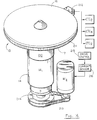
- FIG. 17 is a perspective view of a portion of the coin sorter of FIG. 1, showing two of the six coin discharge and bagging stations and certain of the components included in those stations;
- FIG. 18 is an enlarged section taken generally along line 18-18 in FIG. 17 and showing additional details of one of the coin discharge and bagging station;
- FIG. 19 is a block diagram of a microprocessor-based control system for use in the coin counting and sorting system of FIGS. 1-18;
- FIGS. 20A and 20B, combined, form a flow chart of a portion of a program for controlling the operation of the microprocessor included in the control system of FIG. 19;
- Turning now to the drawings and referring first to FIG. 1, a
hopper 10 receives coins of mixed denominations and feeds them through central openings in an annular sorting head orguide plate 12. As the coins pass through these openings, they are deposited on the top surface of arotatable disc 13. Thisdisc 13 is mounted for rotation on a stub shaft (not shown) and driven by anelectric motor 14. Thedisc 13 comprises aresilient pad 16, preferably made of a resilient rubber or polymeric material, bonded to the top surface of asolid metal disc 17. - As the
disc 13 is rotated, the coins deposited on the top surface thereof tend to slide outwardly over the surface of the pad due to centrifugal force. As the coins move outwardly, those coins which are lying flat on the pad enter the gap between the pad surface and theguide plate 12 because the underside of the inner periphery of this plate is spaced above thepad 16 by a distance which is about the same as the thickness of the thickest coin. - As can be seen most clearly in FIG. 2, the outwardly moving coins initially enter an
annular recess 20 formed in the underside of theguide plate 12 and extending around a major portion of the inner periphery of the annular guide plate. Theouter wall 21 of therecess 20 extends downwardly to thelowermost surface 22 of the guide plate (see FIG. 3), which is spaced from the top surface of thepad 16 by a distance which is slightly less, e.g., 0,245 mm (0.010 inch), than the thickness of the thinnest coins. Consequently, the initial radial movement of the coins is terminated when they engage thewall 21 of therecess 20, though the coins continue to move circumferentially along thewall 21 by the rotational movement of thepad 16. Overlapping coins which only partially enter therecess 20 are stripped apart by anotch 20a formed in the top surface of therecess 20 along its inner edge (see FIG. 4). - The only portion of the central opening of the
guide plate 12 which does not open directly into therecess 20 is that sector of the periphery which is occupied by aland 23 whose lower surface is at the same elevation as thelowermost surface 22 of the guide plate. The upstream end of theland 23 forms aramp 23a (FIG. 5), which prevents certain coins stacked on top of each other from reaching theramp 24. - As coins within the
recess 20 approach theland 23, those coins move outwardly around theland 23 and engage aramp 24 leading into arecess 25 which is an outward extension of the innerperipheral recess 20. Therecess 25 is preferably just slightly wider than the diameter of the coin denomination having the greatest diameter. The top surface of the major portion of therecess 25 is spaced away from the top of thepad 16 by a distance that is less than the thickness of the thinnest coin so that the coins are gripped between theguide plate 12 and theresilient pad 16 as they are rotated through therecess 25. Thus, coins which move into therecess 25 are all rotated into engagement with the outwardly spirallinginner wall 26, and then continue to move outwardly through therecess 25 with the inner edges of all the coins riding along thespiral wall 26. - As can be seen in FIGS. 6-8, a
narrow band 25a of the top surface of therecess 25 adjacent itsinner wall 26 is spaced away from thepad 16 by approximately the thickness of the thinnest coin. This ensures that coins of all denominations (but only the upper coin in a stacked or shingled pair) are securely engaged by thewall 26 as it spirals outwardly. The rest of the top surface of therecess 25 tapers downwardly from theband 25a to the outer edge of therecess 25. This taper causes the coins to be tilted slightly as they move through therecess 25, as can be seen in FIGS. 6-8, thereby further ensuring continuous engagement of the coins with the outwardlyspiraling wall 26. - Rotation of the
pad 16 continues to move the coins along thewall 26 until those coins engage aramp 27 sloping downwardly from therecess 25 to aregion 22a of thelowermost surface 22 of the guide plate 12 (see FIG. 9). Because thesurface 22 is located even closer to thepad 16 than the recess, the effect of theramp 27 is to further depress the coins into theresilient pad 16 as the coins are advanced along the ramp by the rotating disc. This causes the coins to be even more firmly gripped between the guideplate surface region 22a and theresilient pad 16, thereby securely holding the coins in a fixed radial position as they continue to be rotated along the underside of the guide plate by the rotating disc. - As the coins emerge from the
ramp 27, the coins enter a referencing and countingrecess 30 which still presses all coin denominations firmly against theresilient pad 16. The outer edge of thisrecess 30 forms an inwardlyspiralling wall 31 which engages and precisely positions the outer edges of the coins before the coins reach the exit channels which serve as means for discriminating among coins of different denominations according to their different diameters. - The inwardly
spiralling wall 31 reduces the spacing between successive coins, but only to a minor extent so that successive coins remain spaced apart. The inward spiral closes any spaces between thewall 31 and the outer edges of the coins so that the outer edges of all the coins are eventually located at a common radial position, against thewall 31, regardless of where the outer edges of those coins were located when they initially entered therecess 30. - At the downstream end of the referencing recess 30, a ramp 32 (FIG. 13) slopes downwardly from the top surface of the referencing recess 30 to
region 22b of thelowermost surface 22 of the guide plate. Thus, at the downstream end of theramp 32 the coins are gripped between theguide plate 12 and theresilient pad 16 with the maximum compressive force. This ensures that the coins are held securely in the radial position initially determined by thewall 31 of the referencing recess 30. - Beyond the referencing recess 30, the
guide plate 12 forms a series ofexit channels plate 12, with the innermost edges of successive pairs of channels located progressively farther away from the common radial location of the outer edges of all coins for receiving and ejecting coins in order of increasing diameter. In the particular embodiment illustrated, the six channels 40-45 are positioned and dimensioned to eject only dimes (channels 40 and 41), nickels (channels 42 and 43) and quarters (channel 44 and 45). The innermost edges of the exit channels 40-45 are positioned so that the inner edge of a coin of only one particular denomination can enter each channel; the coins of all other denominations reaching a given exit channel extend inwardly beyond the innermost edge of that particular channel so that those coins cannot enter the channel and, therefore, continue on to the next exit channel. - The cross-sectional profile of the exit channels 40-45 is shown most clearly in FIG. 14, which is a section through the
dime channel 40. Of course, the cross-sectional configurations of all the exit channels are similar; they vary only in their widths and their circumferential and radial positions. The width of the deepest portion of each exit channel is smaller than the diameter of the coin to be received and ejected by that particular exit channel, and the stepped surface of the guide plate adjacent the radially outer edge of each exit channel presses the outer portions of the coins received by that channel into the resilient pad so that the inner edges of those coins are tilted upwardly into the channel (see FIG. 14). The exit channels extend outwardly to the periphery of the guide plate so that the inner edges of the channels guide the tilted coins outwardly and eventually eject those coins from between theguide plate 12 and theresilient pad 16. - As coins are discharged from the six exit channels 40-45, the coins are guided down toward six corresponding bag stations BS by six
arcuate guide channels 50, as shown in FIGS. 17 and 18. Only two of the six bag stations BS are illustrated in FIG. 17, and one of the stations is illustrated in FIG. 18. - As the coins leave the lower ends of the
guide channels 50, they enter correspondingcylindrical guide tubes 51 which are part of the bag stations BS. The lower ends of thesetubes 51 flare outwardly to accommodate conventional clamping-ring arrangements for mounting coin bags B directly beneath thetubes 51 to receive coins therefrom. - As can be seen in FIG. 18, each clamping-ring arrangement includes a
support bracket 71 below which the correspondingcoin guide tube 51 is supported in such a way that the inlet to the guide tube is aligned with the outlet of the corresponding guide channel. A clampingring 72 having a diameter which is slightly larger than the diameter of the upper portions of theguide tubes 51 is slidably disposed on each guide tube. This permits a coin bag B to be releasably fastened to theguide tube 51 by positioning the mouth of the bag over the flared end of the tube and then sliding the clamping ring down until it fits tightly around the bag on the flared portion of the tube, as illustrated in FIG. 18. Releasing the coin bag merely requires the clamping ring to be pushed upwardly onto the cylindrical section of the guide tube. The clamping ring is preferably made of steel, and a plurality ofmagnets 73 are disposed on the underside of thesupport bracket 71 to hold thering 72 in its released position while a full coin bag is being replaced with an empty bag. - Each clamping-ring arrangement is also provided with a bag interlock switch for indicating the presence or absence of a coin bag at each bag station. In the illustrative embodiment, a
magnetic reed switch 74 of the "normally-closed" type is disposed beneath thebracket 71 of each clamping-ring arrangement. Theswitch 74 is adapted to be activated when thecorresponding clamping ring 72 contacts themagnets 73 and thereby conducts the magnetic field generated by themagnets 73 into the vicinity of theswitch 74. This normally occurs when a previously clamped full coin bag is released and has not yet been replaced with an empty coin bag. A similar mechanism is provided for each of the other bag stations BS. - As described above, two different exit channels are provided for each coin denomination. Consequently, each coin denomination can be discharged at either of two different locations around the periphery of the
guide plate 12, i.e., at the outer ends of thechannels channels channels 45 and 46 for the quarters. In order to select one of the two exit channels available for each denomination, a controllably actuatable shunting device is associated with the first of each of the three pairs of similar exit channels 40-41, 42-43 and 44-45. When one of these shunting devices is actuated, it shunts coins of the corresponding denomination from the first to the second of the two exit channels provided for that particular denomination. - Turning first to the pair of
exit channels movable bridge 80 is positioned adjacent the inner edge of thefirst channel 40, at the entry end of that channel. Thisbridge 80 is normally held in its raised, retracted position by means of a spring 81 (FIG. 14), as will be described in more detail below. When thebridge 80 is in this raised position, the bottom of the bridge is flush with the top wall of thechannel 40, as shown in FIG. 14, so that dimes D enter thechannel 40 and are discharged through that channel in the normal manner. - When it is desired to shunt dimes past the
first exit channel 40 to thesecond exit channel 41, a solenoid SD (FIGS. 14, 15 and 19) is energized to overcome the force of thespring 81 and lower thebridge 80 to its advanced position. In this lowered position, shown in FIG. 15, the bottom of thebridge 80 is flush with thelowermost surface 22b of theguide plate 12, which has the effect of preventing dimes D from entering theexit channel 40. Consequently, the quarters are rotated past theexit channel 40 by the rotating disc, sliding across thebridge 80, and enter thesecond exit channel 41. - To ensure that precisely the desired number of dimes are discharged through the
exit channel 40, thebridge 80 must be interposed between the last dime for any prescribed batch and the next successive dime (which is normally the first dime for the next batch). To facilitate such interposition of thebridge 80 between two successive dimes, the dimension of thebridge 80 in the direction of coin movement is relatively short, and the bridge is located along the edges of the coins, where the space between successive coins is at a maximum. The fact that theexit channel 40 is narrower than the coins also helps ensure that the outer edge of a coin will not enter the exit channel while the bridge is being moved from its retracted position to its advanced position. In fact, with the illustrative design, thebridge 80 can be advanced after a dime has already partially entered theexit channel 40, overlapping all or part of the bridge, and the bridge will still shunt that dime to thenext exit channel 41. - Vertically
movable bridges 90 and 100 (FIG. 2) located in thefirst exit channels bridge 80. Thus, thenickel bridge 90 is located along the inner edge of the firstnickel exit channel 42, at the entry end of that exit channel. Thebridge 90 is normally held in its raised, retracted position by means of a spring. In this raised position the bottom of thebridge 90 is flush with the top wall of theexit channel 42, so that nickels enter thechannel 42 and are discharged through that channel. When it is desired to divert nickels to thesecond exit channel 43, a solenoid SN (FIG. 19) is energized to overcome the force of the spring and lower thebridge 90 to its advanced position, where the bottom of the bridge 60 is flush with thelowermost surface 22b of theguide plate 12. When thebridge 90 is in this advanced position, the bridge prevents any coins from entering thefirst exit channel 42. Consequently, the nickels slide across thebridge 90, continue on to thesecond exit channel 43 and are discharged therethrough. The quarter bridge 100 (FIG. 2) and its solenoid SQ (FIG. 19) operate in exactly the same manner. The edges of all thebridges - The details of the actuating mechanism for the
bridge 80 are illustrated in FIGS. 14 and 15. Thebridges bridge 80 will be described. Thebridge 80 is mounted on the lower end of aplunger 110 which slides vertically through a guide bushing 111 threaded into a hole bored into theguide plate 12. The bushing 111 is held in place by a lockingnut 112. Asmaller hole 113 is formed in the lower portion of theplate 12 adjacent the lower end of the bushing 111, to provide access for thebridge 80 into theexit channel 40. Thebridge 80 is normally held in its retracted position by thecoil spring 81 compressed between the lockingnut 112 and ahead 114 on the upper end of theplunger 110. The upward force of thespring 81 holds thebridge 80 against the lower end of the bushing 111. - To advance the
plunger 110 to its lowered position within the exit channel 40 (FIG. 15), the solenoid coil is energized to push theplunger 110 downwardly with a force sufficient to overcome the upward force of thespring 81. The plunger is held in this advanced position as long as the solenoid coil remains energized, and is returned to its normally raised position by thespring 81 as soon as the solenoid is de-energized. - Solenoids SN and SQ control the
bridges bridge 80 and the solenoid SD. - In accordance with one aspect of the present invention, each coin denomination is separately counted at a counting station along the lower surface of the guide plate, before the coins are sorted. The counted coins are then sorted at sorting stations spaced circumferentially from the counting station in the direction of coin movement. By counting the various coin denominations prior to sorting, the present invention provides ample time for actuation of a movable control member for affecting the movement of one or more coin denominations at some point between the counting station and the coin-discharge locations. Movement of any given coin from its counting sensor to the point where its movement is affected by the control member can be monitored with a high degree of precision. Thus, movement of the control member can be timed to affect the coin movement, downstream of the counting sensors, to ensure that no coins following the last coin within any desired batch (defined by a prescribed count) are discharged at a selected bag station. Even the response time of the movable control member can be taken into account so that the control member actually moves to affect the coin movement at precisely the desired instant.
- In the particular embodiment of the invention illustrated in FIGS. 2-15, the control members comprise the shunting bridges 80, 90 and 100, and the coins are counted as they move through the referencing
recess 30. As the coins move along thewall 31 of the recess, the outer edges of all coin denominations are at the same radial position at any given angular location along the edge. Consequently, the inner edges of coins of different denominations are offset from each other at any given angular location, due to the different diameters of the coins (see FIG. 2). These offset inner edges of the coins are used to separately count each coin before it leaves the referencingrecess 30. - As can be seen in FIGS.2 and 10-12, three coin sensors S₁, S₂ and S₃ in the form of insulated electrical contact pins are mounted in the upper surface of the
recess 30. The outermost sensor S₁ is positioned so that it is contacted by all three coin denominations, the middle sensor S₂ is positioned so that it is contacted only by the nickels and quarters, and the innermost sensor S₃ is positioned so that it is contacted only by the quarters. An electrical voltage is applied to each sensor so that when a coin contacts the pin and bridges across its insulation, the voltage source is connected to ground via the coin and the metal head surrounding the insulated sensor. The grounding of the sensor during the time interval when it is contacted by the coin generates an electrical pulse which is detected by a counting system connected to the sensor. The pulses produced by coins contacting the three sensors S₁, S₂ and S₃ will be referred to herein as pulses P₁, P₂ and P₃, respectively, and the accumulated counts of those pulses in the counting system will be referred to as counts C₁, C₂ and C₃, respectively. - As a coin traverses one of the sensors, intermittent contact can occur between the coin and the sensor because of the contour of the coin surface. Consequently, the output signal from the sensor can consist of a series of short pulses rather than a single wide pulse, which is a common problem referred to as "contact bounce." This problem can be overcome by simply detecting the first pulse and then ignoring subsequent pulses during the time interval required for one coin to cross the sensor. Thus, only one pulse is detected for each coin that contacts the sensor.
- The outer sensor S₁ contacts all three coin denominations, so the actual dime count CD is determined by subtracting C₂ (the combined quarter and nickel count) from C₁ (the combined count of quarters, nickels and dimes). The middle sensor S₂, contacts both the quarters and the nickels, so the actual nickel count CN is determined by subtracting C₃ (the quarter count) from C₂ (the combined quarter and nickel count). Because the innermost sensor S₃ contacts only quarters, the count C₃ is the actual quarter count CQ.
- Another counting technique uses the combination of (1) the presence of a pulse P₁ from the sensor S₁ and (2) the absence of a pulse P₂ from the sensor S₂ to detect the presence of a dime. A nickel is detected by the combination of (1) the presence of a pulse P₂ from the sensor S₂ and (2) the absence of a pulse P₃ from sensor S₃, and a quarter is detected by the presence of a pulse P₃ from the sensor S₃. The presence or absence of the respective pulses can be detected by a simple logic routine which can be executed by either hardware or software.
- To permit the simultaneous counting of prescribed batches of coins of each denomination using the first counting technique described above, i.e., the subtraction algorithm, counts C₂ and C₃ must be simultaneously accumulated over two different time periods. For example, count C₃ is the actual quarter count CQ, which normally has its own operator-selected limit CQMAX. While the quarter count CQ (= C₃) is accumulating toward its own limit CQMAX, however, the nickel count CN (= C₂ - C₃) might reach its limit CNMAX and be reset to zero to start the counting of another batch of nickels. For accurate computation of CN following its reset to zero, the count C₃ must also be reset at the same time. The count C₃, however, is still needed for the ongoing count of quarters; thus the pulses P₃ are supplied to a second counter C'₃ which counts the same pulses P₃ that are counted by the first counter C₃ but is reset each time the counter C₂ is reset. Thus, the two counters C₃ and C'₃ count the same pulses P₃, but can be reset to zero at different times.
- The same problem addressed above also exists when the count C₁ is reset to zero, which occurs each time the dime count CD reaches its limit CMAX. That is, the count C₂ is needed to compute both the dime count CD and the nickel count CN, which are usually reset at different times. Thus, the pulses P₂ are supplied to two different counters C₂ ad C'₂. The first counter C₂ is reset to zero only when the nickel count CN reaches its CNMAX, and the second counter is reset to zero each time C₁ is reset to zero when CD reaches its limit CDMAX.
- Whenever one of the counts CD, CN or CQ reaches its limit, a control signal is generated to initiate a bag-switching or bag-stop function.
- For the bag-switching function, the control signal is used to actuate the movable shunt within the first of the two exit channels provided for the appropriate coin denomination. This enables the coin sorter to operate continuously (assuming that each full coin bag is replaced with an empty bag before the second bag for that same denomination is filled) because there is no need to stop the sorter either to remove full bags or to remove excess coins from the bags.
- For a bag-stop function, the control signal preferably stops the drive for the rotating disc and at the same time actuates a brake for the disc. The disc drive can be stopped either by de-energizing the drive motor or by actuating a clutch which de-couples the drive motor from the disc. An alternative bag-stop system uses a movable diverter within a coin-recycling slot located between the counting sensors and the exit channels. Such a recycling diverter is described, for example, in U.S. Patent No. 4,564,036 issued January 14, 1986, for "Coin Sorting System With Controllable Stop."
- Referring now to FIG. 19, there is shown an upper level block diagram of an illustrative microprocessor-based
control system 200 for controlling the operation of a coin sorter incorporating the counting and sorting system of this invention. Thecontrol system 200 includes a central processor unit (CPU) 201 for monitoring and regulating the various parameters involved in the coin sorting/counting and bag-stopping and switching operations. TheCPU 201 accepts signals from (1) the bag-interlock switches 74 which provide indications of the positions of the bagclamping rings 72 which are used to secure coin bags B to the sixcoin guide tubes 51, to indicate whether or not a bag is available to receive each coin denomination, (2) the three coin sensors S₁-S₃, (3) an encoder sensor E₅ and (4) three coin-tracking counters CTCD, CTCN and CTCQ. TheCPU 201 produces output signals to control the three shunt solenoids SD, SN and SQ, the main drive motor M₁, an auxiliary drive motor M₂, a brake B and the three coin-tracking counters. - A drive system for the rotating disc, for use in conjunction with the control system of FIG. 19, is illustrated in FIG. 16. The disc is normally driven by a main a-c. drive motor M₁ which is coupled directly to the coin-carrying
disc 13 through aspeed reducer 210. To stop thedisc 13, a brake B is actuated at the same time the main motor M₁ is de-energized. To permit precise monitoring of the angular movement of thedisc 13, the outer peripheral surface of the disc carries an encoder in the form of a large number of uniformly spaced indicia 211 (either optical or magnetic) which can be sensed by anencoder sensor 212. In the particular example illustrated, the disc has 720indicia 211 so that thesensor 212 produces an output pulse for every 0.5° of movement of thedisc 13. - The pulses from the
encoder sensor 212 are supplied to the three coin-tracking down counters CTDD, CTCN and CTCQ for separately monitoring the movement of each of the three coin denominations between fixed points on the sorting head. The outputs of these three counters CTCD, CTCN and CTCQ can then be used to separately control the actuation of the bag-switchingbridges indicia 211 on the disc periphery past theencoder sensor 212. This is a way of measuring the movement of the last dime through an angular displacement that brings that last dime to a position where the bag-switchingbridge 80 should be actuated to interpose the bridge between the last dime and the next successive dime. - In the sorting head of FIG. 2, a dime must traverse an angle of 20° to move from the position where it has just cleared the last counting sensor S₁ to the position where it has just cleared the bag-switching
bridge 80. At a disc speed of 250 rpm, the disc turns -- and the coin moves -- at a rate of 1.5° per millisecond. A typical response time for the solenoid that moves thebridge 80 is 6 milliseconds (4 degrees of disc movement), so the control signal to actuate the solenoid should be transmitted when the last dime is 4 degrees from its bridge-clearing position. In the case where the encoder has 720 indicia around the circumference of the disc, the encoder sensor produces a pulse for ever 0.5° of disc movement. Thus the coin-tracking counter CTCD for the dime is preset to 32 when the last dime is sensed, so that the counter CTCD counts down to zero, and generates the required control signal, when the dime has advanced 16° beyond the last sensor S₁. This ensures that thebridge 80 will be moved just after it has been cleared by the last dime, so that thebridge 80 will be interposed between that last dime and the next successive dime. - In order to expand the time interval available for any of the bag-switching bridges to be interposed between the last coin in a prescribed batch and the next successive coin of that same denomination, control means may be provided for reducing the speed of the
rotating disc 13 as the last coin in a prescribed batch is approaching the bridge. Reducing the speed of the rotating disc in this brief time interval has little effect on the overall throughput of the system, and yet it significantly increases the time interval available between the instant when the trailing edge of the last coin clears the bridge and the instant when the leading edge of the next successive coin reaches the bridge. Consequently, the timing of the interposing movement of the bridge relative to the coin flow past the bridge becomes less critical and, therefore, it becomes easier to implement and more reliable in operation. - Reducing the speed of the rotating disc is preferably accomplished by reducing the speed of the motor which drives the disc. Alternatively, this speed reduction can be achieved by actuation of a brake for the rotating disc, or by a combination of brake actuation and speed reduction of the drive motor.
- One example of a drive system for controllably reducing the speed of the
disc 13 is illustrated in FIG. 16. This system includes an auxiliary d-c. motor M₂ connected to the drive shaft of the main drive motor M₁ through atiming belt 213 and anoverrun clutch 214. The speed of the auxiliary motor M₂ is controlled by adrive control circuit 215 through acurrent sensor 216 which continuously monitors the armature current supplied to the auxiliary motor M₂. When the main drive motor M₁ is de-energized, the auxiliary d-c. motor M₂ can be quickly accelerated to its normal speed while the main motor M₁ is decelerating. The output shaft of the auxiliary motor turns a gear which is connected to a larger gear through thetiming belt 213, thereby forming a speed reducer for the output of the auxiliary motor M₂. Theoverrun clutch 214 is engaged only when the auxiliary motor M₂ is energized, and serves to prevent the rotational speed of thedisc 13 from decreasing below a predetermined level while the disc is being driven by the auxiliary motor. - Returning to FIG. 19, when the prescribed number of coins of a prescribed denomination has been counted for a given coin batch, the
controller 201 produces control signals which energize the brake B and the auxiliary motor M₂ and de-energize the main motor M₁. The auxiliary motor M₂ rapidly accelerates to its normal speed, while the main motor M₁ decelerates. When the speed of the main motor is reduced to the speed of theoverrun clutch 214 driven by the auxiliary motor, the brake overrides the output of the auxiliary motor, thereby causing the armature current of the auxiliary motor to increase rapidly. When this armature current exceeds a preset level, it initiates de-actuation of the brake, which is then disengaged after a short time delay. After the brake is disengaged, the armature current of the auxiliary motor drops rapidly to a normal level needed to sustain the normal speed of the auxiliary motor. The disc then continues to be driven by the auxiliary motor alone, at a reduced rotational speed, until theencoder sensor 212 indicates that the last coin in the batch has passed the position where that coin has cleared the bag-switching bridge in the first exit slot for that particular denomination. At this point the main drive rotor is re-energized, and the auxiliary motor is de-energized. - Referring now to FIG. 20, there is shown a flow chart 220 illustrating the sequence of operations involved in utilizing the bag-switching system of the illustrative sorter of FIG. 1 in conjunction with the microprocessor-based system discussed above with respect to FIG. 19.
- The subroutine illustrated in FIG. 20 is executed multiple times in every millisecond. Any given coin moves past the coin sensors at a rate of about 1.5° per millisecond. Thus, several milliseconds are required for each coin to traverse the sensors, and so the subroutine of FIG. 20 is executed several times during the sensor-traversing movement of each coin.
- The first six steps 300-305 in the subroutine of FIG. 20 determine whether the interrupt controller has received any pulses from the three sensors S₁-S₃. If the answer is affirmative for any of the three sensors, the corresponding count C₁, C₂, C'₂, C₃ and C'₃ is incremented by one. Then at
step 306 the actual dime count CD is computed by subtracting count C'₂ from C₁. The resulting value CD is then compared with the current selected limit value CDMAX atstep 307 to determine whether the selected number of dimes has passed the sensors. If the answer is negative, the subroutine advances to step 308 where the actual nickel count CN is computed by subtracting count C'₃ from C₂. The resulting value CN is then compared with the selected nickel limit value CNMAX atstep 309 to determine whether the selected number of nickels has passed the sensors. A negative answer atstep 309 advances the program to step 310 where the quarter count CQ (=C₃) is compared with CDMAX to determine whether the selected number of quarters has been counted. - When one of the actual counts CD, CN or CQ reaches the corresponding limit CDMAX, CNMAX or CQMAC, an affirmative answer is produced at
step - An affirmative answer at
step 311 indicates that the selected number of dimes has been counted, and thus thebridge 80 in thefirst exit slot 40 for the dime must be actuated so that it diverts all dimes following the last dime in the completed batch. To determine when the last dime has reached the predetermined position where it is desired to transmit the control signal that initiates actuation of the solenoid SD, step 311 presets the coin-tracking counter CTCD to a value PD. The counter CTCD then counts down from PD in response to successive pulses from the encoder sensor ES as the last dime is moved from the last sensor S₃ toward thebridge 80. To control the speed of the dime so that it is moving at a known constant speed during the time interval when the solenoid SD is being actuated,step 314 turns off the main drive motor M1 and turns on the auxiliary d-c. drive motor M2 and the brake B. This initiates the sequence of operations described above, in which the brake B is engaged while the main drive motor M1 is decelerating and then disengaged while the auxiliary motor M2 drives thedisc 13 so that the last dime is moving at a controlled constant speed as it approaches and passes thebridge 80. - To determine whether the solenoid SD must be energized or de-energized, step 315 of the subroutine determines whether the solenoid SD is already energized. An affirmative response at
step 315 indicates that it is bag B that contains the preset number of coins, and thus the system proceeds to step 316 to determine whether bag A is available. If the answer is negative, indicating that bag A is not available, then there is no bag available for receiving dimes and the sorter must be stopped. Accordingly, the system proceeds to step 317 where the auxiliary motor M2 is turned off and the brake B is turned on to stop thedisc 13 after the last dime is discharged into bag B. The sorter cannot be re-started again until the bag-interlock switches for the dime bags indicate that the full bag has been removed and replaced with an empty bag. - An affirmative answer at
step 316 indicates that bag A is available, and thus the system proceeds to step 318 to determine whether the coin-tracking counter CTCD has reached zero, i.e., whether the OVFLD signal is on. The system reiterates this query until OVFLD is on, and then advances to step 319 to generate a control signal to de-energize the solenoid SD so that thebridge 80 is moved to its retracted (upper) position. This causes all the dimes for the next coin batch to enter thefirst exit channel 40 so that they are discharged into bag A. - A negative answer at
step 315 indicates the full bag is bag A rather than bag B, and thus the system proceeds to step 320 to determine whether bag B is available. If the answer is negative, it means that neither bag A nor bag B is available to receive the dimes, and thus the sorter is stopped by advancing to step 317. An affirmative answer atstep 320 indicates that bag B is, in fact, available, and thus the system proceeds to step 321 to determine when the solenoid SD is to be energized, in the same manner described above forstep 318. Energizing the solenoid SD causes thebridge 80 to be advanced to its lower position so that all the dimes for the next batch are shunted past thefirst exit channel 40 to thesecond exit channel 41. The control signal for energizing the solenoid is generated atstep 321 whenstep 320 detects that OVFLD is on. - Each time the solenoid SD is either energized at
step 322 or de-energized atstep 319, the subroutine resets the counters C₁ and C'₂ atstep 323, and turns off the auxiliary motor M2 and the brake B and turns on the main drive motor M1 atstep 324. This initializes the dime-counting portion of the system to begin the counting of a new batch of dimes.
Claims (9)
- A method of counting and sorting coins of mixed denominations in a disc-type coin sorter having a rotatable disc (13; 16, 17) with a resilient surface for receiving said coins and imparting rotational movement to said coins, and a stationary sorting head (12) having a contoured surface spaced slightly away from and generally parallel to said resilient surface of said rotatable disc (13; 16, 17), whereby said disc is rotated beneath said sorting head (12) while feeding coins between said disk and sorting head, said method characterized by the following steps:i) Counting each coin denomination separately at a counting station (30; S1, S2, S3) along the lower surface of said sorting head (12);ii) Sorting the counted coins at sorting stations (80, 90, 100) spaced circumferentially from said counting station (30, S1, S2, S3);iii) Discharging the sorted coins at different exit stations (40, 41, 42, 43, 44, 45) around the periphery of said sorting head (12); andiv) Monitoring the angular movement of said disc after a prescribed number of coins has been counted, to determine when the last coin in said count has been moved to a predetermined location spaced circumferentially from said counting station (30; S1, S2, S3) in the direction of a coin movement.
- The method according to claim 1, characterized in that the sorting station (80, 90, 100) are spaced from said counting station (30, S1, S2, S3) in the direction of coin movement.
- The method of claim 1 or 2 which includes the step of interrupting the discharge of coins of a prescribed denomination at the exit station (40, 41, 42, 43, 44, 45) where said prescribed number of coins are discharged when said monitoring of the angular movement of said disc indicates that said last coin has been exited.
- The method of claim 1 or 2 which includes the step of altering the path of the counted coins at a path-altering station (80, 90, 100) spaced from said counting station in the direction of coin movement, so that the discharge of coins at a given exit station (40, 41, 42, 43, 44, 45) is interrupted after the discharge of said prescribed number of coins at said exit station.
- The method of claim 1 or 2 wherein said coins are moved along said counting station (30; 51, 52, 53) with one edge of all coins following a common path so that the opposed edges of coins of different denominations are offset from each other, producing a signal representing each coin that passes each of a plurality of sensing elements (51, 52, 53) located between said opposed edges of each successive pair of coins of progressively different diameters, and processing said signals to determine the number of coins of each different diameter that pass said sensing elements.
- The method of claim 1 or 2 wherein said sorting head (12) presses said coins into said resilient surface of the rotatable disc (13; 16, 17) while said coins are moved along said counting station (30; 51, 52, 53) so that said resilient surface urges the coins into firm engagement with said counting station.
- The method of claim 1 or 2 wherein the counts of at least certain coin denominations are simultaneously accumulated over different time periods so that the counts accumulated in said different time periods can be used to determine the counts of different coin denominations in said different time periods.
- The method of claim 1 or 2 wherein the angular movement of said disc (13; 16, 17) is stopped when the last of said prescribed number of coins is discharged.
- The method of claim 1 or 2 which includes the step of reducing the speed of said disc (13; 16, 17) prior to the discharge of the last coin in said prescribed number.
Priority Applications (1)
| Application Number | Priority Date | Filing Date | Title |
|---|---|---|---|
| DE9117142U DE9117142U1 (en) | 1990-05-14 | 1991-03-01 | Coin sorter |
Applications Claiming Priority (3)
| Application Number | Priority Date | Filing Date | Title |
|---|---|---|---|
| US07/524,134 US5141443A (en) | 1990-05-14 | 1990-05-14 | Coin sorter with automatic bag-switching or stopping |
| US524134 | 1990-05-14 | ||
| PCT/US1991/001436 WO1991018371A1 (en) | 1990-05-14 | 1991-03-01 | Coin sorter with automatic bag-switching or stopping |
Publications (3)
| Publication Number | Publication Date |
|---|---|
| EP0528807A1 EP0528807A1 (en) | 1993-03-03 |
| EP0528807A4 EP0528807A4 (en) | 1993-03-31 |
| EP0528807B1 true EP0528807B1 (en) | 1996-01-17 |
Family
ID=24087908
Family Applications (1)
| Application Number | Title | Priority Date | Filing Date |
|---|---|---|---|
| EP91906641A Expired - Lifetime EP0528807B1 (en) | 1990-05-14 | 1991-03-01 | Coin sorter with automatic bag-switching or stopping |
Country Status (7)
| Country | Link |
|---|---|
| US (2) | US5141443A (en) |
| EP (1) | EP0528807B1 (en) |
| JP (1) | JP2635211B2 (en) |
| AU (2) | AU646665B2 (en) |
| CA (1) | CA2082927C (en) |
| DE (1) | DE69116555T2 (en) |
| WO (1) | WO1991018371A1 (en) |
Families Citing this family (71)
| Publication number | Priority date | Publication date | Assignee | Title |
|---|---|---|---|---|
| US5542880A (en) * | 1990-05-14 | 1996-08-06 | Cummins-Allison Corp. | Coin handling system with shunting mechanism |
| US5507379A (en) * | 1990-05-14 | 1996-04-16 | Cummins-Allison Corp. | Coin handling system with coin sensor discriminator |
| US5299977A (en) * | 1990-05-14 | 1994-04-05 | Cummins-Allison Corp. | Coin handling system |
| US5429550A (en) * | 1990-05-14 | 1995-07-04 | Cummins-Allison Corp. | Coin handling system with controlled coin discharge |
| US5297598A (en) * | 1992-09-17 | 1994-03-29 | Cummins-Allison Corp. | Coin bag holding device for coin handling machines |
| US6171182B1 (en) | 1992-09-25 | 2001-01-09 | Cummins-Allison Corp. | Coin handling system with shunting mechanism |
| US5382191A (en) * | 1993-03-26 | 1995-01-17 | Cummins-Allison Corp. | Coin queuing device and power rail sorter |
| US5372542A (en) * | 1993-07-09 | 1994-12-13 | Cummins-Allison Corp. | Disc coin sorter with improved exit channel |
| US5401211A (en) * | 1993-08-05 | 1995-03-28 | Cummins-Allison Corp. | Disc coin sorter with positive guide wall between exit channels |
| US5468182A (en) * | 1993-08-05 | 1995-11-21 | Cummins-Allison Corp. | Disc-type coin sorter with adjustable targeting inserts |
| US5514034A (en) * | 1993-09-28 | 1996-05-07 | Cummins-Allison Corp. | Apparatus and method for terminating coin sorting using pressureless exit channels and immediate stopping |
| US5370575A (en) * | 1994-01-06 | 1994-12-06 | Cummins-Allison Corp. | Coin sorting mechanism |
| US5501631A (en) * | 1994-01-06 | 1996-03-26 | Cummins-Allison Corp. | Coin handling device with an improved lubrication system |
| US5425669A (en) * | 1994-01-07 | 1995-06-20 | Cummins-Allison Corp. | Coin queuing and sorting arrangement |
| US5564974A (en) * | 1994-09-06 | 1996-10-15 | Cummins-Allison Corp. | Coin sorting system with touch screen device |
| DE4432803C1 (en) * | 1994-09-15 | 1996-02-29 | Reis Standardwerk | Device for sorting and counting coins using a circular sorting line |
| US5607351A (en) * | 1994-11-10 | 1997-03-04 | Automated Currency Instruments, Inc. | Coin counting machine |
| US5630494A (en) * | 1995-03-07 | 1997-05-20 | Cummins-Allison Corp. | Coin discrimination sensor and coin handling system |
| US6748101B1 (en) | 1995-05-02 | 2004-06-08 | Cummins-Allison Corp. | Automatic currency processing system |
| US6363164B1 (en) | 1996-05-13 | 2002-03-26 | Cummins-Allison Corp. | Automated document processing system using full image scanning |
| AU5725196A (en) * | 1995-05-02 | 1996-11-29 | Cummins-Allison Corp. | Automatic currency processing system |
| US5782686A (en) * | 1995-12-04 | 1998-07-21 | Cummins-Allison Corp. | Disc coin sorter with slotted exit channels |
| DE19781532B4 (en) * | 1996-01-11 | 2008-01-17 | De La Rue Cash Systems, Inc., Watertown | Coin handling machine with circular sorting plate and coin recognition |
| US5865673A (en) * | 1996-01-11 | 1999-02-02 | Cummins-Allison Corp. | Coin sorter |
| US8950566B2 (en) | 1996-05-13 | 2015-02-10 | Cummins Allison Corp. | Apparatus, system and method for coin exchange |
| US5997395A (en) | 1998-03-17 | 1999-12-07 | Cummins-Allison Corp. | High speed coin sorter having a reduced size |
| US6193599B1 (en) * | 1998-10-20 | 2001-02-27 | Asahi Seiko Co., Ltd. | Coin hopper device |
| US6200213B1 (en) | 1998-12-31 | 2001-03-13 | Joseph Cole | Coin delivery, storage and dispensing system for coin operated machines and method for same |
| US6131625A (en) * | 1999-02-19 | 2000-10-17 | Cummins-Allison Corporation | Coin bag clamping device |
| KR100600420B1 (en) * | 1999-08-06 | 2006-07-13 | 아사히 세이코 가부시키가이샤 | Coin Hopper Equipment |
| US8701857B2 (en) | 2000-02-11 | 2014-04-22 | Cummins-Allison Corp. | System and method for processing currency bills and tickets |
| US6503138B2 (en) | 2001-03-05 | 2003-01-07 | De La Rue Cash Systems, Inc. | Method and apparatus for bag stopping in a small coin sorter |
| US6896118B2 (en) | 2002-01-10 | 2005-05-24 | Cummins-Allison Corp. | Coin redemption system |
| US7743902B2 (en) * | 2002-03-11 | 2010-06-29 | Cummins-Allison Corp. | Optical coin discrimination sensor and coin processing system using the same |
| US6892871B2 (en) * | 2002-03-11 | 2005-05-17 | Cummins-Allison Corp. | Sensor and method for discriminating coins of varied composition, thickness, and diameter |
| US6755730B2 (en) | 2002-03-11 | 2004-06-29 | Cummins-Allison Corp. | Disc-type coin processing device having improved coin discrimination system |
| AT6405U1 (en) | 2002-06-05 | 2003-10-27 | Card Casinos Austria Res & Dev | CHIP SORTING DEVICE |
| US7934980B2 (en) * | 2002-06-05 | 2011-05-03 | Shuffle Master Gmbh & Co Kg | Chip stack cutter devices for displacing chips in a chip stack and chip-stacking apparatuses including such cutter devices |
| US7886890B2 (en) | 2002-06-14 | 2011-02-15 | Cummins-Allison Corp. | Coin redemption machine having gravity feed coin input tray and foreign object detection system |
| US8171567B1 (en) | 2002-09-04 | 2012-05-01 | Tracer Detection Technology Corp. | Authentication method and system |
| US20040092222A1 (en) * | 2002-11-07 | 2004-05-13 | Bogdan Kowalczyk | Stationary head for a disc-type coin processing device having a solid lubricant disposed thereon |
| US6976589B2 (en) | 2003-02-03 | 2005-12-20 | Streamline Innovations Gmbh | Apparatus for sorting articles |
| US8393455B2 (en) | 2003-03-12 | 2013-03-12 | Cummins-Allison Corp. | Coin processing device having a moveable coin receptacle station |
| CA2541791A1 (en) * | 2003-10-10 | 2005-04-21 | Scan Coin Industries Ab | A device and method for handling objects such as coins or similar items |
| US8523641B2 (en) | 2004-09-15 | 2013-09-03 | Cummins-Allison Corp. | System, method and apparatus for automatically filling a coin cassette |
| US9934640B2 (en) | 2004-09-15 | 2018-04-03 | Cummins-Allison Corp. | System, method and apparatus for repurposing currency |
| US8602200B2 (en) | 2005-02-10 | 2013-12-10 | Cummins-Allison Corp. | Method and apparatus for varying coin-processing machine receptacle limits |
| US7658668B2 (en) * | 2005-09-17 | 2010-02-09 | Scan Coin Ab | Coin handling equipment |
| WO2007031770A1 (en) | 2005-09-17 | 2007-03-22 | Scan Coin Industries Ab | Coin handling equipment |
| WO2007044570A2 (en) | 2005-10-05 | 2007-04-19 | Cummins-Allison Corp. | Currency processing system with fitness detection |
| US7980378B2 (en) | 2006-03-23 | 2011-07-19 | Cummins-Allison Corporation | Systems, apparatus, and methods for currency processing control and redemption |
| US20090239459A1 (en) * | 2008-03-19 | 2009-09-24 | Cummins-Allison Corp. | Self Service Coin Processing Machines With EPOS Terminal And Method For Automated Payout Utilizing Same |
| GB2458573B (en) | 2008-03-25 | 2013-03-06 | Cummins Allison Corp | Self service coin redemption card printer-dispenser |
| US8336699B2 (en) | 2009-11-02 | 2012-12-25 | Shuffle Master Gmbh & Co Kg | Chip sorting devices, components therefor and methods of ejecting chips |
| US8545295B2 (en) | 2010-12-17 | 2013-10-01 | Cummins-Allison Corp. | Coin processing systems, methods and devices |
| US8474593B2 (en) * | 2011-09-01 | 2013-07-02 | Gregory F. String | Coin processing machine with dual sets of coin sensors |
| US9092924B1 (en) | 2012-08-31 | 2015-07-28 | Cummins-Allison Corp. | Disk-type coin processing unit with angled sorting head |
| US9501885B1 (en) | 2014-07-09 | 2016-11-22 | Cummins-Allison Corp. | Systems, methods and devices for processing coins utilizing near-normal and high-angle of incidence lighting |
| US10685523B1 (en) | 2014-07-09 | 2020-06-16 | Cummins-Allison Corp. | Systems, methods and devices for processing batches of coins utilizing coin imaging sensor assemblies |
| US9508208B1 (en) | 2014-07-25 | 2016-11-29 | Cummins Allison Corp. | Systems, methods and devices for processing coins with linear array of coin imaging sensors |
| US9916713B1 (en) | 2014-07-09 | 2018-03-13 | Cummins-Allison Corp. | Systems, methods and devices for processing coins utilizing normal or near-normal and/or high-angle of incidence lighting |
| US9430893B1 (en) | 2014-08-06 | 2016-08-30 | Cummins-Allison Corp. | Systems, methods and devices for managing rejected coins during coin processing |
| US10089812B1 (en) | 2014-11-11 | 2018-10-02 | Cummins-Allison Corp. | Systems, methods and devices for processing coins utilizing a multi-material coin sorting disk |
| US9875593B1 (en) | 2015-08-07 | 2018-01-23 | Cummins-Allison Corp. | Systems, methods and devices for coin processing and coin recycling |
| US9836909B2 (en) | 2016-04-06 | 2017-12-05 | Shuffle Master Gmbh & Co Kg | Chip sorting devices and related assemblies, components and methods |
| US10181234B2 (en) | 2016-10-18 | 2019-01-15 | Cummins-Allison Corp. | Coin sorting head and coin processing system using the same |
| US10679449B2 (en) | 2016-10-18 | 2020-06-09 | Cummins-Allison Corp. | Coin sorting head and coin processing system using the same |
| US20180336752A1 (en) * | 2017-03-30 | 2018-11-22 | Tidel Engineering L.P. | Systems and methods for coin recycling |
| US10096192B1 (en) | 2017-08-30 | 2018-10-09 | Shuffle Master Gmbh & Co Kg | Chip sorting devices and related assemblies and methods |
| GB2582055B (en) | 2019-01-04 | 2022-10-12 | Cummins Allison Corp | Coin pad for coin processing system |
| US11847879B2 (en) | 2020-07-31 | 2023-12-19 | Cummins-Allison Corp. | Coin sorting disc with coin flow management features |
Family Cites Families (15)
| Publication number | Priority date | Publication date | Assignee | Title |
|---|---|---|---|---|
| DE2614560C3 (en) * | 1976-04-03 | 1980-03-13 | Josef 7500 Karlsruhe Weissenfels | Method and device for counting and sorting coins of different diameters |
| DE2713844C3 (en) * | 1977-03-26 | 1981-07-16 | F.Zimmermann & Co., 1000 Berlin | Device for recognizing the value of coins or the like. Objects |
| FR2397684A1 (en) * | 1977-07-13 | 1979-02-09 | Vandeputte Fils & Cie | Separation and counting of coins - is performed automatically by routing different value coins into different tracks in machine |
| EP0061302A3 (en) * | 1981-03-21 | 1983-04-27 | Icc Machines Limited | Coin discrimination |
| US4474281A (en) * | 1982-06-07 | 1984-10-02 | General Signal Corporation | Apparatus and method for coin diameter computation |
| GB2128795B (en) * | 1982-10-15 | 1986-03-19 | Mach & Systems Limited | Coin sorting apparatus |
| CH650871A5 (en) * | 1982-12-16 | 1985-08-15 | Marcel Brisebarre C O Epitaux | Machine for automatically sorting coins |
| AU3391684A (en) * | 1983-08-12 | 1985-03-12 | Commercial Guardian Inc. | Coin handling system |
| US4570655A (en) * | 1983-09-28 | 1986-02-18 | Raterman Donald E | Apparatus and method for terminating coin sorting |
| US4731043A (en) * | 1983-12-14 | 1988-03-15 | Ristvedt-Johnson, Inc. | Coin sorter |
| US4681128A (en) * | 1986-06-23 | 1987-07-21 | Ristvedt Victor G | Coin sorter |
| US4863414A (en) * | 1986-06-23 | 1989-09-05 | Ristvedt Victor G | Coin sorter |
| US4753624A (en) * | 1987-03-27 | 1988-06-28 | Brandt, Inc. | Resilient disc coin sorter having recesses converging in the direction of coin travel |
| US4966570A (en) * | 1987-07-30 | 1990-10-30 | Ristvedt Victor G | Coin sorting apparatus for sorting coins of selected denominations |
| US4921463A (en) * | 1987-10-27 | 1990-05-01 | Cummins-Allison Corporation | Coin sorter with counter and brake mechanism |
-
1990
- 1990-05-14 US US07/524,134 patent/US5141443A/en not_active Expired - Lifetime
-
1991
- 1991-03-01 EP EP91906641A patent/EP0528807B1/en not_active Expired - Lifetime
- 1991-03-01 WO PCT/US1991/001436 patent/WO1991018371A1/en active IP Right Grant
- 1991-03-01 DE DE69116555T patent/DE69116555T2/en not_active Expired - Fee Related
- 1991-03-01 AU AU75520/91A patent/AU646665B2/en not_active Ceased
- 1991-03-01 JP JP3507161A patent/JP2635211B2/en not_active Expired - Fee Related
- 1991-03-01 CA CA002082927A patent/CA2082927C/en not_active Expired - Fee Related
-
1992
- 1992-08-21 US US07/904,161 patent/US5277651A/en not_active Expired - Lifetime
-
1994
- 1994-01-06 AU AU53039/94A patent/AU660244B2/en not_active Ceased
Also Published As
| Publication number | Publication date |
|---|---|
| WO1991018371A1 (en) | 1991-11-28 |
| EP0528807A1 (en) | 1993-03-03 |
| EP0528807A4 (en) | 1993-03-31 |
| DE69116555D1 (en) | 1996-02-29 |
| DE69116555T2 (en) | 1996-07-04 |
| AU5303994A (en) | 1994-03-17 |
| US5277651A (en) | 1994-01-11 |
| US5141443A (en) | 1992-08-25 |
| CA2082927C (en) | 1998-05-19 |
| JPH05507164A (en) | 1993-10-14 |
| AU7552091A (en) | 1991-12-10 |
| AU646665B2 (en) | 1994-03-03 |
| JP2635211B2 (en) | 1997-07-30 |
| CA2082927A1 (en) | 1991-11-15 |
| AU660244B2 (en) | 1995-06-15 |
Similar Documents
| Publication | Publication Date | Title |
|---|---|---|
| EP0528807B1 (en) | Coin sorter with automatic bag-switching or stopping | |
| AU672831B2 (en) | A coin sorter | |
| EP0442441B1 (en) | Coin sorter with automatic bagswitching | |
| US6171182B1 (en) | Coin handling system with shunting mechanism | |
| CA2170750C (en) | Coin handling system with controlled coin discharge | |
| US5507379A (en) | Coin handling system with coin sensor discriminator | |
| CA2183739C (en) | Coin handling system with shunting mechanism | |
| EP0784298B1 (en) | Improved coin sorter | |
| US5123873A (en) | Coin sorter with automatic bag-switching | |
| CA2329197C (en) | Coin sorter |
Legal Events
| Date | Code | Title | Description |
|---|---|---|---|
| PUAI | Public reference made under article 153(3) epc to a published international application that has entered the european phase |
Free format text: ORIGINAL CODE: 0009012 |
|
| 17P | Request for examination filed |
Effective date: 19921112 |
|
| AK | Designated contracting states |
Kind code of ref document: A1 Designated state(s): DE FR GB IT NL SE |
|
| A4 | Supplementary search report drawn up and despatched |
Effective date: 19930205 |
|
| AK | Designated contracting states |
Kind code of ref document: A4 Designated state(s): DE FR GB IT NL SE |
|
| 17Q | First examination report despatched |
Effective date: 19940908 |
|
| GRAA | (expected) grant |
Free format text: ORIGINAL CODE: 0009210 |
|
| AK | Designated contracting states |
Kind code of ref document: B1 Designated state(s): DE FR GB IT NL SE |
|
| PG25 | Lapsed in a contracting state [announced via postgrant information from national office to epo] |
Ref country code: IT Free format text: LAPSE BECAUSE OF FAILURE TO SUBMIT A TRANSLATION OF THE DESCRIPTION OR TO PAY THE FEE WITHIN THE PRE;WARNING: LAPSES OF ITALIAN PATENTS WITH EFFECTIVE DATE BEFORE 2007 MAY HAVE OCCURRED AT ANY TIME BEFORE 2007. THE CORRECT EFFECTIVE DATE MAY BE DIFFERENT FROM THE ONE RECORDED.SCRIBED TIME-LIMIT Effective date: 19960117 Ref country code: FR Effective date: 19960117 |
|
| REF | Corresponds to: |
Ref document number: 69116555 Country of ref document: DE Date of ref document: 19960229 |
|
| PG25 | Lapsed in a contracting state [announced via postgrant information from national office to epo] |
Ref country code: SE Effective date: 19960417 |
|
| EN | Fr: translation not filed | ||
| PLBE | No opposition filed within time limit |
Free format text: ORIGINAL CODE: 0009261 |
|
| STAA | Information on the status of an ep patent application or granted ep patent |
Free format text: STATUS: NO OPPOSITION FILED WITHIN TIME LIMIT |
|
| 26N | No opposition filed | ||
| REG | Reference to a national code |
Ref country code: GB Ref legal event code: IF02 |
|
| PGFP | Annual fee paid to national office [announced via postgrant information from national office to epo] |
Ref country code: NL Payment date: 20030327 Year of fee payment: 13 |
|
| PG25 | Lapsed in a contracting state [announced via postgrant information from national office to epo] |
Ref country code: NL Free format text: LAPSE BECAUSE OF NON-PAYMENT OF DUE FEES Effective date: 20041001 |
|
| NLV4 | Nl: lapsed or anulled due to non-payment of the annual fee |
Effective date: 20041001 |
|
| PGFP | Annual fee paid to national office [announced via postgrant information from national office to epo] |
Ref country code: DE Payment date: 20070222 Year of fee payment: 17 |
|
| PGFP | Annual fee paid to national office [announced via postgrant information from national office to epo] |
Ref country code: GB Payment date: 20080227 Year of fee payment: 18 |
|
| PG25 | Lapsed in a contracting state [announced via postgrant information from national office to epo] |
Ref country code: DE Free format text: LAPSE BECAUSE OF NON-PAYMENT OF DUE FEES Effective date: 20081001 |
|
| GBPC | Gb: european patent ceased through non-payment of renewal fee |
Effective date: 20090301 |
|
| PG25 | Lapsed in a contracting state [announced via postgrant information from national office to epo] |
Ref country code: GB Free format text: LAPSE BECAUSE OF NON-PAYMENT OF DUE FEES Effective date: 20090301 |