EP0529538B1 - Sheet feeding apparatus and image forming system - Google Patents
Sheet feeding apparatus and image forming system Download PDFInfo
- Publication number
- EP0529538B1 EP0529538B1 EP92114325A EP92114325A EP0529538B1 EP 0529538 B1 EP0529538 B1 EP 0529538B1 EP 92114325 A EP92114325 A EP 92114325A EP 92114325 A EP92114325 A EP 92114325A EP 0529538 B1 EP0529538 B1 EP 0529538B1
- Authority
- EP
- European Patent Office
- Prior art keywords
- sheet
- feeding means
- feeding
- roller
- recording
- Prior art date
- Legal status (The legal status is an assumption and is not a legal conclusion. Google has not performed a legal analysis and makes no representation as to the accuracy of the status listed.)
- Expired - Lifetime
Links
- 238000011144 upstream manufacturing Methods 0.000 abstract description 6
- 239000000976 ink Substances 0.000 description 39
- 239000007788 liquid Substances 0.000 description 12
- 238000012545 processing Methods 0.000 description 7
- 238000006243 chemical reaction Methods 0.000 description 5
- 239000007787 solid Substances 0.000 description 5
- 239000003086 colorant Substances 0.000 description 4
- 238000009835 boiling Methods 0.000 description 3
- 238000001514 detection method Methods 0.000 description 3
- 230000015572 biosynthetic process Effects 0.000 description 2
- 238000010276 construction Methods 0.000 description 2
- 230000000694 effects Effects 0.000 description 2
- 238000010438 heat treatment Methods 0.000 description 2
- 238000000034 method Methods 0.000 description 2
- 238000012546 transfer Methods 0.000 description 2
- 230000000903 blocking effect Effects 0.000 description 1
- 238000004140 cleaning Methods 0.000 description 1
- 238000004891 communication Methods 0.000 description 1
- 230000008602 contraction Effects 0.000 description 1
- 238000012937 correction Methods 0.000 description 1
- 238000007599 discharging Methods 0.000 description 1
- 230000001747 exhibiting effect Effects 0.000 description 1
- 230000010365 information processing Effects 0.000 description 1
- 239000000463 material Substances 0.000 description 1
- 238000009834 vaporization Methods 0.000 description 1
- 230000008016 vaporization Effects 0.000 description 1
- 230000004304 visual acuity Effects 0.000 description 1
Images


Classifications
-
- B—PERFORMING OPERATIONS; TRANSPORTING
- B65—CONVEYING; PACKING; STORING; HANDLING THIN OR FILAMENTARY MATERIAL
- B65H—HANDLING THIN OR FILAMENTARY MATERIAL, e.g. SHEETS, WEBS, CABLES
- B65H9/00—Registering, e.g. orientating, articles; Devices therefor
- B65H9/004—Deskewing sheet by abutting against a stop, i.e. producing a buckling of the sheet
- B65H9/008—Deskewing sheet by abutting against a stop, i.e. producing a buckling of the sheet the stop being formed by reversing the forwarding means
-
- B—PERFORMING OPERATIONS; TRANSPORTING
- B65—CONVEYING; PACKING; STORING; HANDLING THIN OR FILAMENTARY MATERIAL
- B65H—HANDLING THIN OR FILAMENTARY MATERIAL, e.g. SHEETS, WEBS, CABLES
- B65H5/00—Feeding articles separated from piles; Feeding articles to machines
- B65H5/06—Feeding articles separated from piles; Feeding articles to machines by rollers or balls, e.g. between rollers
- B65H5/062—Feeding articles separated from piles; Feeding articles to machines by rollers or balls, e.g. between rollers between rollers or balls
-
- B—PERFORMING OPERATIONS; TRANSPORTING
- B65—CONVEYING; PACKING; STORING; HANDLING THIN OR FILAMENTARY MATERIAL
- B65H—HANDLING THIN OR FILAMENTARY MATERIAL, e.g. SHEETS, WEBS, CABLES
- B65H7/00—Controlling article feeding, separating, pile-advancing, or associated apparatus, to take account of incorrect feeding, absence of articles, or presence of faulty articles
- B65H7/02—Controlling article feeding, separating, pile-advancing, or associated apparatus, to take account of incorrect feeding, absence of articles, or presence of faulty articles by feelers or detectors
- B65H7/06—Controlling article feeding, separating, pile-advancing, or associated apparatus, to take account of incorrect feeding, absence of articles, or presence of faulty articles by feelers or detectors responsive to presence of faulty articles or incorrect separation or feed
- B65H7/08—Controlling article feeding, separating, pile-advancing, or associated apparatus, to take account of incorrect feeding, absence of articles, or presence of faulty articles by feelers or detectors responsive to presence of faulty articles or incorrect separation or feed responsive to incorrect front register
-
- B—PERFORMING OPERATIONS; TRANSPORTING
- B65—CONVEYING; PACKING; STORING; HANDLING THIN OR FILAMENTARY MATERIAL
- B65H—HANDLING THIN OR FILAMENTARY MATERIAL, e.g. SHEETS, WEBS, CABLES
- B65H9/00—Registering, e.g. orientating, articles; Devices therefor
- B65H9/10—Pusher and like movable registers; Pusher or gripper devices which move articles into registered position
- B65H9/103—Pusher and like movable registers; Pusher or gripper devices which move articles into registered position acting by friction or suction on the article for pushing or pulling it into registered position, e.g. against a stop
- B65H9/106—Pusher and like movable registers; Pusher or gripper devices which move articles into registered position acting by friction or suction on the article for pushing or pulling it into registered position, e.g. against a stop using rotary driven elements as part acting on the article
-
- B—PERFORMING OPERATIONS; TRANSPORTING
- B65—CONVEYING; PACKING; STORING; HANDLING THIN OR FILAMENTARY MATERIAL
- B65H—HANDLING THIN OR FILAMENTARY MATERIAL, e.g. SHEETS, WEBS, CABLES
- B65H2301/00—Handling processes for sheets or webs
- B65H2301/30—Orientation, displacement, position of the handled material
- B65H2301/33—Modifying, selecting, changing orientation
- B65H2301/331—Skewing, correcting skew, i.e. changing slightly orientation of material
-
- B—PERFORMING OPERATIONS; TRANSPORTING
- B65—CONVEYING; PACKING; STORING; HANDLING THIN OR FILAMENTARY MATERIAL
- B65H—HANDLING THIN OR FILAMENTARY MATERIAL, e.g. SHEETS, WEBS, CABLES
- B65H2403/00—Power transmission; Driving means
- B65H2403/40—Toothed gearings
-
- B—PERFORMING OPERATIONS; TRANSPORTING
- B65—CONVEYING; PACKING; STORING; HANDLING THIN OR FILAMENTARY MATERIAL
- B65H—HANDLING THIN OR FILAMENTARY MATERIAL, e.g. SHEETS, WEBS, CABLES
- B65H2511/00—Dimensions; Position; Numbers; Identification; Occurrences
- B65H2511/10—Size; Dimensions
- B65H2511/13—Thickness
-
- B—PERFORMING OPERATIONS; TRANSPORTING
- B65—CONVEYING; PACKING; STORING; HANDLING THIN OR FILAMENTARY MATERIAL
- B65H—HANDLING THIN OR FILAMENTARY MATERIAL, e.g. SHEETS, WEBS, CABLES
- B65H2511/00—Dimensions; Position; Numbers; Identification; Occurrences
- B65H2511/20—Location in space
-
- B—PERFORMING OPERATIONS; TRANSPORTING
- B65—CONVEYING; PACKING; STORING; HANDLING THIN OR FILAMENTARY MATERIAL
- B65H—HANDLING THIN OR FILAMENTARY MATERIAL, e.g. SHEETS, WEBS, CABLES
- B65H2511/00—Dimensions; Position; Numbers; Identification; Occurrences
- B65H2511/20—Location in space
- B65H2511/22—Distance
-
- B—PERFORMING OPERATIONS; TRANSPORTING
- B65—CONVEYING; PACKING; STORING; HANDLING THIN OR FILAMENTARY MATERIAL
- B65H—HANDLING THIN OR FILAMENTARY MATERIAL, e.g. SHEETS, WEBS, CABLES
- B65H2511/00—Dimensions; Position; Numbers; Identification; Occurrences
- B65H2511/50—Occurence
- B65H2511/51—Presence
- B65H2511/514—Particular portion of element
-
- B—PERFORMING OPERATIONS; TRANSPORTING
- B65—CONVEYING; PACKING; STORING; HANDLING THIN OR FILAMENTARY MATERIAL
- B65H—HANDLING THIN OR FILAMENTARY MATERIAL, e.g. SHEETS, WEBS, CABLES
- B65H2513/00—Dynamic entities; Timing aspects
- B65H2513/10—Speed
-
- B—PERFORMING OPERATIONS; TRANSPORTING
- B65—CONVEYING; PACKING; STORING; HANDLING THIN OR FILAMENTARY MATERIAL
- B65H—HANDLING THIN OR FILAMENTARY MATERIAL, e.g. SHEETS, WEBS, CABLES
- B65H2513/00—Dynamic entities; Timing aspects
- B65H2513/40—Movement
- B65H2513/41—Direction of movement
-
- B—PERFORMING OPERATIONS; TRANSPORTING
- B65—CONVEYING; PACKING; STORING; HANDLING THIN OR FILAMENTARY MATERIAL
- B65H—HANDLING THIN OR FILAMENTARY MATERIAL, e.g. SHEETS, WEBS, CABLES
- B65H2513/00—Dynamic entities; Timing aspects
- B65H2513/40—Movement
- B65H2513/41—Direction of movement
- B65H2513/412—Direction of rotation of motor powering the handling device
-
- B—PERFORMING OPERATIONS; TRANSPORTING
- B65—CONVEYING; PACKING; STORING; HANDLING THIN OR FILAMENTARY MATERIAL
- B65H—HANDLING THIN OR FILAMENTARY MATERIAL, e.g. SHEETS, WEBS, CABLES
- B65H2701/00—Handled material; Storage means
- B65H2701/10—Handled articles or webs
- B65H2701/13—Parts concerned of the handled material
- B65H2701/131—Edges
- B65H2701/1311—Edges leading edge
Definitions
- the present invention relates to a sheet feeding apparatus according to the preamble portion of claim 1, for feeding a sheet (normal sheet, cut sheet, print sheet, transfer sheet, photosensitive sheet, electrostatic recording sheet, printing sheet, OHP sheet, envelope, post card, original and the like), whilst preventing the skew feed of the sheet to a sheet processing station such as a printing station, image forming station, exposure station, working station and the like in an image forming system and other various sheet using devices such as a recording system (printer), copying machine, facsimile and the like as an information output equipment such as a word processor, computer and the like.
- the invention further relates to an image forming system using such sheet feeding apparatus.
- the sheet feeding means comprises a first sheet feeding means for feeding a sheet to a sheet processing station, and a second sheet feeding means including a pair of urgingly contacted rollers disposed between the first sheet feeding means and the sheet processing station.
- the sheet feeding means is so designed that a leading end of the sheet is abutted against a nip between the paired rollers of the second sheet feeding means now stopped by the normal rotation of the first sheet feeding means, and that a further normal rotation of the first sheet feeding means forms a predetermined loop in the sheet between the first and second sheet feeding means against the resilience of the sheet.
- the reference numeral 303 denotes a sheet supply roller
- 304 denotes a sheet stacker
- 305 denotes a recording medium
- 301 denotes a convey roller
- 302 denotes a driven roller.
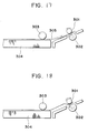
- the sheet supply roller 303 is stopped while abutting against the sheet stacker 304, and then, the convey roller 301 is rotated reversely, thereby returning the leading end of the recording medium 305 to a position upstream of the nip between the convey roller 301 and the driven roller 302 (Figs. 18 and 19).
- the leading end of the recording medium is returned toward the upstream side from the nip between the convey roller 301 and the driven roller 302, and then, is abutted against the nip, thereby preventing the skew feed of the recording medium.
- the skew feed preventing ability is highly ensured in case of the cut sheet and the like a thickness of which is uniformly controlled, regarding sheets having no uniform thickness such as envelopes folded several times over and having different thickness folded portions, as shown in Fig.
- this feeding method causes skew feed of the sheet more noticeably than in the case where the sheet is directly forwarded without returning it toward the upstream side.
- the document EP-A-0 418 515 discloses a sheet feeding apparatus which comprises a single motor driving a first feeding means via a non-reversing clutch, and a second feeding means.
- the motor drives the first and second feeding means in a sheet advancing direction until the leading edge of the sheet is advanced into and past a nip of the second feeding means.
- the motor is then reversed so that the second feeding means retracts the sheet. Since the first feeding means is not driven in the reverse direction due to the provision of the non-reversing clutch, the sheet bends to form a loop between the first and the second feeding means. This loop tends to align the leading edge of the sheet with the nip, whereupon the motor is reversed again to feed the aligned sheet to the printing position.
- the document JP-A-62 259 944 which forms the preamble portion of claim 1, discloses a sheet feeding apparatus which comprises a first feeding means for feeding a sheet and a second feeding means disposed at a downstream side of the first feeding means for pinching and feeding the sheet.
- the first and second feeding means are controlled such that the sheet is fed by the first feeding means in a predetermined direction until it abuts against the second feeding means and bends to form a loop. Then both the first and second feeding means further feed the sheet until it reaches a sensor.
- both the first and second feeding means are reversed feeding the sheet back to the first feeding means, whereupon the same operation as that set forth above is repeated until the sheet is no longer skew fed (first mode). If the sheet is fed normally until it reaches the sensor for the first time, it is further fed by the first and second feeding means in the predetermined direction to an image forming means (second mode).
- the object of the present invention is to further develop the sheet feeding apparatus and the image forming system, respectively, according to the document JP-A-62 259 944 to the effect that the sheet feeding apparatus is less bulky, whilst the skew feeding of sheets is reliably prevented.
- the sheet feeding apparatus is provided with an urging means adapted to urge the sheet against the first feeding means such that the first feeding means allows the sheet returned in the reverse direction by the second feeding means to move through between the first feeding means and the urging means in the reverse direction, whilst the first feeding means and the urging means afford a frictional resistance to the sheet without flexing it.
- the sheet feeding apparatus as a whole can be kept small-sized since, besides the space for the sheet feeding path as such, no additional space is required between the first and second feeding means.
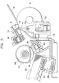
- Fig. 1 is a schematic elevational sectional view of a main portion of a recording system into which a sheet feeding apparatus according to the present invention is incorporated.
- An ink jet recording head 1 is mounted on a carriage 2.
- the carriage 2 is shifted in a main scanning direction perpendicular to a plane of Fig. 1 along a carriage shaft 3, the recording head 1 is moved for the main scan.
- An ink tank 4 serves to reserve ink which is supplied to the recording head 1 via an ink pipe 5.
- a paper guide (platen plate) 10 serves to define a position (printing station or sheet processing station) in which an image is printed or recorded on a recording sheet by the recording head 1.
- the recording head 1 is disposed in confronting relation to the paper guide with a small gap therebetween and is moved along a surface of the paper guide.
- a sheet stacker 21 is arranged in an inclined relation so that it is inclined downwardly and forwardly. The sheet stacker is normally biased upwardly by a spring 39. Recording sheets 22 are rested and stacked on the sheet stacker 21.
- a semi-circular sheet supply roller (first sheet feeding means) 17 is fixedly mounted on a sheet supply roller shaft 32.
- Idle rollers 18 are disposed on both sides of the sheet supply roller 17 and are idly mounted on the sheet supply roller shaft 32.
- the diameters of the idle rollers 18 are smaller than a diameter of the sheet supply roller 17.
- a friction member (friction pad) 19 is disposed below the sheet supply roller 17 and is always biased upwardly by a spring 20 so that it is urged against the idle rollers 18 or a cylindrical portion of the semi-circular sheet supply roller 17.
- a pair of rollers 6, 7 which are urged against each other constitute a second sheet feeding means.
- the lower large roller 6 acts as a driving roller (referred to as “convey roller” hereinafter) and the upper small roller 7 acts as a driven roller.
- the upper driven roller 7 is held by a holder member 13 which is biased toward the lower convey roller 6 by a spring 14 so that the driven roller 7 is urged against the convey roller 6.
- a pair of ejector rollers comprise a lower driving roller 8 and an upper driven roller 9.
- the upper driven roller 9 is held by a holder member 15 which is biased toward the lower driving roller 8 by a spring 16 so that the upper driven roller 9 is urged against the lower driving roller 8.
- the reference numeral 23 denotes an ejection sheet stacker.
- a sensor lever 11 and a photosensor 12 are disposed at a downstream side of a nip N between the paired rollers (second sheet feeding means) 6, 7 to detect a leading end and a trailing end of the recording sheet.
- Fig. 2 shows a gear train of a drive mechanism.
- the reference numeral 24 denotes a pulse motor (sub scan drive motor) as a drive source
- 25 denotes a motor gear secured to an output shaft of the pulse motor
- 26 denotes a convey roller gear secured to a roller shaft of the convey roller 6 of the paired rollers (second sheet feeding means) 6,
- 31 denotes a sheet supply roller gear (clutch gear) idly mounted on the roller shaft 32 of the sheet supply roller (first sheet feeding means) 17,
- 28 denotes an ejector roller gear secured to a roller shaft of the driving roller 8 of the paired ejector rollers 8, 9.
- the motor gear 25 is meshed with the convey roller gear 26 which is in turn drivingly connected to the sheet supply roller gear 31 via idle gears 29, 30, and which is also drivingly connected to the ejector roller gear 28 via an idle gear 27.
- the convey roller gear 26 when the motor gear 25 is rotated normally in a direction shown by the arrow a by the normal rotation of the motor 24, the convey roller gear 26, the sheet supply roller gear 31 and the ejector roller gear 28 are also rotated in normal directions.
- the sheet supply roller 17 is rotated in a normal direction (sub scanning direction) to feed out the recording sheet when a spring clutch 40 (described later) is in a clutch-ON condition.
- the convey roller 6 and the ejector roller 8 are also rotated in normal rotational directions to advance the recording sheet.
- Fig. 3 is a side view of the spring clutch 40 provided on the sheet supply roller shaft 32
- Fig. 4 is a sectional view taken along the line 4 - 4 in Fig. 3.
- the sheet supply roller gear 31 is idly mounted on the sheet supply roller gear 32 as mentioned above.
- a clutch drum 33 is disposed in confronting relation to the sheet supply roller gear 31 and is also mounted on the sheet supply roller shaft 32, which clutch drum 33 is prevented from rotating with respect to the sheet supply roller shaft 32 by an idle rotation preventing pin 34.
- a cam portion 33A is integrally formed with the clutch drum 33. The clutch drum 33 and the sheet supply roller gear 31 are prevented from shifting in the thrust direction by stopper members 37, 38, respectively.
- a coil clutch spring 36 is arranged around both a hub 33a of the clutch drum 33 and a hub 31a of the sheet supply roller gear 31, and a control ring 35 is arranged around the clutch spring 36.
- One end (near the clutch drum 33) of the clutch spring 36 is attached to the clutch drum 33 and the other end (near the sheet supply roller gear 31) of the clutch spring 36 is attached to the control ring 35.
- a lock lever 35A is secured to the control ring 35 and can be locked by a stopper 41 which can be pivoted by an electromagnetic solenoid (not shown).
- the present invention can be applied to various recording systems such as wire dot recording systems, laser beam recording systems, thermal transfer recording systems and the like, as well as the ink jet recording systems, regardless of the types of the recording means (recording heads), with providing the same advantages.
- the recording system of serial type in which the recording head(s) mounted on the carriage is shifted in the main scanning direction along the recording sheet was explained
- the present invention can similarly be applied to recording systems of line type in which the recording is effected by a recording means of line type through the whole or part of the recording width of the recording sheet, with providing the same advantages.
- the present invention can be applied to a mono-color recording system utilizing a single head or a gradient color utilizing a plurality of recording heads for same color inks having different density, or the like, regardless of the number of recording heads, with providing the same advantages.
- the recording head it may be formed integrally with an ink tank to constitute a cartridge or it may be formed independently from an ink tank and connected to the latter via an ink supply tube, regardless of the relation between the recording head and the ink tank, with providing the same advantages.
- the present invention when applied to the ink jet recording systems, it can be applied to an ink jet recording system having a recording head utilizing electrical/thermal converters such as piezo electric elements.
- the present invention when the present invention is applied to an ink jet recording head having a recording means of the type in which the ink is discharged by utilizing thermal energy, the excellent advantage can be expected, since it is possible to achieve the recording with high density and high resolving power.
- bubbles can be respectively formed in liquid (ink) in response to the drive signals. Due to the enlargement and contraction of the bubble, liquid (ink) is discharged through the discharge port, so that at least one droplet is formed.
- the aforementioned drive signal is made to be a pulse signal
- a further satisfactory effect can be obtained in that the bubble can immediately and properly be enlarged/contract and liquid (ink) can be discharged while exhibiting excellent responsibility.
- a further excellent recording operation can be performed.
- the present invention can effectively be used with a recording head of full-line type having a length corresponding to a maximum width of a recording sheet (recording medium) to be recorded.
- recording head the construction in which such length is attained by combining a plurality of recording heads or a single recording head integrally formed may be adopted.
- the present invention can effectively be used with a recording head secured to the recording system, or to a removable recording head of chip type in which, when mounted on the recording system, electrical connection between it and the recording system and the supply of ink from the recording system can be permitted, or to a recording head of cartridge type in which an ink tank is integrally formed with the head.
- a head recovering means and an auxiliary aiding means are added to the recording head. More concretely, these means include a capping means for capping the recording head, cleaning means, pressurizing or suction means, and an auxiliary heating means comprising electrical/thermal converters or other heating elements or the combination thereof. Further, it is effective for the stable recording to perform an auxiliary discharge mode in which the ink discharge regardless of the recording ink discharge is effected.
- each recording head may correspond to each different color ink, or a plurality of recording heads can be used for a plurality of inks having different colors and/or different density. That is to say, as the recording mode of the recording system, the present invention can effectively be used not only with a recording mode with a single main color such as black, but also with a system providing a plurality of different colors and/or a full-color by mixing colors by using an integrated recording head or the combination of plural recording heads.
- the ink while the ink was liquid, the ink may be solid in a room temperature or less, or may be softened at a room temperature.
- the temperature control since the temperature control is generally effected in a temperature range from 30°C to 70°C so that the viscosity of the ink is maintained within a stable discharging range, the ink may be liquidized when the record signal is emitted.
- ink having the feature that it is firstly liquidized by the thermal energy such as solid ink which serves to prevent the increase in temperature by absorbing energy in changing the ink from the solid state to the liquid state, or which is in the solid state in the preserved condition to prevent the vaporization of ink and which is liquidized into ink liquid to be discharged in response to the record signal comprising the thermal energy, or ink which has already been solidified upon reaching the recording medium, can also be used with the present invention.
- the ink jet recording system according to the present invention can be embodied as an image output terminal of an information processing equipment such as a computer, a copying machine combined with a reader and the like, a facsimile having the communication ability, or the like.
Abstract
Description
- The present invention relates to a sheet feeding apparatus according to the preamble portion of
claim 1, for feeding a sheet (normal sheet, cut sheet, print sheet, transfer sheet, photosensitive sheet, electrostatic recording sheet, printing sheet, OHP sheet, envelope, post card, original and the like), whilst preventing the skew feed of the sheet to a sheet processing station such as a printing station, image forming station, exposure station, working station and the like in an image forming system and other various sheet using devices such as a recording system (printer), copying machine, facsimile and the like as an information output equipment such as a word processor, computer and the like. The invention further relates to an image forming system using such sheet feeding apparatus. - In the past, various means for feeding a sheet, whilst preventing the skew feed of the sheet to a sheet processing station such as a printing station of a recording system have been proposed. In an exemplary sheet feeding means, the skew feed of the sheet is prevented by utilizing flexion reactive force of the sheet. That is to say, the sheet feeding means comprises a first sheet feeding means for feeding a sheet to a sheet processing station, and a second sheet feeding means including a pair of urgingly contacted rollers disposed between the first sheet feeding means and the sheet processing station. The sheet feeding means is so designed that a leading end of the sheet is abutted against a nip between the paired rollers of the second sheet feeding means now stopped by the normal rotation of the first sheet feeding means, and that a further normal rotation of the first sheet feeding means forms a predetermined loop in the sheet between the first and second sheet feeding means against the resilience of the sheet. With this arrangement, even when the sheet is skew-fed from the first sheet feeding means, the whole length of the leading end of the sheet is abutted against the nip line between the paired rollers of the second sheet feeding means, thereby registering the leading end of the sheet with the nip line. Then, when the paired rollers of the second sheet feeding means are rotated in the normal direction, the leading end of the sheet enters into the nip of the paired rollers in parallel with the nip line, with the result that the sheet is sent to the sheet processing station without the skew feed of the sheet.
- On the other hand, there are conventional sheet feeding apparatuses in which the first and second sheet feeding means are operated as follows.
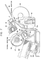
- In Fig. 17, the
reference numeral 303 denotes a sheet supply roller, 304 denotes a sheet stacker, 305 denotes a recording medium, 301 denotes a convey roller, and 302 denotes a driven roller. When thesheet supply roller 303 and theconvey roller 301 are rotated in the normal direction, therecording medium 305 on thesheet stacker 304 is picked up. Theserollers recording medium 305 has passed through a nip between theconvey roller 301 and the drivenroller 302. Thereafter, thesheet supply roller 303 is stopped while abutting against thesheet stacker 304, and then, theconvey roller 301 is rotated reversely, thereby returning the leading end of therecording medium 305 to a position upstream of the nip between theconvey roller 301 and the driven roller 302 (Figs. 18 and 19). In this condition, since a trailing end of therecording sheet 305 is pinched between thesheet supply roller 303 and thesheet stacker 304 urged against the sheet supply roller which are now stationary, the recording medium is flexed or bent between thesheet supply roller 303 and theconvey roller 301 by an amount corresponding to the returning distance of the leading end of the recording medium, with the result that the leading end of the recording medium is wholly abutted against the nip line between theconvey roller 301 and the drivenroller 302. Thereafter, by rotating theconvey roller 301 and thesheet supply roller 303 normally by a predetermined amount, the recording medium is fed to a printing position. - However, in the above-mentioned sheet feeding apparatus and its control, the leading end of the recording medium is returned toward the upstream side from the nip between the
convey roller 301 and the drivenroller 302, and then, is abutted against the nip, thereby preventing the skew feed of the recording medium. Thus, although the skew feed preventing ability is highly ensured in case of the cut sheet and the like a thickness of which is uniformly controlled, regarding sheets having no uniform thickness such as envelopes folded several times over and having different thickness folded portions, as shown in Fig. 20, when the leading end of the sheet is returned toward the upstream side from the nip between theconvey roller 301 and the drivenroller 302 and then is abutted against the nip, since positions on the leading end of the sheet are different from point to point along a line perpendicular to a plane of Fig. 20, this feeding method causes skew feed of the sheet more noticeably than in the case where the sheet is directly forwarded without returning it toward the upstream side. Further, regarding sheets having greater thickness and high resilience, when the convey roller is rotated reversely to return the sheet toward the upstream side from the nip between theconvey roller 301 and the drivenroller 302, because of the high resilience of the sheet, the loop cannot be formed in the sheet between the convey roller and the sheet supply roller, but the convey roller is slipped without returning the sheet, with the result that, when the convey roller is then rotated normally by the predetermined amount to send the sheet to the print start position, the sheet will be fed excessively. - Further, in the conventional sheet feeding apparatus having the above-mentioned skew feed preventing ability, a greater space is required between the first and second sheet feeding means for permitting the formation of the predetermined loop in the sheet, because if such a space is small the sheet will be bent or folded. As a result, it was hard to make the apparatus small-sized.
- In this connection, the document EP-A-0 418 515 discloses a sheet feeding apparatus which comprises a single motor driving a first feeding means via a non-reversing clutch, and a second feeding means. To feed a sheet to a printing position, the motor drives the first and second feeding means in a sheet advancing direction until the leading edge of the sheet is advanced into and past a nip of the second feeding means. The motor is then reversed so that the second feeding means retracts the sheet. Since the first feeding means is not driven in the reverse direction due to the provision of the non-reversing clutch, the sheet bends to form a loop between the first and the second feeding means. This loop tends to align the leading edge of the sheet with the nip, whereupon the motor is reversed again to feed the aligned sheet to the printing position.
- Further, the document JP-A-62 259 944 which forms the preamble portion of
claim 1, discloses a sheet feeding apparatus which comprises a first feeding means for feeding a sheet and a second feeding means disposed at a downstream side of the first feeding means for pinching and feeding the sheet. The first and second feeding means are controlled such that the sheet is fed by the first feeding means in a predetermined direction until it abuts against the second feeding means and bends to form a loop. Then both the first and second feeding means further feed the sheet until it reaches a sensor. If the sensor detects that the sheet is skew fed, both the first and second feeding means are reversed feeding the sheet back to the first feeding means, whereupon the same operation as that set forth above is repeated until the sheet is no longer skew fed (first mode). If the sheet is fed normally until it reaches the sensor for the first time, it is further fed by the first and second feeding means in the predetermined direction to an image forming means (second mode). - Although the skew feeding of sheets can reliably be prevented due to the above measures, one particular disadvantage of this state of the art consists again in that a relatively large space is required between the first and second feeding means for permitting the formation of the predetermined loop.
- Therefore, the object of the present invention is to further develop the sheet feeding apparatus and the image forming system, respectively, according to the document JP-A-62 259 944 to the effect that the sheet feeding apparatus is less bulky, whilst the skew feeding of sheets is reliably prevented.
- This object is solved by the features indicated in the characterizing portion of
claim 1 and the features set forth inclaim 6, respectively. Advantageously developed embodiments of the invention are subject-matter ofclaims 2 to 5, 7 and 8. - According to the invention, the sheet feeding apparatus is provided with an urging means adapted to urge the sheet against the first feeding means such that the first feeding means allows the sheet returned in the reverse direction by the second feeding means to move through between the first feeding means and the urging means in the reverse direction, whilst the first feeding means and the urging means afford a frictional resistance to the sheet without flexing it.
- As a result, the sheet feeding apparatus as a whole can be kept small-sized since, besides the space for the sheet feeding path as such, no additional space is required between the first and second feeding means.
-
- Fig. 1 is a schematic sectional view of a main portion of a recording system of serial type into which a sheet feeding apparatus according to the present invention is incorporated;
- Fig. 2 is a view showing a gear train of a drive mechanism;
- Fig. 3 is a side view showing a spring clutch;
- Fig. 4 is a sectional view taken along the line 4 - 4 in Fig. 3;
- Figs. 5 to 11 are elevational sectional views for explaining a sheet supplying operation, where Fig. 5 illustrates a sheet supply waiting condition, Fig. 6 illustrates an initial condition of the sheet supplying operation, Figs. 7 - 9 illustrate intermediate conditions during the sheet supplying operation, Fig. 10 illustrates a condition in which the sheet is fed reversely, and Fig. 11 illustrates a condition in which the sheet is fed normally again;
- Fig. 12 is a flow chart for the sheet supplying operation;
- Figs. 13 to 16 are plan views for explaining a skew feed preventing operation;
- Figs. 17 to 19 are partial sectional views of a conventional sheet feeding apparatus for explaining a sheet supplying operation; and
- Fig. 20 is a partial sectional view of the conventional sheet feeding apparatus in a condition in which an envelope is supplied.
- First of all, a general construction of a recording system will be explained.
- Fig. 1 is a schematic elevational sectional view of a main portion of a recording system into which a sheet feeding apparatus according to the present invention is incorporated.
- An ink
jet recording head 1 is mounted on acarriage 2. When thecarriage 2 is shifted in a main scanning direction perpendicular to a plane of Fig. 1 along acarriage shaft 3, therecording head 1 is moved for the main scan. Anink tank 4 serves to reserve ink which is supplied to therecording head 1 via anink pipe 5. - A paper guide (platen plate) 10 serves to define a position (printing station or sheet processing station) in which an image is printed or recorded on a recording sheet by the
recording head 1. Therecording head 1 is disposed in confronting relation to the paper guide with a small gap therebetween and is moved along a surface of the paper guide. Asheet stacker 21 is arranged in an inclined relation so that it is inclined downwardly and forwardly. The sheet stacker is normally biased upwardly by aspring 39.Recording sheets 22 are rested and stacked on thesheet stacker 21. - A semi-circular sheet supply roller (first sheet feeding means) 17 is fixedly mounted on a sheet
supply roller shaft 32. Idle rollers 18 (see Fig. 13) are disposed on both sides of thesheet supply roller 17 and are idly mounted on the sheetsupply roller shaft 32. The diameters of theidle rollers 18 are smaller than a diameter of thesheet supply roller 17. A friction member (friction pad) 19 is disposed below thesheet supply roller 17 and is always biased upwardly by aspring 20 so that it is urged against theidle rollers 18 or a cylindrical portion of the semi-circularsheet supply roller 17. - A pair of
rollers large roller 6 acts as a driving roller (referred to as "convey roller" hereinafter) and the uppersmall roller 7 acts as a driven roller. The upper drivenroller 7 is held by aholder member 13 which is biased toward the lower conveyroller 6 by aspring 14 so that the drivenroller 7 is urged against the conveyroller 6. - A pair of ejector rollers comprise a
lower driving roller 8 and an upper drivenroller 9. The upper drivenroller 9 is held by aholder member 15 which is biased toward thelower driving roller 8 by aspring 16 so that the upper drivenroller 9 is urged against thelower driving roller 8. Incidentally, thereference numeral 23 denotes an ejection sheet stacker. - A
sensor lever 11 and a photosensor 12 are disposed at a downstream side of a nip N between the paired rollers (second sheet feeding means) 6, 7 to detect a leading end and a trailing end of the recording sheet. - Next, a drive and drive transmitting mechanism will be explained with reference to Figs. 2 to 4.
- Fig. 2 shows a gear train of a drive mechanism. In Fig. 2, the
reference numeral 24 denotes a pulse motor (sub scan drive motor) as a drive source, 25 denotes a motor gear secured to an output shaft of the pulse motor, 26 denotes a convey roller gear secured to a roller shaft of the conveyroller 6 of the paired rollers (second sheet feeding means) 6, 7, 31 denotes a sheet supply roller gear (clutch gear) idly mounted on theroller shaft 32 of the sheet supply roller (first sheet feeding means) 17, and 28 denotes an ejector roller gear secured to a roller shaft of the drivingroller 8 of the pairedejector rollers motor gear 25 is meshed with the conveyroller gear 26 which is in turn drivingly connected to the sheetsupply roller gear 31 viaidle gears ejector roller gear 28 via anidle gear 27. - Accordingly, when the
motor gear 25 is rotated normally in a direction shown by the arrow a by the normal rotation of themotor 24, the conveyroller gear 26, the sheetsupply roller gear 31 and theejector roller gear 28 are also rotated in normal directions. As a result, thesheet supply roller 17 is rotated in a normal direction (sub scanning direction) to feed out the recording sheet when a spring clutch 40 (described later) is in a clutch-ON condition. Further, the conveyroller 6 and theejector roller 8 are also rotated in normal rotational directions to advance the recording sheet. - Fig. 3 is a side view of the
spring clutch 40 provided on the sheetsupply roller shaft 32, and Fig. 4 is a sectional view taken along the line 4 - 4 in Fig. 3. In Fig. 3, the sheetsupply roller gear 31 is idly mounted on the sheetsupply roller gear 32 as mentioned above. Aclutch drum 33 is disposed in confronting relation to the sheetsupply roller gear 31 and is also mounted on the sheetsupply roller shaft 32, which clutchdrum 33 is prevented from rotating with respect to the sheetsupply roller shaft 32 by an idlerotation preventing pin 34. Acam portion 33A is integrally formed with theclutch drum 33. Theclutch drum 33 and the sheetsupply roller gear 31 are prevented from shifting in the thrust direction bystopper members - A coil
clutch spring 36 is arranged around both ahub 33a of theclutch drum 33 and ahub 31a of the sheetsupply roller gear 31, and acontrol ring 35 is arranged around theclutch spring 36. One end (near the clutch drum 33) of theclutch spring 36 is attached to theclutch drum 33 and the other end (near the sheet supply roller gear 31) of theclutch spring 36 is attached to thecontrol ring 35. Alock lever 35A is secured to thecontrol ring 35 and can be locked by astopper 41 which can be pivoted by an electromagnetic solenoid (not shown). - In a clutch-OFF condition, the
lock lever 35A of thecontrol ring 35 is held by thestopper 41, thus preventing the rotation of thecontrol ring 35. Consequently, theclutch spring 36 is held in a relaxed condition on thehub 31a of the sheetsupply roller gear 31, whereby the sheetsupply roller gear 31 can be idly rotated on theshaft 32, with the result that the rotation force of thegear 31 is not transmitted to theshaft 32. Thus, even when thegear 31 is rotatingly driven, thesheet supply roller 17 remains in a stopped condition. - When the clutch is turned ON, the
stopper 41 is disengaged from thelock lever 35A of thecontrol ring 35, thus releasing thecontrol ring 35. As a result, theclutch spring 36 is tightened around thehub 31a of the sheetsupply roller gear 31 to theclutch drum 33 via theclutch spring 36, thereby transmitting the rotational force of thegear 31 to theshaft 32 to rotate the latter along with thegear 31. That is to say, thesheet supply roller 17 is rotated. - Next, the control and operation will be explained with reference to Figs. 5 to 11, Fig. 12 and Figs. 13 to 16.
- (a) Fig. 6 shows a main portion of the sheet feeding apparatus in a sheet supply waiting condition.
In this sheet supply waiting condition, the motor 24 (Fig. 2) was turned OFF, and thespring clutch 40 was in the clutch-OFF condition by engaging thelock lever 35A with thestopper 41. Thesheet supply roller 17 was in an angular position where a cut-out portion of the semi-circular sheet supply roller was directed downwardly and was not contacted with thefriction member 19, and this friction member was urged against theidle rollers 18.
Further, thesheet stacker 21 was held in a predetermined lower waiting position by thecam 33A of theclutch drum 33 of thespring clutch 40 in opposition to the biasingspring 39, where the leading upper surface of thesheet stack 22 was not contacted with both theidle rollers 18 and thesheet supply roller 17. - (b) In this sheet supply waiting condition, when a sheet supply start signal is sent to a control means (not shown), the
stopper 41 is disengaged from thelever 35A of thespring clutch 40, thus turning the clutch ON. Further, themotor 24 is rotated normally (steps S1 to S3 in the flow chart in Fig. 12).
As a result, thesheet supply roller 17 starts to rotate normally, and the conveyroller 6 and theejector roller 8 also start to rotate normally. Further, thesheet stacker 21 is released from thecam 33A, thereby lifting thesheet stacker 21 by thespring 39 to urge the leading upper surface of thesheet stack 22 against the cylindrical portion of the rotatingsheet supply roller 17, as shown in Fig. 6. As thesheet supply roller 17 continues to rotate normally, an uppermost sheet on thesheet stack 22 is picked up and supplied. - (c) The supplied sheet enters between the
sheet supply roller 17 and thefriction member 19. In this case, even if the second and other sheets are double-fed together with the uppermost sheet, such second and other sheets are prevented, by thefriction member 19, from passing between thesheet supply roller 17 and thefriction member 19, thereby separating the uppermost sheet from the other sheets and feeding it in the normal direction through the nip between thesheet supply roller 17 and thefriction member 19, as shown in Fig. 7. After the leading end of the uppermost sheet enters into the nip between thesheet supply roller 17 and thefriction member 19, thesheet stacker 21 is lowered again to the predetermined waiting position by thecam 33A of theclutch drum 33 in opposition to thespring 39, thus releasing the urging force of the spring 39 (urging the sheet stack against the sheet supply roller 17). - (d) The further normal rotation of the
sheet supply roller 17 causes thesheet 22 to be fed in the normal direction. When the leading end of the sheet reaches near the nip N between the conveyroller 6 and the associated driven roller 7 (second sheet feeding means), thesensor lever 11 is moved by the leading end of the sheet to rotate this lever in a clockwise direction around apin 11a, thereby shifting alight blocking flag 11b out of a light path of the photosensor 12 to open this light path (Fig. 8). As a result, thesensor 12 is turned ON to inform the control means of the detection of the leading end (tip end) of the recording sheet (recording material) (step S4 in the flow chart in Fig. 12). This detection signal causes a timer circuit of the control means to be driven. - (e) The sheet is further fed in the normal direction, and the leading end of the sheet enters into the nip N between the convey
roller 6 and the driven roller 7 (second sheet feeding means) now rotating the normal direction. As shown in Fig. 9, when the leading end of the sheet reaches a predetermined distance L forwardly from the nip N of therollers sensor 12 to when the leading end of the sheet reaches the predetermined distance L forwardly from the nip N of therollers - (f) The motor 24 (Fig. 2) is rotated reversely by a time-up signal emitted when the timer circuit is timed up. At this point, the
uppermost sheet 22 extends between the first sheet feeding means (sheet supply roller 17 and friction member 19) and the second sheet feeding means (conveyroller 6 and driven roller 7) while engaging with them.
When themotor 24 is rotated reversely, the conveyroller gear 26, the sheetsupply roller gear 31 and theejector roller gear 28 are also rotated reversely, thereby rotating the conveyroller 6 and theejector roller 8 reversely. The reverse rotation of the conveyroller 6 causes thesheet 22 to be fed back in a reverse direction. Regarding thesheet supply roller 17, since theclutch spring 36 of thespring clutch 40 is loosened due to the reverse rotation of the sheetsupply roller gear 31, the reverse rotational force of the sheetsupply roller gear 31 is not transmitted to the sheetsupply roller shaft 32. Accordingly, thesheet supply roller 17 is prevented from rotating by the urging force between this roller and thefriction member 19, but is permitted to rotate reversely by an amount corresponding to the loosenedclutch spring 36.
When thesheet 22 is fed back in the reverse direction by the conveyroller 6 now rotating reversely, thesheet supply roller 17 is rotated reversely by the amount corresponding to the loosenedclutch spring 36 against the friction force of this roller and the sheet. Thereafter, since there is no space for permitting the flexion of the sheet between thesheet supply roller 17/friction member 19 and the conveyroller 6/drivenroller 7 and the friction force F2 for thesheet 22 due to the urging force between thesheet supply roller 17 and thefriction member 19 is smaller than the friction force F1 for thesheet 22 due to the urging force between the conveyroller 6 and the drivenroller 7, thesheet 22 is shifted in the reverse direction while slipping between thesheet supply roller 17 and thefriction member 19.
The reverse rotation of themotor 24 is effected by sending to it a number of reverse driving pulses sufficient to feed back the leading end of the sheet projecting from the nip N of therollers - (1) Fig. 13 is a plan view showing the sheet in a condition corresponding to that shown in Fig. 9. In this condition, the leading end of the normally fed
sheet 22 has passed smoothly through the nip N between the conveyroller 6 and the driven roller 7 (second sheet feeding means), and protruded by the predetermined distance L, and the conveyroller 6 has just been switched from its normal rotation to reverse rotation.
This condition shows the fact that thesheet 22 has been skew-fed from thesheet supply roller 17 to the nip between the conveyroller 6 and the drivenroller 7. Since thesheet 22 was skew-fed, onecorner 22a of the leading end of the sheet protrudes from the nip N of therollers other corner 22b of the sheet. - (2) From this condition, the
sheet 22 is shifted in the reverse direction by the reverse rotation of the conveyroller 6. In this case, since the friction force F2 for thesheet 22 due to the urging force between thesheet supply roller 17 and thefriction member 19 is smaller than the friction force F1 for thesheet 22 due to the urging force between the conveyroller 6 and the drivenroller 7, thesheet 22 is shifted in the reverse direction while slipping between thesheet supply roller 17 and thefriction member 19 without forming the loop in the sheet between thesheet supply roller 17/friction member 19 and the conveyroller 6/drivenroller 7. By the reverse shifting of the sheet, theother corner 22b of the leading end of the skew-fedsheet 22 firstly leaves the nip N of therollers other corner 22b has passed through the nip N, thecorner 22b is not subjected to the reverse feeding force from therollers
However, in this point, since the onecorner 22a of the leading end of the sheet is still being shifted reversely between the nip N of therollers sheet 22 is turned in an anti-clockwise direction A around theother corner 22b of the leading end of the sheet which is abutted against the nip line between therollers corner 22a of the leading end of the sheet passes through the nip N of therollers - (3) When the turning movement of the sheet is finished by passing the one
end 22a of the leading end of the sheet through the nip N, as shown in Fig. 15 (corresponding to Fig. 10), the posture of thesheet 22 is corrected so that the whole length of the leading edge of the sheet is abutted against the nip line N of therollers
- (1) Fig. 13 is a plan view showing the sheet in a condition corresponding to that shown in Fig. 9. In this condition, the leading end of the normally fed
- (g) As mentioned above, when the skew-feed of the sheet is corrected by rotating the convey
roller 6 reversely by the amount corresponding to the predetermined number of pulses, themotor 24 is rotated normally again. When themotor 24 is rotated normally again, the conveyroller 6 is rotated in the normal direction to enter the leading end of thesheet 22 into the nip N of therollers sheet 22 is fed normally to aprinting station
The normal rotation of themotor 24 causes the sheetsupply roller gear 31 to rotate normally, thereby rotating thesheet supply roller 17 in the normal direction. In this case, when the sheet supply roller is rotated by a certain angle, the cylindrical portion of the sheet supply roller passes through thefriction member 19 to separate from thesheet 22. From this point, thesheet 22 is pinched between theidle rollers 18 and thefriction member 19, and theidle rollers 18 are rotatingly driven by the normal movement of thesheet 22.
Then, when thesheet supply roller 17 is rotated by one revolution, it is stopped since thelock lever 35A of thespring clutch 40 is engaged by thestopper 41 again to turn the clutch OFF. Even when thesheet supply roller 17 is stopped, thesheet 22 continues to be shifted normally by the normal rotation of the conveyroller 6, and theidle rollers 18 are rotatingly driven until the trailing end of thesheet 22 leaves these rollers.
In the illustrated embodiment, since the recording system is of serial type, the normal re-feeding of the sheet due to the normal re-rotation of themotor 24 is effected until the leading end of the sheet reaches a predetermined printing position. At this point, the re-feeding of the sheet is temporarily stopped (step S7 in the flow chart in Fig. 12). - (h) Thereafter, the sheet is fed to the
printing station sheet 22 by therecording head 1 in the serial manner. - (i) The sheet passed through the
printing station ejector rollers sheet 22 leaves thesensor lever 11, the latter is cocked again, whereby the light path of thephotosensor 12 is blocked by theflag 11b, thereby detecting the passing of the trailing end of the sheet. The detection signal is inputted to the control means. - (j) After the printing is effected on the
first sheet 22 and the latter is ejected onto theejection stacker 23, the control and operation from the above (a) - (i) are repeated to process second, third and other sheets. - Incidentally, in the aforementioned embodiments, while the present invention was applied to the ink jet recording systems, the present invention can be applied to various recording systems such as wire dot recording systems, laser beam recording systems, thermal transfer recording systems and the like, as well as the ink jet recording systems, regardless of the types of the recording means (recording heads), with providing the same advantages. Further, in the aforementioned embodiments, while the recording system of serial type in which the recording head(s) mounted on the carriage is shifted in the main scanning direction along the recording sheet was explained, the present invention can similarly be applied to recording systems of line type in which the recording is effected by a recording means of line type through the whole or part of the recording width of the recording sheet, with providing the same advantages.
- Further, in the aforementioned embodiments, while the color recording systems utilizing a plurality of recording heads for the different colors were explained, the present invention can be applied to a mono-color recording system utilizing a single head or a gradient color utilizing a plurality of recording heads for same color inks having different density, or the like, regardless of the number of recording heads, with providing the same advantages.
- Furthermore, regarding the recording head, it may be formed integrally with an ink tank to constitute a cartridge or it may be formed independently from an ink tank and connected to the latter via an ink supply tube, regardless of the relation between the recording head and the ink tank, with providing the same advantages.
- Incidentally, when the present invention is applied to the ink jet recording systems, it can be applied to an ink jet recording system having a recording head utilizing electrical/thermal converters such as piezo electric elements. Particularly, when the present invention is applied to an ink jet recording head having a recording means of the type in which the ink is discharged by utilizing thermal energy, the excellent advantage can be expected, since it is possible to achieve the recording with high density and high resolving power.
- It is preferable to employ the typical structure and the principle of structures disclosed in, for example, U.S.P. No. 4,723,129 and U.S.P. No. 4,740,796. This system can be adopted in a so-called "On-Demand" type and "Continuous" type structures. In this system, an electrothermal conversion member disposed to align to a sheet or a liquid passage in which liquid (ink) is held, is supplied with at least one drive signal which corresponds to information to be recorded and which enables the temperature of the electrothermal conversion member to be raised higher than a nuclear boiling point, so that thermal energy is generated in the electrothermal conversion member and film boiling is caused to take place on the surface of the recording head which is heated. As a result, bubbles can be respectively formed in liquid (ink) in response to the drive signals. Due to the enlargement and contraction of the bubble, liquid (ink) is discharged through the discharge port, so that at least one droplet is formed. In a case in which the aforementioned drive signal is made to be a pulse signal, a further satisfactory effect can be obtained in that the bubble can immediately and properly be enlarged/contract and liquid (ink) can be discharged while exhibiting excellent responsibility. It is preferable to employ a drive signal of the pulse signal type disclosed in U.S.P. 4,463,359 and U.S.P. 4,345,262. Furthermore, in a case in which conditions for determining the temperature rise ratio on the aforementioned heated surface disclosed in U.S.P. No. 4,313,124 are adopted, a further excellent recording operation can be performed.
- In addition to the structure (a linear liquid passage or a perpendicular liquid passage) of the recording head formed by combining the discharge ports, the liquid passage and the electrothermal conversion member as disclosed in the aforesaid specifications, a structure disclosed in U.S.P. No. 4,558,333 and U.S.P. 4,459,600 in which the heated portion is disposed in a bent portion may be used. Furthermore, the present invention can effectively be embodied in a structure in which a common slit is made to be the discharge portion of a plurality of electrothermal conversion members and which is disclosed in Japanese Patent Laid-Open No. 59-123670, and a structure in which an opening for absorbing thermal energy pressure wave is formed to align to the discharge port and which is disclosed in Japanese Patent Laid-Open No. 59-138461. That is, the recording can be carried out effectively irrespective of the embodiment of the recording head.
- Further, the present invention can effectively be used with a recording head of full-line type having a length corresponding to a maximum width of a recording sheet (recording medium) to be recorded. As such recording head, the construction in which such length is attained by combining a plurality of recording heads or a single recording head integrally formed may be adopted. In addition, among the above-mentioned serial types, the present invention can effectively be used with a recording head secured to the recording system, or to a removable recording head of chip type in which, when mounted on the recording system, electrical connection between it and the recording system and the supply of ink from the recording system can be permitted, or to a recording head of cartridge type in which an ink tank is integrally formed with the head.
- Further, it is preferable that a head recovering means and an auxiliary aiding means are added to the recording head. More concretely, these means include a capping means for capping the recording head, cleaning means, pressurizing or suction means, and an auxiliary heating means comprising electrical/thermal converters or other heating elements or the combination thereof. Further, it is effective for the stable recording to perform an auxiliary discharge mode in which the ink discharge regardless of the recording ink discharge is effected.
- Further, as to the kind and number of the recording head to be mounted, each recording head may correspond to each different color ink, or a plurality of recording heads can be used for a plurality of inks having different colors and/or different density. That is to say, as the recording mode of the recording system, the present invention can effectively be used not only with a recording mode with a single main color such as black, but also with a system providing a plurality of different colors and/or a full-color by mixing colors by using an integrated recording head or the combination of plural recording heads.
- Further, in the illustrated embodiments, while the ink was liquid, the ink may be solid in a room temperature or less, or may be softened at a room temperature. In the above-mentioned ink jet recording system, since the temperature control is generally effected in a temperature range from 30°C to 70°C so that the viscosity of the ink is maintained within a stable discharging range, the ink may be liquidized when the record signal is emitted. In addition, ink having the feature that it is firstly liquidized by the thermal energy, such as solid ink which serves to prevent the increase in temperature by absorbing energy in changing the ink from the solid state to the liquid state, or which is in the solid state in the preserved condition to prevent the vaporization of ink and which is liquidized into ink liquid to be discharged in response to the record signal comprising the thermal energy, or ink which has already been solidified upon reaching the recording medium, can also be used with the present invention.
- In such a case, the ink can be held in the liquid state or solid state in recesses or holes in a porous sheet as disclosed in the Japanese Patent Laid-Open Nos. 54-56847 and 60-71260, in confronting relation to the electrical/thermal converters. Incidentally, the above-mentioned film boiling principle is most effective for each ink. Furthermore, the ink jet recording system according to the present invention can be embodied as an image output terminal of an information processing equipment such as a computer, a copying machine combined with a reader and the like, a facsimile having the communication ability, or the like.
Claims (8)
- A sheet feeding apparatus, comprising a first feeding means (17) for feeding a sheet (22), a second feeding means (6, 7) disposed at a downstream side of said first feeding means (17) and adapted to pinch and feed the sheet (22), and a control means capable of driving said first and second feeding means (6, 7; 17) to feed the sheet (22) in a predetermined direction until a leading end of the sheet (22) passes through a nip (N) of said second feeding means (6, 7) and exceeds said nip (N) by a predetermined distance (L) toward a downstream side whilst the sheet (22) is being urged against said first feeding means (17), subsequently driving said second feeding means (6, 7) in a reverse direction to return the sheet (22) in a reverse direction by a distance longer than said predetermined distance (L), and finally driving said second feeding means (6, 7) to feed the sheet (22) in said predetermined direction, characterized by an urging means (20) adapted to urge the sheet (22) against said first feeding means (17) such that said first feeding means (17) allows the sheet (22) returned in the reverse direction by said second feeding means (6, 7) to move through between said first feeding means (17) and said urging means (20) in the reverse direction, whilst said first feeding means (17) and said urging means (20) afford a frictional resistance to the sheet (22) without flexing it.
- A sheet feeding apparatus according to claim 1, wherein said second feeding means comprises a pair of rollers (6, 7) urged against each other.
- A sheet feeding apparatus according to claim 1 or 2, wherein said first feeding means comprises a roller (17) which cooperates with a friction member (19) to separate the sheets (22).
- A sheet feeding apparatus according to one of the preceding claims, further comprising a drive means (24) for driving said first and second feeding means (6, 7; 17), and drive transmitting means (25 - 31) for transmitting a driving force of said drive means (24) to said first and second feeding means (6, 7; 17).
- A sheet feeding apparatus according to claim 4, wherein said drive means comprises a motor (24).
- An image forming system, comprising a sheet feeding apparatus according to one of the preceding claims, and image forming means (1) for forming an image on the sheet (22) being fed in the predetermined direction by said second feeding means (6, 7).
- An image forming system according to claim 6, wherein said image forming means comprises an ink jet recording head (1).
- An image forming system according to claim 7, wherein said ink jet recording head (1) generates an ink droplet by thermal energy.
Priority Applications (2)
| Application Number | Priority Date | Filing Date | Title |
|---|---|---|---|
| EP96107496A EP0733567B1 (en) | 1991-08-22 | 1992-08-21 | Recording system |
| EP96107495A EP0733566B1 (en) | 1991-08-22 | 1992-08-21 | Sheet feeding apparatus |
Applications Claiming Priority (6)
| Application Number | Priority Date | Filing Date | Title |
|---|---|---|---|
| JP3235519A JP2738181B2 (en) | 1991-08-22 | 1991-08-22 | Sheet conveying device and image forming device |
| JP235519/91 | 1991-08-22 | ||
| JP3234695A JPH0569984A (en) | 1991-09-13 | 1991-09-13 | Sheet conveyance device |
| JP262657/91 | 1991-09-13 | ||
| JP3262657A JP2847445B2 (en) | 1991-09-13 | 1991-09-13 | Recording device |
| JP234695/91 | 1991-09-13 |
Related Child Applications (4)
| Application Number | Title | Priority Date | Filing Date |
|---|---|---|---|
| EP96107495A Division EP0733566B1 (en) | 1991-08-22 | 1992-08-21 | Sheet feeding apparatus |
| EP96107496A Division EP0733567B1 (en) | 1991-08-22 | 1992-08-21 | Recording system |
| EP96107495.2 Division-Into | 1996-05-10 | ||
| EP96107496.0 Division-Into | 1996-05-10 |
Publications (2)
| Publication Number | Publication Date |
|---|---|
| EP0529538A1 EP0529538A1 (en) | 1993-03-03 |
| EP0529538B1 true EP0529538B1 (en) | 1997-07-09 |
Family
ID=27332176
Family Applications (3)
| Application Number | Title | Priority Date | Filing Date |
|---|---|---|---|
| EP96107495A Expired - Lifetime EP0733566B1 (en) | 1991-08-22 | 1992-08-21 | Sheet feeding apparatus |
| EP96107496A Expired - Lifetime EP0733567B1 (en) | 1991-08-22 | 1992-08-21 | Recording system |
| EP92114325A Expired - Lifetime EP0529538B1 (en) | 1991-08-22 | 1992-08-21 | Sheet feeding apparatus and image forming system |
Family Applications Before (2)
| Application Number | Title | Priority Date | Filing Date |
|---|---|---|---|
| EP96107495A Expired - Lifetime EP0733566B1 (en) | 1991-08-22 | 1992-08-21 | Sheet feeding apparatus |
| EP96107496A Expired - Lifetime EP0733567B1 (en) | 1991-08-22 | 1992-08-21 | Recording system |
Country Status (4)
| Country | Link |
|---|---|
| US (3) | US5982400A (en) |
| EP (3) | EP0733566B1 (en) |
| AT (3) | ATE155110T1 (en) |
| DE (3) | DE69231772T2 (en) |
Families Citing this family (46)
| Publication number | Priority date | Publication date | Assignee | Title |
|---|---|---|---|---|
| JP3530543B2 (en) * | 1993-02-25 | 2004-05-24 | セイコーエプソン株式会社 | Cut sheet skew removal method and apparatus |
| JPH07215499A (en) * | 1993-11-01 | 1995-08-15 | At & T Global Inf Solutions Internatl Inc | Document aligning method concerning paper feeding device, paper feeding device and paper pick-up mechanism to be used in said paper feeding device |
| JPH0971333A (en) * | 1995-09-06 | 1997-03-18 | Brother Ind Ltd | Paper feeding device |
| US6059285A (en) | 1996-12-18 | 2000-05-09 | Canon Kabushiki Kaisha | Sheet conveying apparatus |
| US6405152B1 (en) * | 1998-05-18 | 2002-06-11 | Prim Hall Enterprises, Inc. | Precision calipering system |
| US6182961B1 (en) * | 1998-12-16 | 2001-02-06 | Xerox Corporation | Duplex document retard separation and feeding with reduced image smudging |
| US6332665B1 (en) * | 1999-12-20 | 2001-12-25 | Xerox Corporation | Skewed substrate pixel array printing machine |
| JP3762228B2 (en) * | 2001-01-31 | 2006-04-05 | キヤノン株式会社 | Recording apparatus and recording method |
| JP4464003B2 (en) * | 2001-02-28 | 2010-05-19 | キヤノン株式会社 | Recording apparatus and recording method |
| JP3577013B2 (en) | 2001-08-10 | 2004-10-13 | キヤノン株式会社 | Driving method of discharge roller and recording apparatus |
| US6979080B2 (en) * | 2001-08-29 | 2005-12-27 | Brother Kogyo Kabushiki Kaisha | Printer having improved recording medium feeding mechanism |
| ATE342859T1 (en) * | 2001-08-31 | 2006-11-15 | Seiko Epson Corp | RECORDING DEVICE |
| JP3880510B2 (en) | 2002-01-24 | 2007-02-14 | キヤノン株式会社 | Recording apparatus and recording medium type discrimination method |
| JP3919549B2 (en) * | 2002-01-31 | 2007-05-30 | キヤノン株式会社 | Recording device |
| US6612685B1 (en) | 2002-02-11 | 2003-09-02 | Lexmark International, Inc. | Method of selectively underfeeding print media in an ink jet printer |
| ITTO20020304A1 (en) * | 2002-04-08 | 2003-10-08 | Olivetti Tecnost | PAPER FEEDING DEVICE FOR POINT PRINTERS, FOR EXAMPLE INK-JET PHOTOGRAPHIC PRINTERS. |
| JP3766039B2 (en) * | 2002-04-12 | 2006-04-12 | シャープ株式会社 | Paper transport device and printing device |
| US6851802B2 (en) * | 2002-05-02 | 2005-02-08 | Brother Kogyo Kabushiki Kaisha | Image forming device including mechanism to lock cover |
| JP2003329407A (en) * | 2002-05-14 | 2003-11-19 | Sharp Corp | Optical distance measurement device and printing device using the same |
| JP2004043178A (en) * | 2002-05-23 | 2004-02-12 | Ricoh Co Ltd | Automatic document carrying device and image processing device |
| JP4033781B2 (en) * | 2002-05-29 | 2008-01-16 | シャープ株式会社 | Optical object identification device, processing system, and conveyance processing system |
| US6749192B2 (en) * | 2002-06-05 | 2004-06-15 | Hewlett-Packard Development Company, L.P. | Skew correction for a media feed mechanism |
| US7165765B2 (en) * | 2002-06-07 | 2007-01-23 | Canon Kabushiki Kaisha | Sheet feeding apparatus and recording apparatus |
| US6991331B2 (en) * | 2002-06-25 | 2006-01-31 | Canon Kabushiki Kaisha | Recording apparatus |
| JP4078902B2 (en) * | 2002-07-09 | 2008-04-23 | 富士ゼロックス株式会社 | Image reading device |
| JP3882708B2 (en) * | 2002-07-30 | 2007-02-21 | セイコーエプソン株式会社 | Recording apparatus, program, and computer system |
| JP4110907B2 (en) * | 2002-10-02 | 2008-07-02 | セイコーエプソン株式会社 | Recording apparatus, recording method, program, and computer system |
| US6860665B2 (en) * | 2002-10-28 | 2005-03-01 | Hewlett-Packard Development Company, L.P. | Passive linear encoder |
| US6951335B2 (en) | 2002-10-29 | 2005-10-04 | Hewlett-Packard Development Company, L.P. | Reciprocating linear encoder |
| KR100547431B1 (en) * | 2003-08-01 | 2006-01-31 | 엘지엔시스(주) | Thickness Detection Device of Media |
| JP4012130B2 (en) * | 2003-08-20 | 2007-11-21 | キヤノン株式会社 | Recording device and tray |
| US7614736B2 (en) * | 2003-12-19 | 2009-11-10 | Sharp Kabushiki Kaisha | Printing apparatus |
| JP4310218B2 (en) * | 2004-03-19 | 2009-08-05 | キヤノン株式会社 | Document feeder |
| JP4476731B2 (en) * | 2004-07-29 | 2010-06-09 | ニスカ株式会社 | Document feeder |
| JP4613790B2 (en) * | 2004-10-21 | 2011-01-19 | セイコーエプソン株式会社 | Power interrupting mechanism, medium supply device, recording device, and liquid ejecting device |
| JP4401934B2 (en) * | 2004-11-05 | 2010-01-20 | キヤノン株式会社 | Recording apparatus and control method thereof |
| US20070019023A1 (en) * | 2005-07-19 | 2007-01-25 | Weast Aaron B | Stiffness of medium |
| US7717533B2 (en) | 2005-08-30 | 2010-05-18 | Xerox Corporation | Systems and methods for medium registration |
| JP4738997B2 (en) * | 2005-12-01 | 2011-08-03 | 株式会社リコー | Image forming apparatus |
| JP4412287B2 (en) * | 2006-01-26 | 2010-02-10 | ブラザー工業株式会社 | Printing device |
| JP4760402B2 (en) | 2006-01-30 | 2011-08-31 | ブラザー工業株式会社 | Image forming apparatus and control program for image forming apparatus |
| JP4240102B2 (en) * | 2006-09-29 | 2009-03-18 | ブラザー工業株式会社 | Sheet conveying apparatus and sheet conveying method |
| JP5132623B2 (en) | 2008-05-08 | 2013-01-30 | キヤノン株式会社 | Printer |
| JP2017159989A (en) * | 2016-03-09 | 2017-09-14 | キヤノン株式会社 | Sheet conveying device and image forming device |
| JP6758942B2 (en) | 2016-06-17 | 2020-09-23 | キヤノン株式会社 | Conveyor and printing equipment |
| US11091338B2 (en) * | 2019-03-25 | 2021-08-17 | Toshiba Tec Kabushiki Kaisha | Sheet conveying device and sheet conveying method |
Family Cites Families (21)
| Publication number | Priority date | Publication date | Assignee | Title |
|---|---|---|---|---|
| CA1127227A (en) * | 1977-10-03 | 1982-07-06 | Ichiro Endo | Liquid jet recording process and apparatus therefor |
| JPS5936879B2 (en) * | 1977-10-14 | 1984-09-06 | キヤノン株式会社 | Thermal transfer recording medium |
| JPS59108645A (en) * | 1982-12-10 | 1984-06-23 | Fujitsu Ltd | Conveying device for paper sheet |
| JPS59138461A (en) * | 1983-01-28 | 1984-08-08 | Canon Inc | Liquid jet recording apparatus |
| JPS6071360A (en) | 1983-09-27 | 1985-04-23 | Toyota Motor Corp | Hydraulic braking device for automobile |
| JPS6071260A (en) * | 1983-09-28 | 1985-04-23 | Erumu:Kk | Recorder |
| JPS60244726A (en) * | 1984-05-17 | 1985-12-04 | Usac Electronics Ind Co Ltd | Paper feeder |
| JPH0694013B2 (en) * | 1985-08-08 | 1994-11-24 | 株式会社ニレコ | Paint supply equipment |
| US4664369A (en) * | 1985-10-01 | 1987-05-12 | Diebold Incorporated | Multiple sheet indicator apparatus and method |
| JPS62259944A (en) * | 1986-04-30 | 1987-11-12 | Nec Corp | Paper skew compensating mechanism |
| JPH01214541A (en) * | 1988-02-22 | 1989-08-28 | Canon Inc | Sheet feed device |
| KR940010881B1 (en) * | 1988-10-07 | 1994-11-19 | 캐논 가부시끼가이샤 | Recording apparatus |
| JP2801282B2 (en) * | 1989-09-18 | 1998-09-21 | キヤノン株式会社 | Recording device |
| US4990011A (en) * | 1989-09-21 | 1991-02-05 | Hewlett-Packard Company | Sheet alignment using reverse advance roll and stationary pick roll |
| JPH0810813Y2 (en) * | 1989-11-17 | 1996-03-29 | 日立工機株式会社 | Paper transport device for printing equipment |
| JP2731963B2 (en) * | 1989-12-07 | 1998-03-25 | 株式会社日立製作所 | Paper attitude control device and printer |
| US5602571A (en) | 1990-03-14 | 1997-02-11 | Canon Kabushiki Kaisha | Sheet feeding apparatus and recording system with it |
| JP2963723B2 (en) * | 1990-04-20 | 1999-10-18 | キヤノン株式会社 | Cut sheet separation device |
| JPH04213546A (en) * | 1990-06-05 | 1992-08-04 | Seiko Epson Corp | Recording medium discharge mechanism for printer |
| US5240241A (en) * | 1990-10-31 | 1993-08-31 | Canon Kabushiki Kaisha | Sheet feeding apparatus |
| EP0528434B1 (en) * | 1991-08-21 | 1998-11-11 | Canon Kabushiki Kaisha | Automatic sheet feeding apparatus |
-
1992
- 1992-08-20 US US07/932,569 patent/US5982400A/en not_active Expired - Lifetime
- 1992-08-21 EP EP96107495A patent/EP0733566B1/en not_active Expired - Lifetime
- 1992-08-21 AT AT92114325T patent/ATE155110T1/en not_active IP Right Cessation
- 1992-08-21 AT AT96107495T patent/ATE200261T1/en not_active IP Right Cessation
- 1992-08-21 EP EP96107496A patent/EP0733567B1/en not_active Expired - Lifetime
- 1992-08-21 AT AT96107496T patent/ATE198586T1/en active
- 1992-08-21 EP EP92114325A patent/EP0529538B1/en not_active Expired - Lifetime
- 1992-08-21 DE DE69231772T patent/DE69231772T2/en not_active Expired - Lifetime
- 1992-08-21 DE DE69231638T patent/DE69231638T2/en not_active Expired - Lifetime
- 1992-08-21 DE DE69220734T patent/DE69220734T2/en not_active Expired - Lifetime
-
1995
- 1995-06-06 US US08/467,166 patent/US6257692B1/en not_active Expired - Lifetime
- 1995-06-06 US US08/468,423 patent/US6092893A/en not_active Expired - Fee Related
Also Published As
| Publication number | Publication date |
|---|---|
| EP0529538A1 (en) | 1993-03-03 |
| DE69231638D1 (en) | 2001-02-15 |
| EP0733567B1 (en) | 2001-01-10 |
| US6257692B1 (en) | 2001-07-10 |
| ATE155110T1 (en) | 1997-07-15 |
| EP0733566B1 (en) | 2001-04-04 |
| EP0733566A2 (en) | 1996-09-25 |
| EP0733567A2 (en) | 1996-09-25 |
| DE69220734T2 (en) | 1998-01-15 |
| DE69220734D1 (en) | 1997-08-14 |
| DE69231772D1 (en) | 2001-05-10 |
| DE69231772T2 (en) | 2001-10-11 |
| US5982400A (en) | 1999-11-09 |
| EP0733566A3 (en) | 1996-12-11 |
| US6092893A (en) | 2000-07-25 |
| EP0733567A3 (en) | 1996-12-11 |
| ATE200261T1 (en) | 2001-04-15 |
| DE69231638T2 (en) | 2001-06-07 |
| ATE198586T1 (en) | 2001-01-15 |
Similar Documents
| Publication | Publication Date | Title |
|---|---|---|
| EP0529538B1 (en) | Sheet feeding apparatus and image forming system | |
| EP0658433B1 (en) | Sheet feeding and skew-feed correction apparatus | |
| JPH08277046A (en) | Paper supply and conveyance device and recorder therewith | |
| JPH10128964A (en) | Ink jet recording device | |
| JP2002361958A (en) | Recorder and recording method | |
| JP3684159B2 (en) | Recording apparatus and recording method | |
| JP2005074808A (en) | Recording device | |
| JP5289021B2 (en) | Inkjet recording device | |
| JP3495932B2 (en) | Sheet feeding device and recording device | |
| US7046380B2 (en) | Recording apparatus with feed control based on leading end margin amount | |
| JPH07149009A (en) | Ink jet recording apparatus | |
| JP3530675B2 (en) | Ink jet recording device | |
| JPH0826532A (en) | Recorder device | |
| JPH054397A (en) | Sheet feeder and recording device with the same sheet feeder | |
| JP2837974B2 (en) | Automatic paper feeder | |
| JP2001138600A (en) | Recorder | |
| JP2938681B2 (en) | Automatic feeding device and image forming device | |
| JP3015142B2 (en) | Automatic paper feeder and recording device | |
| JP2738181B2 (en) | Sheet conveying device and image forming device | |
| JPH08198492A (en) | Sheet conveyance device and recorder | |
| JP2001310833A (en) | Recording device | |
| JP2007119190A (en) | Recording device | |
| JP2002211062A (en) | Ink jet recorder | |
| JPH05330685A (en) | Automatic paper feeding device and image forming device | |
| JPH09240853A (en) | Paper feeder and recorder |
Legal Events
| Date | Code | Title | Description |
|---|---|---|---|
| PUAI | Public reference made under article 153(3) epc to a published international application that has entered the european phase |
Free format text: ORIGINAL CODE: 0009012 |
|
| AK | Designated contracting states |
Kind code of ref document: A1 Designated state(s): AT BE CH DE DK ES FR GB GR IT LI LU MC NL PT SE |
|
| 17P | Request for examination filed |
Effective date: 19930720 |
|
| 17Q | First examination report despatched |
Effective date: 19940822 |
|
| GRAG | Despatch of communication of intention to grant |
Free format text: ORIGINAL CODE: EPIDOS AGRA |
|
| GRAH | Despatch of communication of intention to grant a patent |
Free format text: ORIGINAL CODE: EPIDOS IGRA |
|
| GRAH | Despatch of communication of intention to grant a patent |
Free format text: ORIGINAL CODE: EPIDOS IGRA |
|
| GRAA | (expected) grant |
Free format text: ORIGINAL CODE: 0009210 |
|
| AK | Designated contracting states |
Kind code of ref document: B1 Designated state(s): AT BE CH DE DK ES FR GB GR IT LI LU MC NL PT SE |
|
| DX | Miscellaneous (deleted) | ||
| PG25 | Lapsed in a contracting state [announced via postgrant information from national office to epo] |
Ref country code: NL Free format text: LAPSE BECAUSE OF FAILURE TO SUBMIT A TRANSLATION OF THE DESCRIPTION OR TO PAY THE FEE WITHIN THE PRESCRIBED TIME-LIMIT Effective date: 19970709 Ref country code: ES Free format text: THE PATENT HAS BEEN ANNULLED BY A DECISION OF A NATIONAL AUTHORITY Effective date: 19970709 Ref country code: DK Effective date: 19970709 Ref country code: GR Free format text: LAPSE BECAUSE OF FAILURE TO SUBMIT A TRANSLATION OF THE DESCRIPTION OR TO PAY THE FEE WITHIN THE PRESCRIBED TIME-LIMIT Effective date: 19970709 Ref country code: LI Free format text: LAPSE BECAUSE OF FAILURE TO SUBMIT A TRANSLATION OF THE DESCRIPTION OR TO PAY THE FEE WITHIN THE PRESCRIBED TIME-LIMIT Effective date: 19970709 Ref country code: CH Free format text: LAPSE BECAUSE OF FAILURE TO SUBMIT A TRANSLATION OF THE DESCRIPTION OR TO PAY THE FEE WITHIN THE PRESCRIBED TIME-LIMIT Effective date: 19970709 Ref country code: AT Effective date: 19970709 Ref country code: BE Effective date: 19970709 |
|
| REF | Corresponds to: |
Ref document number: 155110 Country of ref document: AT Date of ref document: 19970715 Kind code of ref document: T |
|
| REG | Reference to a national code |
Ref country code: CH Ref legal event code: EP |
|
| REF | Corresponds to: |
Ref document number: 69220734 Country of ref document: DE Date of ref document: 19970814 |
|
| PG25 | Lapsed in a contracting state [announced via postgrant information from national office to epo] |
Ref country code: LU Free format text: LAPSE BECAUSE OF NON-PAYMENT OF DUE FEES Effective date: 19970831 |
|
| ET | Fr: translation filed | ||
| ITF | It: translation for a ep patent filed |
Owner name: SOCIETA' ITALIANA BREVETTI S.P.A. |
|
| PG25 | Lapsed in a contracting state [announced via postgrant information from national office to epo] |
Ref country code: SE Effective date: 19971009 |
|
| PG25 | Lapsed in a contracting state [announced via postgrant information from national office to epo] |
Ref country code: PT Effective date: 19971016 |
|
| NLV1 | Nl: lapsed or annulled due to failure to fulfill the requirements of art. 29p and 29m of the patents act | ||
| REG | Reference to a national code |
Ref country code: CH Ref legal event code: PL |
|
| PG25 | Lapsed in a contracting state [announced via postgrant information from national office to epo] |
Ref country code: MC Free format text: LAPSE BECAUSE OF NON-PAYMENT OF DUE FEES Effective date: 19980228 |
|
| PLBE | No opposition filed within time limit |
Free format text: ORIGINAL CODE: 0009261 |
|
| STAA | Information on the status of an ep patent application or granted ep patent |
Free format text: STATUS: NO OPPOSITION FILED WITHIN TIME LIMIT |
|
| 26N | No opposition filed | ||
| REG | Reference to a national code |
Ref country code: GB Ref legal event code: IF02 |
|
| PGFP | Annual fee paid to national office [announced via postgrant information from national office to epo] |
Ref country code: IT Payment date: 20080820 Year of fee payment: 17 Ref country code: FR Payment date: 20080821 Year of fee payment: 17 |
|
| REG | Reference to a national code |
Ref country code: FR Ref legal event code: ST Effective date: 20100430 |
|
| PG25 | Lapsed in a contracting state [announced via postgrant information from national office to epo] |
Ref country code: FR Free format text: LAPSE BECAUSE OF NON-PAYMENT OF DUE FEES Effective date: 20090831 |
|
| PGFP | Annual fee paid to national office [announced via postgrant information from national office to epo] |
Ref country code: DE Payment date: 20100831 Year of fee payment: 19 |
|
| PGFP | Annual fee paid to national office [announced via postgrant information from national office to epo] |
Ref country code: GB Payment date: 20100826 Year of fee payment: 19 |
|
| PG25 | Lapsed in a contracting state [announced via postgrant information from national office to epo] |
Ref country code: IT Free format text: LAPSE BECAUSE OF NON-PAYMENT OF DUE FEES Effective date: 20090821 |
|
| GBPC | Gb: european patent ceased through non-payment of renewal fee |
Effective date: 20110821 |
|
| REG | Reference to a national code |
Ref country code: DE Ref legal event code: R119 Ref document number: 69220734 Country of ref document: DE Effective date: 20120301 |
|
| PG25 | Lapsed in a contracting state [announced via postgrant information from national office to epo] |
Ref country code: GB Free format text: LAPSE BECAUSE OF NON-PAYMENT OF DUE FEES Effective date: 20110821 |
|
| PG25 | Lapsed in a contracting state [announced via postgrant information from national office to epo] |
Ref country code: DE Free format text: LAPSE BECAUSE OF NON-PAYMENT OF DUE FEES Effective date: 20120301 |