EP0530485A2 - Squeeze-to-release quick connector - Google Patents
Squeeze-to-release quick connector Download PDFInfo
- Publication number
- EP0530485A2 EP0530485A2 EP92112668A EP92112668A EP0530485A2 EP 0530485 A2 EP0530485 A2 EP 0530485A2 EP 92112668 A EP92112668 A EP 92112668A EP 92112668 A EP92112668 A EP 92112668A EP 0530485 A2 EP0530485 A2 EP 0530485A2
- Authority
- EP
- European Patent Office
- Prior art keywords
- body portion
- retaining ring
- quick connector
- axially
- beam members
- Prior art date
- Legal status (The legal status is an assumption and is not a legal conclusion. Google has not performed a legal analysis and makes no representation as to the accuracy of the status listed.)
- Granted
Links
Images

Classifications
-
- F—MECHANICAL ENGINEERING; LIGHTING; HEATING; WEAPONS; BLASTING
- F16—ENGINEERING ELEMENTS AND UNITS; GENERAL MEASURES FOR PRODUCING AND MAINTAINING EFFECTIVE FUNCTIONING OF MACHINES OR INSTALLATIONS; THERMAL INSULATION IN GENERAL
- F16L—PIPES; JOINTS OR FITTINGS FOR PIPES; SUPPORTS FOR PIPES, CABLES OR PROTECTIVE TUBING; MEANS FOR THERMAL INSULATION IN GENERAL
- F16L37/00—Couplings of the quick-acting type
- F16L37/08—Couplings of the quick-acting type in which the connection between abutting or axially overlapping ends is maintained by locking members
- F16L37/084—Couplings of the quick-acting type in which the connection between abutting or axially overlapping ends is maintained by locking members combined with automatic locking
-
- Y—GENERAL TAGGING OF NEW TECHNOLOGICAL DEVELOPMENTS; GENERAL TAGGING OF CROSS-SECTIONAL TECHNOLOGIES SPANNING OVER SEVERAL SECTIONS OF THE IPC; TECHNICAL SUBJECTS COVERED BY FORMER USPC CROSS-REFERENCE ART COLLECTIONS [XRACs] AND DIGESTS
- Y10—TECHNICAL SUBJECTS COVERED BY FORMER USPC
- Y10S—TECHNICAL SUBJECTS COVERED BY FORMER USPC CROSS-REFERENCE ART COLLECTIONS [XRACs] AND DIGESTS
- Y10S285/00—Pipe joints or couplings
- Y10S285/921—Snap-fit
Definitions
- the present invention relates to snap-fit connectors, and more particularly to such connectors which are employed in fluid conduit systems to facilitate assembly and disassembly.
- Snap-fit or quick connectors have been found to be useful in a wide range of applications. In particular, they are frequently employed for joining fluid carrying conduit in automotive and industrial applications. Such connectors have found general acceptance in as they are typically capable of being closed in a single uniaxial movement which facilitates automated assembly, and entail simple designs which are relatively inexpensive to produce.
- a further advantage of quick connect fittings is that they provide an effective seal for handling volatile or hazardous fluids such as gasoline while permitting ease of disassembly and reassembly during repair of a host system.
- tools are often required to effect release of quick connect fittings, designs such as those described in United States patents 3,990,727 and 4,844,512 provide for manual release of the fitting without the necessity of separate tools.
- squeeze-to-release designs often have certain shortcomings.
- the present invention overcomes the above described shortcomings of the prior art by providing a connector which is suitable for long term operation, is inexpensive to manufacture, is compact and is capable of being assembled by robots.
- the inventive quick connector is adapted for selective locking engagement with a male member of the type including an outwardly extending abutment surface.
- the connector includes a generally cylindrical, elongated body portion which is open at one end for receiving the male member and has a conduit receiving adapter formed at the other end.
- An annular retaining ring is disposed concentrically with the body portion axially spaced from the open end and is attached thereto by two circumferentially opposed generally parallel, axially elongated beam members.
- Each beam member is affixed at one end to the retaining ring and at the other end to a mount located on the outside surface of the body portion axially spaced from the open end.
- two or more circumferentially spaced detents extend inwardly from the retaining ring which are operative to capture the abutment surface of the male member to effect positive axial engagement therebetween.
- the beam members extend axially a distance approximately equal to the characteristic inner diameter the body portion.
- the associated male member comprises a tubular conduit with a circumferential radially outwardly extending upset located adjacent and end thereof to define the male abutment surface.
- the beam members extend generally parallel to the outside surface of the body portion and are spaced slightly radially outwardly therefrom. This arrangement has the advantage of providing a relatively compact design suitable for incorporation in a close quarter environment.
- the present invention will be described in detail hereinbelow adapted for incorporation within a system of tubular conduits for conducting fluid flow. However, it is contemplated that in the broadest sense, the present inventive connector could be readily adapted for other applications in view of the present specification.
- Female connector part 11 includes a generally cylindrical elongated body portion 13 having a stepped bore 14 extending therethrough concentric with the body portion axis of elongation. As best seen in Figure 3, bore 14 exits rightwardly from body portion 13 to define an opening 15 for receiving male connector part 12. Body portion 13 transitions leftwardly into a conduit receiving adapter 16 which is generally tubular and through which bore 14 emerges leftwardly. The outer surface of adapter 16 defines two or more circumferential barbs 17 axially spaced therealong for engaging the inner diameter of a rubber or otherwise suitable conduit (not shown) in the usual manner.
- a central segment 18 of stepped bore 14 is dimensioned to form a slip fit with the nominal outside diameter of male connector part 12, as best shown in Figure 4.
- a radial step 19 delineates central segment 18 with a left reduced diameter segment 20 of bore 14 extending through adapter 16. Step 19 serves as an abutment surface for the leading edge of male connector part 12.
- a second radial step 21 delineates central segment 18 and a right increased diameter segment 22 of bore 14 which emerges rightwardly as opening 15.
- a radially inwardly directed circumferential retaining rib 23 is formed within bore segment 22 axially interspaced between step 21 and opening 15. The radially outwardmost portion of bore segment 22 intermediate step 21 and rib 23 is designated as a seal receiving recess 24.
- annular elastic seal such as an O-ring (see Figure 4) would be disposed within recess 24 and retained in position by rib 23 for providing sealing engagement between bore 14 of body portion 13 and the outer diameter surface of male connector part 12.
- An annular retaining ring 25 is disposed concentrically about the axis of elongation of body portion 13 and is axially spaced rightwardly (as viewed in Figure 3) from opening 15.
- the degree of axial spacing between retaining ring 25 and opening 15 is not deemed critical. The two need only by separated sufficiently to ensure that ring 25 can be manipulated without interference from the adjacent end of body portion 13. In the preferred embodiment, sufficient spacing is provided to accommodate an upset or flange of male connector part 12.
- Retaining ring 25 is joined with the remainder of connector part 11 by two circumferentially opposed, generally parallel, axially elongated beam members 26 and 27. Beam members 26 and 27 are each joined at one end to the transverse face of retaining ring 25 nearest opening 15.
- beam members 26 and 27 are joined to body portion 13 through intermediate respective mounting bosses 28 and 29 extending radially outwardly from body portion 13.
- beam members have a pentagon-shaped cross-section as seen in Figures 2 and 8.
- rhombic, diamond, lozenge or similar cross-section profiles could be substituted.
- Retaining ring 25 has a central opening 30 which has a characteristic diameter exceeding that of bore segment 22 for providing clearance for male connector part 12 as best viewed in Figures 4 through 7.
- Two circumferentially spaced detents extend radially inwardly from retaining ring 25 within central opening 30. Each detent is angularly aligned with one of the beam members 26, 27 (see Figure 2) and forms a radially tapering ramp surface 32 on a side of each detent 31 facing away from opening 15 and a radially transverse abutment surface 33 on a side thereof facing opening 15.
- Detents 31 extend radially inwardly within central opening 30 such as to have a diametrical spacing therebetween which is greater than the diameter of bore segment 18 and slightly less than the diameter of bore segment 22 which, as viewed in Figure 3, is designated D.
- Beam members 26 and 27 extend an axial length designated L between retaining ring 25 and mounting bosses 28 and 29, respectively. As will be described in detail hereinbelow, in the preferred embodiment of the invention, dimensions D and L are generally equal.
- mounting bosses 28 and 29 are axially positioned intermediate opening 15 and adapter 16, preferably axially coextensive with radial Step 21 of body portion 13.
- Such positioning provides a substantially rigid base for mounting beam members 26 and 27 which is well spaced axially leftwardly from opening 15 to permit distention of retaining ring 25, as will be described in detail hereinbelow without distortion of the open end of body portion 13. Furthermore, beam members are spaced radially outwardly of and generally parallel to (in the relaxed condition) body portion 13, and transition into bosses 28, 29 and retaining ring 25 through contoured tapers to avoid abrupt transitions which can create stress raisers.
- retaining ring 25 is provided with a specific profile in the transverse plane to enhance its advantageous operation as described herein.
- retaining ring 25 is preferably formed from upper and lower crescent portions 34 and 35 joined at the ends thereof through web members 37 and 38.
- the thickest section of crescent portions 34 and 35 is formed in the circumferential center thereof to positionally coincide or angularly align with beam members 26 and 27, respectively.
- Web members 36 and 37 are locally thickened to provide relatively flat grip surfaces 38 and 39, respectively, which can be serrated or dimpled to enhance their gripworthiness.
- the entire female connector part 11 is preferably injection molded as a single homogeneous piece from suitable material such as Nylon 66 unfilled. Although many materials would be suitable for practicing the present invention, Nylon 66 has been found to be particularly advantageous in certain automotive applications.
- suitable material such as Nylon 66 unfilled.
- Nylon 66 has been found to be particularly advantageous in certain automotive applications.
- the retaining ring 25 is configured as described hereinabove, the portions thereof adjacent beam members 26 and 27 are relatively stiff while web members 36 and 37 are relatively compliant.
- connector assembly 10 can be released to enable uniaxial separation of female connector part 11 and male connector part 12 simply by grasping and squeezing together of grip surfaces 38 and 39.
- the crescent- shape configuration furthermore provides for greater travel of web members 36 and 37 from their illustrated relaxed position in which detents 31 engage the male connector part 12 to a release condition in which detents 31 are momentarily radially displaced outwardly to effect release of the male connector part 12.
- This configuration has been found to provide substantially easier release of the connector assembly 10 as compared to prior art approaches involving release rings with uniform diameter and/or cross-sectional area.
- male connector part 11 is a standard tube end with an upset or radially outwardly extending circumferential ridge formed therein adjacent and end which is matingly received within bore 14 of connector part 11.
- male connector part 12 includes a leading end 40 with a conventional upset 41 positioned slightly rearwardly therefrom.
- the leading edge of upset 41 comprises a ramp surface 42 and the trailing edge thereof comprises an abutment surface 43.
- male connector part 12 engages female part 11 whereby ramp surface 42 engages ramp surface 32 of detents 31 to momentarily distend retaining ring 25 until upset 41 passes leftwardly of abutment surface 33.
- the natural resiliency of the material of retaining ring 25 causes it to reassume its original shape whereinafter removal of male part 12 is prevented by engagement of abutment surfaces 33 and 43.
- Connector assembly 10 is decoupled by the application of fingertip pressure radially inwardly at gripping surfaces 38 and 39 as illustrated by arrows 44 in Figure 7. As described hereinabove, the application of such pressure distends retaining ring 25, causing detents 31 to move radially outwardly as best seen in Figure 6. Once the innermost portion of detents 31 is positioned radially outwardly of upset 41, male connector part 12 can be decoupled from female connector part 11 by axially withdrawing it in the usual manner.
- a principle advantage of the present invention lies in the provision of beam members 26 and 27 in that the respective ends thereof find relatively rigid support in either the thickest sectioned area of the retaining ring 25 or the mounting boss 28, 29. This permits distention of retaining ring 25 from the configuration shown in Figures 4 and 5 to the configuration shown in Figure 6 and 7 with the application of relatively little effort by the user while, simultaneously, maintaining structural rigidity both at the opening 15 as well as the circumferential positioning of detents 31. This represents a substantial improvement over known prior art designs which either are so rigid as to make release extremely difficult and require the exercise of large effort or, so flimsy that the detents tend to self- rotate in distortion and not release the male part.
- Such self-rotation can be envision by a slight rotation of each detent 31, causing a corner of each abutment surface 33 to remain engaged with abutment surface 42 of male part 12.
- the propensity of such circumferential distortion is substantially reduced with the present design.
- many prior art designs tend to have large inherent stress risers, resulting in premature fracture failures.
- the provision of relatively long beam members 26 and 28 in the present invention distributes the forces of distention along the beam and significantly reduces the likelihood of failure while permitting great design flexibility in material selection for specific applications.
- a circumferential skirt 45 extends axially outwardly from detents 31 to serve as a guide for leading end 40 of male part 12 during the insertion process, as well as permitting use of a reduced overall wall thickness in retaining ring 25 to further enhance ease of decoupling without degrading pull-apart strength.
- a beam member is deemed to be any structure that functions as a load disturbing beam subjected primarily to bending rather than tension and compression which is connected at one point to the body portion and at another point to the retaining ring. Accordingly, the foregoing is not to be construed in a limiting sense.
Abstract
Description
- The present invention relates to snap-fit connectors, and more particularly to such connectors which are employed in fluid conduit systems to facilitate assembly and disassembly.
- Snap-fit or quick connectors have been found to be useful in a wide range of applications. In particular, they are frequently employed for joining fluid carrying conduit in automotive and industrial applications. Such connectors have found general acceptance in as they are typically capable of being closed in a single uniaxial movement which facilitates automated assembly, and entail simple designs which are relatively inexpensive to produce.
- A further advantage of quick connect fittings is that they provide an effective seal for handling volatile or hazardous fluids such as gasoline while permitting ease of disassembly and reassembly during repair of a host system. Although tools are often required to effect release of quick connect fittings, designs such as those described in United States patents 3,990,727 and 4,844,512 provide for manual release of the fitting without the necessity of separate tools. Although representing an advancement in the art, such "squeeze-to-release" designs often have certain shortcomings.
- In applications where hazardous material is to flow through a fitting, prevention of inadvertent release is of primary concern. Accordingly, relatively high axial pull-apart strength specifications are mandated. In order comply with such specifications, manufactures of prior art designs typically employed material with a relatively high characteristic flex modulus (such as glass filled Nylon 12) to prevent warping or deformation of abutting locking surfaces within the connector under axial loading conditions. Unfortunately, materials with increased flex modulus are inherently stiffer and can require substantially higher release forces. A related problem is found in that the stiffer material tolerates only relatively short radial displacement of the female connector abutment surface to effect release. This provides relatively little "purchase" (or degree of radial overlap) of the mating abutment surfaces in the engaged condition, thereby exacerbating potential pull apart problems.
- Lastly, known prior art designs were prone to fatigue leading to failure after a relatively small number of engagement-disengagement cycles.
- The present invention overcomes the above described shortcomings of the prior art by providing a connector which is suitable for long term operation, is inexpensive to manufacture, is compact and is capable of being assembled by robots. The inventive quick connector is adapted for selective locking engagement with a male member of the type including an outwardly extending abutment surface. The connector includes a generally cylindrical, elongated body portion which is open at one end for receiving the male member and has a conduit receiving adapter formed at the other end. An annular retaining ring is disposed concentrically with the body portion axially spaced from the open end and is attached thereto by two circumferentially opposed generally parallel, axially elongated beam members. Each beam member is affixed at one end to the retaining ring and at the other end to a mount located on the outside surface of the body portion axially spaced from the open end. Finally, two or more circumferentially spaced detents extend inwardly from the retaining ring which are operative to capture the abutment surface of the male member to effect positive axial engagement therebetween. This arrangement has the advantage of an inexpensive squeeze-to-release engagement mechanism for a quick connector exhibiting high pull off strength while being actuatable with relatively low release forces.
- According to one aspect of the invention, the beam members extend axially a distance approximately equal to the characteristic inner diameter the body portion. This arrangement provides the advantage of achieving large radial displacement of the detents while imposing relatively little flexure induced stress on the beam members during release to enhance life of the connector. This arrangement further minimizes the chance of inadvertent decoupling due to side-impact loads.
- According to another aspect of the invention, the associated male member comprises a tubular conduit with a circumferential radially outwardly extending upset located adjacent and end thereof to define the male abutment surface. This arrangement has the advantage of employing a standard male member with the inventive squeeze-to-release quick connector in contrast to prior art designs requiring elaborate shaped male members, thereby further reducing cost and complexity.
- According to still another aspect of the invention, the beam members extend generally parallel to the outside surface of the body portion and are spaced slightly radially outwardly therefrom. This arrangement has the advantage of providing a relatively compact design suitable for incorporation in a close quarter environment.
- These and other features and advantages of this invention will become apparent upon reading the following specification, which, along with the drawings, describes and discloses a preferred embodiment of the invention in detail.
- A detailed description of the disclosed embodiment makes reference to the accompanying drawings.
-
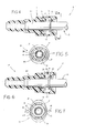
- Figure 1, is a side plan view of the preferred embodiment of a squeeze-to-release quick connector;
- Figure 2, is an end view of the connector of Figure 1 on an enlarged scale;
- Figure 3, is a cross-sectional view taken on line III-III of Figure 1 on an enlarged scale;
- Figure 4, is a fragmentary longitudinal cross-sectional view of the embodiment of Figure 1 in which the connector is coupled with a mating male tube end;
- Figure 5, is a cross-sectional view taken on line V-V of Figure 4;
- Figures 6 and 7, correspond to Figures 4 and 5, respectively, but with the connector in a release position; and
- Figure 8, is a cross-sectional view taken on line VIII-VIII of Figure 3.
- Referring to the drawing Figures, a connector assembly, designated 10, embodying the present invention comprises a
female connector part 11 and amale connector part 12. The present invention will be described in detail hereinbelow adapted for incorporation within a system of tubular conduits for conducting fluid flow. However, it is contemplated that in the broadest sense, the present inventive connector could be readily adapted for other applications in view of the present specification. - Referring to Figures 1 through 3,
female connector part 11 is shown in detail.Female connector part 11 includes a generally cylindricalelongated body portion 13 having astepped bore 14 extending therethrough concentric with the body portion axis of elongation. As best seen in Figure 3, bore 14 exits rightwardly frombody portion 13 to define an opening 15 for receivingmale connector part 12.Body portion 13 transitions leftwardly into aconduit receiving adapter 16 which is generally tubular and through which bore 14 emerges leftwardly. The outer surface ofadapter 16 defines two or morecircumferential barbs 17 axially spaced therealong for engaging the inner diameter of a rubber or otherwise suitable conduit (not shown) in the usual manner. - A central segment 18 of
stepped bore 14 is dimensioned to form a slip fit with the nominal outside diameter ofmale connector part 12, as best shown in Figure 4. Aradial step 19 delineates central segment 18 with a left reduceddiameter segment 20 ofbore 14 extending throughadapter 16.Step 19 serves as an abutment surface for the leading edge ofmale connector part 12. A secondradial step 21 delineates central segment 18 and a right increased diameter segment 22 ofbore 14 which emerges rightwardly as opening 15. A radially inwardly directedcircumferential retaining rib 23 is formed within bore segment 22 axially interspaced betweenstep 21 and opening 15. The radially outwardmost portion of bore segment 22intermediate step 21 andrib 23 is designated as aseal receiving recess 24. In application, it is contemplated that an annular elastic seal, such as an O-ring (see Figure 4), would be disposed withinrecess 24 and retained in position byrib 23 for providing sealing engagement betweenbore 14 ofbody portion 13 and the outer diameter surface ofmale connector part 12. - An
annular retaining ring 25 is disposed concentrically about the axis of elongation ofbody portion 13 and is axially spaced rightwardly (as viewed in Figure 3) from opening 15. The degree of axial spacing between retainingring 25 and opening 15 is not deemed critical. The two need only by separated sufficiently to ensure thatring 25 can be manipulated without interference from the adjacent end ofbody portion 13. In the preferred embodiment, sufficient spacing is provided to accommodate an upset or flange ofmale connector part 12. Retainingring 25 is joined with the remainder ofconnector part 11 by two circumferentially opposed, generally parallel, axiallyelongated beam members Beam members ring 25 nearest opening 15. The remaining ends ofbeam members body portion 13 through intermediaterespective mounting bosses body portion 13. In the preferred embodiment, beam members have a pentagon-shaped cross-section as seen in Figures 2 and 8. Alternatively, rhombic, diamond, lozenge or similar cross-section profiles could be substituted. - Retaining
ring 25 has acentral opening 30 which has a characteristic diameter exceeding that of bore segment 22 for providing clearance formale connector part 12 as best viewed in Figures 4 through 7. Two circumferentially spaced detents extend radially inwardly from retainingring 25 withincentral opening 30. Each detent is angularly aligned with one of thebeam members 26, 27 (see Figure 2) and forms a radiallytapering ramp surface 32 on a side of eachdetent 31 facing away from opening 15 and a radiallytransverse abutment surface 33 on a side thereof facing opening 15.Detents 31 extend radially inwardly withincentral opening 30 such as to have a diametrical spacing therebetween which is greater than the diameter of bore segment 18 and slightly less than the diameter of bore segment 22 which, as viewed in Figure 3, is designatedD. Beam members ring 25 and mountingbosses bosses adapter 16, preferably axially coextensive withradial Step 21 ofbody portion 13. Such positioning provides a substantially rigid base for mountingbeam members ring 25, as will be described in detail hereinbelow without distortion of the open end ofbody portion 13. Furthermore, beam members are spaced radially outwardly of and generally parallel to (in the relaxed condition)body portion 13, and transition intobosses ring 25 through contoured tapers to avoid abrupt transitions which can create stress raisers. - As best seen in Figure 2, retaining
ring 25 is provided with a specific profile in the transverse plane to enhance its advantageous operation as described herein. Although described as generally annular in shape, retainingring 25 is preferably formed from upper andlower crescent portions web members crescent portions beam members Web members - The entire
female connector part 11 is preferably injection molded as a single homogeneous piece from suitable material such as Nylon 66 unfilled. Although many materials would be suitable for practicing the present invention, Nylon 66 has been found to be particularly advantageous in certain automotive applications. When the retainingring 25 is configured as described hereinabove, the portions thereofadjacent beam members web members connector assembly 10 can be released to enable uniaxial separation offemale connector part 11 andmale connector part 12 simply by grasping and squeezing together of grip surfaces 38 and 39. The crescent- shape configuration furthermore provides for greater travel ofweb members male connector part 12 to a release condition in which detents 31 are momentarily radially displaced outwardly to effect release of themale connector part 12. This configuration has been found to provide substantially easier release of theconnector assembly 10 as compared to prior art approaches involving release rings with uniform diameter and/or cross-sectional area. - Referring to Figures 4 and 5, female and
male connector parts male connector part 11 is a standard tube end with an upset or radially outwardly extending circumferential ridge formed therein adjacent and end which is matingly received withinbore 14 ofconnector part 11. Specifically,male connector part 12 includes aleading end 40 with a conventional upset 41 positioned slightly rearwardly therefrom. The leading edge of upset 41 comprises aramp surface 42 and the trailing edge thereof comprises anabutment surface 43. Prior to locking engagement illustrated in Figure 4,male connector part 12 engagesfemale part 11 wherebyramp surface 42 engagesramp surface 32 ofdetents 31 to momentarily distend retainingring 25 until upset 41 passes leftwardly ofabutment surface 33. Thereafter, the natural resiliency of the material of retainingring 25 causes it to reassume its original shape whereinafter removal ofmale part 12 is prevented by engagement of abutment surfaces 33 and 43. -
Connector assembly 10, is decoupled by the application of fingertip pressure radially inwardly at grippingsurfaces arrows 44 in Figure 7. As described hereinabove, the application of such pressure distends retainingring 25, causingdetents 31 to move radially outwardly as best seen in Figure 6. Once the innermost portion ofdetents 31 is positioned radially outwardly of upset 41,male connector part 12 can be decoupled fromfemale connector part 11 by axially withdrawing it in the usual manner. - A principle advantage of the present invention lies in the provision of
beam members ring 25 or the mountingboss ring 25 from the configuration shown in Figures 4 and 5 to the configuration shown in Figure 6 and 7 with the application of relatively little effort by the user while, simultaneously, maintaining structural rigidity both at the opening 15 as well as the circumferential positioning ofdetents 31. This represents a substantial improvement over known prior art designs which either are so rigid as to make release extremely difficult and require the exercise of large effort or, so flimsy that the detents tend to self- rotate in distortion and not release the male part. Such self-rotation can be envision by a slight rotation of eachdetent 31, causing a corner of eachabutment surface 33 to remain engaged withabutment surface 42 ofmale part 12. The propensity of such circumferential distortion is substantially reduced with the present design. Furthermore, many prior art designs tend to have large inherent stress risers, resulting in premature fracture failures. The provision of relativelylong beam members - A
circumferential skirt 45 extends axially outwardly fromdetents 31 to serve as a guide for leadingend 40 ofmale part 12 during the insertion process, as well as permitting use of a reduced overall wall thickness in retainingring 25 to further enhance ease of decoupling without degrading pull-apart strength. - It is to be understood that the invention has been described with reference to a specific preferred embodiment which provides the features and advantages previously discussed and that such embodiment is susceptible of modification as will be apparent to those skilled in the art. For example, any number of beam member configurations will be apparent in view of this specification. In the broadest sense definitionally, a beam member is deemed to be any structure that functions as a load disturbing beam subjected primarily to bending rather than tension and compression which is connected at one point to the body portion and at another point to the retaining ring. Accordingly, the foregoing is not to be construed in a limiting sense.
Claims (18)
Applications Claiming Priority (2)
| Application Number | Priority Date | Filing Date | Title |
|---|---|---|---|
| US07/753,758 US5213376A (en) | 1991-09-03 | 1991-09-03 | Squeeze-to-release quick connector |
| US753758 | 2001-01-02 |
Publications (3)
| Publication Number | Publication Date |
|---|---|
| EP0530485A2 true EP0530485A2 (en) | 1993-03-10 |
| EP0530485A3 EP0530485A3 (en) | 1993-04-21 |
| EP0530485B1 EP0530485B1 (en) | 1996-05-15 |
Family
ID=25032033
Family Applications (1)
| Application Number | Title | Priority Date | Filing Date |
|---|---|---|---|
| EP92112668A Expired - Lifetime EP0530485B1 (en) | 1991-09-03 | 1992-07-24 | Squeeze-to-release quick connector |
Country Status (4)
| Country | Link |
|---|---|
| US (1) | US5213376A (en) |
| EP (1) | EP0530485B1 (en) |
| DE (1) | DE69210719T2 (en) |
| ES (1) | ES2087361T3 (en) |
Cited By (10)
| Publication number | Priority date | Publication date | Assignee | Title |
|---|---|---|---|---|
| EP0679828A1 (en) * | 1994-04-28 | 1995-11-02 | Kaltenbach & Voigt Gmbh & Co. | Connector, especially for a pneumatic, hydraulic or electrical transmission link |
| EP0680736A1 (en) * | 1994-05-06 | 1995-11-08 | E.R. Squibb & Sons, Inc. | Ostomy coupling |
| CN1044034C (en) * | 1994-04-27 | 1999-07-07 | 樱护谟株式会社 | Coupling apparatus |
| EP0982525A1 (en) * | 1998-08-25 | 2000-03-01 | Nobel Plastiques | One-piece snap coupling |
| WO2002037014A1 (en) | 2000-11-03 | 2002-05-10 | Nobel Plastiques | Single-piece snap-on connection |
| FR2829554A1 (en) | 2001-09-13 | 2003-03-14 | Nobel Plastiques | Female plastic clip-on coupling for male adapter with collar e.g. for fluid circuit, has locking element in form of lever on flexible supports |
| EP0691501B2 (en) † | 1994-07-08 | 2004-03-24 | Voss Automotive GmbH | Plug-in connector for hoses and/or pipe conduits |
| FR2850155A1 (en) * | 2003-01-16 | 2004-07-23 | Cf Gomma Spa | Degassing channel connection device for heat conducting circuit, has connection unit with clenching unit to fix pipe on degassing channel, and connection unit is made up of thermoplastic and molded on pipe by casting |
| DE10156750B4 (en) * | 2000-11-22 | 2009-09-03 | Draeger Ltd., Blyth | Closing connection between breathing gas supply and breathing mask |
| FR2963078A1 (en) * | 2010-07-21 | 2012-01-27 | Delfingen Fr Anteuil Sa | Fluids transferring tube for tube and manifold assembly to receive manifold e.g. connector with maintain shoulder, has flexible wall and stop arranged in manner to allow passage of shoulder of manifold by flexion of flexible wall |
Families Citing this family (56)
| Publication number | Priority date | Publication date | Assignee | Title |
|---|---|---|---|---|
| US5277402A (en) * | 1991-10-08 | 1994-01-11 | Itt Corporation | Quick connect fluid coupling with check valve |
| IL105065A (en) * | 1992-03-28 | 1995-05-26 | Smiths Ind Public Ltd | Coupling |
| US5466017A (en) * | 1993-09-17 | 1995-11-14 | Itt Corporation | Squeeze-to-release quick connector |
| US5378025A (en) * | 1993-11-03 | 1995-01-03 | Itt Corporation | Quick connector with integral release member |
| DE4344665A1 (en) * | 1993-12-27 | 1995-06-29 | Raymond A & Cie | Protective cap for a detachable quick release coupling |
| FR2721088B1 (en) * | 1994-06-10 | 1997-09-12 | Bosch Gmbh Robert | Fuel line connection comprising a nozzle and a device for axially locking it in the connection hole. |
| WO1996008078A1 (en) * | 1994-09-02 | 1996-03-14 | Philips Electronics N.V. | Receiver with quadrature decimation stage, method of processing digital signals |
| US5537727A (en) * | 1994-09-28 | 1996-07-23 | Itt Corporation | Release tool for quick connector with integral release member |
| US5533761A (en) * | 1994-10-26 | 1996-07-09 | Itt Corporation | Quick connector release member |
| US5568946A (en) | 1994-12-14 | 1996-10-29 | Itt Corporation | Squeeze-to-release quick connector with snap-in retainer |
| US5951063A (en) * | 1995-06-07 | 1999-09-14 | Itt Manufacturing Enterprises, Inc. | Quick connector with snap-on retainer having enhanced engagement |
| US5742976A (en) * | 1995-12-18 | 1998-04-28 | Black & Decker Inc. | Holding device for an end of a hose in a vacuum apparatus |
| US5711553A (en) * | 1996-09-04 | 1998-01-27 | Stmc-Llc | Quick connect fluid coupling |
| US5873610A (en) * | 1996-12-19 | 1999-02-23 | Itt Automotive, Inc. | Female connector member for large tolerance male member endforms |
| US5897142A (en) * | 1996-12-19 | 1999-04-27 | Itt Automotive, Inc. | Push-to-release quick connector |
| US5863077A (en) * | 1996-12-20 | 1999-01-26 | Itt Automotive, Inc. | Quick connector with snap-on frangible retainer |
| US5823508A (en) * | 1996-12-20 | 1998-10-20 | Itt Automotive, Inc. | One piece quick connect |
| US6293596B1 (en) | 1999-01-06 | 2001-09-25 | Itt Manufacturing Enterprises, Inc. | Quick connector with after incident indicator clip |
| JP2000274579A (en) * | 1999-03-24 | 2000-10-03 | Nifco Inc | Tube |
| JP3771745B2 (en) * | 1999-04-15 | 2006-04-26 | 松下電器産業株式会社 | Sheet presser and punching device for drilling ceramic green sheets |
| JP3724360B2 (en) * | 1999-11-09 | 2005-12-07 | 東海ゴム工業株式会社 | connector |
| US6688654B2 (en) * | 2000-12-08 | 2004-02-10 | Newfrey Llc | One piece quick connector |
| US7108293B2 (en) * | 2000-12-15 | 2006-09-19 | Zodiac Pool Care, Inc. | Swivel connector for a pipeline |
| US6802491B1 (en) | 2002-04-30 | 2004-10-12 | Itt Manufacturing Enterprises, Inc. | Fluid shut off valve cartridge with quick connection |
| FR2845607B1 (en) * | 2002-10-10 | 2005-06-24 | Vygon | MEDICAL USE FLUID CONNECTOR AND APPLICATIONS THEREOF |
| US7413366B2 (en) * | 2003-12-09 | 2008-08-19 | Unger Marketing International, Llc | Connecting members and methods for connecting implements to extension poles |
| JP2006200738A (en) * | 2004-12-24 | 2006-08-03 | Tokai Rubber Ind Ltd | Fluid transporting tube |
| WO2008079828A2 (en) * | 2006-12-20 | 2008-07-03 | Onset Medical Corporation | Expandable trans-septal sheath |
| EP2245354B1 (en) * | 2008-01-28 | 2012-06-13 | Colder Products Company | Quick connect/disconnect coupling assemblies |
| US7954515B2 (en) * | 2008-08-15 | 2011-06-07 | Colder Products Company | Combination cap and plug assembly |
| US10441120B1 (en) | 2010-04-30 | 2019-10-15 | Unger Marketing International, Llc | Universal connecting members |
| DE102010035027A1 (en) | 2010-08-20 | 2012-02-23 | Voss Automotive Gmbh | Locking element for a connector and connector with such a locking element |
| PL3685877T3 (en) | 2011-06-03 | 2023-11-27 | Fisher & Paykel Healthcare Limited | Medical tubes comprising conductive filaments and methods of manufacture |
| US9700672B2 (en) | 2011-09-21 | 2017-07-11 | Bayer Healthcare Llc | Continuous multi-fluid pump device, drive and actuating system and method |
| CN108042896A (en) | 2012-03-15 | 2018-05-18 | 费雪派克医疗保健有限公司 | Breathing gas humidification system |
| JP6388574B2 (en) | 2012-04-27 | 2018-09-12 | フィッシャー アンド ペイケル ヘルスケア リミテッド | Usability characteristics of respiratory humidification system |
| EP4035716A1 (en) | 2012-11-14 | 2022-08-03 | Fisher & Paykel Healthcare Limited | Zone heating for respiratory circuits |
| PL2928533T3 (en) | 2012-12-04 | 2021-05-17 | Fisher & Paykel Healthcare Limited | Medical tubes and methods of manufacture |
| DE112014004197T5 (en) | 2013-09-13 | 2016-06-02 | Fisher & Paykel Healthcare Limited | Connections for humidification system |
| US11511069B2 (en) | 2013-09-13 | 2022-11-29 | Fisher & Paykel Healthcare Limited | Humidification system |
| WO2015060731A1 (en) | 2013-10-24 | 2015-04-30 | Fisher & Paykel Healthcare Limited | Delivery of respiratory gases |
| CN110947069A (en) | 2013-12-20 | 2020-04-03 | 费雪派克医疗保健有限公司 | Humidification system connection |
| US10449319B2 (en) | 2014-02-07 | 2019-10-22 | Fisher & Paykel Healthcare Limited | Respiratory humidification system |
| EP3501586B1 (en) | 2014-03-17 | 2021-02-17 | Fisher & Paykel Healthcare Limited | Medical tubes for respiratory systems |
| US11173272B2 (en) | 2014-05-02 | 2021-11-16 | Fisher & Paykel Healthcare Limited | Gas humidification arrangement |
| EP3142737B1 (en) | 2014-05-13 | 2020-07-08 | Fisher & Paykel Healthcare Limited | A port cap for a humidification apparatus and a humidification apparatus |
| US11324911B2 (en) | 2014-06-03 | 2022-05-10 | Fisher & Paykel Healthcare Limited | Flow mixers for respiratory therapy systems |
| US11278689B2 (en) | 2014-11-17 | 2022-03-22 | Fisher & Paykel Healthcare Limited | Humidification of respiratory gases |
| AU2016205275B2 (en) | 2015-01-09 | 2020-11-12 | Bayer Healthcare Llc | Multiple fluid delivery system with multi-use disposable set and features thereof |
| US10385999B2 (en) * | 2015-07-09 | 2019-08-20 | Terumo Cardiovascular Systems Corporation | Fluid coupling devices |
| TWI720015B (en) | 2015-09-09 | 2021-03-01 | 紐西蘭商費雪派克保健有限公司 | Zone heating for respiratory circuits |
| EP4063811A1 (en) | 2016-12-07 | 2022-09-28 | Fisher & Paykel Healthcare Limited | Seal/cover for use with a sensing arrangement of a medical device |
| US11311695B2 (en) | 2016-12-22 | 2022-04-26 | Fisher & Paykel Healthcare Limited | Medical tubes and methods of manufacture |
| KR20200142100A (en) * | 2018-05-08 | 2020-12-21 | 베이리스 메디컬 컴퍼니 아이엔씨. | Coupling mechanisms for devices |
| USD937411S1 (en) | 2019-08-30 | 2021-11-30 | Fisher & Paykel Healthcare Limited | Unit end connector |
| DE202020003252U1 (en) | 2020-07-29 | 2021-11-02 | Till Geier | Device for generating standing waves |
Citations (4)
| Publication number | Priority date | Publication date | Assignee | Title |
|---|---|---|---|---|
| US3990727A (en) * | 1976-01-26 | 1976-11-09 | Stephen Franics Gallagher | Quick detachable coupler |
| US4793639A (en) * | 1988-04-29 | 1988-12-27 | Chrysler Motors Corporation | Tube coupling mechanism |
| US4844512A (en) * | 1987-07-06 | 1989-07-04 | Ems-Inventa Ag | Freely rotatable snap-fit connector for pipes |
| GB2227064A (en) * | 1988-12-07 | 1990-07-18 | Inventa Ag | Snap-fit pipe connector |
Family Cites Families (2)
| Publication number | Priority date | Publication date | Assignee | Title |
|---|---|---|---|---|
| US3588149A (en) * | 1969-08-13 | 1971-06-28 | Amp Inc | Vacuum or pressure coupling devices |
| JPH0674875B2 (en) * | 1988-12-07 | 1994-09-21 | エムス − インヴエンタ・アクチエンゲゼルシヤフト | Quick disconnect joint |
-
1991
- 1991-09-03 US US07/753,758 patent/US5213376A/en not_active Expired - Lifetime
-
1992
- 1992-07-24 DE DE69210719T patent/DE69210719T2/en not_active Expired - Lifetime
- 1992-07-24 ES ES92112668T patent/ES2087361T3/en not_active Expired - Lifetime
- 1992-07-24 EP EP92112668A patent/EP0530485B1/en not_active Expired - Lifetime
Patent Citations (4)
| Publication number | Priority date | Publication date | Assignee | Title |
|---|---|---|---|---|
| US3990727A (en) * | 1976-01-26 | 1976-11-09 | Stephen Franics Gallagher | Quick detachable coupler |
| US4844512A (en) * | 1987-07-06 | 1989-07-04 | Ems-Inventa Ag | Freely rotatable snap-fit connector for pipes |
| US4793639A (en) * | 1988-04-29 | 1988-12-27 | Chrysler Motors Corporation | Tube coupling mechanism |
| GB2227064A (en) * | 1988-12-07 | 1990-07-18 | Inventa Ag | Snap-fit pipe connector |
Cited By (14)
| Publication number | Priority date | Publication date | Assignee | Title |
|---|---|---|---|---|
| CN1044034C (en) * | 1994-04-27 | 1999-07-07 | 樱护谟株式会社 | Coupling apparatus |
| EP0679828A1 (en) * | 1994-04-28 | 1995-11-02 | Kaltenbach & Voigt Gmbh & Co. | Connector, especially for a pneumatic, hydraulic or electrical transmission link |
| EP0680736A1 (en) * | 1994-05-06 | 1995-11-08 | E.R. Squibb & Sons, Inc. | Ostomy coupling |
| EP0691501B2 (en) † | 1994-07-08 | 2004-03-24 | Voss Automotive GmbH | Plug-in connector for hoses and/or pipe conduits |
| EP0982525A1 (en) * | 1998-08-25 | 2000-03-01 | Nobel Plastiques | One-piece snap coupling |
| FR2782772A1 (en) * | 1998-08-25 | 2000-03-03 | Nobel Plastiques | SINGLE-BODY SNAP-ON CONNECTOR |
| WO2002037014A1 (en) | 2000-11-03 | 2002-05-10 | Nobel Plastiques | Single-piece snap-on connection |
| FR2816390A1 (en) | 2000-11-03 | 2002-05-10 | Nobel Plastiques | SINGLE-BODY SNAP-ON CONNECTOR |
| DE10156750B4 (en) * | 2000-11-22 | 2009-09-03 | Draeger Ltd., Blyth | Closing connection between breathing gas supply and breathing mask |
| FR2829554A1 (en) | 2001-09-13 | 2003-03-14 | Nobel Plastiques | Female plastic clip-on coupling for male adapter with collar e.g. for fluid circuit, has locking element in form of lever on flexible supports |
| WO2003025449A1 (en) | 2001-09-13 | 2003-03-27 | Nobel Plastiques | Single-piece snap-on connection |
| US6916050B2 (en) | 2001-09-13 | 2005-07-12 | Nobel Plastiques | Single-piece snap-on connection |
| FR2850155A1 (en) * | 2003-01-16 | 2004-07-23 | Cf Gomma Spa | Degassing channel connection device for heat conducting circuit, has connection unit with clenching unit to fix pipe on degassing channel, and connection unit is made up of thermoplastic and molded on pipe by casting |
| FR2963078A1 (en) * | 2010-07-21 | 2012-01-27 | Delfingen Fr Anteuil Sa | Fluids transferring tube for tube and manifold assembly to receive manifold e.g. connector with maintain shoulder, has flexible wall and stop arranged in manner to allow passage of shoulder of manifold by flexion of flexible wall |
Also Published As
| Publication number | Publication date |
|---|---|
| US5213376A (en) | 1993-05-25 |
| EP0530485A3 (en) | 1993-04-21 |
| EP0530485B1 (en) | 1996-05-15 |
| ES2087361T3 (en) | 1996-07-16 |
| DE69210719D1 (en) | 1996-06-20 |
| DE69210719T2 (en) | 1996-10-31 |
Similar Documents
| Publication | Publication Date | Title |
|---|---|---|
| US5213376A (en) | Squeeze-to-release quick connector | |
| US5466017A (en) | Squeeze-to-release quick connector | |
| EP0796405B1 (en) | Squeeze-to-release quick connector with snap-in retainer | |
| US4991882A (en) | Fluid-tight connector | |
| EP0946841B1 (en) | Push-to-release quick connector | |
| US5468030A (en) | Tube clamp and coupling | |
| AU613067B2 (en) | Quick connect coupling | |
| US5181751A (en) | Quick connector | |
| US7866710B2 (en) | Two piece quick connect retainer | |
| CA1316961C (en) | Controlled leak path | |
| US4181329A (en) | Releasable tube coupling | |
| US5425557A (en) | Apparatus for and method of attaching hoses and tubes to a fitting | |
| US5193857A (en) | Connector | |
| EP0397942A1 (en) | Releasable quick connect coupling | |
| JPH0211993A (en) | Hose joint | |
| US5551732A (en) | Quick connector | |
| US6234544B1 (en) | Quick connector with confirmation feature | |
| US5171028A (en) | Snap and lock quick connector | |
| US5711553A (en) | Quick connect fluid coupling | |
| WO1998028566A1 (en) | One piece quick connector and integral retainer | |
| US5192094A (en) | Expansion pipe joint | |
| JP4032406B2 (en) | Pipe fitting | |
| CA2556467C (en) | Two piece quick connect retainer | |
| EP0974783A1 (en) | Retainer for a quick connector | |
| EP0661489A1 (en) | Strengthening member for a deformable tubular body |
Legal Events
| Date | Code | Title | Description |
|---|---|---|---|
| PUAI | Public reference made under article 153(3) epc to a published international application that has entered the european phase |
Free format text: ORIGINAL CODE: 0009012 |
|
| PUAL | Search report despatched |
Free format text: ORIGINAL CODE: 0009013 |
|
| 17P | Request for examination filed |
Effective date: 19920724 |
|
| AK | Designated contracting states |
Kind code of ref document: A2 Designated state(s): DE ES FR GB IT SE |
|
| AK | Designated contracting states |
Kind code of ref document: A3 Designated state(s): DE ES FR GB IT SE |
|
| 17Q | First examination report despatched |
Effective date: 19950105 |
|
| ITF | It: translation for a ep patent filed |
Owner name: DE DOMINICIS & MAYER S.R.L. |
|
| GRAH | Despatch of communication of intention to grant a patent |
Free format text: ORIGINAL CODE: EPIDOS IGRA |
|
| GRAA | (expected) grant |
Free format text: ORIGINAL CODE: 0009210 |
|
| AK | Designated contracting states |
Kind code of ref document: B1 Designated state(s): DE ES FR GB IT SE |
|
| REG | Reference to a national code |
Ref country code: ES Ref legal event code: BA2A Ref document number: 2087361 Country of ref document: ES Kind code of ref document: T3 |
|
| REF | Corresponds to: |
Ref document number: 69210719 Country of ref document: DE Date of ref document: 19960620 |
|
| ET | Fr: translation filed | ||
| REG | Reference to a national code |
Ref country code: ES Ref legal event code: FG2A Ref document number: 2087361 Country of ref document: ES Kind code of ref document: T3 |
|
| PLBE | No opposition filed within time limit |
Free format text: ORIGINAL CODE: 0009261 |
|
| STAA | Information on the status of an ep patent application or granted ep patent |
Free format text: STATUS: NO OPPOSITION FILED WITHIN TIME LIMIT |
|
| 26N | No opposition filed | ||
| REG | Reference to a national code |
Ref country code: GB Ref legal event code: IF02 |
|
| PGFP | Annual fee paid to national office [announced via postgrant information from national office to epo] |
Ref country code: FR Payment date: 20110727 Year of fee payment: 20 |
|
| PGFP | Annual fee paid to national office [announced via postgrant information from national office to epo] |
Ref country code: SE Payment date: 20110712 Year of fee payment: 20 Ref country code: DE Payment date: 20110720 Year of fee payment: 20 Ref country code: ES Payment date: 20110817 Year of fee payment: 20 Ref country code: GB Payment date: 20110720 Year of fee payment: 20 |
|
| PGFP | Annual fee paid to national office [announced via postgrant information from national office to epo] |
Ref country code: IT Payment date: 20110714 Year of fee payment: 20 |
|
| REG | Reference to a national code |
Ref country code: DE Ref legal event code: R071 Ref document number: 69210719 Country of ref document: DE |
|
| REG | Reference to a national code |
Ref country code: DE Ref legal event code: R071 Ref document number: 69210719 Country of ref document: DE |
|
| REG | Reference to a national code |
Ref country code: GB Ref legal event code: PE20 Expiry date: 20120723 |
|
| REG | Reference to a national code |
Ref country code: SE Ref legal event code: EUG |
|
| PG25 | Lapsed in a contracting state [announced via postgrant information from national office to epo] |
Ref country code: DE Free format text: LAPSE BECAUSE OF EXPIRATION OF PROTECTION Effective date: 20120725 Ref country code: GB Free format text: LAPSE BECAUSE OF EXPIRATION OF PROTECTION Effective date: 20120723 |
|
| REG | Reference to a national code |
Ref country code: ES Ref legal event code: FD2A Effective date: 20130722 |