EP0536675A2 - Shelf with cantilever brackets - Google Patents
Shelf with cantilever brackets Download PDFInfo
- Publication number
- EP0536675A2 EP0536675A2 EP92116979A EP92116979A EP0536675A2 EP 0536675 A2 EP0536675 A2 EP 0536675A2 EP 92116979 A EP92116979 A EP 92116979A EP 92116979 A EP92116979 A EP 92116979A EP 0536675 A2 EP0536675 A2 EP 0536675A2
- Authority
- EP
- European Patent Office
- Prior art keywords
- hammer head
- cantilever
- stand
- punched
- hammer
- Prior art date
- Legal status (The legal status is an assumption and is not a legal conclusion. Google has not performed a legal analysis and makes no representation as to the accuracy of the status listed.)
- Granted
Links
Images


Classifications
-
- A—HUMAN NECESSITIES
- A47—FURNITURE; DOMESTIC ARTICLES OR APPLIANCES; COFFEE MILLS; SPICE MILLS; SUCTION CLEANERS IN GENERAL
- A47B—TABLES; DESKS; OFFICE FURNITURE; CABINETS; DRAWERS; GENERAL DETAILS OF FURNITURE
- A47B57/00—Cabinets, racks or shelf units, characterised by features for adjusting shelves or partitions
- A47B57/30—Cabinets, racks or shelf units, characterised by features for adjusting shelves or partitions with means for adjusting the height of detachable shelf supports
- A47B57/40—Cabinets, racks or shelf units, characterised by features for adjusting shelves or partitions with means for adjusting the height of detachable shelf supports consisting of hooks coacting with openings
- A47B57/42—Cabinets, racks or shelf units, characterised by features for adjusting shelves or partitions with means for adjusting the height of detachable shelf supports consisting of hooks coacting with openings the shelf supports being cantilever brackets
Definitions
- the invention relates to a cantilever rack for long products such as boards, pipes, profiled iron and the like.
- footplates on the cantilever arms in particular designed as double-T profiles, and extending from them against the uprights and provided for hanging in punched holes provided on the stands and the stands are designed as T-profile stands or as double T-profile stands, in the flanges of which the punched-outs are arranged in pairs at the same height and one above the other.
- a cantilever rack of the same type is known from EP-B1-0 061 514, in which a footplate is fastened to the end of each cantilever arm and two hooks are arranged on each footplate as exclusive holding elements. Even if this known cantilever rack requires little assembly effort when assembling, converting or dismantling, it is perceived as a disadvantage that the cantilever arms are each in one Angle must be pivoted upwards to be able to remove the hooks from the punched holes in the stand. This can result in time-consuming work processes, especially for conversions.
- DE-U-77 11 112 shows a screwless, adjustable heavy-duty cantilever rack, in which the cantilever arms made of stamped and bent sheet metal are suspended from double-T stands.
- side flaps are provided in addition to hooks through punched holes in the stands arranged on the cantilever arms. These side flaps are a hindrance when loading the shelf with long goods and, of all things, reduce the capacity of the cantilever arms at the structurally most favorable stacking point, near the base plates.
- the invention has for its object to provide a cantilever rack that can be assembled and disassembled with as little effort as possible, which can be easily adapted to the spatial conditions of the installation location and the type of goods to be stored and is particularly suitable for heavy-duty loading, and that Possibility of limited adjustment of the angle of inclination of the cantilever arms.
- a cantilever rack of the type mentioned with the invention in that two foot-head screws are assigned as fastening means to each footplate in their upper region in pairs at the same height, the footplate is formed with holes for receiving the threaded ends of the hammer-head screws and in their the lower area is arranged in pairs at the same height with two support feet that can be inserted into a pair of punched-outs, the hammer-head screws with transverse hammer heads reaching behind the punched-out holes of the stand flanges, through which they are initially inserted with vertically positioned heads, after transverse position in the anchor position.
- the load-bearing capacity and thus the safety of the cantilever arms is advantageous in a simple manner significantly increased that the vertical load components are intercepted by the support feet passing through the recesses and thus the hammer head screws are only subjected to tension.
- the hammer head screws can be preassembled in the factory with the foot plates, but then they are not yet fixed non-rotatably, but are arranged in the foot plates with vertically positioned hammer heads and only partially attached nuts.
- the cantilever arm with the support feet is then inserted into a pair of recesses, the hammer head screws also initially protruding vertically through recesses lying above them.
- the hammer heads are then turned into the transverse position, which means that the cantilever is already firmly attached to the stand before the nuts attached to the threaded ends are fully tightened. This advantageously results in a much faster and easier assembly compared to all known screw connections, with considerably reduced workload and increased safety.
- a shoulder with a square cross section is formed on the central shaft area of the hammer head screw between the threaded end and a smooth shaft part carrying the hammer head, which shoulder is in a square recess or recess that is at the front area of each hole in the footplate is formed, is designed to engage and the Keep screw non-rotatable after use in the specified position of the hammer head. This measure also simplifies assembly and increases safety.
- the invention relates to the specially designed and extremely easy-to-assemble, secure and resilient connection between a flange (2) of the stand (1) and a cantilever (4), the fastening means of which in openings or punched-out areas (3) the flanges (2) can be inserted and locked.
- each footplate (7) is formed at its lower area in pairs at the same height with two support feet (8) which can be engaged in a pair of punched-outs (3).
- holes (9) are provided in pairs at the same height for receiving the threaded ends (10) of the hammer head screws (5).
- Fig. 1 From Fig. 1 the particular usefulness of the arrangement according to the invention can be seen, with load forces acting in the vertical direction being supported by the support feet (8) on the lower punching (3), so that the hammer head screws (5) when the cantilever arm (4) is loaded exclusively be loaded in the direction of pull.
- a drop forged part made of high-strength steel in tempered quality such a hammer head screw can transmit tensile stresses, for example, in the order of magnitude of several tons.
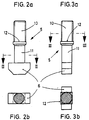
- FIGS. 2a and 3a show the hammer head screw (5) in two different views rotated by 90 ° .
- the cross section of the hammer head screw (5) is shown in section plane II-II according to FIG. 2a and in section plane III-III according to FIG. 3a in FIGS. 2b and 3b.
- This expedient embodiment of the hammer head screws (5) provides that a shoulder (12) with a square cross section is formed on the central shaft area of the hammer head screw (5) between the threaded end (10) and a smooth shaft part (11) carrying the hammer head (6), which is designed to engage in a square recess (13) which is formed on the front region of each bore (9) in the footplate (7) and holds the screw (5) in the non-rotatable position of the hammer head (6).
- the cantilever (4) is already in the workshop pre-assembled hammer head screws (5) can be inserted into the stand (1) without difficulty during assembly, it is provided that the head (6) of the hammer head screws (5) has an essentially rectangular cross section with rounded edges, the dimensions of which correspond to those of a punched-out ( 3) correspond with undersize.
- the head (5) can also deviate from the rectangular shape and, for example, be oval in cross section.
- the cantilever arm (4) then only needs to be inserted into the cutouts (3) with vertically positioned hammer heads (6) and with the support feet (8), after which at least one hammer head (6) is manually transversed, as shown in FIG.
- the rest of the assembly only consists in tightening the nuts (22), preferably with a predetermined torque.
- the nuts (22) are underlaid with a washer and, in some cases, are designed as self-locking nuts.
- An advantageous embodiment of the invention provides that the surface (21) of the footplate (7) facing the stand (1) has side webs (14) which merge with a wedge-shaped rise into a wedge-shaped foot region (15) of the plate (7). This ensures that the base plate (7) is approximately parallel to its surface (20) facing the cantilever arm (4) with the stand (1) and on the stand facing the stand Surface (21) to this at an acute angle (gamma) opening from bottom to top, with the foot region (15) being supported on the stand flange (2).
- this base plate (7) is particularly clear from the combination of FIGS. 4 and 5.
- this base plate (7) can be a cast part made of cast steel or nodular cast iron, so-called spheroidal cast iron, but it can also be produced as a drop-forged part.
- the cantilever arm (4) is welded to the smooth rear surface (20), with high-strength angular seams preferably being carried out on the upper, tensile area.
- the illustration further shows that the comparatively heavy-duty support foot (8) is forged or cast in one piece with the remaining material of the foot plate (7).
- Each support foot (8) protruding from the thickened foot region (15) of the footplate (7), has a support surface projecting approximately at right angles from it (18) and merges into the footplate (7) with a rounded nose section (19) at an obtuse angle (beta).
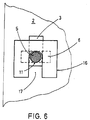
- FIG. 6 it is shown that the shim (16) is designed to be pluggable with a substantially rectangular cutout (17) over the shaft part (11) carrying the hammer head (6). This makes it extremely easy to store the washer (16).
- the invention is surprisingly both uncomplicated and extremely useful.
- the possibility of pre-assembly in the workshop makes it extremely easier to attach the cantilever arms (4) to the stands (1), while doing so with a minimum of work and thus also particularly secure.
- the same advantages also result when converting the cantilever rack, for example when changing the installation location or to adapt to special storage goods.
- the invention optimally fulfills the task set out above.
Abstract
Description
Die Erfindung betrifft ein Kragarm-Regal für Langgutprodukte wie Bretter, Rohre, Profileisen und dergl., mit Ständern und sich von diesen erstreckenden Kragarmen, wobei an den insbesondere als Doppel-T-Profile ausgebildeten Kragarmen Fußplatten und sich von diesen gegen die Ständer erstreckende und zum Einhängen in an den Ständern ausgebildete Ausstanzungen vorgesehene Befestigungsmittel angeordnet und die Ständer als T-Profilständer bzw. als Doppel-T-Profilständer ausgebildet sind, in deren Flanschen die Ausstanzungen paarweise im Abstand voneinander in gleicher Höhe sowie übereinander angeordnet sind.The invention relates to a cantilever rack for long products such as boards, pipes, profiled iron and the like., With stands and cantilevers extending from them, footplates on the cantilever arms, in particular designed as double-T profiles, and extending from them against the uprights and provided for hanging in punched holes provided on the stands and the stands are designed as T-profile stands or as double T-profile stands, in the flanges of which the punched-outs are arranged in pairs at the same height and one above the other.
Aus der EP-B1- 0 061 514 ist ein gattungsgleiches Kragarmregal bekannt, bei dem am Ende jedes Kragarmes eine Fußplatte befestigt ist und an jeder Fußplatte als ausschließliche Halteelemente zwei Haken angeordnet sind. Wenn auch dieses bekannte Kragarmregal einen geringen Montageaufwand beim Auf-, Um- oder Abbau erfordert, so wird doch als nachteilig empfunden, daß hierfür die Kragarme jeweils in einen Winkel schräg nach oben geschwenkt werden müssen, um die Haken aus den Ausstanzungen der Ständer herausnehmen zu können. Besonders bei Umbauten können sich hierbei zeitraubende Arbeitsabläufe ergeben.A cantilever rack of the same type is known from EP-B1-0 061 514, in which a footplate is fastened to the end of each cantilever arm and two hooks are arranged on each footplate as exclusive holding elements. Even if this known cantilever rack requires little assembly effort when assembling, converting or dismantling, it is perceived as a disadvantage that the cantilever arms are each in one Angle must be pivoted upwards to be able to remove the hooks from the punched holes in the stand. This can result in time-consuming work processes, especially for conversions.
Zur Vermeidung dieses Nachteils wurde mit der DE-A1-38 32 537 vorgeschlagen, daß in die Ausstanzungen die Haken horizontal einbringbar und mittels Sicherungselementen arretierbar sind. Bei besonders schweren Lasten sind diese Sicherungselemente auf Abscheren und Biegung stark beansprucht. Weiterhin sind die Haken an den Fußplatten angegossen, wodurch vergleichsweise hohe Fertigungskosten entstehen, außerdem sind die Haken Biege- und Zugbelastungen ausgesetzt.To avoid this disadvantage, it has been proposed with DE-A1-38 32 537 that the hooks can be inserted horizontally into the cutouts and locked by means of securing elements. In the case of particularly heavy loads, these securing elements are severely stressed on shearing off and bending. Furthermore, the hooks are cast on the foot plates, which results in comparatively high manufacturing costs, and the hooks are also exposed to bending and tensile loads.
Aus der US-A- 4 023 684 ist ein Regal mit Kragarmen zur Lagerung von Langgut bekannt. Die aus Doppel-T-Profilen bestehenden Kragarme sind mit Fußplatten versehen und an aus Doppel-T-Profilen bestehende Ständer angeschraubt. Die Schrauben sind bei schweren Belastungen sowohl auf Zug als auch auf Abscheren beansprucht und ergeben dadurch ein Sicherheitsrisiko. Weiterhin ist die Montagearbeit vergleichsweise aufwendig.From US-A-4 023 684 a shelf with cantilever arms for storing long goods is known. The cantilever arms, which consist of double-T profiles, are provided with base plates and screwed to stands made of double-T profiles. The screws are subjected to both tensile and shear loads under heavy loads and therefore pose a safety risk. Furthermore, the assembly work is comparatively complex.
Das DE-U- 77 11 112 zeigt ein schraubenlos verstellbares Schwerlast-Kragarmregal, bei welchem die aus gestanztem und gebogenem Blech bestehenden Kragarme an Doppel-T-Ständern eingehängt sind. Zur Sicherung der Kragarme sind zusätzlich zu Haken durch Ausstanzungen in den Ständern geführte Seitenlaschen an den Kragarmen angeordnet. Diese Seitenlaschen sind bei der Beladung des Regals mit Langgutprodukten hinderlich und verringern ausgerechnet an der statisch günstigsten Stapelstelle, in der Nahe der Fußplatten, die Aufnahmekapazität der Kragarme.DE-U-77 11 112 shows a screwless, adjustable heavy-duty cantilever rack, in which the cantilever arms made of stamped and bent sheet metal are suspended from double-T stands. To secure the cantilever arms, side flaps are provided in addition to hooks through punched holes in the stands arranged on the cantilever arms. These side flaps are a hindrance when loading the shelf with long goods and, of all things, reduce the capacity of the cantilever arms at the structurally most favorable stacking point, near the base plates.
Der Erfindung liegt die Aufgabe zugrunde, ein mit möglichst geringem Aufwand montierbares bzw. abbaubares Kragarmregal zu schaffen, das problemlos an die räumlichen Bedingungen des Aufstellortes und an die Art der zu lagernden Güter anpaßbar und für Schwerlast-Beladung besonders sicher geeignet ist, und das die Möglichkeit einer begrenzten Einstellung des Neigungswinkels der Kragarme bietet.The invention has for its object to provide a cantilever rack that can be assembled and disassembled with as little effort as possible, which can be easily adapted to the spatial conditions of the installation location and the type of goods to be stored and is particularly suitable for heavy-duty loading, and that Possibility of limited adjustment of the angle of inclination of the cantilever arms.
Diese Aufgabe wird bei einem Kragarmregal der eingangs genannten Art mit der Erfindung dadurch gelöst, daß als Befestigungsmittel jeder Fußplatte in ihrem oberen Bereich in paarweiser Anordnung auf gleicher Höhe zwei Hammerkopfschrauben zugeordnet sind, die Fußplatte mit Bohrungen zur Aufnahme der Gewindeenden der Hammerkopfschrauben ausgebildet und in ihrem unteren Bereich in paarweiser Anordnung auf gleicher Höhe mit zwei in ein Paar Ausstanzungen eingreifbaren Stützfüßen versehen ist, wobei die Hammerkopfschrauben mit quergestellten Hammerköpfen die Ausstanzungen der Ständerflansche, durch die sie mit zunächst vertikalgestellten Köpfen hindurchgesteckt sind, nach Querstellung in Ankerposition hintergreifen.This object is achieved with a cantilever rack of the type mentioned with the invention in that two foot-head screws are assigned as fastening means to each footplate in their upper region in pairs at the same height, the footplate is formed with holes for receiving the threaded ends of the hammer-head screws and in their the lower area is arranged in pairs at the same height with two support feet that can be inserted into a pair of punched-outs, the hammer-head screws with transverse hammer heads reaching behind the punched-out holes of the stand flanges, through which they are initially inserted with vertically positioned heads, after transverse position in the anchor position.
Mit Vorteil ist die Tragfähigkeit und damit die Sicherheit der Kragarme dadurch auf einfache Weise wesentlich erhöht, daß die vertikalen Lastkomponenten von den durch die Ausnehmungen hindurchtretenden Stützfüße abgefangen werden und damit die Hammerkopfschrauben nur noch auf Zug beansprucht sind.The load-bearing capacity and thus the safety of the cantilever arms is advantageous in a simple manner significantly increased that the vertical load components are intercepted by the support feet passing through the recesses and thus the hammer head screws are only subjected to tension.
Ein weiterer Vorteil für die Montage ergibt sich dadurch, daß die Hammerkopfschrauben bereits im Werk mit den Fußplatten vormontiert sein können, wobei sie dann aber noch nicht undrehbar festgelegt, sondern mit vertikalgestellten Hammerköpfen und nur teilweise angesetzten Muttern in den Fußplatten angeordnet sind. Zur Montage wird dann der Kragarm mit den Stützfüßen in ein Paar Ausnehmungen eingeführt, wobei die Hammerkopfschrauben mit zunächst vertikal gestellten Köpfen ebenfalls durch darüberliegende Ausnehmungen hindurchragen. Sodann werden die Hammerköpfe in Querstellung gedreht, womit der Kragarm bereits fest im Ständer hängt, bevor noch die an den Gewindeenden angesetzten Muttern vollends festgezogen sind. Hierdurch ergibt sich mit Vorteil eine gegenüber allen bekannten Schraubverbindungen wesentlich schnellere und leichtere Montage mit erheblich verringertem Arbeitsaufwand und erhöhter Sicherheit.Another advantage for the assembly results from the fact that the hammer head screws can be preassembled in the factory with the foot plates, but then they are not yet fixed non-rotatably, but are arranged in the foot plates with vertically positioned hammer heads and only partially attached nuts. For assembly, the cantilever arm with the support feet is then inserted into a pair of recesses, the hammer head screws also initially protruding vertically through recesses lying above them. The hammer heads are then turned into the transverse position, which means that the cantilever is already firmly attached to the stand before the nuts attached to the threaded ends are fully tightened. This advantageously results in a much faster and easier assembly compared to all known screw connections, with considerably reduced workload and increased safety.
Nach einer Ausgestaltung der Erfindung ist vorgesehen, daß am mittleren Schaftbereich der Hammerkopfschraube zwischen dem Gewindeende und einem glatten, den Hammerkopf tragenden Schaftteil eine Schulter mit quadratischem Querschnitt angeformt ist, die in eine quadratische Vertiefung bzw. Ausnehmung, die am vorderen Bereich jeder Bohrung der Fußplatte ausgeformt ist, eingreifbar ausgebildet ist und die Schraube nach Einsatz in die vorgegebene Stellung des Hammerkopfes undrehbar hält. Auch diese Maßnahme erleichtert die Montage und erhöht die Sicherheit.According to one embodiment of the invention, it is provided that a shoulder with a square cross section is formed on the central shaft area of the hammer head screw between the threaded end and a smooth shaft part carrying the hammer head, which shoulder is in a square recess or recess that is at the front area of each hole in the footplate is formed, is designed to engage and the Keep screw non-rotatable after use in the specified position of the hammer head. This measure also simplifies assembly and increases safety.
Zweckmäßige Ausgestaltungen der Erfindung sind entsprechend den Unteransprüchen vorgesehen. Weitere Einzelheiten, Merkmale und Vorteile der Erfindung ergaben sich aus der nachstehenden Erläuterung eines in den Zeichnungen schematisch dargestellten Ausführungsbeispieles.Appropriate embodiments of the invention are provided in accordance with the subclaims. Further details, features and advantages of the invention resulted from the following explanation of an embodiment shown schematically in the drawings.
Es zeigen:
Figur 1- eine Seitenansicht eines am Ständer angeordneten Kragarmes, z.T. im Schnitt,
- Figur 2a
- eine Ansicht einer Hammerkopfschraube,
- Figur 2b
- die Hammerkopfschraube im Schnitt einer Schnittebene II-II in Fig. 2a,
- Figur 3a
- die Hammerkopfschraube in Seitenansicht, d.h. gegenüber Fig. 2a um 90o gedreht,
- Figur 3b
- die Hammerkopfschaube im Schnitt einer Schnittebene III-III in Fig. 3a,
Figur 4- eine Ansicht der Fußplatte von der Ständerseite, Ansicht A in Fig. 5,
Figur 5- die Fußplatte in Seitenansicht,
Figur 6- eine Ansicht einer Unterlegplatte.
- Figure 1
- 2 shows a side view of a cantilever arm arranged on the stand, partly in section,
- Figure 2a
- a view of a hammer head screw,
- Figure 2b
- the hammer head screw in the section of a section plane II-II in Fig. 2a,
- Figure 3a
- the hammer head screw in side view, ie rotated by 90 o with respect to FIG. 2a,
- Figure 3b
- the hammer head screw in the section of a section plane III-III in Fig. 3a,
- Figure 4
- 4 shows a view of the footplate from the stand side, view A in FIG. 5,
- Figure 5
- the footplate in side view,
- Figure 6
- a view of a washer.
Ein Kragarm-Regal der eingangs genannten Art, wie es in der vorgenannten EP-B1- 0 061 514 sowie in der DE-A1- 38 32 537 jeweils dort in einer Figur 1 gezeigt und beschrieben ist, wird als bekannt vorausgesetzt, weshalb sich eine nochmalige Beschreibung erübrigt. Die Erfindung betrifft bei einem Kragarmregal dieser Art die in besonderer Weise ausgebildete und außerordentlich montagefreudige, sichere und belastbare Verbindung zwischen einem Flansch (2) des Ständers (1) und einem Kragarm (4), dessen Befestigungsmittel in öffnungen bzw. Ausstanzungen (3) in den Flanschen (2) einbringbar und arretierbar ausgestaltet sind.A cantilever rack of the type mentioned at the outset, as it is shown and described in FIG. 1 in the aforementioned EP-B1-0 061 514 and in DE-A1- 38 32 537, is assumed to be known, which is why a repeated description is unnecessary. In a cantilever rack of this type, the invention relates to the specially designed and extremely easy-to-assemble, secure and resilient connection between a flange (2) of the stand (1) and a cantilever (4), the fastening means of which in openings or punched-out areas (3) the flanges (2) can be inserted and locked.
Als Befestigungsmittel sind dabei an jeder Fußplatte (7) zwei Hammerkopfschrauben (5) vorgesehen und jede Fußplatte (7) ist an ihrem unteren Bereich in paarweiser Anordnung auf gleicher Höhe mit zwei in ein Paar Ausstanzungen (3) eingreifbaren Stützfüßen (8) ausgebildet. Im oberen Teil der Fußplatte (7) sind in paarweiser Anordnung auf gleicher Höhe Bohrungen (9) zur Aufnahme der Gewindeenden (10) der Hammerkopfschrauben (5) vorgesehen. Die Hammerkopfschrauben (5) hintergreifen nach Querstellung mit ihren quergestellten Hammerköpfen (6) die Ausstanzungen (3) der Ständerflansche (2), durch die sie bei der Montage mit zunächst vertikalgestellten Köpfen (6) hindurchgesteckt wurden.Two hammer head screws (5) are provided as fasteners on each footplate (7), and each footplate (7) is formed at its lower area in pairs at the same height with two support feet (8) which can be engaged in a pair of punched-outs (3). In the upper part of the base plate (7), holes (9) are provided in pairs at the same height for receiving the threaded ends (10) of the hammer head screws (5). After transverse positioning, the hammer head screws (5) with their transverse hammer heads (6) engage behind the punched-out areas (3) of the stand flanges (2), through which they were inserted during assembly with heads (6) initially placed vertically.
Aus Fig. 1 ist die besondere Zweckmäßigkeit der erfindungsgemäßen Anordnung ersichtlich, wobei in vertikaler Richtung wirkende Lastkräfte von den Stützfüßen (8) an der unteren Ausstanzung (3) abgestützt werden, so daß die Hammerkopfschrauben (5) bei Belastung des Kragarmes (4) ausschließlich in Zugrichtung belastet werden. Als Gesenkschmiedeteil aus hochfestem Stahl in vergüteter Qualität kann eine solche Hammerkopfschraube Zugbeanspruchungen beispielsweise in Größenordnungen von mehreren Tonnen übertragen.From Fig. 1 the particular usefulness of the arrangement according to the invention can be seen, with load forces acting in the vertical direction being supported by the support feet (8) on the lower punching (3), so that the hammer head screws (5) when the cantilever arm (4) is loaded exclusively be loaded in the direction of pull. As a drop forged part made of high-strength steel in tempered quality, such a hammer head screw can transmit tensile stresses, for example, in the order of magnitude of several tons.
In den Figuren 2a und 3a ist die Hammerkopfschraube (5) in zwei um 90o gedrehten unterschiedlichen Ansichten gezeigt. Der Querschnitt der Hammerkopfschraube (5) ist einmal in der Schnittebene II-II nach Fig. 2a und zum anderen in der Schnittebene III-III nach Fig. 3a in den Figuren 2b und 3b gezeigt. Diese zweckmäßige Ausgestaltung der Hammerkopfschrauben (5) sieht vor, daß am mittleren Schaftbereich der Hammerkopfschraube (5) zwischen Gewindeende (10) und einem glatten, den Hammerkopf (6) tragenden Schaftteil (11) eine Schulter (12) mit quadratischem Querschnitt angeformt ist, die in eine quadratische Vertiefung (13), die am vorderen Bereich jeder Bohrung (9) der Fußplatte (7) ausgeformt ist, eingreifbar ausgebildet ist und die Schraube (5) in der vorgegehenen Stellung des Hammerkopfes (6) undrehbar hält.FIGS. 2a and 3a show the hammer head screw (5) in two different views rotated by 90 ° . The cross section of the hammer head screw (5) is shown in section plane II-II according to FIG. 2a and in section plane III-III according to FIG. 3a in FIGS. 2b and 3b. This expedient embodiment of the hammer head screws (5) provides that a shoulder (12) with a square cross section is formed on the central shaft area of the hammer head screw (5) between the threaded end (10) and a smooth shaft part (11) carrying the hammer head (6), which is designed to engage in a square recess (13) which is formed on the front region of each bore (9) in the footplate (7) and holds the screw (5) in the non-rotatable position of the hammer head (6).
Damit der Kragarm (4) mit bereits werkstattseitig vormontierten Hammerkopfschrauben (5) ohne Schwierigkeiten bei der Montage in die Ständer (1) eingesetzt werden kann, ist vorgesehen, daß der Kopf (6) der Hammerkopfschrauben (5) einen im wesentlichen rechteckigen Querschnitt mit gerundeten Kanten aufweist, dessen Abmessungen denjenigen einer Ausstanzung (3) mit Untermaß entsprechen. Selbstverständlich kann der Kopf (5) auch von der Rechteckform abweichen und beispielsweise im Querschnitt oval ausgestaltet sein. Dabei braucht dann der Kragarm (4) nur mit vertikalgestellten Hammerköpfen (6) und mit den Stützfüßen (8) in die Ausstanzungen (3) eingesteckt zu werden, wonach zumindest ein Hammerkopf (6) von Hand quergesellt wird, wie dies in Fig. 1 gezeigt ist, so daß hierdurch bereits ein gefahrlos fester Sitz des Kragarmes (4) am Trägerfansch (2) gewährleistet ist und der Rest der Montage lediglich noch im Anziehen der Muttern (22) besteht, vorzugsweise mit vorgegebenem Drehmoment. Wie allgemein üblich und anerkannten Regeln der Technik entsprechend, sind die Muttern (22) mit einer Scheibe unterlegt und fallweise als selbstsichernde Muttern ausgebildet.So that the cantilever (4) is already in the workshop pre-assembled hammer head screws (5) can be inserted into the stand (1) without difficulty during assembly, it is provided that the head (6) of the hammer head screws (5) has an essentially rectangular cross section with rounded edges, the dimensions of which correspond to those of a punched-out ( 3) correspond with undersize. Of course, the head (5) can also deviate from the rectangular shape and, for example, be oval in cross section. The cantilever arm (4) then only needs to be inserted into the cutouts (3) with vertically positioned hammer heads (6) and with the support feet (8), after which at least one hammer head (6) is manually transversed, as shown in FIG. 1 is shown, so that this already ensures a secure, firm fit of the cantilever arm (4) on the carrier flange (2) and the rest of the assembly only consists in tightening the nuts (22), preferably with a predetermined torque. As is generally customary and in accordance with recognized rules of technology, the nuts (22) are underlaid with a washer and, in some cases, are designed as self-locking nuts.
Eine vorteilhafte Ausgestaltung der Erfindung sieht vor, daß die dem Ständer (1) zugewandte Fläche (21) der Fußplatte (7) Seitenstege (14) aufweist, die mit keilförmigem Anstieg in einen keilförmig verdickten Fußbereich (15) der Platte (7) übergehen. Damit wird erreicht, daß die Fußplatte (7) bei etwa parallelem Verlauf ihrer dem Kragarm (4) zugewandten Fläche (20) mit dem Ständer (1) und an der dem Ständer zugewandten Fläche (21) zu diesem in einem von unten nach oben zu sich öffnenden spitzten Winkel (gamma), mit dem Fußbereich (15) sich am Ständerflansch (2) abstützend, angeordnet ist. Dabei ergibt sich die Möglichkeit, durch Unterlegen einer oder mehrerer Unterlegplatten (16) unter den Hammerkopf (6) der Hammerkopfschraube (5) den Neigungwinkel (gamma) und damit den Kragarm (4) in einen veränderbaren Kragwinkel, beispielsweise kleiner als 90o, einzustellen (vgl. Fig. 1). Eine solche Möglichkeit ist fallweise sehr vorteilhaft für die Lagesicherheit eines Gutstapels und bei keiner der bekannten Ausführungen bisher gegeben. Durch die besondere Anordnung der Seitenstege (14) wird das Widerstandsmoment der Fußplatte (7) gegen Biegebeanspruchung erheblich vergrößert.An advantageous embodiment of the invention provides that the surface (21) of the footplate (7) facing the stand (1) has side webs (14) which merge with a wedge-shaped rise into a wedge-shaped foot region (15) of the plate (7). This ensures that the base plate (7) is approximately parallel to its surface (20) facing the cantilever arm (4) with the stand (1) and on the stand facing the stand Surface (21) to this at an acute angle (gamma) opening from bottom to top, with the foot region (15) being supported on the stand flange (2). It is possible to place the inclination angle (gamma) and thus the cantilever arm (4) in a variable cantilever angle, for example less than 90 o , by placing one or more washers (16) under the hammer head (6) of the hammer head screw (5) (see Fig. 1). In some cases, such a possibility is very advantageous for the positional security of a stack of goods and has not previously existed in any of the known designs. The special arrangement of the side webs (14) increases the section modulus of the footplate (7) against bending stress considerably.
Aus der Zusammenschau der Figuren 4 und 5 wird die Ausgestaltung der Fußplatte (7) besonders deutlich. Je nach Stückzahl und Anforderung kann diese Fußplatte (7) ein Gußformteil aus Stahlguß oder Kugelgraphitguß, sogenanntem Sphäroguß sein, sie kann aber auch als Gesenkschmiedeteil hergestellt werden. An der glatten Rückfläche (20) ist gemäß Darstellung in Fig. 1 der Kragarm (4) angeschweißt, wobei vorzugsweise am oberen, zugbelasteten Bereich hochbelastbare Winkelnähte zur Ausführung kommen. Die Darstellung zeigt weiter, daß der vergleichsweise hochbelastbare Stützfuß (8) einstückig mit dem übrigen Material der Fußplatte (7) angeschmiedet oder angegossen ist. Dabei weist jeder Stützfuß (8), aus dem verdickten Fußbereich (15) der Fußplatte (7) hervortretend, eine etwa rechtwinklig von diesem vorspringende Stützfläche (18) auf und geht mit abgerundeter Nasenpartie (19) unter einem stumpfen Winkel (beta) in die Fußplatte (7) über.The configuration of the base plate (7) is particularly clear from the combination of FIGS. 4 and 5. Depending on the number of pieces and requirements, this base plate (7) can be a cast part made of cast steel or nodular cast iron, so-called spheroidal cast iron, but it can also be produced as a drop-forged part. 1, the cantilever arm (4) is welded to the smooth rear surface (20), with high-strength angular seams preferably being carried out on the upper, tensile area. The illustration further shows that the comparatively heavy-duty support foot (8) is forged or cast in one piece with the remaining material of the foot plate (7). Each support foot (8), protruding from the thickened foot region (15) of the footplate (7), has a support surface projecting approximately at right angles from it (18) and merges into the footplate (7) with a rounded nose section (19) at an obtuse angle (beta).
In Figur 6 ist gezeigt, daß die Unterlegplatte (16) mit einem im wesentlichen rechteckigen Ausschnitt (17) über den den Hammerkopf (6) tragenden Schaftteil (11) steckbar U-förmig ausgebildet ist. Dadurch wird das Hinterlegen der Unterlegplatte (16) außerordentlich erleichtert.In FIG. 6 it is shown that the shim (16) is designed to be pluggable with a substantially rectangular cutout (17) over the shaft part (11) carrying the hammer head (6). This makes it extremely easy to store the washer (16).
Die Erfindung ist in überraschender Weise sowohl unkompliziert als auch äußerst zweckmäßig. Durch die Möglichkeit der Vormontage in der Werkstatt wird das Befestigen der Kragarme (4) an den Ständern (1) außerordentlich erleichtert, dabei mit einem Minimum an Arbeitsaufwand möglich und dadurch auch besonders sicher. Die gleichen Vorteile ergeben sich auch beim Umrüsten des Kragarm-Regales, beispielsweise bei Änderung des Aufstellorts oder zur Anpassung an besondere Lagergüter. Insofern erfüllt die Erfindung in optimaler Weise die eingangs gestellte Aufgabe.The invention is surprisingly both uncomplicated and extremely useful. The possibility of pre-assembly in the workshop makes it extremely easier to attach the cantilever arms (4) to the stands (1), while doing so with a minimum of work and thus also particularly secure. The same advantages also result when converting the cantilever rack, for example when changing the installation location or to adapt to special storage goods. In this respect, the invention optimally fulfills the task set out above.
Claims (8)
Applications Claiming Priority (2)
| Application Number | Priority Date | Filing Date | Title |
|---|---|---|---|
| DE4133288 | 1991-10-08 | ||
| DE4133288A DE4133288C2 (en) | 1991-10-08 | 1991-10-08 | Cantilever rack |
Publications (3)
| Publication Number | Publication Date |
|---|---|
| EP0536675A2 true EP0536675A2 (en) | 1993-04-14 |
| EP0536675A3 EP0536675A3 (en) | 1994-10-05 |
| EP0536675B1 EP0536675B1 (en) | 1996-11-27 |
Family
ID=6442254
Family Applications (1)
| Application Number | Title | Priority Date | Filing Date |
|---|---|---|---|
| EP92116979A Expired - Lifetime EP0536675B1 (en) | 1991-10-08 | 1992-10-05 | Shelf with cantilever brackets |
Country Status (6)
| Country | Link |
|---|---|
| EP (1) | EP0536675B1 (en) |
| AT (1) | ATE145530T1 (en) |
| DE (2) | DE4133288C2 (en) |
| DK (1) | DK0536675T3 (en) |
| ES (1) | ES2095381T3 (en) |
| GR (1) | GR3022280T3 (en) |
Families Citing this family (2)
| Publication number | Priority date | Publication date | Assignee | Title |
|---|---|---|---|---|
| DE29604799U1 (en) * | 1996-03-15 | 1996-06-05 | Fiedler Harald | Cantilever rack |
| DE19852235A1 (en) * | 1998-11-12 | 2000-05-18 | Volkswagen Ag | Fuel feed pump with storage container |
Citations (5)
| Publication number | Priority date | Publication date | Assignee | Title |
|---|---|---|---|---|
| US1760503A (en) * | 1929-09-03 | 1930-05-27 | Knape & Vogt Mfg Co | Bracket |
| US3114531A (en) * | 1959-12-04 | 1963-12-17 | Weber Albert | Shelf support |
| US4700916A (en) * | 1986-06-05 | 1987-10-20 | Hamilton Industries, Inc. | Cantilever arm assembly for modular furniture |
| EP0432372A1 (en) * | 1989-12-15 | 1991-06-19 | Joachim Lucht GmbH | Cantilever shelf |
| DE9107454U1 (en) * | 1991-06-18 | 1991-09-05 | Hoelscher, Ottokar, Dipl.-Ing., 5000 Koeln, De |
Family Cites Families (4)
| Publication number | Priority date | Publication date | Assignee | Title |
|---|---|---|---|---|
| FR10329E (en) * | 1906-08-01 | 1909-06-19 | Maurice Freud | Support arm for creased column shelves |
| US3512654A (en) * | 1968-05-09 | 1970-05-19 | Jarke Corp | Modular cantilever adjustable arm rack and joint assembly |
| CH602437A5 (en) * | 1975-06-16 | 1978-07-31 | Fehlbaum & Co | |
| DE3832537A1 (en) * | 1988-09-24 | 1990-03-29 | Hoelscher Ottokar | CANTILEVER SHELF |
-
1991
- 1991-10-08 DE DE4133288A patent/DE4133288C2/en not_active Expired - Fee Related
-
1992
- 1992-10-05 EP EP92116979A patent/EP0536675B1/en not_active Expired - Lifetime
- 1992-10-05 DE DE59207587T patent/DE59207587D1/en not_active Expired - Fee Related
- 1992-10-05 DK DK92116979.3T patent/DK0536675T3/da active
- 1992-10-05 ES ES92116979T patent/ES2095381T3/en not_active Expired - Lifetime
- 1992-10-05 AT AT92116979T patent/ATE145530T1/en not_active IP Right Cessation
-
1997
- 1997-01-15 GR GR970400054T patent/GR3022280T3/en unknown
Patent Citations (5)
| Publication number | Priority date | Publication date | Assignee | Title |
|---|---|---|---|---|
| US1760503A (en) * | 1929-09-03 | 1930-05-27 | Knape & Vogt Mfg Co | Bracket |
| US3114531A (en) * | 1959-12-04 | 1963-12-17 | Weber Albert | Shelf support |
| US4700916A (en) * | 1986-06-05 | 1987-10-20 | Hamilton Industries, Inc. | Cantilever arm assembly for modular furniture |
| EP0432372A1 (en) * | 1989-12-15 | 1991-06-19 | Joachim Lucht GmbH | Cantilever shelf |
| DE9107454U1 (en) * | 1991-06-18 | 1991-09-05 | Hoelscher, Ottokar, Dipl.-Ing., 5000 Koeln, De |
Also Published As
| Publication number | Publication date |
|---|---|
| DE59207587D1 (en) | 1997-01-09 |
| EP0536675B1 (en) | 1996-11-27 |
| EP0536675A3 (en) | 1994-10-05 |
| DE4133288C2 (en) | 1999-07-22 |
| DE4133288A1 (en) | 1993-04-15 |
| DK0536675T3 (en) | 1997-03-17 |
| GR3022280T3 (en) | 1997-04-30 |
| ATE145530T1 (en) | 1996-12-15 |
| ES2095381T3 (en) | 1997-02-16 |
Similar Documents
| Publication | Publication Date | Title |
|---|---|---|
| EP0926967B1 (en) | Cantilever type shelf | |
| EP1317631B1 (en) | Connecting part for mounting rails | |
| EP2430666B1 (en) | Support arrangement for solar modules | |
| DE2521426A1 (en) | BREAKING DEVICE FOR HOLDING A POST | |
| DE2746546A1 (en) | FACHWERKGEBAELK | |
| EP0596232B1 (en) | Supporting arrangement for a shuttering part placed at a right angle on a shuttering beam | |
| EP0611724A1 (en) | Guiding device for lifts | |
| DE102006039569A1 (en) | connecting element | |
| EP0519316B1 (en) | Cantilever shelf | |
| EP0536675B1 (en) | Shelf with cantilever brackets | |
| DE19514685C2 (en) | Arrangement of several pile shoes | |
| EP1207766B1 (en) | Cantilever type shelf | |
| DE3831517C2 (en) | ||
| CH561659A5 (en) | Lift running rail attachment - using a support element with bearing sections having adjustable spring loaded clamps | |
| DE3152360C2 (en) | ||
| DE202006007455U1 (en) | Fence element for constructing a fence comprises a horizontal locking bar having an outer profile rail and an inner profile rail which slide into each other along a longitudinal direction | |
| DE3438418A1 (en) | SUPPORT OR FRAME ARRANGEMENT FOR SHELVING SYSTEMS | |
| WO1989011813A1 (en) | Shelving system | |
| DE102010006560A1 (en) | Carrying device and formwork system | |
| DE2639987C2 (en) | Plug connection for skeleton constructions | |
| DE102021120323B4 (en) | Cantilever supported on one end for a cable support system | |
| EP0761904A1 (en) | Mounting system for panels | |
| EP0638694B1 (en) | Suspension anchor for T-profiles | |
| DE4314140C2 (en) | Horizontal bandage for absorbing the combustion chamber pressure for the outside walls of a steam generator | |
| DE102023116787A1 (en) | Suspension element for anchor plate of a side accident protection, anchor plate for side accident protection and system consisting of anchor plate and suspension element |
Legal Events
| Date | Code | Title | Description |
|---|---|---|---|
| PUAI | Public reference made under article 153(3) epc to a published international application that has entered the european phase |
Free format text: ORIGINAL CODE: 0009012 |
|
| PUAL | Search report despatched |
Free format text: ORIGINAL CODE: 0009013 |
|
| PUAF | Information related to the publication of a search report (a3 document) modified or deleted |
Free format text: ORIGINAL CODE: 0009199SEPU |
|
| 17P | Request for examination filed |
Effective date: 19921104 |
|
| AK | Designated contracting states |
Kind code of ref document: A2 Designated state(s): AT BE CH DE DK ES FR GB GR IE IT LI LU MC NL PT SE |
|
| AK | Designated contracting states |
Kind code of ref document: A3 Designated state(s): AT BE CH DE DK ES FR GB GR IE IT LI LU MC NL PT SE |
|
| RAP1 | Party data changed (applicant data changed or rights of an application transferred) |
Owner name: OHRA REGALANLAGEN GMBH |
|
| D17D | Deferred search report published (deleted) | ||
| PUAL | Search report despatched |
Free format text: ORIGINAL CODE: 0009013 |
|
| AK | Designated contracting states |
Kind code of ref document: A3 Designated state(s): AT BE CH DE DK ES FR GB GR IE IT LI LU MC NL PT SE |
|
| GRAG | Despatch of communication of intention to grant |
Free format text: ORIGINAL CODE: EPIDOS AGRA |
|
| GRAH | Despatch of communication of intention to grant a patent |
Free format text: ORIGINAL CODE: EPIDOS IGRA |
|
| 17Q | First examination report despatched |
Effective date: 19960318 |
|
| GRAH | Despatch of communication of intention to grant a patent |
Free format text: ORIGINAL CODE: EPIDOS IGRA |
|
| GRAA | (expected) grant |
Free format text: ORIGINAL CODE: 0009210 |
|
| AK | Designated contracting states |
Kind code of ref document: B1 Designated state(s): AT BE CH DE DK ES FR GB GR IE IT LI LU MC NL PT SE |
|
| REF | Corresponds to: |
Ref document number: 145530 Country of ref document: AT Date of ref document: 19961215 Kind code of ref document: T |
|
| ET | Fr: translation filed | ||
| GBT | Gb: translation of ep patent filed (gb section 77(6)(a)/1977) |
Effective date: 19961127 |
|
| REG | Reference to a national code |
Ref country code: IE Ref legal event code: FG4D Free format text: 70762 |
|
| REF | Corresponds to: |
Ref document number: 59207587 Country of ref document: DE Date of ref document: 19970109 |
|
| ITF | It: translation for a ep patent filed |
Owner name: STUDIO JAUMANN |
|
| REG | Reference to a national code |
Ref country code: ES Ref legal event code: FG2A Ref document number: 2095381 Country of ref document: ES Kind code of ref document: T3 |
|
| REG | Reference to a national code |
Ref country code: DK Ref legal event code: T3 |
|
| REG | Reference to a national code |
Ref country code: GR Ref legal event code: FG4A Free format text: 3022280 |
|
| REG | Reference to a national code |
Ref country code: PT Ref legal event code: SC4A Free format text: AVAILABILITY OF NATIONAL TRANSLATION Effective date: 19970218 |
|
| PLBE | No opposition filed within time limit |
Free format text: ORIGINAL CODE: 0009261 |
|
| STAA | Information on the status of an ep patent application or granted ep patent |
Free format text: STATUS: NO OPPOSITION FILED WITHIN TIME LIMIT |
|
| 26N | No opposition filed | ||
| REG | Reference to a national code |
Ref country code: GB Ref legal event code: IF02 |
|
| PGFP | Annual fee paid to national office [announced via postgrant information from national office to epo] |
Ref country code: GR Payment date: 20020822 Year of fee payment: 11 |
|
| PGFP | Annual fee paid to national office [announced via postgrant information from national office to epo] |
Ref country code: IE Payment date: 20020826 Year of fee payment: 11 |
|
| PGFP | Annual fee paid to national office [announced via postgrant information from national office to epo] |
Ref country code: PT Payment date: 20020904 Year of fee payment: 11 |
|
| PGFP | Annual fee paid to national office [announced via postgrant information from national office to epo] |
Ref country code: GB Payment date: 20020913 Year of fee payment: 11 |
|
| PGFP | Annual fee paid to national office [announced via postgrant information from national office to epo] |
Ref country code: NL Payment date: 20021017 Year of fee payment: 11 Ref country code: FR Payment date: 20021017 Year of fee payment: 11 |
|
| PGFP | Annual fee paid to national office [announced via postgrant information from national office to epo] |
Ref country code: MC Payment date: 20021021 Year of fee payment: 11 |
|
| PGFP | Annual fee paid to national office [announced via postgrant information from national office to epo] |
Ref country code: DK Payment date: 20021022 Year of fee payment: 11 Ref country code: AT Payment date: 20021022 Year of fee payment: 11 |
|
| PGFP | Annual fee paid to national office [announced via postgrant information from national office to epo] |
Ref country code: SE Payment date: 20021023 Year of fee payment: 11 Ref country code: LU Payment date: 20021023 Year of fee payment: 11 Ref country code: CH Payment date: 20021023 Year of fee payment: 11 Ref country code: BE Payment date: 20021023 Year of fee payment: 11 |
|
| PGFP | Annual fee paid to national office [announced via postgrant information from national office to epo] |
Ref country code: ES Payment date: 20021024 Year of fee payment: 11 |
|
| PGFP | Annual fee paid to national office [announced via postgrant information from national office to epo] |
Ref country code: DE Payment date: 20030812 Year of fee payment: 12 |
|
| PG25 | Lapsed in a contracting state [announced via postgrant information from national office to epo] |
Ref country code: LU Free format text: LAPSE BECAUSE OF NON-PAYMENT OF DUE FEES Effective date: 20031005 Ref country code: GB Free format text: LAPSE BECAUSE OF NON-PAYMENT OF DUE FEES Effective date: 20031005 Ref country code: AT Free format text: LAPSE BECAUSE OF NON-PAYMENT OF DUE FEES Effective date: 20031005 |
|
| PG25 | Lapsed in a contracting state [announced via postgrant information from national office to epo] |
Ref country code: SE Free format text: LAPSE BECAUSE OF NON-PAYMENT OF DUE FEES Effective date: 20031006 Ref country code: IE Free format text: LAPSE BECAUSE OF NON-PAYMENT OF DUE FEES Effective date: 20031006 Ref country code: ES Free format text: LAPSE BECAUSE OF NON-PAYMENT OF DUE FEES Effective date: 20031006 |
|
| PG25 | Lapsed in a contracting state [announced via postgrant information from national office to epo] |
Ref country code: MC Free format text: LAPSE BECAUSE OF NON-PAYMENT OF DUE FEES Effective date: 20031031 Ref country code: LI Free format text: LAPSE BECAUSE OF NON-PAYMENT OF DUE FEES Effective date: 20031031 Ref country code: CH Free format text: LAPSE BECAUSE OF NON-PAYMENT OF DUE FEES Effective date: 20031031 Ref country code: BE Free format text: LAPSE BECAUSE OF NON-PAYMENT OF DUE FEES Effective date: 20031031 |
|
| BERE | Be: lapsed |
Owner name: *OHRA REGALANLAGEN G.M.B.H. Effective date: 20031031 |
|
| PG25 | Lapsed in a contracting state [announced via postgrant information from national office to epo] |
Ref country code: PT Free format text: LAPSE BECAUSE OF NON-PAYMENT OF DUE FEES Effective date: 20040430 Ref country code: DK Free format text: LAPSE BECAUSE OF NON-PAYMENT OF DUE FEES Effective date: 20040430 |
|
| PG25 | Lapsed in a contracting state [announced via postgrant information from national office to epo] |
Ref country code: NL Free format text: LAPSE BECAUSE OF NON-PAYMENT OF DUE FEES Effective date: 20040501 |
|
| PG25 | Lapsed in a contracting state [announced via postgrant information from national office to epo] |
Ref country code: GR Free format text: LAPSE BECAUSE OF NON-PAYMENT OF DUE FEES Effective date: 20040504 |
|
| GBPC | Gb: european patent ceased through non-payment of renewal fee |
Effective date: 20031005 |
|
| EUG | Se: european patent has lapsed | ||
| REG | Reference to a national code |
Ref country code: DK Ref legal event code: EBP |
|
| REG | Reference to a national code |
Ref country code: CH Ref legal event code: PL |
|
| PG25 | Lapsed in a contracting state [announced via postgrant information from national office to epo] |
Ref country code: FR Free format text: LAPSE BECAUSE OF NON-PAYMENT OF DUE FEES Effective date: 20040630 |
|
| NLV4 | Nl: lapsed or anulled due to non-payment of the annual fee |
Effective date: 20040501 |
|
| REG | Reference to a national code |
Ref country code: IE Ref legal event code: MM4A |
|
| REG | Reference to a national code |
Ref country code: FR Ref legal event code: ST Ref country code: PT Ref legal event code: MM4A Free format text: LAPSE DUE TO NON-PAYMENT OF FEES Effective date: 20040430 |
|
| REG | Reference to a national code |
Ref country code: ES Ref legal event code: FD2A Effective date: 20031006 |
|
| PG25 | Lapsed in a contracting state [announced via postgrant information from national office to epo] |
Ref country code: DE Free format text: LAPSE BECAUSE OF NON-PAYMENT OF DUE FEES Effective date: 20050503 |
|
| PG25 | Lapsed in a contracting state [announced via postgrant information from national office to epo] |
Ref country code: IT Free format text: LAPSE BECAUSE OF NON-PAYMENT OF DUE FEES;WARNING: LAPSES OF ITALIAN PATENTS WITH EFFECTIVE DATE BEFORE 2007 MAY HAVE OCCURRED AT ANY TIME BEFORE 2007. THE CORRECT EFFECTIVE DATE MAY BE DIFFERENT FROM THE ONE RECORDED. Effective date: 20051005 |