EP0536901B2 - Display apparatus displaying operation menu - Google Patents
Display apparatus displaying operation menu Download PDFInfo
- Publication number
- EP0536901B2 EP0536901B2 EP92308240A EP92308240A EP0536901B2 EP 0536901 B2 EP0536901 B2 EP 0536901B2 EP 92308240 A EP92308240 A EP 92308240A EP 92308240 A EP92308240 A EP 92308240A EP 0536901 B2 EP0536901 B2 EP 0536901B2
- Authority
- EP
- European Patent Office
- Prior art keywords
- menu
- signal
- items
- sub
- picture
- Prior art date
- Legal status (The legal status is an assumption and is not a legal conclusion. Google has not performed a legal analysis and makes no representation as to the accuracy of the status listed.)
- Expired - Lifetime
Links
Images


Classifications
-
- H—ELECTRICITY
- H04—ELECTRIC COMMUNICATION TECHNIQUE
- H04N—PICTORIAL COMMUNICATION, e.g. TELEVISION
- H04N21/00—Selective content distribution, e.g. interactive television or video on demand [VOD]
- H04N21/40—Client devices specifically adapted for the reception of or interaction with content, e.g. set-top-box [STB]; Operations thereof
- H04N21/47—End-user applications
- H04N21/482—End-user interface for program selection
-
- H—ELECTRICITY
- H04—ELECTRIC COMMUNICATION TECHNIQUE
- H04N—PICTORIAL COMMUNICATION, e.g. TELEVISION
- H04N5/00—Details of television systems
- H04N5/44—Receiver circuitry for the reception of television signals according to analogue transmission standards
- H04N5/445—Receiver circuitry for the reception of television signals according to analogue transmission standards for displaying additional information
-
- H—ELECTRICITY
- H04—ELECTRIC COMMUNICATION TECHNIQUE
- H04N—PICTORIAL COMMUNICATION, e.g. TELEVISION
- H04N21/00—Selective content distribution, e.g. interactive television or video on demand [VOD]
- H04N21/40—Client devices specifically adapted for the reception of or interaction with content, e.g. set-top-box [STB]; Operations thereof
- H04N21/47—End-user applications
-
- H—ELECTRICITY
- H04—ELECTRIC COMMUNICATION TECHNIQUE
- H04N—PICTORIAL COMMUNICATION, e.g. TELEVISION
- H04N5/00—Details of television systems
- H04N5/76—Television signal recording
- H04N5/765—Interface circuits between an apparatus for recording and another apparatus
- H04N5/775—Interface circuits between an apparatus for recording and another apparatus between a recording apparatus and a television receiver
Definitions
- This invention relates generally to controlling a television receiver with a remote commander and, specifically, to controlling a television having the picture-in-picture feature.
- Recent television receivers have been equipped with various functions, such as the so-called picture-in-picture function and the ability to preset a TV channel program for viewing or recording.
- the picture-in-picture function the overall area of the screen is selected as a main screen, and a portion of this main screen is selected as a sub-screen on which pictures or images of another TV channel are displayed.
- Recent television receivers also include a built-in satellite broadcasting tuner to receive satellite broadcasting programs.
- a recent television receiver has been proposed in which, after a mechanical switch is switched on to place it into a standby state, the main power to the receiver can be switched on or off by a remote controller.
- the main power is switched on, each of the tuners for the VHF/UHF and the satellite broadcast is supplied with power and carries out its receiving and transmitting operations.
- the main power is switched off, the supply of the power to each of the tuners for VHF/UHF and for the satellite broadcast is deenergized, and the receiving and transmitting operations thereof are stopped.
- the television receiver described above also enables a desired reserved program to be received at a desired reserved time, and also can perform various settings such as a color adjustment setting, a volume adjustment setting, and the like by manipulation of a remote controller. Desired ones of the above items are displayed on the screen of the cathode-ray tube of the television receiver, and then parameters for the displayed items are set.
- menus are displayed on the sub-screen, for example, in order to simplify utilization of these functions by a user. That is to say, the attempt is made to improve the man-to-machine interface function.
- the setting items with regard to the plural functions provided by the television receiver are first displayed on the sub-screen.
- new setting items for example, the contents of operation and sequence of operation, are displayed.
- the user wants to register a recording reservation of a desired TV program for example the recording start and stop times and the channel number are set by the user.
- Another proposed television apparatus displays only selected items without other setting items, but it is nevertheless necessary for the receiver to prepare an image for displaying all items in order to display only selected items. This results in the drawback that a large amount of memory capacity is needed for displaying a menu.
- Simplification of operation of recent television receivers is also desired.
- One proposal for such simplification is to display a sequence of a menu on the screen, select the desired item by a moving cursor, and display the selected item for parameter setting.
- the cursor is frequently moved incorrectly, because of differences in the timing of transmission of operation data from the remote controller to the television and the timing of the scanning screen of the menu.
- the reserving operation is performed, if the user performs another operation, there is the possibility of mistake, for example, the undesired deletion of a parameter.
- JP-A-03/91385 discloses a television including means for displaying an operation menu, comprising display means for receiving a video signal displaying a picture and an operation menu, a video processing circuit for processing signals of the picture and the menu, user-operable operation means for controlling an operation indicated in the operation menu, display control means for controlling the appearance of marks and/or characters in the menu, and system control means for controlling the display control means and operation of the apparatus.
- GB-A-2155714 discloses a television system having a main menu, exemplified at 006 on Figure 4b, and a series of sub-menus, such as (i) the picture menu 013 in Figure 4d, (ii) the audio menu 026 in Figure 4g, (iii) the pre-sets menu at 033 in Figure 4j, (iv) the switch settings menu 041 on Figure 4k and (v) the features menu 051 on Figure 41. It is possible to visit the individual sub-menus from the main menu and to return to the main menu either on completion of adjustments or for operation on a different menu item of the main menu.
- pages 128 to 132 discloses a TV control system in which a horizontal strip menu is displayed on screen and sub-menus depend down from the items in the strip menu. Only currently possible menu items are displayed and the controller operates to ensure that nonsensical commands are not displayed at all.
- a television receiver can support many features without losing ease of operation, and provides a very easy-to-see-display.
- the menu is in common with many items of operations and only a small amount of memory capacity is needed. It then becomes easy to select an item by moving the cursor, and it is easy for the user to recognize which item is selected and operated correctly, and to prevent mistakes in erroneously changing parameters.
- the present invention is characterised by the features of claim 1.
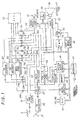
- Fig. 1 is a block diagram of a television receiver according to an embodiment of this invention including a VHF/UHF receiving section for receiving NTSC colortelevision signals and sound signals, and a receiving section for receiving signals from a broadcast satellite (BS) or from a communication satellite (CS).
- a control section controls and selects signals and a sound section reproduces the sound at a loudspeaker.
- the desired channel from the VHF/ UHF band is selected and the color video signal and audio sound signal are produced.
- the satellite broadcast receiver is connected to a parabola antenna 21 that receives the 12 GHz signal broadcast by the satellite, and the received signal is converted in frequency to a 1 GHZ signal using a BS converter 22.
- the converted signal is fed to a broadcast satellite tuner 23 that selects the desired channel, performs automatic gain control (AGC), IF amplitude, FM demodulation, de-emphasis, and reduction of an energy dispersal signal.
- AGC automatic gain control
- IF amplitude IF amplitude
- FM demodulation de-emphasis
- reduction of an energy dispersal signal The BS tuner 23 reproduces the video signal and audio signal modulated by pulse shift keying (PSK) and pulse code modulation (PCM).
- PSK pulse shift keying
- PCM pulse code modulation
- the BS tuner 23 When the A mode of BS broadcast is received, the BS tuner 23 reproduces four channels of PCM sound signals, and when the B mode is received, the BS tuner 23 reproduces two channels of PCM signals.
- a PSK demodulator 25 demodulates the signal and also detects the scrambling state of the signal, and a digital to analog (D/A) converter 26 converts the PCM digital audio signal from the PSK demodulator 25 to an analog sound signal.
- a level detector 27 detects the level of the received signal at the BS antenna 21 by detecting the output signal of the BS tuner 23 in the 8 MHz band.
- the tuned signal output from the BS tuner 23 is also fed to output terminals 28a, 28b, and 28c to external decoders.
- the BS tuner 23 is also connected to an input terminal 28d for receiving keyed AFC pulse from the MUSE signal.
- the BS receiving section including the BS tuner 23 selects the desired channel and supplies the signal to the output terminals when the received signal is scrambled or when it is a MUSE format signal. If the received signal is some other sort of signal, it does signal processing as if it was an NTSC signal and changes over the sound signal to two channels corresponding to the video signal or the sound signal to two channels not corresponding to the video signal, respectively.
- a MUSE down converter 51 can be connected for use in receiving a MUSE format signal (multiple sub-Nyquist encoding) to reproduce an HDTV signal.
- This HDTV signal is a TCI luminance and chrominance signal and a PCM sound signal.
- a Japanese Satellite Broadcast (JSB) decoder 52 can be connected for decoding a JSB scrambled broadcasting signal, and a communications satellite (CS) decoder can be connected for decoding a scrambled signal broadcast by a communications satellite.
- JSB Japanese Satellite Broadcast
- CS communications satellite
- the respective signals at output terminals 31a, 31b, 31c, 31d, 31e, and 31 f from the MUSE down converter 51, JSB decoder 52, and CS decoder 53, as well as outputs from the VHF/UHF tuner 12 and the video processing circuit 24 are selected for display by an audio-video (AV) switch 32.
- the AV switch 32 also selects audio signals from the VHF/UHF tuner 12, the D/A converter 26, the MUSE down converter 51, the JSB decoder 52, and the CS decoder 53.
- a video processing circuit 33 processes the color television signal selected by the AV switch 32 to an RGB signal for display.
- a picture-in-picture circuit 34 performs the necessary picture-in-picture processing in the well-known manner.
- An RGB switch switches the RGB signals from the picture-in-picture circuit 34 in response to a signal from the control section.
- a cathode-ray tube 36 displays the images of the selected signal, and an audio processing circuit 37 processes the audio to provide tone control and the like for reproduction over a loudspeaker 38.
- Output terminals 31g, 31h supply audio and video signals to an optional VTR 70 for recording.
- input terminals 31i, 31j receive video and audio signals from the optional VTR 70 for playback.
- the video processing circuit 33 supplies the video signal to the cathode-ray tube 36 for displaying and the audio processing circuit 37 supplies the audio signal to the loudspeaker 38.
- these circuits operate for displaying and reproducing the unscrambled video and audio signals from the JSB decoder 52, for example.
- These terminals supply the color television signal and the audio signal selected by the AV switch 32 to the VTR 70 and, if necessary, for displaying picture-in-picture, the menu of operation, and the contents of the many functions and settings.
- the system controller 41 controls the outputs based on the detected scrambled state of the PCM sound signal from the PSK demodulator 25 and on the state of the color television signal from video processing circuit 33.
- a memory 42 stores the control program and other operating settings set by the user.
- a BS microcomputer 43 controls the channel selection of the BS tuner 23.
- a digital-to-analog (D/A) converter 44 converts data from the system controller 41 to analog signals for controlling the volume of the reproduced sound.
- the display microcomputer 45 controls a menu display based on data from the system controller 41.
- a receiver 47 receives infrared radiation control signals from the remote controller 60.
- the system controller 41, the video processing circuit 33, the picture-in-picture circuit 34, the audio processing circuit 37, and the memory 42 are connected to each other by an I 2 C bus.
- an antenna 11 receives a VHF/UHF television signal and supplies it to the tuner 12.
- Tuner 12 is used to select the desired channel in response to a control signal from a controller 41 formed of a microcomputer that includes a video RAM, a ROM, and an additional RAM, all of which are internal.
- the controller 41 supplies control signals based on channel information signals supplied from a control panel 18 and from a remote controller 420 through a receiver 419.
- the controller 41 also memorizes parameters set by the user in a ROM 417 and performs many other operations synchronized by an oscillation signal from an oscillator 416a.
- the tuner 12 changes the frequency of the television signal to the IF signal frequencies, 58.75 MHz in the video and 54.25 MHz in the audio, respectively. These IF signals are amplified, detected, auto-gain controlled, and then supplied to the AV switch 32.
- the AV switch 32 supplies video and audio signals from an input terminal group 31, the tuner 12, and a BS receiver 422 to the video processing circuit 33 and to the audio processing circuit 37 under control of a signal from the controller 41.
- the VTR 70 is connected to the input terminal group 31 and to the output terminal group 31' for both video and audio signals.
- the video processing circuit 33 separates the chrominance signal from the composite video signal and generates a color difference signal. The video processing circuit 33 then generates RGB signals and supplies these signals to the cathode-ray tube 36. The video processing circuit 33 also generates deflection signals for vertical and horizontal deflection fed to vertical and horizontal deflection coils not forming a part of the present invention. The video processing circuit 33 also supplies the RGB signals for displaying control characters on the cathode-ray tube 36 under the control of the controller 41. An audio processing circuit 37 processes the audio signals and supplies them to the loudspeaker 38.
- the BS receiver 422 receives the satellite broadcast signal, for example, a 12 GHz signal, through a parabola antenna 21.
- the BS receiver 422 receives the FM TV signal and changes the frequency to the 1 GHz intermediate frequency (IF).
- the BS tuner 23 selects the band of the IF signal in response to control signals from the controller 41 as determined by the control panel 418 or the remote controller 420 and FM demodulates and supplies the demodulated signal to a video processing circuit 24 and to an audio processing circuit 25, respectively.
- Video processing circuit 24 processes the FM video signal and supplies a demodulated signal to the AV switch 32.
- the audio processing circuit 25 demodulates and converts to analog the 4-phase DPSK audio signal and feeds the processed audio signal to the AV selector switch 32.
- a power supply 421 energizes the main portion 410 of the television receiver and the BS receiver section 422.
- the power supply 421 is connected by a plug 424 to a source of AC power. This power supply 421 supplies power to the system.
- a switch 415 connected to the microcomputer 41 When a switch 415 connected to the microcomputer 41 is operated the microcomputer 41 is energized by power converted by a transformer 425 and placed in stand-by. In the case of watching TV or recording signals by a VTR, the user operates switches on the control panel 418 or on a remote controller 420.
- an infra-red signal is received through receiving unit 419 and fed to the microcomputer 41 to control the power supply 421.
- the AV selector switch 32 selects an input signal from the tuner 12, the BS tuner 23, or from the input terminal group 31 under control of the microcomputer 41.
- Each stroke of the change input key 420b sequentially changes the outputs of the video and audio on the cathode-ray tube 36 and the speaker 38.
- channel changing key 420c if the + key is pushed then the channel number increases and if the - key is pushed then the channel number is decreased.
- the channel number signal is also supplied to the microcomputer 41.
- Tuner 12 and BS tuner 23 select the channel and the desired image signal is displayed on the screen of the cathode-ray tube 36 by using the channel changing key 420c.
- the volume key 420d When operating the volume key 420d, if the + key is pushed then the sound volume increases and if the - key is pushed then the sound volume decreases.
- menu key 420e By pushing the menu key 420e, menu data is written into the video RAM in the microcomputer 41 and this data is read out and supplied to the cathode-ray tube 36 through video processing circuit 33 as RGB signals, and the menu is displayed. This data in the video RAM is read from a ROM that is also a part of the microcomputer 41.
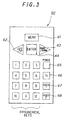
- Fig. 3 shows the configuration of the keys of the remote commander 60 shown in Fig. 1.
- Menu switch 61 displays the menu on the sub-screen of the cathode-ray tube 36.
- Cursor switches 62, 63 move the cursor left to right or top to bottom on the screen for selecting one of the items of the menu.
- Decision switch 64 selects the item indicated by the cursor.
- Power switch 65 operates the power supply of the television set.
- Input changing switches 66, 67, 68 select the input source for display.
- Numerical keys 69 change the channel numbers.
- the remote controller 60 selects a channel desired by the user and selects a color television signal from the video processing circuit 24 by operating the AV switch 32, and displays the image on the cathode-ray tube 36.
- the remote controller selects a sound signal from the D/A converter 26 by operating the AV switch 32 and outputs the sound through speaker 38. For example, in mode A, the television sound or an independent sound is selected and in mode B it selects the television sound.
- the received video signal is supplied to the JSB decoder 52 if the PCM sound channel is determined to be scrambled.
- the signal decoded by the JSB decoder 52 is then fed through the AV selection switch 32 and displayed on the cathode-ray tube 36 and the sound is reproduced by the speaker 38.
- the received signal is not scrambled it is supplied directly to the CRT and the speaker and not through the JSB decoder 52.
- control section controls the power supply to interrupt power to the video processing circuit 33 and the cathode-ray tube 36, and to provide power to the BS converter 22, the BS tuner 23, the PSK demodulator 25, the D/A converter 26, the audio processing circuit 37, and the system controller 41.
- the control section selects the predetermined BS channel, and outputs color video signal and sound signal to the VCR 70 through the output terminals 31g, 31h respectively and inhibits channel selection if the user subsequently tries to change the channel, for example, by operating the remote controller 60.
- the control section controls the display microcomputer 45 for displaying a sequence for recording a BS signal, for example, in the sub-screen. If the user operates the remote controller 60 to perform the picture-in-picture mode, the control section controls the AV switch 32, and the picture-in-picture circuit 34 for displaying the BS program on the main screen and a VHF/UHF TV program in the sub-screen, for example.
- the system controller 41 receives the channel number signal from the remote controller 60, controls the VHF/ UHF tuner 12 to select the set channel, and controls switches 32a, 32c for selecting the video and audio signals from the tuner 12, respectively.
- the video processing circuit 33 supplies the RGB signal converted from the color video signal fed by switch 32a to the cathode-ray tube 36.
- the audio processing circuit 37 supplies the audio signal to the speaker 38 with suitable processing, such as tone control. Thus, the user can watch the desired program on the VHF/UHF band.
- the system controller 41 supplies channel number data to the display microcomputer 45 through the I 2 C bus.
- the display microcomputer 45 supplies an RGB signal, for displaying the channel number at the upper-right edge on the screen, for example, to the video processing circuit 33 through the RGB switch 35.
- the video processing circuit 33 superimposes the RGB channel number onto the image of the broadcast program of the VHF/UHF band.
- the system controller 41 receives a control signal from the remote controller 60. controls the BS tuner 23 to select the BS channel, and detects whether the received program is an NTSC or hi-vision (HDTV) signal based on the state of synchronization of the PCM sound signal from the PSK demodulator 25 or based on the signal level at the level detection circuit 27. If an NTSC signal is detected, the system controller 41 controls the AV switch 32 to select the signal from the video processing circuit 24 and the signal from the D/A converter 26. If a hi-vision signal is detected, the system controller 41 controls the AV switch 32 to select the signal from the MUSE down converter 51.
- NTSC NTSC
- HDTV hi-vision
- the analog sound signal is converted to a PCM signal and modulated by PSK, and then frequency division multiplexed.
- the sound signal is converted to special differential PCM signal and TCI modulated in the period of the vertical synchronization signal.
- the system controller 41 detects that the signal is an NTSC signal if the received level at the level detection circuit 27 is high and it detects the synchronization signal of the PCM sound signal. It is decided that the received signal is a hi-vision signal if the received level is high and the synchronization is unlocked. Detection of a normal signal or hi-vision signal is also made based on the presence of a keyed AFC pulse supplied by MUSE down converter 51 to the BS tuner 23 through the input terminal 28d.
- the selected color video signal is supplied to the video processing circuit 33, and the selected audio signal is supplied to the audio processing circuit 37, so that the user can watch each channel by only the desired setting channel in spite of the kind of BS program mode.
- the system controller 41 receives a control signal corresponding to the picture-in-picture operation from the remote controller 60, controls the VHF/UHF tuner 12 for selecting the set channel, and controls the switch 32b for selecting the color video signal from the VHF/UHF tuner 12.
- the selected color video signal is supplied to the picture-in-picture circuit and converted to the RGB signal and supplied as a signal for the sub-screen to the video processing circuit 33 through the RGB switch 35. In this way, the user can watch a BS program on the main screen and a VHF/UHF program on the sub screen.
- the system controller 41 detects the scrambled state of the program based on a state of the PCM sound signal from PSK demodulator 25 and selects color video signal from the video processing circuit 24 and sound signal from the D/A converter 26, if the program is not scrambled.
- the program selects the color video and audio signal from the JSB decoder 52.
- the user wants to listen to the sound of the independent sound program, if the sound signal of the television is scrambled, it selects the independent sound signal from the JSB decoder 52, and if the sound signal of the television is not scrambled, it selects the independent sound signal from the D/A converter 26.
- the number of combinations of scrambled and not scrambled programs is four, because there are scrambled and not scrambled states in the television sound signal (the same as video signal), and there are scrambled and not scrambled states in the independent sound signal.
- the system controller 41 performs control based on the scrambled state of the television sound signal, and the user can watch both scrambled and non-scrambled programs without manually changing the mode.
- the system controller 41 performs control based on the scrambled state of the television sound signal and the independent should signal, and the user can listen in each case without manually changing the mode.
- the signal path is not through the JSB decoder 52, so the sound quality is not damaged by passing through many circuits.
- the decision as to whether the program is scrambled or not is based on the 12th bit of a group of control bits of the PCM sound signal that shows the state of scramble of the video signal.
- the system controller 41 receives the control signal from the remote controller 60, controls the BS tuner 23 to select the set channel, and detects whether it is scrambled or not based on the state of the PCM sound signal from the PSK demodulator 25. If the not scrambled state is detected, the AV switch 32 is controlled to select a sound signal from the D/A converter 26. On the contrary, if a scrambled signal is detected, the AV switch 32 is controlled to select the sound signal output from the CS decoder 53.
- the sound signal of a nonscrambled program is converted to PCM signal and PSK duplex frequency modulated, and the sound signal of a scrambled program is first scrambled, PCM converted, and then PSK duplex modulated.
- the system controller 41 detects the scrambled or non-scrambled states based on the 8th bit of a range of bits from the PSK demodulator 25.
- the selected sound signal is supplied to the audio processing circuit 37, and the user can listen to the desired program without noticing whether the program is scrambled or not.
- the mode conversion of a scrambled or nonscrambled signal is not only enabled automatically as described but also permits manual selection using the remote controller 60.
- the system controller 41 receives a control signal for displaying the main menu relating to each functional setting, and supplies corresponding data to the display microcomputer 45 for displaying the main menu.
- the characters used for displaying the main menu can be stored in the memory 42 and output onto the I 2 C bus.
- the display microcomputer 45 displays the main menu on the sub-screen 36b, which is a part of the main screen 36a of the face of the cathode-ray tube 36 shown in Fig. 4b, based on this data from memory 42.
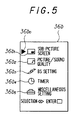
- Fig. 5 shows the main menu display including a display setting parameter 36b 1 of the sub screen in the picture-in-picture operation, a parameter 36b 2 for setting picture and sound qualities, a parameter 36b 3 for changing over the sound in the BS receiving mode, a parameter 36b 4 for setting the recording reservation, a parameter 36b 5 for setting the change-over of a bilingual sound mode, and a cursor 36b 0 .
- the display microcomputer 45 supplies an RGB signal for displaying the setting parameters and cursor to the video processing circuit 33 through the RGB switch 35.
- the video processing circuit 33 converts the color video signal at the AV switch 32 to the RGB signal, switches this RGB signal and the RGB signal from the RGB switch 35, displays the picture based on the signal from the AV switch 32a on the main screen 36a and displays the picture based on the RGB signal from the RGB switch 35 on the sub screen 36b, as shown in Fig. 4b.
- the user can move the cursor 36b 0 by pushing cursor switches 62, 63 of the remote controller 60 while watching the displayed menu. If the user pushes the enter switch 64, the setting parameter pointed to by the cursor 36b 0 is selected, and a new menu is displayed corresponding to the selected parameter.
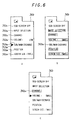
- the sub-screen menu is displayed on sub-screen 36c and as shown in Fig. 6a includes menu item 36b 11 for returning sub-screen display to the main menu, item 36b 12 for setting the source of the display on sub-screen 36c, item 36b 13 for setting the source channel, item 36b 14 for setting the sound volume corresponding to the picture in sub-screen 36c at the earphone output terminal, item 36b 15 for swapping the pictures in the main screen 36a and the sub-screen 36c, item 36b 16 for setting the position of the sub-screen 36c on the main screen 36a, item 36b 17 for setting the size of the sub-screen 36c, and a cursor 36b 10 .
- the user can set new parameters of the sub screen 36c, while confirming the displayed picture on the sub-screen 36c.
- the system controller 41 swaps the images of the main screen 36a and the sub-screen 36c, controls the AV switch 32, and stores setting parameter in the memory 42.
- the system controller 41 dims all other items being displayed except the selected setting parameter. This is the so-called half-tone and in the example of Fig. 6b all items except item 36b 15 are shown dimmed by the dotted background.
- the data for dimming is sent by controller 41 to the display microcomputer 45 by the I 2 C bus.
- the display microcomputer 45 controls the reduced RGB signal levels of all items except the swap item 36b 15 to the video processing circuit 33 through the RGB switch 35.
- the circuit for varying the output level of the display microcomputer 45 comprises resistors for DC bias 81R, 82R, resistors for matching output impedance 83R, 84R, and a resistor for varying the output level 85R.
- Resistors 81R, 82R are connected in series between a power source and ground.
- Resistors 83R, 84R are connected in series between the output of the red (R) signal of the display microcomputer 45 and an output terminal 86R.
- Resistor 85R is connected to a point between a signal output I of the display microcomputer 45 and output terminal 86R. When the dimmer mode is generated, the display microcomputer 45 shifts the level of signal I to low.
- the level of that signal I is high or open circuited.
- the level of the R signal supplied to the RGB switch 35 through the output terminal 86R is reduced.
- the blue (B) and green (G) signals are controlled the same as the R signal, and level controlled RGB signals are supplied to the video processing circuit 33. After that all items except the swap item 36b 15 , for example, are dimmed, and the user can confirm the selected setting item easily.
- FIG. 8 Another menu is shown in Fig. 8 and will be described in connection with the television receiver of Fig. 2.
- the menu key 420e of the remote controller 420 When the user pushes the menu key 420e of the remote controller 420, the menu picture shown in Fig. 8 is displayed on the screen of the cathode-ray tube 36.
- the selection and decision roller 420f is used to move a cursor m3 when the menu is displayed on the screen of the cathode-ray tube 36. By rotating this roller 420f in one direction or the other, the cursor m3 is moved at the left of symbols ml having legends m2, and the selected item m2 is entered by depressing roller 420f and closing internal switch contacts.
- a so-called nth layer of hierarchy is displayed on the screen, as shown in Fig. 9.
- the desired item m2 is selected by pushing 420f the desired item m2 is entered based on the menu of Fig. 8.
- a sub-menu is then displayed and utilized and following that the menu in Fig. 9 is displayed.
- Parameter data of each item set by this process are memorized at ROM 417, which may be embodied as an EEPROM. If the user wants to stop the display the menu key 420e is pushed, and the system controller 41 stops sending menu data to the display. By providing control of the menu display in this way the selected item of the menu may also be displayed as a different color.
- Fig. 10 shows an operational flow chart of the method for moving cursor m3 in the menu by the remote controller 420.
- step 100 it is determined whether the cursor counter internal to the microcomputer 45 has been altered. If so the method proceeds to step 110, if not, it reverts to step 100 again. In that regard, by rolling roller 420f of the remote controller 420, 45 msec. pulses are supplied to the system controller 41 through the receiver 419.
- step 110 if the moving direction is downward then the method proceeds to step 120, otherwise the method proceeds to step 130.
- step 120 if the difference in the value of cursor counter and a register used to determine if the cursor counter was altered is greater than two, then the method proceeds to step 140, otherwise the method proceeds to step 100.
- step 130 if the difference in the value of the cursor counter and the register is greater than two, then the method proceeds to step 150, otherwise go to step 100.
- step 140 the cursor counter is incremented by one and this value is stored in the register, and the method reverts back to step 100.
- step 150 cursor counter is decreased by one and this value is stored in the register, and the method reverts back to step 100.
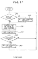
- Fig. 11 is a flow chart showing the method of changing the color of a selected item from the color of other, unselected items.
- the item relating to picture/sound quality m2 is selected by the roller 420f and entered by pushing roller 420f. According to the present invention it is provided that only this item m2 and its corresponding symbol m1 are displayed in white, for example, whereas all other items of m2 and m1 are displayed by a gray color, for example.
- the roller 420f of the remote controller 420 is pushed. If so, the method proceeds to step 220, otherwise it goes to step 230.
- step 220 zero is set into a line or row counter, and the method proceeds to step 230.
- step 230 the item of the menu that corresponds to the value in the line counter is displayed. That is, in the Fig. 8 menu m the selected item is displayed as a white color and the unselected items are displayed as a gray color. This sequence is performed by changing the RGB data of the video RAM of the system controller 41.
- step 240 the row counter is incremented and proceeds to step 250.
- step 250 the value of the row counter is checked and if selected item m2 of the menu m is the lowest row, then the method proceeds to step 260, otherwise it reverts to step 210.
- step 260 zero is loaded into or set in the row counter the same as in step 220, and the method proceeds to step 210 again.
- legend m2 and symbol m1 are checked row by row with 16.7 msec pulses and the RGB data is rewritten into the video RAM.
- the last row is reached, the first row of RGB data is rewritten into the video RAM by loading zero into the row counter.
- roller 420f is pushed, the row counter is forced to load zero and the first row of the video RAM is rewritten, in spite of not being the first row of row counter.
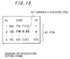
- a reservation screen is shown that is also able to be displayed by operation of the remote controller 420 and roller 420f.
- the item m2' that is currently being executed is displayed in white whereas all other items are displayed by different color from m2', for example, gray.
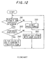
- the flow chart for accomplishing this is shown in Fig. 12, in which in step 310 it is determined if it is the reservation screen being displayed, if so, then the method proceeds to step 320, otherwise it to goes step 330. At step 320, it is determined whether there is an item currently being executed. If so, the method proceeds to step 340, otherwise it goes to step 350. At step 330 other operations are performed and the method reverts to step 310 again.
- step 340 the RGB data in the video RAM relating to the currently executed item m2' are changed, and the method starts over again.
- step 350 because there is no currently selected item the video RAM is rewritten so that all items are of same color, and the method returns to step 310.
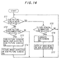
- step ST1 the system controller 41 decides whether there is a sub-screen menu or not on the sub-screen 36b. If there is, then the method proceeds to step ST5, otherwise step ST2 is next.
- step ST2 it is determined if the sub-screen item 36b1 was selected at the main menu, and if so, then go to step ST3, otherwise go to step ST1.
- step ST3 the system controller 41 controls the display microcomputer 45 to the display sub-screen menu on the sub-screen 36b and the method proceeds to ST4 at which time the picture image is displayed on the sub-screen 36c.
- step ST5 it is determined if item 36b1 is selected on the main menu, and if so then go to step ST6, otherwise go to step ST1.
- the system controller 41 controls the picture-in-picture circuit 34 to erase sub-screen 36c and the method proceeds to step ST7.
- the system controller 41 displays the main menu on the sub-screen 36b and returns to step ST1. That is the screen swap operation.
- BS setting item 36b 3 is selected from main menu of Fig. 5
- items 36b 31 , 36b 32 , 36b 33 , 36b 34 , 36b 35 , 36b 36 , and 36b 37 are displayed on the screen, along with the cursor 36b 30 .
- the input prohibited items are as follows, sound selection item 36b 32 in the B mode, the antenna level item 36b 36 except during BS receiving, and decoder input change over item 36b 37 .
- the display microcomputer 45 operates to dim sound change-over item 36b 32 , as shown by the dotted background in Fig. 15b.
- timer item 36b 4 When timer item 36b 4 is selected on the main menu of Fig. 5, there are many items displayed as shown in Fig. 16a comprising the timer menu, such items are shown at 36b 41 , 36b 42 , 36b 43 , 36b 44 , 36b 45 , 36b 46 , 36b 47 , and 36b 48 in Fig. 16a, along with cursor 36b 40 .
- the user selects the desired items using the cursor switches 62, 63 and the enter switch 64 of the remote controller 60, while watching the timer menu on the sub screen 36b. For example, when the user moves the cursor 36b 40 to the sleep item 36b 42 and pushes the enter key 64, the display microcomputer 45 operates to dim all items except the selected sleep item 36b 42 , and the system controller 41 starts a time count and shuts down the power after a predetermined time period has elapsed.
- a recording start time for BS recording reservation item 36b 44 a BS recording reservation item 36b 44 unless several required parameters have been set
- a program reservation item 36b 46 unless several required parameters corresponding to program reservation setting item 36b 45 have been set.
- the display microcomputer 45 controls to dim the program reservation item 36b 46 , as shown by the dotted background in Fig. 16b.
- miscellaneous setting menu 1 or the miscellaneous setting menu 2 are displayed alternately on the sub-screen 36b.
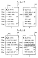
- this miscellaneous setting menu 1 as shown in Fig. 17a, there are displayed items 36b 51 , 36b 52 , 36b 53 , 36b 54 , 36b 55 , 36b 56 , and 36b 57 , along with cursor 36b 50 .
- the user selects the desired item by using the cursor switches 62, 63 and the enter switch 54 of the remote controller 60, while watching the miscellaneous setting menu 1 displayed on the sub-screen 36b.
- the display microcomputer 45 operates to dim all setting items except the selected bilingual item 36b 53 , and the system controller 41 controls the audio processing circuit 37 for transmitting the selected main or sub-sound to the speaker 38.
- miscellaneous setting menu 2 As shown in Fig. 18a, there are displayed items 36b 61 , 36b 62 , 36b 63 , 36b 64 , 36b 65 , 36b 66 , and 36b 67 , along with cursor 36b 60 .
- the user selects the desired item by using the cursor switches 62, 63 and the enter switch 64 of the remote controller 60, while watching the miscellaneous setting menu 2 displayed on the sub-screen 36b.
- the display micro computer 45 operates to dim all other setting items except the selected remote control signal receiving confirmation sound item 36b 67 , and the system controller 41 controls the audio processing circuit 37 so as not to generate the confirmation sound from the speaker 38.
- the miscellaneous setting menu 1 shown in Fig. 17a is displayed by selecting the miscellaneous setting item 36b 5 using the cursor switches 62, 63 and the enter key 64.
- the miscellaneous setting menu 1 after selecting the bilingual item 36b 53 , the main sound is set as an output sound, and all items except the bilingual sound item 36b53 are dimmed, and the main sound is reproduced through the speaker 38.
- the bilingual item 36b 53 becomes a prohibited item because there is no bilingual mode in the VTR input mode.
- This television receiver tells the user that the selection is prohibited by dimming the bilingual item 36b 53 and returning the sub-screen 36b 1 to the miscellaneous setting menu 1. After that, when the VTR 70 is connected and operated, based on the video signal from the VTR 70 the operation of setting the bilingual item 36b 53 is prohibited. Thus, it prevents a mistake relating to resetting the setting value of the bilingual mode in the memory 42 by misoperation of the change-over bilingual mode item.
- the television receiver of this invention can provide good conditions for visual confirmation and easy operation.
- the control according to selected item is completed, for example, in Fig. 6a after setting the signal source to the VTR 70, the user can know the condition not to attempt to set the channel by the dimmed display of the channel item 36b 13 , as shown in Fig. 6c. That is, when the source is set to the VTR 70 by dimming channel item 36b 13 on the sub-screen menu the user will know not to change the channel, so there is no need to store any such data in the memory 42. This means that data for only one screen can be used in common with plural states, and only a small capacity for the memory 42 is required.
- the apparatus of this invention affords many advantages, such as the following, and there are many functions for achieving high performance, and many items corresponding to these functions are displayed on the display area. When one of these displayed items is selected, the other items are displayed in a dimmer style. These features make it easier to confirm the set item by the user, and make operation easier for the user. Furthermore, by dimming items on the menu that are not able to be selected, there is no need to memorize a menu screen that contains selection prohibited items, so that only one menu screen is used in common with plural states and so memory capacity can be reduced. Furthermore according to this invention by moving the cursor smoothly in a sequential fashion, there is an advantage that the user can operate easily and correctly to select items. In the menu that contains an item being performed, this item can be displayed in a different color than the other items, and this function makes the user recognize what item is being performed and prevents mistakes in changing parameters.
Description
- This invention relates generally to controlling a television receiver with a remote commander and, specifically, to controlling a television having the picture-in-picture feature.
- Recently television receivers have been equipped with various functions, such as the so-called picture-in-picture function and the ability to preset a TV channel program for viewing or recording. In the picture-in-picture function, the overall area of the screen is selected as a main screen, and a portion of this main screen is selected as a sub-screen on which pictures or images of another TV channel are displayed. Recent television receivers also include a built-in satellite broadcasting tuner to receive satellite broadcasting programs.
- In addition, a recent television receiver has been proposed in which, after a mechanical switch is switched on to place it into a standby state, the main power to the receiver can be switched on or off by a remote controller. When the main power is switched on, each of the tuners for the VHF/UHF and the satellite broadcast is supplied with power and carries out its receiving and transmitting operations. On the other hand, when the main power is switched off, the supply of the power to each of the tuners for VHF/UHF and for the satellite broadcast is deenergized, and the receiving and transmitting operations thereof are stopped.
- The television receiver described above also enables a desired reserved program to be received at a desired reserved time, and also can perform various settings such as a color adjustment setting, a volume adjustment setting, and the like by manipulation of a remote controller. Desired ones of the above items are displayed on the screen of the cathode-ray tube of the television receiver, and then parameters for the displayed items are set.
- Also in a recent television receiver, various functions are improved by displaying the contents of operations, the operation sequences, and the receiving conditions for various functions in displays called a menus. These menus are displayed on the sub-screen, for example, in order to simplify utilization of these functions by a user. That is to say, the attempt is made to improve the man-to-machine interface function.
- When the operation of the menu display is performed by a user, the setting items with regard to the plural functions provided by the television receiver are first displayed on the sub-screen. A selection is then made of one of these plural setting items by employing a cursor moved by operation of the remote controller, and new setting items, for example, the contents of operation and sequence of operation, are displayed. Next, when the user wants to register a recording reservation of a desired TV program for example, the recording start and stop times and the channel number are set by the user.
- To confirm the contents of the selected setting items by the user, when one of the plural setting items is selected, the color of this selected item is changed, blinked, and nigh-lighted. Nevertheless, the color changing, blinking, and high-lighting of these known television receivers does not make it easy for the user to confirm the selected operations.
- Another proposed television apparatus displays only selected items without other setting items, but it is nevertheless necessary for the receiver to prepare an image for displaying all items in order to display only selected items. This results in the drawback that a large amount of memory capacity is needed for displaying a menu.
- Simplification of operation of recent television receivers is also desired. One proposal for such simplification, is to display a sequence of a menu on the screen, select the desired item by a moving cursor, and display the selected item for parameter setting. But in this menu setting method, particularly when moving the cursor on the screen by a remote controller, the cursor is frequently moved incorrectly, because of differences in the timing of transmission of operation data from the remote controller to the television and the timing of the scanning screen of the menu. Moreover, when the reserving operation is performed, if the user performs another operation, there is the possibility of mistake, for example, the undesired deletion of a parameter.
- JP-A-03/91385 discloses a television including means for displaying an operation menu, comprising display means for receiving a video signal displaying a picture and an operation menu, a video processing circuit for processing signals of the picture and the menu, user-operable operation means for controlling an operation indicated in the operation menu, display control means for controlling the appearance of marks and/or characters in the menu, and system control means for controlling the display control means and operation of the apparatus.
- GB-A-2155714 discloses a television system having a main menu, exemplified at 006 on Figure 4b, and a series of sub-menus, such as (i) the picture menu 013 in Figure 4d, (ii) the audio menu 026 in Figure 4g, (iii) the pre-sets menu at 033 in Figure 4j, (iv) the switch settings menu 041 on Figure 4k and (v) the features menu 051 on Figure 41. It is possible to visit the individual sub-menus from the main menu and to return to the main menu either on completion of adjustments or for operation on a different menu item of the main menu.
- Funkschau, 18, 1989, pages 128 to 132 discloses a TV control system in which a horizontal strip menu is displayed on screen and sub-menus depend down from the items in the strip menu. Only currently possible menu items are displayed and the controller operates to ensure that nonsensical commands are not displayed at all.
- Accordingly, it is an object of the present invention to provide a television receiver that overcomes the above drawbacks inherent in previously proposed receivers.
- According to one aspect of the present invention, a television receiver can support many features without losing ease of operation, and provides a very easy-to-see-display. For example, the menu is in common with many items of operations and only a small amount of memory capacity is needed. It then becomes easy to select an item by moving the cursor, and it is easy for the user to recognize which item is selected and operated correctly, and to prevent mistakes in erroneously changing parameters.
- The present invention is characterised by the features of
claim 1. - The present invention will be further described in the following detailed description of illustrative embodiments thereof, to be read in connection with the accompanying drawings, in which like reference numerals represent the same or similar elements, and in which:-
- Fig. 1 is a block diagram of a television receiver comprising a VHF/UHF tuner, a BS tuner, a signal selector, and a controller formed by a microcomputer according to an embodiment of the present invention:
- Fig. 2 is block diagram of a television receiver according to another embodiment of this invention that receives a control signal from a remote controller for moving a cursor relative to a menu on the screen of the receiver;
- Fig. 3 is a plan view of a remote controller for use with the television receivers of Figs. 1 and 2;
- Fig. 4 consists of images showing a main screen and a sub-screen on the cathode-ray tube of the receivers of Figs. 1 and 2;
- Fig. 5 is a view of a menu display on a screen of the television receivers of Figs. 1 and 2;
- Fig. 6 consists of views of other menu displays on a screen of the television and showing half-tones and a cursor;
- Fig. 7 is a schematic of a circuit of the television receiver of Figs. 1 and 2 for controlling the display on the sub-screen;
- Fig. 8 is a view of another menu showing a main menu and a hierarchy thereof;
- Fig. 9 is a view of another menu showing an nth hierarchy thereof;
- Fig. 10 is a flow chart of a method of moving a cursor of the television screen according to this invention;
- Fig. 11 is flow chart of method of a moving a cursor for selecting an item on the screen;
- Fig. 12 is a flow chart of a method for changing the color of a displayed menu;
- Fig. 13 is view of a display operation for reserving or confirming timer operation and recording;
- Fig. 14 is a flow chart of a method for selecting the menu on the sub-screen of the television receiver of Figs. 1 and 2;
- Figs. 15 and 16 are views showing displaying the menu when color changing of a selected, displayed item; and
- Figs. 17 and 18 are views showing displaying the menu when a half-tone color display at the item of not being selected is not available.
-
- Fig. 1 is a block diagram of a television receiver according to an embodiment of this invention including a VHF/UHF receiving section for receiving NTSC colortelevision signals and sound signals, and a receiving section for receiving signals from a broadcast satellite (BS) or from a communication satellite (CS). A control section controls and selects signals and a sound section reproduces the sound at a loudspeaker.
- In the VHF/
UHF receiver 12, to which a Yagiantenna 11 is connected, the desired channel from the VHF/ UHF band is selected and the color video signal and audio sound signal are produced. - The satellite broadcast receiver is connected to a
parabola antenna 21 that receives the 12 GHz signal broadcast by the satellite, and the received signal is converted in frequency to a 1 GHZ signal using aBS converter 22. The converted signal is fed to abroadcast satellite tuner 23 that selects the desired channel, performs automatic gain control (AGC), IF amplitude, FM demodulation, de-emphasis, and reduction of an energy dispersal signal. TheBS tuner 23 reproduces the video signal and audio signal modulated by pulse shift keying (PSK) and pulse code modulation (PCM). When the A mode of BS broadcast is received, theBS tuner 23 reproduces four channels of PCM sound signals, and when the B mode is received, theBS tuner 23 reproduces two channels of PCM signals. APSK demodulator 25 demodulates the signal and also detects the scrambling state of the signal, and a digital to analog (D/A)converter 26 converts the PCM digital audio signal from thePSK demodulator 25 to an analog sound signal. Alevel detector 27 detects the level of the received signal at theBS antenna 21 by detecting the output signal of theBS tuner 23 in the 8 MHz band. The tuned signal output from theBS tuner 23 is also fed tooutput terminals 28a, 28b, and 28c to external decoders. TheBS tuner 23 is also connected to aninput terminal 28d for receiving keyed AFC pulse from the MUSE signal. - The BS receiving section including the
BS tuner 23 selects the desired channel and supplies the signal to the output terminals when the received signal is scrambled or when it is a MUSE format signal. If the received signal is some other sort of signal, it does signal processing as if it was an NTSC signal and changes over the sound signal to two channels corresponding to the video signal or the sound signal to two channels not corresponding to the video signal, respectively. - A MUSE down
converter 51 can be connected for use in receiving a MUSE format signal (multiple sub-Nyquist encoding) to reproduce an HDTV signal. This HDTV signal is a TCI luminance and chrominance signal and a PCM sound signal. A Japanese Satellite Broadcast (JSB)decoder 52 can be connected for decoding a JSB scrambled broadcasting signal, and a communications satellite (CS) decoder can be connected for decoding a scrambled signal broadcast by a communications satellite. - The respective signals at
output terminals converter 51,JSB decoder 52, andCS decoder 53, as well as outputs from the VHF/UHF tuner 12 and thevideo processing circuit 24 are selected for display by an audio-video (AV)switch 32. TheAV switch 32 also selects audio signals from the VHF/UHF tuner 12, the D/A converter 26, the MUSE downconverter 51, theJSB decoder 52, and theCS decoder 53. Avideo processing circuit 33 processes the color television signal selected by theAV switch 32 to an RGB signal for display. A picture-in-picture circuit 34 performs the necessary picture-in-picture processing in the well-known manner. An RGB switch switches the RGB signals from the picture-in-picture circuit 34 in response to a signal from the control section. A cathode-ray tube 36 displays the images of the selected signal, and anaudio processing circuit 37 processes the audio to provide tone control and the like for reproduction over aloudspeaker 38.Output terminals optional VTR 70 for recording. Similarly,input terminals 31i, 31j receive video and audio signals from theoptional VTR 70 for playback. - The
video processing circuit 33 supplies the video signal to the cathode-ray tube 36 for displaying and theaudio processing circuit 37 supplies the audio signal to theloudspeaker 38. When the signal of the selected channel is scrambled, these circuits operate for displaying and reproducing the unscrambled video and audio signals from theJSB decoder 52, for example. These terminals supply the color television signal and the audio signal selected by theAV switch 32 to theVTR 70 and, if necessary, for displaying picture-in-picture, the menu of operation, and the contents of the many functions and settings. - The
system controller 41 controls the outputs based on the detected scrambled state of the PCM sound signal from thePSK demodulator 25 and on the state of the color television signal fromvideo processing circuit 33. Amemory 42 stores the control program and other operating settings set by the user. ABS microcomputer 43 controls the channel selection of theBS tuner 23. A digital-to-analog (D/A)converter 44 converts data from thesystem controller 41 to analog signals for controlling the volume of the reproduced sound. Thedisplay microcomputer 45 controls a menu display based on data from thesystem controller 41. Areceiver 47 receives infrared radiation control signals from theremote controller 60. Thesystem controller 41, thevideo processing circuit 33, the picture-in-picture circuit 34, theaudio processing circuit 37, and thememory 42 are connected to each other by an I2C bus. - In the similar television receiver of Fig. 2, an
antenna 11 receives a VHF/UHF television signal and supplies it to thetuner 12.Tuner 12 is used to select the desired channel in response to a control signal from acontroller 41 formed of a microcomputer that includes a video RAM, a ROM, and an additional RAM, all of which are internal. Thecontroller 41 supplies control signals based on channel information signals supplied from a control panel 18 and from aremote controller 420 through areceiver 419. Thecontroller 41 also memorizes parameters set by the user in aROM 417 and performs many other operations synchronized by an oscillation signal from an oscillator 416a. - The
tuner 12 changes the frequency of the television signal to the IF signal frequencies, 58.75 MHz in the video and 54.25 MHz in the audio, respectively. These IF signals are amplified, detected, auto-gain controlled, and then supplied to theAV switch 32. TheAV switch 32 supplies video and audio signals from aninput terminal group 31, thetuner 12, and aBS receiver 422 to thevideo processing circuit 33 and to theaudio processing circuit 37 under control of a signal from thecontroller 41. - The
VTR 70 is connected to theinput terminal group 31 and to the output terminal group 31' for both video and audio signals. - The
video processing circuit 33 separates the chrominance signal from the composite video signal and generates a color difference signal. Thevideo processing circuit 33 then generates RGB signals and supplies these signals to the cathode-ray tube 36. Thevideo processing circuit 33 also generates deflection signals for vertical and horizontal deflection fed to vertical and horizontal deflection coils not forming a part of the present invention. Thevideo processing circuit 33 also supplies the RGB signals for displaying control characters on the cathode-ray tube 36 under the control of thecontroller 41. Anaudio processing circuit 37 processes the audio signals and supplies them to theloudspeaker 38. -
BS receiver 422 receives the satellite broadcast signal, for example, a 12 GHz signal, through aparabola antenna 21. TheBS receiver 422 receives the FM TV signal and changes the frequency to the 1 GHz intermediate frequency (IF). TheBS tuner 23 selects the band of the IF signal in response to control signals from thecontroller 41 as determined by thecontrol panel 418 or theremote controller 420 and FM demodulates and supplies the demodulated signal to avideo processing circuit 24 and to anaudio processing circuit 25, respectively. -
Video processing circuit 24 processes the FM video signal and supplies a demodulated signal to theAV switch 32. Theaudio processing circuit 25 demodulates and converts to analog the 4-phase DPSK audio signal and feeds the processed audio signal to theAV selector switch 32. Apower supply 421 energizes themain portion 410 of the television receiver and theBS receiver section 422. Thepower supply 421 is connected by aplug 424 to a source of AC power. Thispower supply 421 supplies power to the system. When aswitch 415 connected to themicrocomputer 41 is operated themicrocomputer 41 is energized by power converted by atransformer 425 and placed in stand-by. In the case of watching TV or recording signals by a VTR, the user operates switches on thecontrol panel 418 or on aremote controller 420. By pushing power key 420a onremote controller 420 an infra-red signal is received through receivingunit 419 and fed to themicrocomputer 41 to control thepower supply 421. By pushing change input key 420b. theAV selector switch 32 selects an input signal from thetuner 12, theBS tuner 23, or from theinput terminal group 31 under control of themicrocomputer 41. Each stroke of the change input key 420b sequentially changes the outputs of the video and audio on the cathode-ray tube 36 and thespeaker 38. By pushing channel changing key 420c, if the + key is pushed then the channel number increases and if the - key is pushed then the channel number is decreased. The channel number signal is also supplied to themicrocomputer 41.Tuner 12 andBS tuner 23 select the channel and the desired image signal is displayed on the screen of the cathode-ray tube 36 by using the channel changing key 420c. When operating the volume key 420d, if the + key is pushed then the sound volume increases and if the - key is pushed then the sound volume decreases. By pushing the menu key 420e, menu data is written into the video RAM in themicrocomputer 41 and this data is read out and supplied to the cathode-ray tube 36 throughvideo processing circuit 33 as RGB signals, and the menu is displayed. This data in the video RAM is read from a ROM that is also a part of themicrocomputer 41. - Fig. 3 shows the configuration of the keys of the
remote commander 60 shown in Fig. 1.Menu switch 61 displays the menu on the sub-screen of the cathode-ray tube 36. Cursor switches 62, 63 move the cursor left to right or top to bottom on the screen for selecting one of the items of the menu.Decision switch 64 selects the item indicated by thecursor. Power switch 65 operates the power supply of the television set.Input changing switches Numerical keys 69 change the channel numbers. Thus, theremote controller 60 selects a channel desired by the user and selects a color television signal from thevideo processing circuit 24 by operating theAV switch 32, and displays the image on the cathode-ray tube 36. The remote controller selects a sound signal from the D/A converter 26 by operating theAV switch 32 and outputs the sound throughspeaker 38. For example, in mode A, the television sound or an independent sound is selected and in mode B it selects the television sound. The received video signal is supplied to theJSB decoder 52 if the PCM sound channel is determined to be scrambled. The signal decoded by theJSB decoder 52 is then fed through theAV selection switch 32 and displayed on the cathode-ray tube 36 and the sound is reproduced by thespeaker 38. When the received signal is not scrambled it is supplied directly to the CRT and the speaker and not through theJSB decoder 52. If the independent sound mode is selected and the user selects a blank picture mode, the control section controls the power supply to interrupt power to thevideo processing circuit 33 and the cathode-ray tube 36, and to provide power to theBS converter 22, theBS tuner 23, thePSK demodulator 25, the D/A converter 26, theaudio processing circuit 37, and thesystem controller 41. - If the user sets the channel reservation mode to avoid failing to view or record a program by later selecting an undesired channel, the control section selects the predetermined BS channel, and outputs color video signal and sound signal to the
VCR 70 through theoutput terminals remote controller 60. - If the user operates the
remote controller 60 to display the menu on the screen, the control section controls thedisplay microcomputer 45 for displaying a sequence for recording a BS signal, for example, in the sub-screen. If the user operates theremote controller 60 to perform the picture-in-picture mode, the control section controls theAV switch 32, and the picture-in-picture circuit 34 for displaying the BS program on the main screen and a VHF/UHF TV program in the sub-screen, for example. More specifically, when the user sets the channel number for viewing a VHF/UHF television broadcast by using thenumerical keys 69 of theremote controller 60, thesystem controller 41 receives the channel number signal from theremote controller 60, controls the VHF/UHF tuner 12 to select the set channel, and controlsswitches 32a, 32c for selecting the video and audio signals from thetuner 12, respectively. Thevideo processing circuit 33 supplies the RGB signal converted from the color video signal fed by switch 32a to the cathode-ray tube 36. Theaudio processing circuit 37 supplies the audio signal to thespeaker 38 with suitable processing, such as tone control. Thus, the user can watch the desired program on the VHF/UHF band. - For confirming the contents of the operations set by the user, the
system controller 41 supplies channel number data to thedisplay microcomputer 45 through the I2C bus. Thedisplay microcomputer 45 supplies an RGB signal, for displaying the channel number at the upper-right edge on the screen, for example, to thevideo processing circuit 33 through theRGB switch 35. Thevideo processing circuit 33 superimposes the RGB channel number onto the image of the broadcast program of the VHF/UHF band. - When the user sets the BS channel by using the
remote controller 60, thesystem controller 41 receives a control signal from theremote controller 60. controls theBS tuner 23 to select the BS channel, and detects whether the received program is an NTSC or hi-vision (HDTV) signal based on the state of synchronization of the PCM sound signal from thePSK demodulator 25 or based on the signal level at thelevel detection circuit 27. If an NTSC signal is detected, thesystem controller 41 controls theAV switch 32 to select the signal from thevideo processing circuit 24 and the signal from the D/A converter 26. If a hi-vision signal is detected, thesystem controller 41 controls theAV switch 32 to select the signal from the MUSE downconverter 51. - In the normal mode; the analog sound signal is converted to a PCM signal and modulated by PSK, and then frequency division multiplexed. In the hi-vision mode, the sound signal is converted to special differential PCM signal and TCI modulated in the period of the vertical synchronization signal. The
system controller 41 detects that the signal is an NTSC signal if the received level at thelevel detection circuit 27 is high and it detects the synchronization signal of the PCM sound signal. It is decided that the received signal is a hi-vision signal if the received level is high and the synchronization is unlocked. Detection of a normal signal or hi-vision signal is also made based on the presence of a keyed AFC pulse supplied by MUSE downconverter 51 to theBS tuner 23 through theinput terminal 28d. - The selected color video signal is supplied to the
video processing circuit 33, and the selected audio signal is supplied to theaudio processing circuit 37, so that the user can watch each channel by only the desired setting channel in spite of the kind of BS program mode. - When the user operates the
remote controller 60 for displaying VHF/UHF program on the sub-screen at the time of watching a BS program, thesystem controller 41 receives a control signal corresponding to the picture-in-picture operation from theremote controller 60, controls the VHF/UHF tuner 12 for selecting the set channel, and controls the switch 32b for selecting the color video signal from the VHF/UHF tuner 12. The selected color video signal is supplied to the picture-in-picture circuit and converted to the RGB signal and supplied as a signal for the sub-screen to thevideo processing circuit 33 through theRGB switch 35. In this way, the user can watch a BS program on the main screen and a VHF/UHF program on the sub screen. - If the user sets the channel to a scrambled channel of the BS, the
system controller 41 detects the scrambled state of the program based on a state of the PCM sound signal fromPSK demodulator 25 and selects color video signal from thevideo processing circuit 24 and sound signal from the D/A converter 26, if the program is not scrambled. When the program is scrambled, it selects the color video and audio signal from theJSB decoder 52. When the user wants to listen to the sound of the independent sound program, if the sound signal of the television is scrambled, it selects the independent sound signal from theJSB decoder 52, and if the sound signal of the television is not scrambled, it selects the independent sound signal from the D/A converter 26. The number of combinations of scrambled and not scrambled programs is four, because there are scrambled and not scrambled states in the television sound signal (the same as video signal), and there are scrambled and not scrambled states in the independent sound signal. When the television sound signal is selected, thesystem controller 41 performs control based on the scrambled state of the television sound signal, and the user can watch both scrambled and non-scrambled programs without manually changing the mode. When the independent sound signal is selected, thesystem controller 41 performs control based on the scrambled state of the television sound signal and the independent should signal, and the user can listen in each case without manually changing the mode. - If the video signal is not scrambled, or if the video signal is scrambled and the non-display picture mode is selected, the signal path is not through the
JSB decoder 52, so the sound quality is not damaged by passing through many circuits. The decision as to whether the program is scrambled or not is based on the 12th bit of a group of control bits of the PCM sound signal that shows the state of scramble of the video signal. - When the user sets a channel in the CS broadcasting system by using the
remote controller 60 for listening to a music program, for example, thesystem controller 41 receives the control signal from theremote controller 60, controls theBS tuner 23 to select the set channel, and detects whether it is scrambled or not based on the state of the PCM sound signal from thePSK demodulator 25. If the not scrambled state is detected, theAV switch 32 is controlled to select a sound signal from the D/A converter 26. On the contrary, if a scrambled signal is detected, theAV switch 32 is controlled to select the sound signal output from theCS decoder 53. The sound signal of a nonscrambled program is converted to PCM signal and PSK duplex frequency modulated, and the sound signal of a scrambled program is first scrambled, PCM converted, and then PSK duplex modulated. Thesystem controller 41 detects the scrambled or non-scrambled states based on the 8th bit of a range of bits from thePSK demodulator 25. The selected sound signal is supplied to theaudio processing circuit 37, and the user can listen to the desired program without noticing whether the program is scrambled or not. According to this invention, the mode conversion of a scrambled or nonscrambled signal is not only enabled automatically as described but also permits manual selection using theremote controller 60. - When the user presses the
menu switch 61 of theremote controller 60, thesystem controller 41 receives a control signal for displaying the main menu relating to each functional setting, and supplies corresponding data to thedisplay microcomputer 45 for displaying the main menu. The characters used for displaying the main menu can be stored in thememory 42 and output onto the I2C bus. Thedisplay microcomputer 45 displays the main menu on the sub-screen 36b, which is a part of themain screen 36a of the face of the cathode-ray tube 36 shown in Fig. 4b, based on this data frommemory 42. - Fig. 5 shows the main menu display including a
display setting parameter 36b1 of the sub screen in the picture-in-picture operation, aparameter 36b2 for setting picture and sound qualities, aparameter 36b3 for changing over the sound in the BS receiving mode, aparameter 36b4 for setting the recording reservation, aparameter 36b5 for setting the change-over of a bilingual sound mode, and acursor 36b0. Thedisplay microcomputer 45 supplies an RGB signal for displaying the setting parameters and cursor to thevideo processing circuit 33 through theRGB switch 35. - The
video processing circuit 33 converts the color video signal at theAV switch 32 to the RGB signal, switches this RGB signal and the RGB signal from theRGB switch 35, displays the picture based on the signal from the AV switch 32a on themain screen 36a and displays the picture based on the RGB signal from theRGB switch 35 on thesub screen 36b, as shown in Fig. 4b. - The user can move the
cursor 36b0 by pushing cursor switches 62, 63 of theremote controller 60 while watching the displayed menu. If the user pushes theenter switch 64, the setting parameter pointed to by thecursor 36b0 is selected, and a new menu is displayed corresponding to the selected parameter. - When the user selects from the main menu of Fig. 5 the
sub-screen parameter 36b1, twosub screens main screen 36a, as shown in Fig. 4C. A color video signal from one of thevideo processing circuit 24 or theVTR 70 is selected by the switch 32b of theAV switch 32, and the selected picture is displayed on the sub-screen 36c. - The sub-screen menu is displayed on sub-screen 36c and as shown in Fig. 6a includes
menu item 36b11 for returning sub-screen display to the main menu,item 36b12 for setting the source of the display on sub-screen 36c,item 36b13 for setting the source channel,item 36b14 for setting the sound volume corresponding to the picture in sub-screen 36c at the earphone output terminal,item 36b15 for swapping the pictures in themain screen 36a and the sub-screen 36c,item 36b16 for setting the position of the sub-screen 36c on themain screen 36a,item 36b17 for setting the size of the sub-screen 36c, and acursor 36b10. As a result, the user can set new parameters of thesub screen 36c, while confirming the displayed picture on the sub-screen 36c. For example, when the user elects to swap the main and sub screen displays by selectingitem 36b15 using the cursor switches 62, 63 and theenter switch 64, thesystem controller 41 swaps the images of themain screen 36a and the sub-screen 36c, controls theAV switch 32, and stores setting parameter in thememory 42. - The
system controller 41 dims all other items being displayed except the selected setting parameter. This is the so-called half-tone and in the example of Fig. 6b all items exceptitem 36b15 are shown dimmed by the dotted background. The data for dimming is sent bycontroller 41 to thedisplay microcomputer 45 by the I2C bus. Thedisplay microcomputer 45 controls the reduced RGB signal levels of all items except theswap item 36b15 to thevideo processing circuit 33 through theRGB switch 35. - An embodiment for accomplishing this display dimming is shown in Fig. 7. The circuit for varying the output level of the
display microcomputer 45 comprises resistors for DC bias 81R, 82R, resistors for matchingoutput impedance output level 85R.Resistors Resistors display microcomputer 45 and anoutput terminal 86R.Resistor 85R is connected to a point between a signal output I of thedisplay microcomputer 45 andoutput terminal 86R. When the dimmer mode is generated, thedisplay microcomputer 45 shifts the level of signal I to low. Normally, the level of that signal I is high or open circuited. As a result, the level of the R signal supplied to theRGB switch 35 through theoutput terminal 86R is reduced. The blue (B) and green (G) signals are controlled the same as the R signal, and level controlled RGB signals are supplied to thevideo processing circuit 33. After that all items except theswap item 36b15, for example, are dimmed, and the user can confirm the selected setting item easily. - In this sub-screen menu, if the user tries to set the source of the sub-screen 36c display to the
VTR 70, it is impossible to change the channel of the sub-screen 36c to theVTR 70, because there is no definition of the channel when theVTR 70 is reproduced. As shown in Fig. 6c, after selecting the source to beVTR 70, the display for thechannel setting item 36b13 is dimmed, so the user can easily recognize that this item is not suitable to select. Thus, thememory 42 need not memorize new menu data after selectingVTR 70 as the source and, because only one menu data is used in common with plural states of the system, the required capacity of thememory 42 is minimized. - Another menu is shown in Fig. 8 and will be described in connection with the television receiver of Fig. 2. When the user pushes the menu key 420e of the
remote controller 420, the menu picture shown in Fig. 8 is displayed on the screen of the cathode-ray tube 36. The selection anddecision roller 420f is used to move a cursor m3 when the menu is displayed on the screen of the cathode-ray tube 36. By rotating thisroller 420f in one direction or the other, the cursor m3 is moved at the left of symbols ml having legends m2, and the selected item m2 is entered by depressingroller 420f and closing internal switch contacts. - When item m2 is selected from the menu and entered a so-called nth layer of hierarchy is displayed on the screen, as shown in Fig. 9. This means that the selected item is placed at the head of the menu, so that when that main menu is revisited it makes it easy for the user to remember the item most recently selected. By moving
roller 420f, the desired item m2 is selected by pushing 420f the desired item m2 is entered based on the menu of Fig. 8. A sub-menu is then displayed and utilized and following that the menu in Fig. 9 is displayed. Parameter data of each item set by this process are memorized atROM 417, which may be embodied as an EEPROM. If the user wants to stop the display the menu key 420e is pushed, and thesystem controller 41 stops sending menu data to the display. By providing control of the menu display in this way the selected item of the menu may also be displayed as a different color. - Fig. 10 shows an operational flow chart of the method for moving cursor m3 in the menu by the
remote controller 420. In Fig. 10, atstep 100 it is determined whether the cursor counter internal to themicrocomputer 45 has been altered. If so the method proceeds to step 110, if not, it reverts to step 100 again. In that regard, by rollingroller 420f of theremote controller system controller 41 through thereceiver 419. Atstep 110, if the moving direction is downward then the method proceeds to step 120, otherwise the method proceeds to step 130. At thestep 120, if the difference in the value of cursor counter and a register used to determine if the cursor counter was altered is greater than two, then the method proceeds to step 140, otherwise the method proceeds to step 100. Atstep 130, if the difference in the value of the cursor counter and the register is greater than two, then the method proceeds to step 150, otherwise go to step 100. Atstep 140, the cursor counter is incremented by one and this value is stored in the register, and the method reverts back to step 100. Atstep 150, cursor counter is decreased by one and this value is stored in the register, and the method reverts back to step 100. Thus, by each rolling of theroller 420f of theremote controller 420, the cursor m3 is moved step by step correctly. - Fig. 11 is a flow chart showing the method of changing the color of a selected item from the color of other, unselected items. As shown in relation to Fig. 8,, the item relating to picture/sound quality m2 is selected by the
roller 420f and entered by pushingroller 420f. According to the present invention it is provided that only this item m2 and its corresponding symbol m1 are displayed in white, for example, whereas all other items of m2 and m1 are displayed by a gray color, for example. At thefirst step 210 it is determined if theroller 420f of theremote controller 420 is pushed. If so, the method proceeds to step 220, otherwise it goes to step 230. Atstep 220 zero is set into a line or row counter, and the method proceeds to step 230. Atstep 230 the item of the menu that corresponds to the value in the line counter is displayed. That is, in the Fig. 8 menu m the selected item is displayed as a white color and the unselected items are displayed as a gray color. This sequence is performed by changing the RGB data of the video RAM of thesystem controller 41. Atstep 240, the row counter is incremented and proceeds to step 250. Atstep 250, the value of the row counter is checked and if selected item m2 of the menu m is the lowest row, then the method proceeds to step 260, otherwise it reverts to step 210. Atstep 260, zero is loaded into or set in the row counter the same as instep 220, and the method proceeds to step 210 again. Whenroller 420f is not pushed, legend m2 and symbol m1 are checked row by row with 16.7 msec pulses and the RGB data is rewritten into the video RAM. When the last row is reached, the first row of RGB data is rewritten into the video RAM by loading zero into the row counter. Whenroller 420f is pushed, the row counter is forced to load zero and the first row of the video RAM is rewritten, in spite of not being the first row of row counter. - In Fig. 13 a reservation screen is shown that is also able to be displayed by operation of the
remote controller 420 androller 420f. When the reservation screen is displayed, the item m2' that is currently being executed is displayed in white whereas all other items are displayed by different color from m2', for example, gray. The flow chart for accomplishing this is shown in Fig. 12, in which instep 310 it is determined if it is the reservation screen being displayed, if so, then the method proceeds to step 320, otherwise it to goesstep 330. Atstep 320, it is determined whether there is an item currently being executed. If so, the method proceeds to step 340, otherwise it goes to step 350. Atstep 330 other operations are performed and the method reverts to step 310 again. Atstep 340 the RGB data in the video RAM relating to the currently executed item m2' are changed, and the method starts over again. Atstep 350, because there is no currently selected item the video RAM is rewritten so that all items are of same color, and the method returns to step 310. - The method for changing the main and sub-menu picture is represented in Fig. 14, in which in step ST1 the
system controller 41 decides whether there is a sub-screen menu or not on the sub-screen 36b. If there is, then the method proceeds to step ST5, otherwise step ST2 is next. At step ST2, it is determined if the sub-screen item 36b1 was selected at the main menu, and if so, then go to step ST3, otherwise go to step ST1. At step ST3 thesystem controller 41 controls thedisplay microcomputer 45 to the display sub-screen menu on the sub-screen 36b and the method proceeds to ST4 at which time the picture image is displayed on the sub-screen 36c. At step ST5, it is determined if item 36b1 is selected on the main menu, and if so then go to step ST6, otherwise go to step ST1. At step ST6, thesystem controller 41 controls the picture-in-picture circuit 34 to erase sub-screen 36c and the method proceeds to step ST7. At step ST7, thesystem controller 41 displays the main menu on the sub-screen 36b and returns to step ST1. That is the screen swap operation. - In Fig. 15a, if
BS setting item 36b3 is selected from main menu of Fig. 5,items cursor 36b30. In this BS setting mode, the input prohibited items are as follows,sound selection item 36b32 in the B mode, theantenna level item 36b36 except during BS receiving, and decoder input change overitem 36b37. When the B mode is received, thedisplay microcomputer 45 operates to dim sound change-overitem 36b32, as shown by the dotted background in Fig. 15b. - When
timer item 36b4 is selected on the main menu of Fig. 5, there are many items displayed as shown in Fig. 16a comprising the timer menu, such items are shown at 36b41, 36b42, 36b43, 36b44, 36b45, 36b46, 36b47, and 36b48 in Fig. 16a, along withcursor 36b40. - The user selects the desired items using the cursor switches 62, 63 and the
enter switch 64 of theremote controller 60, while watching the timer menu on thesub screen 36b. For example, when the user moves thecursor 36b40 to thesleep item 36b42 and pushes theenter key 64, thedisplay microcomputer 45 operates to dim all items except the selectedsleep item 36b42, and thesystem controller 41 starts a time count and shuts down the power after a predetermined time period has elapsed. - There are many prohibited items in this time menu shown in Fig. 16a, for example, a recording start time for BS
recording reservation item 36b44, a BSrecording reservation item 36b44 unless several required parameters have been set, aprogram reservation item 36b46 unless several required parameters corresponding to programreservation setting item 36b45 have been set. When the prerequisite parameters corresponding to programreservation setting item 36b45 are not entered, thedisplay microcomputer 45 controls to dim theprogram reservation item 36b46, as shown by the dotted background in Fig. 16b. - When the user selects the
miscellaneous setting item 36b5 in the main menu of Fig. 5, themiscellaneous setting menu 1 or themiscellaneous setting menu 2 are displayed alternately on the sub-screen 36b. In thismiscellaneous setting menu 1, as shown in Fig. 17a, there are displayeditems cursor 36b50. The user selects the desired item by using the cursor switches 62, 63 and the enter switch 54 of theremote controller 60, while watching themiscellaneous setting menu 1 displayed on the sub-screen 36b. For example, when the user moves thecursor 36b50 tobilingual sound item 36b53 and pushes theenter switch 64, thedisplay microcomputer 45 operates to dim all setting items except the selectedbilingual item 36b53, and thesystem controller 41 controls theaudio processing circuit 37 for transmitting the selected main or sub-sound to thespeaker 38. - In the
miscellaneous setting menu 2, as shown in Fig. 18a, there are displayeditems cursor 36b60. The user selects the desired item by using the cursor switches 62, 63 and theenter switch 64 of theremote controller 60, while watching themiscellaneous setting menu 2 displayed on the sub-screen 36b. For example, when the user movescursor 36b60 to a remote control signal receivingconfirmation sound item 36b67 and pushes theenter switch 64, the displaymicro computer 45 operates to dim all other setting items except the selected remote control signal receivingconfirmation sound item 36b67, and thesystem controller 41 controls theaudio processing circuit 37 so as not to generate the confirmation sound from thespeaker 38. - When the
menu key 61 of theremote controller 60 is pushed and the main menu shown in Fig. 5 is displayed themiscellaneous setting menu 1 shown in Fig. 17a is displayed by selecting themiscellaneous setting item 36b5 using the cursor switches 62, 63 and theenter key 64. In themiscellaneous setting menu 1, after selecting thebilingual item 36b53, the main sound is set as an output sound, and all items except the bilingual sound item 36b53 are dimmed, and the main sound is reproduced through thespeaker 38. In this selected state, if the input source of this television is set to theVTR 70, thebilingual item 36b53 becomes a prohibited item because there is no bilingual mode in the VTR input mode. This television receiver tells the user that the selection is prohibited by dimming thebilingual item 36b53 and returning the sub-screen 36b1 to themiscellaneous setting menu 1. After that, when theVTR 70 is connected and operated, based on the video signal from theVTR 70 the operation of setting thebilingual item 36b53 is prohibited. Thus, it prevents a mistake relating to resetting the setting value of the bilingual mode in thememory 42 by misoperation of the change-over bilingual mode item. - By means of above-described function, the television receiver of this invention can provide good conditions for visual confirmation and easy operation. When the control according to selected item is completed, for example, in Fig. 6a after setting the signal source to the
VTR 70, the user can know the condition not to attempt to set the channel by the dimmed display of thechannel item 36b13, as shown in Fig. 6c. That is, when the source is set to theVTR 70 by dimmingchannel item 36b13 on the sub-screen menu the user will know not to change the channel, so there is no need to store any such data in thememory 42. This means that data for only one screen can be used in common with plural states, and only a small capacity for thememory 42 is required. - The apparatus of this invention affords many advantages, such as the following, and there are many functions for achieving high performance, and many items corresponding to these functions are displayed on the display area. When one of these displayed items is selected, the other items are displayed in a dimmer style. These features make it easier to confirm the set item by the user, and make operation easier for the user. Furthermore, by dimming items on the menu that are not able to be selected, there is no need to memorize a menu screen that contains selection prohibited items, so that only one menu screen is used in common with plural states and so memory capacity can be reduced. Furthermore according to this invention by moving the cursor smoothly in a sequential fashion, there is an advantage that the user can operate easily and correctly to select items. In the menu that contains an item being performed, this item can be displayed in a different color than the other items, and this function makes the user recognize what item is being performed and prevents mistakes in changing parameters.
- Having described preferred embodiments with reference to the accompanying drawings, it is to be understood that the invention is not limited to those precise embodiments and that various changes and modifications could be effected by one skilled in the art without departing from the scope of the invention, as defined in the appended claims.
Claims (25)
- A video display apparatus with means for displaying an operation menu comprising a plurality of menu items, comprising:wherein said first menu (36b) has a hierarchical structure of different sub menus each having a different respective one of said menu items (m2) at the top and wherein each said sub menu of said hierarchical menu structure has a cursor means (m3); and in that selector means (420f) are provided for selecting a desired said respective menu item said first menu (m2) and for changing to the related sub-menu (36c) of the hierarchical structure, with said desired respective menu item at the top, to be returned to in said first menu after control of said operation in said sub-menu;display means (36) for receiving a video signal for displaying a picture and a first operation menu (36b);a video processing circuit (33) for processing signals of said picture and said first menu;operation means (60,418,420) operable by a user of the video display apparatus selecting a sub-menu related to a desired one of said menu items for controlling an operation indicated in said first menu;display control means (45) for controlling an appearance of marks and/or characters in said first menu; andsystem control means (41) for controlling said display control means and operation of said apparatus;
characterised in that
said video processing circuit comprises an RGB switch (35) connected between said display control means (45) and said display means (36), for controlling display characteristics of said items in said menu from said display control means and a resistor network (81R-86R, 81G-86G, 81B-86B) connected between said display control means and said RGB switch in a respective R, G, and B circuit, said resistor network being used as a dimmer circuit for dimming items not available for selection in said menu. - A video display apparatus as claimed in claim 1 wherein said video processing circuit further comprises:picture-in-picture means (34) for displaying said menu and said picture on a sub-screem by modifying said picture signal.
- A video display apparatus as claimed in claim 1 or 2, wherein said operation means comprises:a remote controller (60,420) for controlling and selecting operations at a position remote from said apparatus by generating remote control signals, anda receiver (47,419) for receiving said remote control signals transmitted from said remote controller and for generating user signals in accordance with said remote control signals.
- Apparatus as claimed in claim 3 wherein said remote controller includes an enter switch (64) for entering an item selected by the user.
- Apparatus as claimed in claim 3 or 4, said remote controller includes numerical keys (69), a left key (62), a right key (63), and an enter key (64) on a same face of the remote controller.
- Apparatus according to any one of the preceding claims, wherein said operation means includes means (420f) for rolling to select desired operations.
- Apparatus according to claim 6, wherein a displayed movable cursor (m3) is moved by operation of rolling means in said operation means.
- Apparatus as claimed in any one of the preceding claims, wherein said items are formed of coloured characters and marks of predetermined color and coloured characters and marks of different color from said predetermined color.
- Apparatus according to claim 8, wherein said menu includes coloured characters and/or marks of predetermined color for indicating items available for selection, and coloured characters and/or marks of different color from said predetermined color for indicating items not available for selection.
- Apparatus according to claim 8, wherein said menu includes coloured characters and/ormarks of predetermined color indicating performed items, and coloured characters and/or marks of different color from said predetermined color indicating unperformed items.
- Apparatus according to any one of the preceding claims, wherein said menu is displayed on a main screen of said display means and/or a sub-screen thereof.
- Apparatus as claimed in any one of the preceding claims wherein said items are formed of: (1) characters indicating names of corresponding operations; and (2) marks representing images of corresponding operations, and wherein a movable cursor (m3) provides an indication of movement to a position of a selected item.
- Apparatus according to any one of the preceding claims, wherein said menu includes normal lighted characters and/or marks and dim lighted characters and/or marks.
- Apparatus according to claim 13, wherein said normal lighted characters and/or marks are used for indicating items available for selection, and said dim lighted characters and/or marks are used for indicating items not available for selection.
- Apparatus according to any one of claims 1 to 14, wherein said video processing circuit comprises:picture-in-picture means (34) for displaying said menu and/or said picture on a sub-screen.
- television receiver comprising a video display apparatus according to any one of claims 1 to 15, and further includinga speaker (38) for receiving an audio signal and for producing sounds corresponding to said audio signal; andan audio processing circuit (37) for receiving a sound signal, for processing said sound signal and for generating said audio signal.
- A television receiver as claimed in claim 16 further comprising a tuner (12) for receiving a broadcast program and for providing a signal to said video processing circuit and said audio processing circuit.
- A television receiver as claimed in claim 17 wherein said tuner receives said broadcast program from a VHF/UHF broadcasting band.
- A television receiver as claimed in claim 17 wherein said tuner receives said broadcast program from a satellite.
- A television receiver as claimed in claim 19 further comprising a decoder (51-53) for receiving said broadcast program, for decoding said broadcast program according to a predetermined format to produce said signal and for providing said signal to said video processing circuit and said audio processing circuit.
- A television receiver as claimed in claim 20 wherein said decoder (51-53) decodes a CS format signal broadcast by a communications satellite.
- A television receiver as claimed in claim 20 wherein said decoder (51-53) decodes a scrambled video signal and a scrambled audio signal.
- A television receiver as claimed in claim 20 wherein said decoder (51-53) decodes a MUSE format video signal and an audio signal.
- A television receiver as claimed in any one of claims 16 to 23 further comprising an input terminal (31) for receiving an input video signal and an audio signal from another apparatus.
- A television receiver as claimed in any one of claims 16 to 24 further comprising an output terminal (31') for outputting a video signal and an audio signal to another apparatus.
Applications Claiming Priority (9)
| Application Number | Priority Date | Filing Date | Title |
|---|---|---|---|
| JP25858291A JP3341289B2 (en) | 1991-09-10 | 1991-09-10 | Video display device |
| JP25858191 | 1991-09-10 | ||
| JP25858291 | 1991-09-10 | ||
| JP23036191 | 1991-09-10 | ||
| JP258582/91 | 1991-09-10 | ||
| JP3258581A JPH0575945A (en) | 1991-09-10 | 1991-09-10 | Television receiver |
| JP3230361A JPH0575939A (en) | 1991-09-10 | 1991-09-10 | Display device |
| JP258581/91 | 1991-09-10 | ||
| JP230361/91 | 1991-09-10 |
Publications (4)
| Publication Number | Publication Date |
|---|---|
| EP0536901A2 EP0536901A2 (en) | 1993-04-14 |
| EP0536901A3 EP0536901A3 (en) | 1993-05-26 |
| EP0536901B1 EP0536901B1 (en) | 1998-02-11 |
| EP0536901B2 true EP0536901B2 (en) | 2002-03-06 |
Family
ID=27331640
Family Applications (1)
| Application Number | Title | Priority Date | Filing Date |
|---|---|---|---|
| EP92308240A Expired - Lifetime EP0536901B2 (en) | 1991-09-10 | 1992-09-10 | Display apparatus displaying operation menu |
Country Status (5)
| Country | Link |
|---|---|
| US (1) | US5434626A (en) |
| EP (1) | EP0536901B2 (en) |
| KR (1) | KR930007256A (en) |
| DE (1) | DE69224419T3 (en) |
| ES (1) | ES2112301T5 (en) |
Cited By (7)
| Publication number | Priority date | Publication date | Assignee | Title |
|---|---|---|---|---|
| US8407737B1 (en) | 2007-07-11 | 2013-03-26 | Rovi Guides, Inc. | Systems and methods for providing a scan transport bar |
| US8799954B1 (en) | 2006-07-31 | 2014-08-05 | Rovi Guides, Inc. | Systems and methods for providing custom media content flipping |
| US8832742B2 (en) | 2006-10-06 | 2014-09-09 | United Video Properties, Inc. | Systems and methods for acquiring, categorizing and delivering media in interactive media guidance applications |
| US8869204B2 (en) | 1996-05-03 | 2014-10-21 | Starsight Telecast, Inc. | Method and system for displaying advertisements in an electronic program guide |
| US8918807B2 (en) | 1997-07-21 | 2014-12-23 | Gemstar Development Corporation | System and method for modifying advertisement responsive to EPG information |
| US9015750B2 (en) | 1998-05-15 | 2015-04-21 | Rovi Guides, Inc. | Interactive television program guide system for determining user values for demographic categories |
| US9426509B2 (en) | 1998-08-21 | 2016-08-23 | Rovi Guides, Inc. | Client-server electronic program guide |
Families Citing this family (108)
| Publication number | Priority date | Publication date | Assignee | Title |
|---|---|---|---|---|
| US5565929A (en) * | 1992-10-13 | 1996-10-15 | Sony Corporation | Audio-visual control apparatus for determining a connection of appliances and controlling functions of appliances |
| EP0624026A1 (en) * | 1993-05-07 | 1994-11-09 | THOMSON multimedia | Method and tape recorder for still picture recording |
| JPH06334890A (en) * | 1993-05-20 | 1994-12-02 | Mitsubishi Electric Corp | Video/audio equipment |
| US6239794B1 (en) | 1994-08-31 | 2001-05-29 | E Guide, Inc. | Method and system for simultaneously displaying a television program and information about the program |
| FR2709632B1 (en) * | 1993-07-27 | 1995-09-29 | Thomson Consumer Electronics | Method for controlling the adjustment parameters of a television set and implementation device. |
| EP0644689B1 (en) * | 1993-09-22 | 2000-05-24 | Sony Corporation | Television set |
| JPH0799616A (en) * | 1993-09-27 | 1995-04-11 | Sony Corp | Television receiver |
| US8793738B2 (en) | 1994-05-04 | 2014-07-29 | Starsight Telecast Incorporated | Television system with downloadable features |
| DK2282535T3 (en) * | 1994-05-20 | 2012-11-05 | United Video Properties Inc | Improved electronic television program directory guide system and method |
| CN100388767C (en) * | 1994-08-16 | 2008-05-14 | 索尼株式会社 | Television signal receiver |
| KR100409187B1 (en) | 1994-08-16 | 2004-03-10 | 소니 가부시끼 가이샤 | TV signal receiver and program switching device and method and remote controller |
| MY114897A (en) * | 1994-10-25 | 2003-02-28 | Thomson Consumer Electronics | Use of audio processing channel in a television receiver during a multipicture mode of operation |
| GB2299493B (en) * | 1995-03-28 | 2000-01-12 | Sony Uk Ltd | Digital signal processing |
| CA2219285A1 (en) * | 1995-04-25 | 1996-10-31 | Timex Corporation | Transmission of text and data from crt |
| US5548340A (en) * | 1995-05-31 | 1996-08-20 | International Business Machines Corporation | Intelligent television receivers combinations including video displays, and methods for diversion of television viewers by visual image modification |
| US5539478A (en) * | 1995-05-31 | 1996-07-23 | International Business Machines Corporation | Video receiver display and three axis remote control |
| US5539479A (en) * | 1995-05-31 | 1996-07-23 | International Business Machines Corporation | Video receiver display of cursor and menu overlaying video |
| US5602597A (en) * | 1995-05-31 | 1997-02-11 | International Business Machines Corporation | Video receiver display of video overlaying menu |
| US5606374A (en) * | 1995-05-31 | 1997-02-25 | International Business Machines Corporation | Video receiver display of menu overlaying video |
| US5604544A (en) * | 1995-05-31 | 1997-02-18 | International Business Machines Corporation | Video receiver display of cursor overlaying video |
| US5652630A (en) * | 1995-05-31 | 1997-07-29 | International Business Machines Corporation | Video receiver display, three axis remote control, and microcontroller for executing programs |
| US6769128B1 (en) | 1995-06-07 | 2004-07-27 | United Video Properties, Inc. | Electronic television program guide schedule system and method with data feed access |
| KR0139119B1 (en) * | 1995-06-21 | 1998-05-15 | 문정환 | Osd displaying circuit and position detecting circuit |
| US5682206A (en) * | 1995-09-25 | 1997-10-28 | Thomson Consumer Electronics, Inc. | Consumer interface for programming device |
| US6323911B1 (en) | 1995-10-02 | 2001-11-27 | Starsight Telecast, Inc. | System and method for using television schedule information |
| US6732369B1 (en) | 1995-10-02 | 2004-05-04 | Starsight Telecast, Inc. | Systems and methods for contextually linking television program information |
| US5754253A (en) * | 1996-01-11 | 1998-05-19 | Lg Electronics Inc. | Apparatus for generating a plurality of quasi-moving PIP/POP screens |
| EP0798921B1 (en) * | 1996-03-29 | 2004-12-29 | Matsushita Electric Industrial Co., Ltd. | Broadcast receiving apparatus for television signals and program display method |
| DE19616624A1 (en) * | 1996-04-25 | 1997-11-06 | Thomas Mohr | Screen display method and screen display device and apparatus herewith |
| US6049333A (en) * | 1996-09-03 | 2000-04-11 | Time Warner Entertainment Company, L.P. | System and method for providing an event database in a telecasting system |
| US6184877B1 (en) | 1996-12-11 | 2001-02-06 | International Business Machines Corporation | System and method for interactively accessing program information on a television |
| US8635649B2 (en) | 1996-12-19 | 2014-01-21 | Gemstar Development Corporation | System and method for modifying advertisement responsive to EPG information |
| US6687906B1 (en) | 1996-12-19 | 2004-02-03 | Index Systems, Inc. | EPG with advertising inserts |
| US6177931B1 (en) | 1996-12-19 | 2001-01-23 | Index Systems, Inc. | Systems and methods for displaying and recording control interface with television programs, video, advertising information and program scheduling information |
| US5850218A (en) * | 1997-02-19 | 1998-12-15 | Time Warner Entertainment Company L.P. | Inter-active program guide with default selection control |
| JP3229828B2 (en) * | 1997-03-04 | 2001-11-19 | 三洋電機株式会社 | Television receiver |
| US6359580B1 (en) * | 1997-03-18 | 2002-03-19 | Thomson Licensing S.A. | Multiple source keypad channel entry system and method |
| US6313880B1 (en) * | 1997-04-03 | 2001-11-06 | Sony Corporation | Display with one or more display windows and placement dependent cursor and function control |
| US5896131A (en) * | 1997-04-30 | 1999-04-20 | Hewlett-Packard Company | Video raster display with foreground windows that are partially transparent or translucent |
| US6027239A (en) * | 1997-04-30 | 2000-02-22 | Endevco Corporation | On-board engine trim balance display and interface |
| US6292624B1 (en) * | 1997-05-13 | 2001-09-18 | Sony Corporation | System and method for selection/deselection of timer recording |
| US6374275B2 (en) | 1997-06-11 | 2002-04-16 | Scientific-Atlanta, Inc. | System, method, and media for intelligent selection of searching terms in a keyboardless entry environment |
| JPH1173290A (en) * | 1997-07-03 | 1999-03-16 | Funai Electric Co Ltd | Menu display device |
| JP4416846B2 (en) * | 1997-08-22 | 2010-02-17 | ソニー株式会社 | Computer-readable recording medium recording menu control data, and menu control method and apparatus |
| US6353460B1 (en) * | 1997-09-30 | 2002-03-05 | Matsushita Electric Industrial Co., Ltd. | Television receiver, video signal processing device, image processing device and image processing method |
| US6604240B2 (en) | 1997-10-06 | 2003-08-05 | United Video Properties, Inc. | Interactive television program guide system with operator showcase |
| US6191867B1 (en) | 1997-11-17 | 2001-02-20 | Eastman Kodak Company | Method and device for calibrating an imaging apparatus |
| DE19752507A1 (en) * | 1997-11-27 | 1999-06-02 | Thomson Brandt Gmbh | Device for generating a digital video image |
| US7185355B1 (en) | 1998-03-04 | 2007-02-27 | United Video Properties, Inc. | Program guide system with preference profiles |
| US6564379B1 (en) | 1998-04-30 | 2003-05-13 | United Video Properties, Inc. | Program guide system with flip and browse advertisements |
| US6115080A (en) * | 1998-06-05 | 2000-09-05 | Sarnoff Corporation | Channel selection methodology in an ATSC/NTSC television receiver |
| US20050204388A1 (en) | 1998-06-11 | 2005-09-15 | Knudson Edward B. | Series reminders and series recording from an interactive television program guide |
| US6442755B1 (en) | 1998-07-07 | 2002-08-27 | United Video Properties, Inc. | Electronic program guide using markup language |
| CN1867068A (en) | 1998-07-14 | 2006-11-22 | 联合视频制品公司 | Client-server based interactive television program guide system with remote server recording |
| US6792197B1 (en) | 1998-12-07 | 2004-09-14 | Index Systems, Inc. | System and method for generating video taping reminders |
| MXPA01013446A (en) | 1999-06-28 | 2002-08-06 | Index Systems Inc | System and method for utilizing epg database for modifying advertisements. |
| AU5775900A (en) | 1999-06-29 | 2001-01-31 | United Video Properties, Inc. | Method and system for a video-on-demand-related interactive display within an interactive television application |
| EP1222806A2 (en) * | 1999-09-24 | 2002-07-17 | United Video Properties, Inc. | Interactive television program guide with enhanced user interface |
| US6753928B1 (en) | 1999-11-17 | 2004-06-22 | Thomson Licensing S.A. | Method and apparatus for providing feedback during programming of a television apparatus |
| JP2003529844A (en) | 2000-03-31 | 2003-10-07 | ユナイテッド ビデオ プロパティーズ, インコーポレイテッド | System and method for advertising linked by metadata |
| JP4942242B2 (en) * | 2000-08-25 | 2012-05-30 | ソニー株式会社 | Information processing apparatus and method, and recording medium |
| KR20190096450A (en) | 2000-10-11 | 2019-08-19 | 로비 가이드스, 인크. | Systems and methods for delivering media content |
| US20030169301A1 (en) * | 2002-03-07 | 2003-09-11 | Mccauley Stephen G. | Display selection identification enhancement by de-emphasizing non-essential information |
| JP3952932B2 (en) * | 2002-11-15 | 2007-08-01 | ヤマハ株式会社 | Cursor movement control device for electronic music device |
| JP2004201090A (en) * | 2002-12-19 | 2004-07-15 | Funai Electric Co Ltd | Receiver |
| US7493646B2 (en) | 2003-01-30 | 2009-02-17 | United Video Properties, Inc. | Interactive television systems with digital video recording and adjustable reminders |
| KR20040071945A (en) * | 2003-02-07 | 2004-08-16 | 엘지전자 주식회사 | Image display device capable of controlling a subpicture and method thereof |
| EP1447928A1 (en) * | 2003-02-13 | 2004-08-18 | Harman/Becker Automotive Systems (Becker Division) GmbH | Receiver for TV and/or radio programs and method for monitoring TV and/or radio programs |
| US8438601B2 (en) | 2003-07-02 | 2013-05-07 | Rovi Solutions Corporation | Resource management for a networked personal video recording system |
| US7454120B2 (en) | 2003-07-02 | 2008-11-18 | Macrovision Corporation | Methods and apparatus for client aggregation of television programming in a networked personal video recording system |
| JP3900136B2 (en) * | 2003-10-27 | 2007-04-04 | オンキヨー株式会社 | Remote control system |
| WO2005062605A1 (en) * | 2003-12-18 | 2005-07-07 | Mitsubishi Denki Kabushiki Kaisha | Image display controller and image display system |
| JP2005197991A (en) * | 2004-01-07 | 2005-07-21 | Orion Denki Kk | On-screen display device |
| US8745530B2 (en) | 2004-01-14 | 2014-06-03 | Thomson Licensing | Method for generating an on-screen menu |
| US8112784B1 (en) * | 2004-04-28 | 2012-02-07 | Echostar Corporation | Device comprising multiple channel selectors |
| US8087057B2 (en) | 2004-04-28 | 2011-12-27 | Echostar Technologies L.L.C. | Television converter device including an internet protocol interface |
| US8887093B1 (en) | 2004-12-13 | 2014-11-11 | Thomson Licensing | Method for generating an on-screen menu |
| JP4649979B2 (en) * | 2004-12-21 | 2011-03-16 | 船井電機株式会社 | Image quality adjusting device and television receiver having image quality adjusting device |
| US8095951B1 (en) | 2005-05-06 | 2012-01-10 | Rovi Guides, Inc. | Systems and methods for providing a scan |
| US8640166B1 (en) | 2005-05-06 | 2014-01-28 | Rovi Guides, Inc. | Systems and methods for content surfing |
| US7788266B2 (en) | 2005-08-26 | 2010-08-31 | Veveo, Inc. | Method and system for processing ambiguous, multi-term search queries |
| EP1763243A3 (en) * | 2005-09-09 | 2008-03-26 | LG Electronics Inc. | Image capturing and displaying method and system |
| US8543420B2 (en) * | 2007-09-19 | 2013-09-24 | Fresenius Medical Care Holdings, Inc. | Patient-specific content delivery methods and systems |
| US8582946B2 (en) | 2005-11-04 | 2013-11-12 | Rovi Guides, Inc. | Systems and methods for recording programs using a network recording device as supplemental storage |
| US9113107B2 (en) | 2005-11-08 | 2015-08-18 | Rovi Guides, Inc. | Interactive advertising and program promotion in an interactive television system |
| US20070156521A1 (en) | 2005-12-29 | 2007-07-05 | United Video Properties, Inc. | Systems and methods for commerce in media program related merchandise |
| US7774341B2 (en) | 2006-03-06 | 2010-08-10 | Veveo, Inc. | Methods and systems for selecting and presenting content based on dynamically identifying microgenres associated with the content |
| US8316394B2 (en) | 2006-03-24 | 2012-11-20 | United Video Properties, Inc. | Interactive media guidance application with intelligent navigation and display features |
| US7941141B2 (en) * | 2006-08-31 | 2011-05-10 | Garmin Switzerland Gmbh | System and method for selecting a frequency for personal-use FM transmission |
| US20080117339A1 (en) * | 2006-11-20 | 2008-05-22 | Comcast Cable Holdings, Llc | Remote control based content control |
| KR20080062378A (en) * | 2006-12-29 | 2008-07-03 | 삼성전자주식회사 | Digital broadcasting apparatus and method for processing key signal |
| US7801888B2 (en) | 2007-03-09 | 2010-09-21 | Microsoft Corporation | Media content search results ranked by popularity |
| JP2009027552A (en) * | 2007-07-20 | 2009-02-05 | Funai Electric Co Ltd | Optical disk playback apparatus |
| US10063934B2 (en) | 2008-11-25 | 2018-08-28 | Rovi Technologies Corporation | Reducing unicast session duration with restart TV |
| US8698741B1 (en) | 2009-01-16 | 2014-04-15 | Fresenius Medical Care Holdings, Inc. | Methods and apparatus for medical device cursor control and touchpad-based navigation |
| US9166714B2 (en) | 2009-09-11 | 2015-10-20 | Veveo, Inc. | Method of and system for presenting enriched video viewing analytics |
| KR101599288B1 (en) * | 2009-09-24 | 2016-03-04 | 삼성전자 주식회사 | Display apparatus and displaying method of the same |
| US8359616B2 (en) | 2009-09-30 | 2013-01-22 | United Video Properties, Inc. | Systems and methods for automatically generating advertisements using a media guidance application |
| US10799117B2 (en) | 2009-11-05 | 2020-10-13 | Fresenius Medical Care Holdings, Inc. | Patient treatment and monitoring systems and methods with cause inferencing |
| US8632485B2 (en) * | 2009-11-05 | 2014-01-21 | Fresenius Medical Care Holdings, Inc. | Patient treatment and monitoring systems and methods |
| WO2012094564A1 (en) | 2011-01-06 | 2012-07-12 | Veveo, Inc. | Methods of and systems for content search based on environment sampling |
| US8805418B2 (en) | 2011-12-23 | 2014-08-12 | United Video Properties, Inc. | Methods and systems for performing actions based on location-based rules |
| US9147198B2 (en) | 2013-01-10 | 2015-09-29 | Rovi Technologies Corporation | Systems and methods for providing an interface for data driven media placement |
| US9848276B2 (en) | 2013-03-11 | 2017-12-19 | Rovi Guides, Inc. | Systems and methods for auto-configuring a user equipment device with content consumption material |
| US9948962B2 (en) | 2014-11-13 | 2018-04-17 | Time Warner Cable Enterprises Llc | Apparatus and methods for efficient delivery of electronic program guide data |
| JP6723749B2 (en) * | 2016-01-25 | 2020-07-15 | キヤノン株式会社 | Image display device, image display method, and program |
| WO2018101514A1 (en) * | 2016-12-01 | 2018-06-07 | 엘지전자 주식회사 | Image display device and image display system comprising same |
| CN108804196A (en) * | 2018-06-15 | 2018-11-13 | 深圳超多维科技有限公司 | Production method, device and the electronic equipment of multilevel menu |
Family Cites Families (13)
| Publication number | Priority date | Publication date | Assignee | Title |
|---|---|---|---|---|
| US4626892A (en) * | 1984-03-05 | 1986-12-02 | Rca Corporation | Television system with menu like function control selection |
| JPS60230774A (en) * | 1984-04-28 | 1985-11-16 | Sony Corp | Picture display device |
| JPS6194134A (en) * | 1984-10-13 | 1986-05-13 | Naretsuji:Kk | Radio mouse device |
| JPS6221379A (en) * | 1985-07-22 | 1987-01-29 | Matsushita Electric Ind Co Ltd | Control equipment |
| JP2642925B2 (en) * | 1986-01-07 | 1997-08-20 | ソニー株式会社 | Television receiver |
| US4989081A (en) * | 1988-11-14 | 1991-01-29 | Sony Corporation | Home-bus-information system |
| US5091785A (en) * | 1989-04-20 | 1992-02-25 | Thomson Consumer Electronics, Inc. | Picture-in-picture circuitry using field rate synchronization |
| EP0413838B1 (en) * | 1989-08-22 | 1994-03-02 | Deutsche ITT Industries GmbH | Television receiver with positional remote control |
| US5075766A (en) * | 1990-04-30 | 1991-12-24 | Sendelweck Gene K | Television on-screen character display system with provisions for edging characters |
| JP2822622B2 (en) * | 1990-06-29 | 1998-11-11 | 松下電器産業株式会社 | Television receiver |
| JP3082216B2 (en) * | 1990-07-17 | 2000-08-28 | ソニー株式会社 | Television receiver |
| JP3064351B2 (en) * | 1990-08-20 | 2000-07-12 | ソニー株式会社 | BS tuner |
| JP3089479B2 (en) * | 1990-09-04 | 2000-09-18 | ソニー株式会社 | Television image display |
-
1992
- 1992-09-09 KR KR1019920016621A patent/KR930007256A/en not_active Application Discontinuation
- 1992-09-10 ES ES92308240T patent/ES2112301T5/en not_active Expired - Lifetime
- 1992-09-10 DE DE69224419T patent/DE69224419T3/en not_active Expired - Lifetime
- 1992-09-10 EP EP92308240A patent/EP0536901B2/en not_active Expired - Lifetime
-
1994
- 1994-06-02 US US08/252,972 patent/US5434626A/en not_active Expired - Lifetime
Non-Patent Citations (3)
| Title |
|---|
| LOEWE Farbfernsehservice-Kurzanleitung, Vor- und Rückseite, 233-20147 † |
| LOEWE OPTA GmbH, Typen-Nachweis 02.10.91 pp. 178 - 181, 194, 201, 202, 208, 213 † |
| Zeitschrift: c't, 10/1990, SCHNEIDER Achim: "Auf dem Präsentierteller, Programmierung des Presentation Managers, Teil 4", pp. 1-4 † |
Cited By (10)
| Publication number | Priority date | Publication date | Assignee | Title |
|---|---|---|---|---|
| US8869204B2 (en) | 1996-05-03 | 2014-10-21 | Starsight Telecast, Inc. | Method and system for displaying advertisements in an electronic program guide |
| US8918807B2 (en) | 1997-07-21 | 2014-12-23 | Gemstar Development Corporation | System and method for modifying advertisement responsive to EPG information |
| US9015749B2 (en) | 1997-07-21 | 2015-04-21 | Rovi Guides, Inc. | System and method for modifying advertisement responsive to EPG information |
| US9191722B2 (en) | 1997-07-21 | 2015-11-17 | Rovi Guides, Inc. | System and method for modifying advertisement responsive to EPG information |
| US9015750B2 (en) | 1998-05-15 | 2015-04-21 | Rovi Guides, Inc. | Interactive television program guide system for determining user values for demographic categories |
| US9426509B2 (en) | 1998-08-21 | 2016-08-23 | Rovi Guides, Inc. | Client-server electronic program guide |
| US8799954B1 (en) | 2006-07-31 | 2014-08-05 | Rovi Guides, Inc. | Systems and methods for providing custom media content flipping |
| US8832742B2 (en) | 2006-10-06 | 2014-09-09 | United Video Properties, Inc. | Systems and methods for acquiring, categorizing and delivering media in interactive media guidance applications |
| US9215504B2 (en) | 2006-10-06 | 2015-12-15 | Rovi Guides, Inc. | Systems and methods for acquiring, categorizing and delivering media in interactive media guidance applications |
| US8407737B1 (en) | 2007-07-11 | 2013-03-26 | Rovi Guides, Inc. | Systems and methods for providing a scan transport bar |
Also Published As
| Publication number | Publication date |
|---|---|
| EP0536901A3 (en) | 1993-05-26 |
| EP0536901A2 (en) | 1993-04-14 |
| US5434626A (en) | 1995-07-18 |
| DE69224419D1 (en) | 1998-03-19 |
| ES2112301T3 (en) | 1998-04-01 |
| KR930007256A (en) | 1993-04-22 |
| DE69224419T3 (en) | 2002-10-17 |
| EP0536901B1 (en) | 1998-02-11 |
| DE69224419T2 (en) | 1998-06-04 |
| ES2112301T5 (en) | 2002-11-01 |
Similar Documents
| Publication | Publication Date | Title |
|---|---|---|
| EP0536901B2 (en) | Display apparatus displaying operation menu | |
| US5650827A (en) | Apparatus for displaying inhibited menu functions in a television receiver | |
| US5438372A (en) | Picture-in-picture television receiver with menu displayed in second sub-screen | |
| EP0536553B1 (en) | Television receivers | |
| US4729027A (en) | Picture-in-picture television receiver | |
| JP3372004B2 (en) | Electronic program guide device, electronic program guide system, and electronic program guide method | |
| US20030074664A1 (en) | Program guide for DBS and cable TV | |
| US5760842A (en) | Method of selecting input/output source in double/wide television set and apparatus therefor | |
| EP1795007A1 (en) | User interface with tiling of video sources, widescreen modes or calibration settings | |
| US5446505A (en) | Color television system having broadcast program adaptive video/audio adjustment apparatus | |
| GB2222048A (en) | Multichannel picture-in-picture television controller | |
| JPH07298153A (en) | Television receiver | |
| US6556771B1 (en) | Broadcast program reserve-recording apparatus using a remote transceiver | |
| JP4536169B2 (en) | Broadcast receiver | |
| JPH0477109A (en) | Television receiver | |
| EP0675650B1 (en) | A television receiver with teletext function | |
| JP3341289B2 (en) | Video display device | |
| JP3306881B2 (en) | Television receiver | |
| JP4061722B2 (en) | Television receiver and recording medium recording display control program | |
| JPH0575945A (en) | Television receiver | |
| JPH07147563A (en) | Video signal receiver and video signal reception system using same | |
| JP3303307B2 (en) | Remote control device | |
| JP3458387B2 (en) | Display device | |
| KR19980085954A (en) | Television receiver with automatic channel setting function when watching main screen | |
| JP3440471B2 (en) | Display device |
Legal Events
| Date | Code | Title | Description |
|---|---|---|---|
| PUAI | Public reference made under article 153(3) epc to a published international application that has entered the european phase |
Free format text: ORIGINAL CODE: 0009012 |
|
| PUAL | Search report despatched |
Free format text: ORIGINAL CODE: 0009013 |
|
| AK | Designated contracting states |
Kind code of ref document: A2 Designated state(s): DE ES FR GB |
|
| AK | Designated contracting states |
Kind code of ref document: A3 Designated state(s): DE ES FR GB |
|
| 17P | Request for examination filed |
Effective date: 19931103 |
|
| 17Q | First examination report despatched |
Effective date: 19951108 |
|
| GRAG | Despatch of communication of intention to grant |
Free format text: ORIGINAL CODE: EPIDOS AGRA |
|
| GRAG | Despatch of communication of intention to grant |
Free format text: ORIGINAL CODE: EPIDOS AGRA |
|
| GRAH | Despatch of communication of intention to grant a patent |
Free format text: ORIGINAL CODE: EPIDOS IGRA |
|
| GRAH | Despatch of communication of intention to grant a patent |
Free format text: ORIGINAL CODE: EPIDOS IGRA |
|
| GRAA | (expected) grant |
Free format text: ORIGINAL CODE: 0009210 |
|
| AK | Designated contracting states |
Kind code of ref document: B1 Designated state(s): DE ES FR GB |
|
| REF | Corresponds to: |
Ref document number: 69224419 Country of ref document: DE Date of ref document: 19980319 |
|
| REG | Reference to a national code |
Ref country code: ES Ref legal event code: FG2A Ref document number: 2112301 Country of ref document: ES Kind code of ref document: T3 |
|
| ET | Fr: translation filed | ||
| PLBQ | Unpublished change to opponent data |
Free format text: ORIGINAL CODE: EPIDOS OPPO |
|
| PLBI | Opposition filed |
Free format text: ORIGINAL CODE: 0009260 |
|
| 26 | Opposition filed |
Opponent name: INTERESSENGEMEINSCHAFT FUER RUNDFUNKSCHUTZRECHTE G Effective date: 19981111 |
|
| PLBF | Reply of patent proprietor to notice(s) of opposition |
Free format text: ORIGINAL CODE: EPIDOS OBSO |
|
| PLBF | Reply of patent proprietor to notice(s) of opposition |
Free format text: ORIGINAL CODE: EPIDOS OBSO |
|
| PLAW | Interlocutory decision in opposition |
Free format text: ORIGINAL CODE: EPIDOS IDOP |
|
| PLAW | Interlocutory decision in opposition |
Free format text: ORIGINAL CODE: EPIDOS IDOP |
|
| REG | Reference to a national code |
Ref country code: GB Ref legal event code: IF02 |
|
| PUAH | Patent maintained in amended form |
Free format text: ORIGINAL CODE: 0009272 |
|
| STAA | Information on the status of an ep patent application or granted ep patent |
Free format text: STATUS: PATENT MAINTAINED AS AMENDED |
|
| 27A | Patent maintained in amended form |
Effective date: 20020306 |
|
| AK | Designated contracting states |
Kind code of ref document: B2 Designated state(s): DE ES FR GB |
|
| ET3 | Fr: translation filed ** decision concerning opposition | ||
| REG | Reference to a national code |
Ref country code: ES Ref legal event code: DC2A Kind code of ref document: T5 Effective date: 20020530 |
|
| PGFP | Annual fee paid to national office [announced via postgrant information from national office to epo] |
Ref country code: FR Payment date: 20110928 Year of fee payment: 20 Ref country code: ES Payment date: 20110916 Year of fee payment: 20 Ref country code: GB Payment date: 20110920 Year of fee payment: 20 Ref country code: DE Payment date: 20110923 Year of fee payment: 20 |
|
| REG | Reference to a national code |
Ref country code: DE Ref legal event code: R071 Ref document number: 69224419 Country of ref document: DE |
|
| REG | Reference to a national code |
Ref country code: DE Ref legal event code: R071 Ref document number: 69224419 Country of ref document: DE |
|
| REG | Reference to a national code |
Ref country code: GB Ref legal event code: PE20 Expiry date: 20120909 |
|
| PG25 | Lapsed in a contracting state [announced via postgrant information from national office to epo] |
Ref country code: GB Free format text: LAPSE BECAUSE OF EXPIRATION OF PROTECTION Effective date: 20120909 Ref country code: DE Free format text: LAPSE BECAUSE OF EXPIRATION OF PROTECTION Effective date: 20120911 |
|
| REG | Reference to a national code |
Ref country code: ES Ref legal event code: FD2A Effective date: 20130708 |
|
| PG25 | Lapsed in a contracting state [announced via postgrant information from national office to epo] |
Ref country code: ES Free format text: LAPSE BECAUSE OF EXPIRATION OF PROTECTION Effective date: 20120911 |