EP0538834B1 - Image signal coding system - Google Patents
Image signal coding system Download PDFInfo
- Publication number
- EP0538834B1 EP0538834B1 EP19920118018 EP92118018A EP0538834B1 EP 0538834 B1 EP0538834 B1 EP 0538834B1 EP 19920118018 EP19920118018 EP 19920118018 EP 92118018 A EP92118018 A EP 92118018A EP 0538834 B1 EP0538834 B1 EP 0538834B1
- Authority
- EP
- European Patent Office
- Prior art keywords
- pixels
- block
- blocking
- type
- quantizing
- Prior art date
- Legal status (The legal status is an assumption and is not a legal conclusion. Google has not performed a legal analysis and makes no representation as to the accuracy of the status listed.)
- Expired - Lifetime
Links
Images


Classifications
-
- H—ELECTRICITY
- H04—ELECTRIC COMMUNICATION TECHNIQUE
- H04N—PICTORIAL COMMUNICATION, e.g. TELEVISION
- H04N19/00—Methods or arrangements for coding, decoding, compressing or decompressing digital video signals
- H04N19/50—Methods or arrangements for coding, decoding, compressing or decompressing digital video signals using predictive coding
- H04N19/503—Methods or arrangements for coding, decoding, compressing or decompressing digital video signals using predictive coding involving temporal prediction
- H04N19/51—Motion estimation or motion compensation
- H04N19/577—Motion compensation with bidirectional frame interpolation, i.e. using B-pictures
-
- H—ELECTRICITY
- H04—ELECTRIC COMMUNICATION TECHNIQUE
- H04N—PICTORIAL COMMUNICATION, e.g. TELEVISION
- H04N19/00—Methods or arrangements for coding, decoding, compressing or decompressing digital video signals
- H04N19/10—Methods or arrangements for coding, decoding, compressing or decompressing digital video signals using adaptive coding
- H04N19/102—Methods or arrangements for coding, decoding, compressing or decompressing digital video signals using adaptive coding characterised by the element, parameter or selection affected or controlled by the adaptive coding
- H04N19/103—Selection of coding mode or of prediction mode
- H04N19/105—Selection of the reference unit for prediction within a chosen coding or prediction mode, e.g. adaptive choice of position and number of pixels used for prediction
-
- H—ELECTRICITY
- H04—ELECTRIC COMMUNICATION TECHNIQUE
- H04N—PICTORIAL COMMUNICATION, e.g. TELEVISION
- H04N19/00—Methods or arrangements for coding, decoding, compressing or decompressing digital video signals
- H04N19/10—Methods or arrangements for coding, decoding, compressing or decompressing digital video signals using adaptive coding
- H04N19/102—Methods or arrangements for coding, decoding, compressing or decompressing digital video signals using adaptive coding characterised by the element, parameter or selection affected or controlled by the adaptive coding
- H04N19/103—Selection of coding mode or of prediction mode
- H04N19/112—Selection of coding mode or of prediction mode according to a given display mode, e.g. for interlaced or progressive display mode
-
- H—ELECTRICITY
- H04—ELECTRIC COMMUNICATION TECHNIQUE
- H04N—PICTORIAL COMMUNICATION, e.g. TELEVISION
- H04N19/00—Methods or arrangements for coding, decoding, compressing or decompressing digital video signals
- H04N19/10—Methods or arrangements for coding, decoding, compressing or decompressing digital video signals using adaptive coding
- H04N19/102—Methods or arrangements for coding, decoding, compressing or decompressing digital video signals using adaptive coding characterised by the element, parameter or selection affected or controlled by the adaptive coding
- H04N19/119—Adaptive subdivision aspects, e.g. subdivision of a picture into rectangular or non-rectangular coding blocks
-
- H—ELECTRICITY
- H04—ELECTRIC COMMUNICATION TECHNIQUE
- H04N—PICTORIAL COMMUNICATION, e.g. TELEVISION
- H04N19/00—Methods or arrangements for coding, decoding, compressing or decompressing digital video signals
- H04N19/10—Methods or arrangements for coding, decoding, compressing or decompressing digital video signals using adaptive coding
- H04N19/102—Methods or arrangements for coding, decoding, compressing or decompressing digital video signals using adaptive coding characterised by the element, parameter or selection affected or controlled by the adaptive coding
- H04N19/124—Quantisation
-
- H—ELECTRICITY
- H04—ELECTRIC COMMUNICATION TECHNIQUE
- H04N—PICTORIAL COMMUNICATION, e.g. TELEVISION
- H04N19/00—Methods or arrangements for coding, decoding, compressing or decompressing digital video signals
- H04N19/10—Methods or arrangements for coding, decoding, compressing or decompressing digital video signals using adaptive coding
- H04N19/102—Methods or arrangements for coding, decoding, compressing or decompressing digital video signals using adaptive coding characterised by the element, parameter or selection affected or controlled by the adaptive coding
- H04N19/132—Sampling, masking or truncation of coding units, e.g. adaptive resampling, frame skipping, frame interpolation or high-frequency transform coefficient masking
-
- H—ELECTRICITY
- H04—ELECTRIC COMMUNICATION TECHNIQUE
- H04N—PICTORIAL COMMUNICATION, e.g. TELEVISION
- H04N19/00—Methods or arrangements for coding, decoding, compressing or decompressing digital video signals
- H04N19/10—Methods or arrangements for coding, decoding, compressing or decompressing digital video signals using adaptive coding
- H04N19/134—Methods or arrangements for coding, decoding, compressing or decompressing digital video signals using adaptive coding characterised by the element, parameter or criterion affecting or controlling the adaptive coding
- H04N19/136—Incoming video signal characteristics or properties
- H04N19/137—Motion inside a coding unit, e.g. average field, frame or block difference
-
- H—ELECTRICITY
- H04—ELECTRIC COMMUNICATION TECHNIQUE
- H04N—PICTORIAL COMMUNICATION, e.g. TELEVISION
- H04N19/00—Methods or arrangements for coding, decoding, compressing or decompressing digital video signals
- H04N19/10—Methods or arrangements for coding, decoding, compressing or decompressing digital video signals using adaptive coding
- H04N19/134—Methods or arrangements for coding, decoding, compressing or decompressing digital video signals using adaptive coding characterised by the element, parameter or criterion affecting or controlling the adaptive coding
- H04N19/136—Incoming video signal characteristics or properties
- H04N19/14—Coding unit complexity, e.g. amount of activity or edge presence estimation
-
- H—ELECTRICITY
- H04—ELECTRIC COMMUNICATION TECHNIQUE
- H04N—PICTORIAL COMMUNICATION, e.g. TELEVISION
- H04N19/00—Methods or arrangements for coding, decoding, compressing or decompressing digital video signals
- H04N19/10—Methods or arrangements for coding, decoding, compressing or decompressing digital video signals using adaptive coding
- H04N19/134—Methods or arrangements for coding, decoding, compressing or decompressing digital video signals using adaptive coding characterised by the element, parameter or criterion affecting or controlling the adaptive coding
- H04N19/146—Data rate or code amount at the encoder output
- H04N19/152—Data rate or code amount at the encoder output by measuring the fullness of the transmission buffer
-
- H—ELECTRICITY
- H04—ELECTRIC COMMUNICATION TECHNIQUE
- H04N—PICTORIAL COMMUNICATION, e.g. TELEVISION
- H04N19/00—Methods or arrangements for coding, decoding, compressing or decompressing digital video signals
- H04N19/10—Methods or arrangements for coding, decoding, compressing or decompressing digital video signals using adaptive coding
- H04N19/134—Methods or arrangements for coding, decoding, compressing or decompressing digital video signals using adaptive coding characterised by the element, parameter or criterion affecting or controlling the adaptive coding
- H04N19/157—Assigned coding mode, i.e. the coding mode being predefined or preselected to be further used for selection of another element or parameter
- H04N19/16—Assigned coding mode, i.e. the coding mode being predefined or preselected to be further used for selection of another element or parameter for a given display mode, e.g. for interlaced or progressive display mode
-
- H—ELECTRICITY
- H04—ELECTRIC COMMUNICATION TECHNIQUE
- H04N—PICTORIAL COMMUNICATION, e.g. TELEVISION
- H04N19/00—Methods or arrangements for coding, decoding, compressing or decompressing digital video signals
- H04N19/10—Methods or arrangements for coding, decoding, compressing or decompressing digital video signals using adaptive coding
- H04N19/169—Methods or arrangements for coding, decoding, compressing or decompressing digital video signals using adaptive coding characterised by the coding unit, i.e. the structural portion or semantic portion of the video signal being the object or the subject of the adaptive coding
- H04N19/17—Methods or arrangements for coding, decoding, compressing or decompressing digital video signals using adaptive coding characterised by the coding unit, i.e. the structural portion or semantic portion of the video signal being the object or the subject of the adaptive coding the unit being an image region, e.g. an object
- H04N19/172—Methods or arrangements for coding, decoding, compressing or decompressing digital video signals using adaptive coding characterised by the coding unit, i.e. the structural portion or semantic portion of the video signal being the object or the subject of the adaptive coding the unit being an image region, e.g. an object the region being a picture, frame or field
-
- H—ELECTRICITY
- H04—ELECTRIC COMMUNICATION TECHNIQUE
- H04N—PICTORIAL COMMUNICATION, e.g. TELEVISION
- H04N19/00—Methods or arrangements for coding, decoding, compressing or decompressing digital video signals
- H04N19/10—Methods or arrangements for coding, decoding, compressing or decompressing digital video signals using adaptive coding
- H04N19/169—Methods or arrangements for coding, decoding, compressing or decompressing digital video signals using adaptive coding characterised by the coding unit, i.e. the structural portion or semantic portion of the video signal being the object or the subject of the adaptive coding
- H04N19/17—Methods or arrangements for coding, decoding, compressing or decompressing digital video signals using adaptive coding characterised by the coding unit, i.e. the structural portion or semantic portion of the video signal being the object or the subject of the adaptive coding the unit being an image region, e.g. an object
- H04N19/176—Methods or arrangements for coding, decoding, compressing or decompressing digital video signals using adaptive coding characterised by the coding unit, i.e. the structural portion or semantic portion of the video signal being the object or the subject of the adaptive coding the unit being an image region, e.g. an object the region being a block, e.g. a macroblock
-
- H—ELECTRICITY
- H04—ELECTRIC COMMUNICATION TECHNIQUE
- H04N—PICTORIAL COMMUNICATION, e.g. TELEVISION
- H04N19/00—Methods or arrangements for coding, decoding, compressing or decompressing digital video signals
- H04N19/60—Methods or arrangements for coding, decoding, compressing or decompressing digital video signals using transform coding
- H04N19/61—Methods or arrangements for coding, decoding, compressing or decompressing digital video signals using transform coding in combination with predictive coding
Definitions
- the present invention relates to an adaptive blocking image coding system according to the pre-characterizing part of claim 1.
- a typical approach to image coding is the transform coding method wherein an image is divided into blocks, an orthogonal transform is carried out for each of the blocks, and the transform coefficients are encoded.
- interlaced scanning is used whereby an image signal of one frame is scanned twice, once in the odd field and once in the even field.
- the two fields scan different but complementary spaces of an image.
- the fields have image information at different times but there is a relatively strong correlation therebetween because the scanned lines of the two fields are alternate and adjacent.
- coding is carried out after combining the fields and dividing them into blocks when coding an image signal produced by the interlaced scanning.
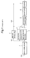
- Fig. 1 is a block diagram showing the structure of an embodiment of "High Efficiency Image Coding System" described in the Japanese Patent Public Disclosure No. 1688/1991.
- the coding system includes a non-interlacing section 1, a motion detecting section 2, a non-interlace blocking section 3, an individual field blocking section 4, an orthogonal transform section 5, a quantizing section 6 for quantizing a conversion coefficient at the output of the orthogonal transform section 5, and coding section 7.
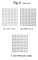
- a series of input image signals 100 which are produced by the interlaced scanning method and applied to each field, are converted to a non-interlaced signal 101 in the non-interlacing section 1 as indicated in Fig. 2(C).
- the pixels belonging to the odd field and the pixels belonging to the even field appear alternately in every other line.
- FIG. 3(A) shows an example of such a condition.
- the correlation between adjacent lines is lowered and it is considered to be effective to execute the coding in units of individual fields. This is because a non-interlaced signal is used for the moving object results in discontinuation as shown in Fig. 3(B), causing a power to be generated in high frequency coefficients during the transform coding. In this case, the blocking as indicated in Fig. 3(C) is adequate.
- the motion detector 2 detects the motion of an object and changes the operation when the object is detected as being stationary by a signal 103 indicating motion, to conduct the blocking shown in Fig. 3(A) (hereinafter, this arrangement of Fig. 3(A) is called the non-interlace blocking) in the non-interlace blocking circuit 3. If the object is detected to be moving, the motion detector 2 changes the operation to conduct the blocking shown in Fig. 3(C) (hereinafter, this arrangement of Fig. 3(C) is called the individual field blocking) in the individual field blocking circuit 4.
- the blocks obtained by changing the blocking as explained above are subjected to the discrete cosine transformation (DCT) in the orthogonal transform section 5.
- DCT discrete cosine transformation
- the transform coefficients obtained as described above are quantized in the quantizing section 6, and a variable length code is assigned in the coding section 7 in accordance with the occurrence probability of respective events.
- US-A-4 849 812 already discloses a television system in which digitalized picture signals subjected to a transform coding are transmitted from an encoding station to a decoding station. In order to detect motion effects between the two fields of a picture, these fields are examined in a motion detector. If no motion ist detected, intraframe transform is employed, and if motion is detected, intrafield transform is employed. Small motion effects can be eliminated by subjecting the picture signal to a median filtering before subjecting it to an intraframe transform.
- the present invention has been proposed to overcome the problems in the prior art. Therefore it is an object of the present invention not only to adaptively discriminate between a block which is effective for non-interlace blocking and a block which is effective for individual field blocking, but also to enhance coding efficiency by adding a class of blocking so that field correlation is used even for a moving image, the quantization accuracy is controlled and the scanning sequence of transform coeffecients is changed in accordance with switching of the blocking.
- an adaptive blocking image coding system comprises the features of claim 1. Specific embodiments of the system according to the invention are defined in the claims.
- an adaptive blocking image coding system encodes an input image signal obtained by interlaced scanning in a unit of the block of M pixels x N lines. More specifically, the adaptive blocking image coding system comprises blocking means for selectively forming a first type block including only the pixels of M pixels x N lines belonging to the odd field of the input image signal or the pixels of M pixels x N lines belonging to the even field of the input image signal, a second type block wherein the pixels of the M pixels x N/2 lines belonging to the odd field and the M pixels x N/2 lines belonging to the even field are arranged alternately in every other line corresponding to scanning positions on a display screen, a third type block wherein the pixels of M pixels x N/2 lines belonging to the odd field are arranged in the upper or lower half of the block and the pixels of M pixels x N/2 lines belonging to the even field are arranged in the remaining half of the block, and a fourth type block wherein the pixels of M pixels x N/2 lines belonging to the odd field are arranged in the upper of lower half
- the system further includes blocking determining means for determining the selected type of block formed by the blocking means, a transform means for orthogonally transforming the selected block formed by the blocking means, quantizing means for quantizing the transform coefficient obtained by the transform means, and coding means for encoding the quantized index obtained by the quantizing means.
- the block of the M pixels x N lines if obtained by one blocking selected from the non-interlace blocking where the pixels of M pixels x N/2 lines belonging to the odd field and the pixels of M pixels x N/2 lines belonging to the even field are arranged in every other line corresponding to the scanning positions on the display screen, an arrangement (hereinafter, called split blocking) where the pixels of M pixels x N/2 lines belonging to the odd number field are arranged in the upper half or lower half block and the pixels of M pixels x N/2 lines belonging to the even field are arranged in the remaining half block, and an arrangement (hereinafter, called inverted split blocking) where the pixels of M pixels x N/2 lines belonging to the odd field are arranged in the upper or lower half block, the pixels of M pixels x N/2 lines belonging to the even field are arranged in the remaining half block and the pixels of either field are inverted in the vertical direction with respect to the display screen.
- split blocking an arrangement where the pixels of M pixels x N/2 lines belonging to the odd number field are arranged in the upper half or lower
- the quantizing means for quantizing the transform coefficient in the adaptive blocking image coding system variably controls the quantization accuracy in accordance with the type of arrangement provided by the blocking means.
- one of the arrangements including individual field blocking, non-interlace blocking, split blocking, or inverted split blocking is orthogonally transformed, the transform coefficient is quantized and the quantizing index is encoded with the quantizing accuracy in accordance with the information, indicating the selected blocking.
- the coding means for encoding the quantized index obtained by quantizing the transform coefficient determines the scanning sequence (path) of quantizing the transform coefficient in accordance with the type of arrangement to be blocked by the blocking means.
- one of the arrangements to be blocking-processed by the individual field blocking, non-interlace blocking, split blocking, or inverted split blocking is orthogonally transformed, the transform coefficient is quantized, and the quantizing index is encoded with the quantization accuracy and the scanning sequence in accordance with the information indicating the selected blocking.
- the blocking determining means determines the type of arrangement to be blocked in the blocking means in accordance with a value obtained by multiplying a predetermined weighting coefficient with the pixels of each line included in the block and then totaling the multiplied values.
- one of the arrangements to be blocking-processed by individual field blocking, non-interlace blocking, split blocking, or inverted split blocking is selected by the value obtained by multiplying the predetermined weighting coefficient with the pixels of each line included in the block and then totaling such multiplied values.
- the selected block is orthogonally transformed, the transform coefficient is quantized and the quantizing index is encoded.
- the blocking determining means determines the type of arrangement having the minimum coefficient power of a predetermined high frequency component among the transform coefficients obtained by discrete cosine transform of the block.
- one of the arrangements to be blocking-processed by individual field blocking, non-interlace blocking, split blocking, or inverted split blocking is selected in such a manner that the coefficient power of the predetermined high frequency element component is the minimum among the transform coefficients obtained by discrete cosine transform of the block.
- the determined block is orthogonally transformed, the transform coefficient is quantized, and the quantizing index is encoded.
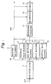
- the image coding system comprises a non-interlacing section 1 for conducting non-interlace processing; a blocking determination section 8; an individual field blocking section 4; a non-interlace blocking section 3; a split blocking section 9; an inverted split blocking section 10; an orthogonal transform section 11; a quantizing section 12 and coding section 13.
- Figs. 5A - 5D show individual field blocking non-interlace blocking, split blocking and inverted split blocking, respectively.
- the operation will be explained with reference to Fig. 4 and Figs. 5A - 5D.
- the input image signal series 100 which is scanned by the interlace scanning method and is inputted field by field is converted into a non-interlaced signal 101 in the non-interlace section 1.
- Fig. 2 shows a profile of non-interlace processing in the prior art similar to the non-interlace processing in the present invention.
- (A) is defined as an input image signal from the odd field and (B) as an input image signal of the even field
- the non-interlaced signal 101 shown in (c) alternately combining the lines from respective fields, can be obtained.
- the individual field blocking section 4 executes, as shown in Fig. 5(A), blocking in which the fields are processed individually. This blocking is effective when the correlation between the fields is not available because of quick motion.
- the non-interlace blocking section 3 executes the blocking shown in Fig. 5(B).
- a continuous image can be obtained by non-interlaced processing of the fields.
- the wavelength of the signal thereby becomes substantially longer, resulting in power being concentrated on low frequency components in the successive transform coding.
- the split blocking section 9 conducts the blocking as shown in Fig. 5(C). This blocking is effective in the case where the correlation between the fields exists but the fields are noncontinuous when non-interlace blocking is carried out.
- the inverted split blocking section 10 conducts the blocking shown in Fig. 5(D). This blocking is also effective in the case where the correlation between fields exists but the fields are noncontinuous when non-interlace blocking is carried out. This blocking prevents discontinuation at the center of the block when the split blocking method is used.
- the blocking determinating section 8 determines the optimum blocking from a plurality of blockings as explained above and outputs a blocking arrangement selecting signal 102 for selecting the determined blocking.
- a blocking arrangement selecting signal 102 for selecting the determined blocking.
- it is important to enhance the concentration of power, on the low frequency coefficients in the transform coding. For this purpose, it is effective to evaluate the amplitude of high frequency components in each blocking and select the blocking having the minimum amplitude.
- a weight is multiplied with the pixels of each line and the obtained values are then totaled. For example, the weight of +1 is given to the lines 0, 2, 4, 6 using the line numbers shown in Fig. 5, and the weight of -1 is given to the lines 1, 3, 5, 7. Thereafter, the obtained values are totaled to obtain the absolute value of the sum. Moreover, the weight +1 is given to the lines 8, 10, 12, 14, and the weight -1 is given to the lines 9, 11, 13, 15. The obtained values are then totaled to also obtain the absolute values of the sum. Both absolute values are totaled. Thus, the weighting is inverted alternately for respective lines and it is equivalent to the evaluation of the maximum frequency component when non-interlace blocking has been conducted.
- the weight +1 is given to the lines 0, 4, 8, 12 and the weight -1 to the lines 2, 6, 10, 14. The obtained values are totaled to obtain the absolute value of the sum. In addition, the weight +1 is given to the lines 1, 5, 9, 13 and the weight -1 to the lines 3, 7, 11, 15. The obtained values are then totaled to obtain the absolute value of the sum. These absolute values are also totaled to evaluate the maximum frequency component of the individual field blocking.
- the weight +1 is given to the lines 0, 4, 1, 5 and the weight -1 to the lines 2, 6, 3, 7. The obtained values are totaled to obtain the absolute value of the sum.
- the weight +1 is also given to the lines 8, 12, 9, 13 and the weight -1 to the lines 10, 14, 11, 15. The obtained values are totaled to obtain the absolute value of the sum. Both absolute values are then totaled to evaluate the maximum frequency component of the split blocking.
- the weight +1 is given to the lines 0, 4, 7, 3 and the weight -1 to the lines 2, 6, 5, 1.
- the obtained values are totaled to obtain the absolute value of the sum.
- the weight +1 is given to the lines 8, 12, 15, 11 and the weight -1 to the lines 10, 14, 13, 9.
- the obtained values are totaled to obtain the absolute value of the sum.
- the number of orthogonal transformed coefficients having an amplitude larger than a predetermined threshold value for the respective blockings is counted, and the blocking having the minimum number is selected.
- the orthogonal transform section 11 carried out the orthogonal transform of the selected block to obtain the transform coefficients.
- the obtained transform coefficients are quantized in a fixed sequence by the quantizing section 12. In this case, some difference lies in the power of the coefficients depending on the type of blocking. In general, non-interlace blocking tends to be selected for a stationary region and the power is comparatively small.
- split blocking and inverted split blocking are considered to be intermediate to the above two blockings. Therefore, efficiency can be improved by variably controlling quantization accuracy in accordance with the type of blocking.
- the quantizing accuracy can also be controlled variably in accordance with not only the type of blocking but also the combination of actual signal power and quantization error power. In this case, it is also possible to execute variable length coding by combining the information indicating type of blocking and the information indicating quantization accuracy.
- Indexes obtained by quantizing the coefficients are encoded in the coding section 13.
- the coefficients are scanned from those having a larger coefficient power to those having a smaller one in order to enhance the efficiency of encoding.
- the encoding may cease. Therefore, it is very convenient if the power distribution can be anticipated. There is a tendency with respect to the distribution of power of the coefficients that the power is increased as the frequency is lower.
- the blocking is adaptively changing, as in the present invention, the coefficients having lower power do not always correspond to low frequency components. Then, the coding efficiency can be improved by changing the scanning sequence or path in accordance with the type of blocking.
- the coding efficiency of transform coding is improved by switching the blocking of an image signal scanned by the interlaced scanning method into an adapted blocking. Moreover, the efficient assignment of information quantity can be realized by variably controlling the quantizing accuracy of transform coefficients correspondingly to the switching of the blocking. In addition, the encoding efficiency can also be improved in transform coding by changing the scanning sequence of the transform coefficients within the block.
Abstract
Description
- The present invention relates to an adaptive blocking image coding system according to the pre-characterizing part of
claim 1. - As is known in the art, means for eliminating redundant components included in an image signal is used for coding an image signal. A typical approach to image coding is the transform coding method wherein an image is divided into blocks, an orthogonal transform is carried out for each of the blocks, and the transform coefficients are encoded.
- In the case of television signals such as an NTSC signal, interlaced scanning is used whereby an image signal of one frame is scanned twice, once in the odd field and once in the even field. The two fields scan different but complementary spaces of an image. The fields have image information at different times but there is a relatively strong correlation therebetween because the scanned lines of the two fields are alternate and adjacent. There is a technique in which coding is carried out after combining the fields and dividing them into blocks when coding an image signal produced by the interlaced scanning.
- Fig. 1 is a block diagram showing the structure of an embodiment of "High Efficiency Image Coding System" described in the Japanese Patent Public Disclosure No. 1688/1991. In Fig. 1, the coding system includes a
non-interlacing section 1, amotion detecting section 2, anon-interlace blocking section 3, an individualfield blocking section 4, anorthogonal transform section 5, a quantizingsection 6 for quantizing a conversion coefficient at the output of theorthogonal transform section 5, andcoding section 7. - In operation, a series of
input image signals 100, which are produced by the interlaced scanning method and applied to each field, are converted to anon-interlaced signal 101 in thenon-interlacing section 1 as indicated in Fig. 2(C). As shown, the pixels belonging to the odd field and the pixels belonging to the even field appear alternately in every other line. - When an object is stationary and the correlation between adjacent lines is high, it is effective to use a non-interlaced signal and to code the image signal in a block including components from both fields. Fig. 3(A) shows an example of such a condition. On the other hand, when an object is moving, the correlation between adjacent lines is lowered and it is considered to be effective to execute the coding in units of individual fields. This is because a non-interlaced signal is used for the moving object results in discontinuation as shown in Fig. 3(B), causing a power to be generated in high frequency coefficients during the transform coding. In this case, the blocking as indicated in Fig. 3(C) is adequate.
- Thus, the
motion detector 2 detects the motion of an object and changes the operation when the object is detected as being stationary by asignal 103 indicating motion, to conduct the blocking shown in Fig. 3(A) (hereinafter, this arrangement of Fig. 3(A) is called the non-interlace blocking) in thenon-interlace blocking circuit 3. If the object is detected to be moving, themotion detector 2 changes the operation to conduct the blocking shown in Fig. 3(C) (hereinafter, this arrangement of Fig. 3(C) is called the individual field blocking) in the individualfield blocking circuit 4. - The blocks obtained by changing the blocking as explained above are subjected to the discrete cosine transformation (DCT) in the
orthogonal transform section 5. The transform coefficients obtained as described above are quantized in the quantizingsection 6, and a variable length code is assigned in thecoding section 7 in accordance with the occurrence probability of respective events. - Since a conventional image coding system has been structured as described above, it has been difficult to realize the blocking utilizing the correlation between fields when an object is moving. Moreover, such a system has not utilized the property of different intensities in power distribution of the coefficients after conversion caused by the difference in arrangement of pixels within the block. In addition, there is the difference in power between the stationary blocks and moving blocks, the moving blocks having a high signal power which has not been utilized.
- US-A-4 849 812 already discloses a television system in which digitalized picture signals subjected to a transform coding are transmitted from an encoding station to a decoding station. In order to detect motion effects between the two fields of a picture, these fields are examined in a motion detector. If no motion ist detected, intraframe transform is employed, and if motion is detected, intrafield transform is employed. Small motion effects can be eliminated by subjecting the picture signal to a median filtering before subjecting it to an intraframe transform.
- The present invention has been proposed to overcome the problems in the prior art. Therefore it is an object of the present invention not only to adaptively discriminate between a block which is effective for non-interlace blocking and a block which is effective for individual field blocking, but also to enhance coding efficiency by adding a class of blocking so that field correlation is used even for a moving image, the quantization accuracy is controlled and the scanning sequence of transform coeffecients is changed in accordance with switching of the blocking.
- In order to solve this object, an adaptive blocking image coding system comprises the features of
claim 1. Specific embodiments of the system according to the invention are defined in the claims. - According to the present invention, an adaptive blocking image coding system encodes an input image signal obtained by interlaced scanning in a unit of the block of M pixels x N lines. More specifically, the adaptive blocking image coding system comprises blocking means for selectively forming a first type block including only the pixels of M pixels x N lines belonging to the odd field of the input image signal or the pixels of M pixels x N lines belonging to the even field of the input image signal, a second type block wherein the pixels of the M pixels x N/2 lines belonging to the odd field and the M pixels x N/2 lines belonging to the even field are arranged alternately in every other line corresponding to scanning positions on a display screen, a third type block wherein the pixels of M pixels x N/2 lines belonging to the odd field are arranged in the upper or lower half of the block and the pixels of M pixels x N/2 lines belonging to the even field are arranged in the remaining half of the block, and a fourth type block wherein the pixels of M pixels x N/2 lines belonging to the odd field are arranged in the upper of lower half of the block, the pixels of M pixels x N/2 lines belonging to the even field are arranged in the remaining half of the block and the pixels of either field are inverted upside down in the vertical direction with respect to the display screen. The system further includes blocking determining means for determining the selected type of block formed by the blocking means, a transform means for orthogonally transforming the selected block formed by the blocking means, quantizing means for quantizing the transform coefficient obtained by the transform means, and coding means for encoding the quantized index obtained by the quantizing means.
- With the structure described above, the block of the M pixels x N lines if obtained by one blocking selected from the non-interlace blocking where the pixels of M pixels x N/2 lines belonging to the odd field and the pixels of M pixels x N/2 lines belonging to the even field are arranged in every other line corresponding to the scanning positions on the display screen, an arrangement (hereinafter, called split blocking) where the pixels of M pixels x N/2 lines belonging to the odd number field are arranged in the upper half or lower half block and the pixels of M pixels x N/2 lines belonging to the even field are arranged in the remaining half block, and an arrangement (hereinafter, called inverted split blocking) where the pixels of M pixels x N/2 lines belonging to the odd field are arranged in the upper or lower half block, the pixels of M pixels x N/2 lines belonging to the even field are arranged in the remaining half block and the pixels of either field are inverted in the vertical direction with respect to the display screen. The obtained block is orthogonally transformed the transform coefficients are quantized, and then the quantization index is encoded.
- According to an embodiment of the present invention, the quantizing means for quantizing the transform coefficient in the adaptive blocking image coding system variably controls the quantization accuracy in accordance with the type of arrangement provided by the blocking means.
- More specifically, one of the arrangements including individual field blocking, non-interlace blocking, split blocking, or inverted split blocking is orthogonally transformed, the transform coefficient is quantized and the quantizing index is encoded with the quantizing accuracy in accordance with the information, indicating the selected blocking.
- According to another embodiment of the present invention, the coding means for encoding the quantized index obtained by quantizing the transform coefficient determines the scanning sequence (path) of quantizing the transform coefficient in accordance with the type of arrangement to be blocked by the blocking means.
- More specifically, one of the arrangements to be blocking-processed by the individual field blocking, non-interlace blocking, split blocking, or inverted split blocking is orthogonally transformed, the transform coefficient is quantized, and the quantizing index is encoded with the quantization accuracy and the scanning sequence in accordance with the information indicating the selected blocking.
- According to a further embodiment of the present invention, the blocking determining means determines the type of arrangement to be blocked in the blocking means in accordance with a value obtained by multiplying a predetermined weighting coefficient with the pixels of each line included in the block and then totaling the multiplied values.
- More particularly, one of the arrangements to be blocking-processed by individual field blocking, non-interlace blocking, split blocking, or inverted split blocking is selected by the value obtained by multiplying the predetermined weighting coefficient with the pixels of each line included in the block and then totaling such multiplied values. The selected block is orthogonally transformed, the transform coefficient is quantized and the quantizing index is encoded.
- According of a still further embodiment of the present invention, the blocking determining means determines the type of arrangement having the minimum coefficient power of a predetermined high frequency component among the transform coefficients obtained by discrete cosine transform of the block.
- In other words, one of the arrangements to be blocking-processed by individual field blocking, non-interlace blocking, split blocking, or inverted split blocking is selected in such a manner that the coefficient power of the predetermined high frequency element component is the minimum among the transform coefficients obtained by discrete cosine transform of the block. The determined block is orthogonally transformed, the transform coefficient is quantized, and the quantizing index is encoded.
- The invention will be more fully understood from the following detailed description and the accompanying drawings in which:
- Fig. 1
- is a block diagram of an image coding system in the prior art;
- Fig. 2
- is a diagram for explaining non-interlace blocking;
- Fig. 3
- is a diagram for explaining an adaptive blocking of the prior art;
- Fig. 4
- is a block diagram of an embodiment of the present invention; and
- Fig. 5
- is a diagram for explaining adaptive blocking in the embodiment shown in Fig. 4.
- Referring to Fig. 4, an embodiment of the present invention is shown as an adaptive blocking image coding system. In Fig. 4, the image coding system comprises a
non-interlacing section 1 for conducting non-interlace processing; ablocking determination section 8; an individualfield blocking section 4; anon-interlace blocking section 3; asplit blocking section 9; an invertedsplit blocking section 10; anorthogonal transform section 11; a quantizingsection 12 andcoding section 13. Such various types of blocking are shown in Fig. 5. Figs. 5A - 5D show individual field blocking non-interlace blocking, split blocking and inverted split blocking, respectively. - The operation will be explained with reference to Fig. 4 and Figs. 5A - 5D. The input
image signal series 100 which is scanned by the interlace scanning method and is inputted field by field is converted into anon-interlaced signal 101 in thenon-interlace section 1. - Fig. 2 shows a profile of non-interlace processing in the prior art similar to the non-interlace processing in the present invention. When (A) is defined as an input image signal from the odd field and (B) as an input image signal of the even field, the
non-interlaced signal 101 shown in (c), alternately combining the lines from respective fields, can be obtained. - The individual
field blocking section 4 executes, as shown in Fig. 5(A), blocking in which the fields are processed individually. This blocking is effective when the correlation between the fields is not available because of quick motion. - The
non-interlace blocking section 3 executes the blocking shown in Fig. 5(B). In the case of a stationary or still image, a continuous image can be obtained by non-interlaced processing of the fields. The wavelength of the signal thereby becomes substantially longer, resulting in power being concentrated on low frequency components in the successive transform coding. - The
split blocking section 9 conducts the blocking as shown in Fig. 5(C). This blocking is effective in the case where the correlation between the fields exists but the fields are noncontinuous when non-interlace blocking is carried out. - The inverted
split blocking section 10 conducts the blocking shown in Fig. 5(D). This blocking is also effective in the case where the correlation between fields exists but the fields are noncontinuous when non-interlace blocking is carried out. This blocking prevents discontinuation at the center of the block when the split blocking method is used. - The blocking
determinating section 8 determines the optimum blocking from a plurality of blockings as explained above and outputs a blockingarrangement selecting signal 102 for selecting the determined blocking. Here, it is important to enhance the concentration of power, on the low frequency coefficients in the transform coding. For this purpose, it is effective to evaluate the amplitude of high frequency components in each blocking and select the blocking having the minimum amplitude. - In one of the evaluation methods, a weight is multiplied with the pixels of each line and the obtained values are then totaled. For example, the weight of +1 is given to the
lines lines lines lines - Further, the weight +1 is given to the
lines lines lines lines - In addition, the weight +1 is given to the
lines lines lines lines - The weight +1 is given to the
lines lines lines lines - In another method for evaluation of each blocking, the number of orthogonal transformed coefficients having an amplitude larger than a predetermined threshold value for the respective blockings is counted, and the blocking having the minimum number is selected.
- The
orthogonal transform section 11 carried out the orthogonal transform of the selected block to obtain the transform coefficients. The obtained transform coefficients are quantized in a fixed sequence by the quantizingsection 12. In this case, some difference lies in the power of the coefficients depending on the type of blocking. In general, non-interlace blocking tends to be selected for a stationary region and the power is comparatively small. - Meanwhile, since the correlation between fields becomes small in a quick motion area, individual field blocking is often selected and the power is large. Moreover, split blocking and inverted split blocking are considered to be intermediate to the above two blockings. Therefore, efficiency can be improved by variably controlling quantization accuracy in accordance with the type of blocking.
- The quantizing accuracy can also be controlled variably in accordance with not only the type of blocking but also the combination of actual signal power and quantization error power. In this case, it is also possible to execute variable length coding by combining the information indicating type of blocking and the information indicating quantization accuracy.
- Indexes obtained by quantizing the coefficients are encoded in the
coding section 13. In this case, the coefficients are scanned from those having a larger coefficient power to those having a smaller one in order to enhance the efficiency of encoding. For the coefficients having a power lower than a certain specified value, the encoding may cease. Therefore, it is very convenient if the power distribution can be anticipated. There is a tendency with respect to the distribution of power of the coefficients that the power is increased as the frequency is lower. However, if the blocking is adaptively changing, as in the present invention, the coefficients having lower power do not always correspond to low frequency components. Then, the coding efficiency can be improved by changing the scanning sequence or path in accordance with the type of blocking. - Since the present invention is structured as explained above, the following effects can be obtained.
- The coding efficiency of transform coding is improved by switching the blocking of an image signal scanned by the interlaced scanning method into an adapted blocking. Moreover, the efficient assignment of information quantity can be realized by variably controlling the quantizing accuracy of transform coefficients correspondingly to the switching of the blocking. In addition, the encoding efficiency can also be improved in transform coding by changing the scanning sequence of the transform coefficients within the block.
Claims (5)
- An adaptive image block coding system for encoding an input image signal (100) obtained by interlaced scanning in block units of M pixels x N lines, comprising:characterized in that the block forming means is adapted to selectively form also a third type of blocks (9) wherein the pixels of M pixels x N/2 lines belonging to the odd field are arranged in the upper or lower half of the block and the pixels of M pixels x N/2 lines belonging to the even field are arranged in the remaining half of the block, and a fourth type of blocks (10) wherein the pixels of M pixels x N/2 lines belonging to the odd field are arranged in the upper or lower half of the block, the pixels of M pixels x N/2 lines belonging to the even field are arranged in the remaining half of the block and the pixels of either field are inverted upside down in the vertical direction with respect to the display screen.block forming means for selectively forming a first type of blocks (4) including only the pixels of M pixels x N lines belonging to the odd field of the input image signal (100) or the pixels of M pixels x N lines belonging to the even field of the input image signal (100), and a second type of blocks (3) wherein the pixels of the M pixels x N/2 lines belonging to the odd field and the pixels of the M pixels x N/2 lines belonging to the even field are arranged alternately in every other line corresponding to scanning positions on a display screen,block type determining means (8) for determining the selected type of block formed by said block forming means,transform means (11) for orthogonally transforming the selected block formed by said block forming means, quantizing means (12) for quantizing a transform coefficient obtained by said transform means (11), andcoding means (13) for encoding a quantized index obtained by said quantizing means,
- An adaptive image block coding system according to Claim 1 wherein said quantizing means (12) for quantizing the transform coefficient variably controls the quantization accuracy in accordance with the type of arrangement provided by said block forming means (3,4,9,10).
- An adaptive image block coding system according to Claim 2 wherein said coding means (13) for encoding the quantized index obtained by quantizing said transform coefficient determines the scanning sequence of quantizing the transform coefficient in accordance with the type of arrangement to be blocked by said block forming means (3,4,9,10).
- An adaptive blocking image coding system according to Claim 2 wherein said block type determining means is adapted to (8) determine the type of arrangement to be blocked in said block forming means (3,4,9,10) in accordance with a value obtained by multiplying a predetermined weighting coefficient with the pixels of each line including in the block and then totaling the multiplied values.
- An adaptive blocking image coding system according to Claim 2 wherein said block type determining means is adapted to (8) determine the type of arrangement having the minimum coefficient power of a predetermined highfrequency component among the transform coefficients obtained by a discrete cosine transform of the block.
Priority Applications (5)
| Application Number | Priority Date | Filing Date | Title |
|---|---|---|---|
| EP19990124382 EP0986263A3 (en) | 1991-10-22 | 1992-10-21 | Predictive video coding system |
| EP19990124384 EP0984636B1 (en) | 1991-10-22 | 1992-10-21 | Predictive video coding system |
| EP19990124383 EP0984635B1 (en) | 1991-10-22 | 1992-10-21 | Predictive video coding system |
| EP19970113971 EP0825780B1 (en) | 1991-10-22 | 1992-10-21 | Coding system |
| EP20000127405 EP1091589B1 (en) | 1991-10-22 | 1992-10-21 | Coding system |
Applications Claiming Priority (4)
| Application Number | Priority Date | Filing Date | Title |
|---|---|---|---|
| JP273843/91 | 1991-10-22 | ||
| JP27384391A JP2586260B2 (en) | 1991-10-22 | 1991-10-22 | Adaptive blocking image coding device |
| JP80654/92 | 1992-04-02 | ||
| JP8065492A JP2924431B2 (en) | 1991-10-22 | 1992-04-02 | Coding method |
Related Child Applications (2)
| Application Number | Title | Priority Date | Filing Date |
|---|---|---|---|
| EP20000127405 Division EP1091589B1 (en) | 1991-10-22 | 1992-10-21 | Coding system |
| EP19970113971 Division EP0825780B1 (en) | 1991-10-22 | 1992-10-21 | Coding system |
Publications (3)
| Publication Number | Publication Date |
|---|---|
| EP0538834A2 EP0538834A2 (en) | 1993-04-28 |
| EP0538834A3 EP0538834A3 (en) | 1994-04-20 |
| EP0538834B1 true EP0538834B1 (en) | 1999-05-19 |
Family
ID=26421636
Family Applications (7)
| Application Number | Title | Priority Date | Filing Date |
|---|---|---|---|
| EP19990124383 Expired - Lifetime EP0984635B1 (en) | 1991-10-22 | 1992-10-21 | Predictive video coding system |
| EP03000329A Revoked EP1309202B8 (en) | 1991-10-22 | 1992-10-21 | Video coding system |
| EP19990124384 Expired - Lifetime EP0984636B1 (en) | 1991-10-22 | 1992-10-21 | Predictive video coding system |
| EP19990124382 Withdrawn EP0986263A3 (en) | 1991-10-22 | 1992-10-21 | Predictive video coding system |
| EP19970113971 Expired - Lifetime EP0825780B1 (en) | 1991-10-22 | 1992-10-21 | Coding system |
| EP20000127405 Expired - Lifetime EP1091589B1 (en) | 1991-10-22 | 1992-10-21 | Coding system |
| EP19920118018 Expired - Lifetime EP0538834B1 (en) | 1991-10-22 | 1992-10-21 | Image signal coding system |
Family Applications Before (6)
| Application Number | Title | Priority Date | Filing Date |
|---|---|---|---|
| EP19990124383 Expired - Lifetime EP0984635B1 (en) | 1991-10-22 | 1992-10-21 | Predictive video coding system |
| EP03000329A Revoked EP1309202B8 (en) | 1991-10-22 | 1992-10-21 | Video coding system |
| EP19990124384 Expired - Lifetime EP0984636B1 (en) | 1991-10-22 | 1992-10-21 | Predictive video coding system |
| EP19990124382 Withdrawn EP0986263A3 (en) | 1991-10-22 | 1992-10-21 | Predictive video coding system |
| EP19970113971 Expired - Lifetime EP0825780B1 (en) | 1991-10-22 | 1992-10-21 | Coding system |
| EP20000127405 Expired - Lifetime EP1091589B1 (en) | 1991-10-22 | 1992-10-21 | Coding system |
Country Status (14)
| Country | Link |
|---|---|
| US (13) | US5274442A (en) |
| EP (7) | EP0984635B1 (en) |
| JP (2) | JP2586260B2 (en) |
| KR (1) | KR950011197B1 (en) |
| AT (3) | ATE236492T1 (en) |
| AU (2) | AU652490B2 (en) |
| CA (4) | CA2081065C (en) |
| DE (6) | DE69233167T2 (en) |
| DK (6) | DK0984635T3 (en) |
| ES (6) | ES2136070T3 (en) |
| FI (5) | FI111591B (en) |
| HK (5) | HK1009223A1 (en) |
| NO (2) | NO310849B1 (en) |
| SG (1) | SG65597A1 (en) |
Families Citing this family (131)
| Publication number | Priority date | Publication date | Assignee | Title |
|---|---|---|---|---|
| JP2586260B2 (en) * | 1991-10-22 | 1997-02-26 | 三菱電機株式会社 | Adaptive blocking image coding device |
| JP3165296B2 (en) * | 1992-12-25 | 2001-05-14 | 三菱電機株式会社 | Inter-frame coding processing method, inter-frame coding processing method, and coding control method |
| US5915040A (en) * | 1993-03-29 | 1999-06-22 | Canon Kabushiki Kaisha | Image processing apparatus |
| BE1007252A3 (en) * | 1993-06-29 | 1995-05-02 | Philips Electronics Nv | Motion compensator. |
| JPH0787448A (en) * | 1993-06-30 | 1995-03-31 | Victor Co Of Japan Ltd | Coding circuit and decoding circuit for digital video signal |
| JP3202433B2 (en) * | 1993-09-17 | 2001-08-27 | 株式会社リコー | Quantization device, inverse quantization device, image processing device, quantization method, inverse quantization method, and image processing method |
| FR2711879B1 (en) * | 1993-10-22 | 1995-12-15 | Thomson Csf | Interframe coding method and device with rate control for recording images on a VCR. |
| US6243139B1 (en) * | 1993-12-22 | 2001-06-05 | Canon Kabushiki Kaisha | Apparatus for block-encoding input image signals |
| TW283289B (en) * | 1994-04-11 | 1996-08-11 | Gen Instrument Corp | |
| US5719961A (en) * | 1994-07-22 | 1998-02-17 | Apple Computer, Inc. | Adaptive technique for encoder and decoder signal transformation |
| JPH0865681A (en) * | 1994-08-25 | 1996-03-08 | Sony Corp | Motion vector detector and motion compensating prediction encoding system using the detector |
| US5596376A (en) * | 1995-02-16 | 1997-01-21 | C-Cube Microsystems, Inc. | Structure and method for a multistandard video encoder including an addressing scheme supporting two banks of memory |
| US5774593A (en) * | 1995-07-24 | 1998-06-30 | University Of Washington | Automatic scene decomposition and optimization of MPEG compressed video |
| JP2962348B2 (en) * | 1996-02-08 | 1999-10-12 | 日本電気株式会社 | Image code conversion method |
| US6542642B2 (en) * | 1996-02-29 | 2003-04-01 | Canon Kabushiki Kaisha | Image coding process and motion detecting process using bidirectional prediction |
| JP3111028B2 (en) * | 1996-03-14 | 2000-11-20 | 松下電器産業株式会社 | Image signal processing apparatus and image signal processing method |
| CN1216199A (en) | 1997-01-30 | 1999-05-05 | 松下电器产业株式会社 | Digital image replenishment method, image processing device and data recording medium |
| JPH10234014A (en) * | 1997-02-20 | 1998-09-02 | Matsushita Electric Ind Co Ltd | Image decoding method, image decoder, image multiplexing method, image multiplexer and recording medium |
| JPH10262244A (en) * | 1997-03-18 | 1998-09-29 | Fujitsu Ltd | Still image coder |
| JP3604864B2 (en) * | 1997-04-25 | 2004-12-22 | シャープ株式会社 | Video encoding device |
| US6108383A (en) * | 1997-07-15 | 2000-08-22 | On2.Com, Inc. | Method and apparatus for compression and decompression of video images |
| JPH11122613A (en) * | 1997-10-16 | 1999-04-30 | Matsushita Electric Ind Co Ltd | Video signal processor and video signal processing method |
| US5973743A (en) * | 1997-12-02 | 1999-10-26 | Daewoo Electronics Co., Ltd. | Mode coding method and apparatus for use in an interlaced shape coder |
| US20020044692A1 (en) * | 2000-10-25 | 2002-04-18 | Goertzen Kenbe D. | Apparatus and method for optimized compression of interlaced motion images |
| EP1062626A4 (en) | 1998-02-13 | 2004-10-06 | Quvis Inc | Apparatus and method for optimized compression of interlaced motion images |
| US6408029B1 (en) | 1998-04-02 | 2002-06-18 | Intel Corporation | Method and apparatus for simplifying real-time data encoding |
| US6904174B1 (en) * | 1998-12-11 | 2005-06-07 | Intel Corporation | Simplified predictive video encoder |
| US7046734B2 (en) * | 1998-04-02 | 2006-05-16 | Intel Corporation | Method and apparatus for performing real-time data encoding |
| US6999047B1 (en) * | 1998-08-12 | 2006-02-14 | Koninklijke Philips Electronics N.V. | Displaying video on a plasma display panel |
| US6243140B1 (en) * | 1998-08-24 | 2001-06-05 | Hitachi America, Ltd | Methods and apparatus for reducing the amount of buffer memory required for decoding MPEG data and for performing scan conversion |
| KR20000021867A (en) * | 1998-09-30 | 2000-04-25 | 전주범 | Method for encoding motion vector of binary form signal |
| US6983018B1 (en) | 1998-11-30 | 2006-01-03 | Microsoft Corporation | Efficient motion vector coding for video compression |
| US20030185455A1 (en) * | 1999-02-04 | 2003-10-02 | Goertzen Kenbe D. | Digital image processor |
| US20030142875A1 (en) * | 1999-02-04 | 2003-07-31 | Goertzen Kenbe D. | Quality priority |
| US6499060B1 (en) | 1999-03-12 | 2002-12-24 | Microsoft Corporation | Media coding for loss recovery with remotely predicted data units |
| DE10035109B4 (en) * | 1999-07-20 | 2012-03-08 | Lg Information & Communications, Ltd. | Terminal and method for transporting still images |
| EP1081959B1 (en) * | 1999-09-03 | 2007-11-14 | STMicroelectronics S.r.l. | Method for recognizing a progressive or an interlaced content in a video sequence |
| US6633612B2 (en) * | 2000-12-13 | 2003-10-14 | Genesis Microchip Inc. | Method and apparatus for detecting motion between odd and even video fields |
| FR2832271A1 (en) * | 2001-11-13 | 2003-05-16 | Koninkl Philips Electronics Nv | TUNER INCLUDING A VOLTAGE CONVERTER |
| US7027982B2 (en) * | 2001-12-14 | 2006-04-11 | Microsoft Corporation | Quality and rate control strategy for digital audio |
| US7003035B2 (en) | 2002-01-25 | 2006-02-21 | Microsoft Corporation | Video coding methods and apparatuses |
| US20040001546A1 (en) | 2002-06-03 | 2004-01-01 | Alexandros Tourapis | Spatiotemporal prediction for bidirectionally predictive (B) pictures and motion vector prediction for multi-picture reference motion compensation |
| US7224731B2 (en) * | 2002-06-28 | 2007-05-29 | Microsoft Corporation | Motion estimation/compensation for screen capture video |
| US6980695B2 (en) * | 2002-06-28 | 2005-12-27 | Microsoft Corporation | Rate allocation for mixed content video |
| US7016547B1 (en) * | 2002-06-28 | 2006-03-21 | Microsoft Corporation | Adaptive entropy encoding/decoding for screen capture content |
| US7280700B2 (en) | 2002-07-05 | 2007-10-09 | Microsoft Corporation | Optimization techniques for data compression |
| KR100865034B1 (en) * | 2002-07-18 | 2008-10-23 | 엘지전자 주식회사 | Method for predicting motion vector |
| US7154952B2 (en) | 2002-07-19 | 2006-12-26 | Microsoft Corporation | Timestamp-independent motion vector prediction for predictive (P) and bidirectionally predictive (B) pictures |
| US7822120B2 (en) * | 2002-07-26 | 2010-10-26 | Panasonic Corporation | Moving picture encoding method, moving picture decoding method, and recording medium |
| US7433824B2 (en) | 2002-09-04 | 2008-10-07 | Microsoft Corporation | Entropy coding by adapting coding between level and run-length/level modes |
| ES2334934T3 (en) | 2002-09-04 | 2010-03-17 | Microsoft Corporation | ENTROPY CODIFICATION BY ADAPTATION OF CODIFICATION BETWEEN LEVEL MODES AND SUCCESSION AND LEVEL LENGTH. |
| JP3791922B2 (en) * | 2002-09-06 | 2006-06-28 | 富士通株式会社 | Moving picture decoding apparatus and method |
| KR101011121B1 (en) * | 2002-10-01 | 2011-01-25 | 파나소닉 주식회사 | Picture decoding device, and method using the same |
| JP3960258B2 (en) * | 2003-04-28 | 2007-08-15 | ソニー株式会社 | Signal processing apparatus and signal processing method |
| US7426308B2 (en) | 2003-07-18 | 2008-09-16 | Microsoft Corporation | Intraframe and interframe interlace coding and decoding |
| US20050013498A1 (en) * | 2003-07-18 | 2005-01-20 | Microsoft Corporation | Coding of motion vector information |
| US7499495B2 (en) * | 2003-07-18 | 2009-03-03 | Microsoft Corporation | Extended range motion vectors |
| US7343291B2 (en) | 2003-07-18 | 2008-03-11 | Microsoft Corporation | Multi-pass variable bitrate media encoding |
| US7738554B2 (en) | 2003-07-18 | 2010-06-15 | Microsoft Corporation | DC coefficient signaling at small quantization step sizes |
| US7609763B2 (en) * | 2003-07-18 | 2009-10-27 | Microsoft Corporation | Advanced bi-directional predictive coding of video frames |
| US10554985B2 (en) | 2003-07-18 | 2020-02-04 | Microsoft Technology Licensing, Llc | DC coefficient signaling at small quantization step sizes |
| US7383180B2 (en) | 2003-07-18 | 2008-06-03 | Microsoft Corporation | Constant bitrate media encoding techniques |
| US8085844B2 (en) * | 2003-09-07 | 2011-12-27 | Microsoft Corporation | Signaling reference frame distances |
| US7724827B2 (en) * | 2003-09-07 | 2010-05-25 | Microsoft Corporation | Multi-layer run level encoding and decoding |
| US7567617B2 (en) * | 2003-09-07 | 2009-07-28 | Microsoft Corporation | Predicting motion vectors for fields of forward-predicted interlaced video frames |
| US7782954B2 (en) * | 2003-09-07 | 2010-08-24 | Microsoft Corporation | Scan patterns for progressive video content |
| US7688894B2 (en) * | 2003-09-07 | 2010-03-30 | Microsoft Corporation | Scan patterns for interlaced video content |
| US7577200B2 (en) | 2003-09-07 | 2009-08-18 | Microsoft Corporation | Extended range variable length coding/decoding of differential motion vector information |
| US7317839B2 (en) | 2003-09-07 | 2008-01-08 | Microsoft Corporation | Chroma motion vector derivation for interlaced forward-predicted fields |
| US8064520B2 (en) | 2003-09-07 | 2011-11-22 | Microsoft Corporation | Advanced bi-directional predictive coding of interlaced video |
| US7599438B2 (en) * | 2003-09-07 | 2009-10-06 | Microsoft Corporation | Motion vector block pattern coding and decoding |
| US7577198B2 (en) * | 2003-09-07 | 2009-08-18 | Microsoft Corporation | Number of reference fields for an interlaced forward-predicted field |
| US7570818B2 (en) * | 2003-10-17 | 2009-08-04 | Hewlett-Packard Development Company, L.P. | Method for deblocking and transcoding a media stream |
| KR101187550B1 (en) | 2004-02-27 | 2012-10-04 | 티디비전 코포레이션 에스.에이. 데 씨.브이. | Method and system for digital coding 3d stereoscopic video images |
| CA2557534A1 (en) * | 2004-02-27 | 2005-09-09 | Td Vision Corporation S.A. De C.V. | Method and system for digital decoding 3d stereoscopic video images |
| US8634413B2 (en) | 2004-12-30 | 2014-01-21 | Microsoft Corporation | Use of frame caching to improve packet loss recovery |
| US7693709B2 (en) | 2005-07-15 | 2010-04-06 | Microsoft Corporation | Reordering coefficients for waveform coding or decoding |
| US7684981B2 (en) | 2005-07-15 | 2010-03-23 | Microsoft Corporation | Prediction of spectral coefficients in waveform coding and decoding |
| US7599840B2 (en) | 2005-07-15 | 2009-10-06 | Microsoft Corporation | Selectively using multiple entropy models in adaptive coding and decoding |
| US7565018B2 (en) | 2005-08-12 | 2009-07-21 | Microsoft Corporation | Adaptive coding and decoding of wide-range coefficients |
| US8599925B2 (en) | 2005-08-12 | 2013-12-03 | Microsoft Corporation | Efficient coding and decoding of transform blocks |
| US9077960B2 (en) * | 2005-08-12 | 2015-07-07 | Microsoft Corporation | Non-zero coefficient block pattern coding |
| US7933337B2 (en) | 2005-08-12 | 2011-04-26 | Microsoft Corporation | Prediction of transform coefficients for image compression |
| JP2008118239A (en) * | 2006-11-01 | 2008-05-22 | Canon Inc | Imaging apparatus and control method of imaging apparatus |
| CN101227601B (en) * | 2007-01-15 | 2011-09-14 | 飞思卡尔半导体公司 | Equipment and method for performing geometric transformation in video rendition |
| US8184710B2 (en) | 2007-02-21 | 2012-05-22 | Microsoft Corporation | Adaptive truncation of transform coefficient data in a transform-based digital media codec |
| JP4984983B2 (en) * | 2007-03-09 | 2012-07-25 | 富士通株式会社 | Encoding apparatus and encoding method |
| WO2008126225A1 (en) * | 2007-03-29 | 2008-10-23 | Pioneer Corporation | Moving image re-encoding apparatus and method |
| US8447123B2 (en) * | 2007-04-20 | 2013-05-21 | Thomson Licensing | Method and apparatus for selecting a scan path for the elements of a block in spatial domain picture encoding and decoding |
| US8031954B2 (en) * | 2007-04-26 | 2011-10-04 | Canon Kabushiki Kaisha | Image encoding apparatus and control method thereof using prediction encoding and pixel classification |
| US7774205B2 (en) | 2007-06-15 | 2010-08-10 | Microsoft Corporation | Coding of sparse digital media spectral data |
| US8254455B2 (en) | 2007-06-30 | 2012-08-28 | Microsoft Corporation | Computing collocated macroblock information for direct mode macroblocks |
| US8179974B2 (en) | 2008-05-02 | 2012-05-15 | Microsoft Corporation | Multi-level representation of reordered transform coefficients |
| US8325800B2 (en) | 2008-05-07 | 2012-12-04 | Microsoft Corporation | Encoding streaming media as a high bit rate layer, a low bit rate layer, and one or more intermediate bit rate layers |
| US8379851B2 (en) | 2008-05-12 | 2013-02-19 | Microsoft Corporation | Optimized client side rate control and indexed file layout for streaming media |
| US7949775B2 (en) | 2008-05-30 | 2011-05-24 | Microsoft Corporation | Stream selection for enhanced media streaming |
| US8406307B2 (en) | 2008-08-22 | 2013-03-26 | Microsoft Corporation | Entropy coding/decoding of hierarchically organized data |
| US8326075B2 (en) * | 2008-09-11 | 2012-12-04 | Google Inc. | System and method for video encoding using adaptive loop filter |
| US8325796B2 (en) | 2008-09-11 | 2012-12-04 | Google Inc. | System and method for video coding using adaptive segmentation |
| US8311111B2 (en) * | 2008-09-11 | 2012-11-13 | Google Inc. | System and method for decoding using parallel processing |
| US8265140B2 (en) | 2008-09-30 | 2012-09-11 | Microsoft Corporation | Fine-grained client-side control of scalable media delivery |
| US8189666B2 (en) | 2009-02-02 | 2012-05-29 | Microsoft Corporation | Local picture identifier and computation of co-located information |
| US8599932B2 (en) | 2009-12-18 | 2013-12-03 | General Instrument Corporation | Carriage systems encoding or decoding JPEG 2000 video |
| US9106933B1 (en) | 2010-05-18 | 2015-08-11 | Google Inc. | Apparatus and method for encoding video using different second-stage transform |
| US9210442B2 (en) | 2011-01-12 | 2015-12-08 | Google Technology Holdings LLC | Efficient transform unit representation |
| US9380319B2 (en) | 2011-02-04 | 2016-06-28 | Google Technology Holdings LLC | Implicit transform unit representation |
| US9154799B2 (en) | 2011-04-07 | 2015-10-06 | Google Inc. | Encoding and decoding motion via image segmentation |
| US8781004B1 (en) | 2011-04-07 | 2014-07-15 | Google Inc. | System and method for encoding video using variable loop filter |
| US8780996B2 (en) | 2011-04-07 | 2014-07-15 | Google, Inc. | System and method for encoding and decoding video data |
| US8780971B1 (en) | 2011-04-07 | 2014-07-15 | Google, Inc. | System and method of encoding using selectable loop filters |
| US8885706B2 (en) | 2011-09-16 | 2014-11-11 | Google Inc. | Apparatus and methodology for a video codec system with noise reduction capability |
| JP5803500B2 (en) * | 2011-09-27 | 2015-11-04 | 株式会社Jvcケンウッド | Motion vector detection apparatus and method |
| US9100657B1 (en) | 2011-12-07 | 2015-08-04 | Google Inc. | Encoding time management in parallel real-time video encoding |
| US9262670B2 (en) | 2012-02-10 | 2016-02-16 | Google Inc. | Adaptive region of interest |
| US9131073B1 (en) | 2012-03-02 | 2015-09-08 | Google Inc. | Motion estimation aided noise reduction |
| US9344729B1 (en) | 2012-07-11 | 2016-05-17 | Google Inc. | Selective prediction signal filtering |
| US9219915B1 (en) | 2013-01-17 | 2015-12-22 | Google Inc. | Selection of transform size in video coding |
| US9544597B1 (en) | 2013-02-11 | 2017-01-10 | Google Inc. | Hybrid transform in video encoding and decoding |
| US9967559B1 (en) | 2013-02-11 | 2018-05-08 | Google Llc | Motion vector dependent spatial transformation in video coding |
| US9674530B1 (en) | 2013-04-30 | 2017-06-06 | Google Inc. | Hybrid transforms in video coding |
| US11425395B2 (en) | 2013-08-20 | 2022-08-23 | Google Llc | Encoding and decoding using tiling |
| US9392272B1 (en) | 2014-06-02 | 2016-07-12 | Google Inc. | Video coding using adaptive source variance based partitioning |
| US9578324B1 (en) | 2014-06-27 | 2017-02-21 | Google Inc. | Video coding using statistical-based spatially differentiated partitioning |
| US10102613B2 (en) | 2014-09-25 | 2018-10-16 | Google Llc | Frequency-domain denoising |
| US9565451B1 (en) | 2014-10-31 | 2017-02-07 | Google Inc. | Prediction dependent transform coding |
| US9769499B2 (en) | 2015-08-11 | 2017-09-19 | Google Inc. | Super-transform video coding |
| US10277905B2 (en) | 2015-09-14 | 2019-04-30 | Google Llc | Transform selection for non-baseband signal coding |
| US9807423B1 (en) | 2015-11-24 | 2017-10-31 | Google Inc. | Hybrid transform scheme for video coding |
| US9794574B2 (en) | 2016-01-11 | 2017-10-17 | Google Inc. | Adaptive tile data size coding for video and image compression |
| US10542258B2 (en) | 2016-01-25 | 2020-01-21 | Google Llc | Tile copying for video compression |
| US11122297B2 (en) | 2019-05-03 | 2021-09-14 | Google Llc | Using border-aligned block functions for image compression |
Family Cites Families (56)
| Publication number | Priority date | Publication date | Assignee | Title |
|---|---|---|---|---|
| AT361699B (en) * | 1979-06-11 | 1981-03-25 | Schelling & Co | COLORFUL PLANT FOR PANEL-LIKE WORKPIECES |
| JPS57210785A (en) * | 1981-06-19 | 1982-12-24 | Kokusai Denshin Denwa Co Ltd <Kdd> | Adaptive forecasting system between frames of television signal |
| JPS5836090A (en) * | 1981-08-27 | 1983-03-02 | Kokusai Denshin Denwa Co Ltd <Kdd> | Estimating and encoding system for median of television signal |
| JPS58127488A (en) * | 1982-01-25 | 1983-07-29 | Kokusai Denshin Denwa Co Ltd <Kdd> | Adaptation predicting coding system of television signal |
| JPS58137379A (en) * | 1982-02-10 | 1983-08-15 | Nec Corp | Interframe/interfield encoding device with motion compensation |
| JPH0746864B2 (en) * | 1984-08-22 | 1995-05-17 | ソニー株式会社 | High efficiency encoder |
| JPS6162286A (en) * | 1984-09-04 | 1986-03-31 | Univ Nagoya | Picture signal band compressing system |
| EP0207774B1 (en) * | 1985-07-02 | 1992-03-04 | Matsushita Electric Industrial Co., Ltd. | Block encoder |
| JPS62102685A (en) * | 1985-10-29 | 1987-05-13 | Sony Corp | High-efficiency encoder |
| JP2612557B2 (en) * | 1985-12-18 | 1997-05-21 | ソニー株式会社 | Data transmission receiving system and data decoding device |
| JPS62145988A (en) * | 1985-12-20 | 1987-06-30 | Fujitsu Ltd | Transmission system for picture applied with adoptive scanning-line conversion |
| US4736136A (en) | 1986-06-16 | 1988-04-05 | Gte Laboratories Incorporated | Discharge lamps with coated ceramic arc tubes and fabrication thereof |
| DE3642492A1 (en) * | 1986-12-12 | 1988-06-23 | Bosch Gmbh Robert | METHOD AND CIRCUIT ARRANGEMENT FOR REDUCING THE DATA RATE OF DIGITALIZED IMAGES |
| NL8700565A (en) * | 1987-03-10 | 1988-10-03 | Philips Nv | TV SYSTEM IN WHICH TRANSFORMED CODING TRANSFERS DIGITIZED IMAGES FROM A CODING STATION TO A DECODING STATION. |
| JP2637093B2 (en) * | 1987-03-13 | 1997-08-06 | 株式会社東芝 | Image coding method |
| US4783698A (en) * | 1987-04-13 | 1988-11-08 | Technology Inc., 64 | Interpolator for compressed video data |
| JPH01278184A (en) * | 1988-04-29 | 1989-11-08 | Nec Home Electron Ltd | Picture signal encoder |
| JPH0220082A (en) * | 1988-07-08 | 1990-01-23 | Nikon Corp | Discharge type excimer laser apparatus |
| US4941045A (en) * | 1988-10-11 | 1990-07-10 | Scientific-Atlanta, Inc. | Method and apparatus for improving vertical definition of a television signal by scan conversion |
| JPH02200082A (en) * | 1989-01-30 | 1990-08-08 | Hitachi Ltd | Image encoder |
| JPH02226886A (en) * | 1989-02-28 | 1990-09-10 | Sony Corp | Data transmitter |
| JPH02266683A (en) * | 1989-04-07 | 1990-10-31 | Oki Electric Ind Co Ltd | Picture processing unit |
| JP2946531B2 (en) | 1989-05-29 | 1999-09-06 | ソニー株式会社 | Auto focus circuit |
| JP2562499B2 (en) * | 1989-05-29 | 1996-12-11 | 日本電信電話株式会社 | High-efficiency image encoding device and its decoding device |
| US4894812A (en) | 1989-06-29 | 1990-01-16 | Wood Eddie M | Removable and reusable cap with timepiece for a modified disposable cigarette lighter |
| JPH0832039B2 (en) * | 1989-08-19 | 1996-03-27 | 日本ビクター株式会社 | Variable length coding method and apparatus thereof |
| JPH0397320A (en) * | 1989-09-11 | 1991-04-23 | Matsushita Electric Ind Co Ltd | Data compressor |
| JPH03252287A (en) * | 1990-02-28 | 1991-11-11 | Victor Co Of Japan Ltd | Moving picture compressor |
| US5046119A (en) * | 1990-03-16 | 1991-09-03 | Apple Computer, Inc. | Method and apparatus for compressing and decompressing color video data with an anti-aliasing mode |
| US5091782A (en) * | 1990-04-09 | 1992-02-25 | General Instrument Corporation | Apparatus and method for adaptively compressing successive blocks of digital video |
| US5068724A (en) * | 1990-06-15 | 1991-11-26 | General Instrument Corporation | Adaptive motion compensation for digital television |
| JPH0490799A (en) * | 1990-08-06 | 1992-03-24 | Matsushita Electric Ind Co Ltd | Cordless iron |
| JPH0797540B2 (en) * | 1990-08-18 | 1995-10-18 | エルナー株式会社 | Method for ultrasonic welding of electrode foil and lead terminal of aluminum electrolytic capacitor and anvil used for this method |
| US5093720A (en) * | 1990-08-20 | 1992-03-03 | General Instrument Corporation | Motion compensation for interlaced digital television signals |
| JP2839358B2 (en) * | 1990-11-13 | 1998-12-16 | 松下電器産業株式会社 | Encoding device and method |
| JP3057746B2 (en) * | 1990-10-31 | 2000-07-04 | 日本ビクター株式会社 | Coding method for interlaced video |
| JP2830881B2 (en) * | 1991-03-18 | 1998-12-02 | 日本ビクター株式会社 | Predictive encoding method for interlaced image signals |
| KR950011200B1 (en) * | 1990-10-31 | 1995-09-29 | 니뽕 빅터 가부시끼가이샤 | Compression method of inderlace moving image signals |
| GB9025518D0 (en) * | 1990-11-23 | 1991-01-09 | British Broadcasting Corp | Bandwidth reduction by switched filtering |
| US5193004A (en) * | 1990-12-03 | 1993-03-09 | The Trustees Of Columbia University In The City Of New York | Systems and methods for coding even fields of interlaced video sequences |
| FR2670348A1 (en) * | 1990-12-07 | 1992-06-12 | France Etat | IMAGE ENCODING DEVICE BELOW IMAGE SEQUENCE, LINING LINES BEFORE MATHEMATICAL TRANSFORMATION, IMAGE TRANSMISSION SYSTEM, RECEIVER AND CORRESPONDING ENCODING METHOD. |
| US5157747A (en) * | 1991-01-18 | 1992-10-20 | At&T Bell Laboratories | Photorefractive optical fiber |
| JPH04252690A (en) * | 1991-01-29 | 1992-09-08 | Matsushita Electric Ind Co Ltd | Video signal coding method and video signal encoder |
| NL9100234A (en) * | 1991-02-11 | 1992-09-01 | Philips Nv | CODING CIRCUIT FOR TRANSFORMING CODING OF AN IMAGE SIGNAL AND DECODING CIRCUIT FOR DECODING THEREOF. |
| US5083720A (en) * | 1991-04-03 | 1992-01-28 | Eastman Kodak Company | Film cassette with cooperating stripper and light-lock |
| JP2924430B2 (en) * | 1991-04-12 | 1999-07-26 | 三菱電機株式会社 | Motion compensated predictive coding apparatus and motion compensated predictive decoding apparatus |
| US5347309A (en) * | 1991-04-25 | 1994-09-13 | Matsushita Electric Industrial Co., Ltd. | Image coding method and apparatus |
| US5146325A (en) * | 1991-04-29 | 1992-09-08 | Rca Thomson Licensing Corporation | Video signal decompression apparatus for independently compressed even and odd field data |
| US5317397A (en) * | 1991-05-31 | 1994-05-31 | Kabushiki Kaisha Toshiba | Predictive coding using spatial-temporal filtering and plural motion vectors |
| JP2863026B2 (en) * | 1991-07-15 | 1999-03-03 | 日本電信電話株式会社 | Motion compensation prediction method |
| JP2699703B2 (en) * | 1991-07-31 | 1998-01-19 | 松下電器産業株式会社 | Motion compensation prediction method and image signal encoding method using the same |
| JP2586260B2 (en) * | 1991-10-22 | 1997-02-26 | 三菱電機株式会社 | Adaptive blocking image coding device |
| EP0607484B1 (en) * | 1993-01-20 | 1998-09-09 | Samsung Electronics Co. Ltd. | Method and device for encoding and decoding image data |
| KR0178198B1 (en) * | 1995-03-28 | 1999-05-01 | 배순훈 | Apparatus for encoding an image signal |
| JP3713067B2 (en) * | 1995-04-07 | 2005-11-02 | 富士写真フイルム株式会社 | Image signal compression coding apparatus and decompression reproduction apparatus |
| US5838825A (en) * | 1996-01-17 | 1998-11-17 | Matsushita Electric Industrial Co., Ltd. | Apparatus for decompressing image data which has been compressed using a linear transform |
-
1991
- 1991-10-22 JP JP27384391A patent/JP2586260B2/en not_active Expired - Lifetime
-
1992
- 1992-04-02 JP JP8065492A patent/JP2924431B2/en not_active Expired - Lifetime
- 1992-09-08 KR KR1019920016376A patent/KR950011197B1/en not_active IP Right Cessation
- 1992-10-16 US US07/962,299 patent/US5274442A/en not_active Expired - Lifetime
- 1992-10-19 FI FI924720A patent/FI111591B/en not_active IP Right Cessation
- 1992-10-21 EP EP19990124383 patent/EP0984635B1/en not_active Expired - Lifetime
- 1992-10-21 NO NO19924074A patent/NO310849B1/en not_active IP Right Cessation
- 1992-10-21 DE DE1992633167 patent/DE69233167T2/en not_active Expired - Lifetime
- 1992-10-21 DE DE1992629210 patent/DE69229210T2/en not_active Expired - Lifetime
- 1992-10-21 ES ES92118018T patent/ES2136070T3/en not_active Expired - Lifetime
- 1992-10-21 CA CA 2081065 patent/CA2081065C/en not_active Expired - Lifetime
- 1992-10-21 EP EP03000329A patent/EP1309202B8/en not_active Revoked
- 1992-10-21 AT AT99124383T patent/ATE236492T1/en not_active IP Right Cessation
- 1992-10-21 DK DK99124383T patent/DK0984635T3/en active
- 1992-10-21 DE DE1992632077 patent/DE69232077T2/en not_active Expired - Lifetime
- 1992-10-21 EP EP19990124384 patent/EP0984636B1/en not_active Expired - Lifetime
- 1992-10-21 AT AT03000329T patent/ATE295050T1/en not_active IP Right Cessation
- 1992-10-21 CA CA 2234387 patent/CA2234387C/en not_active Expired - Lifetime
- 1992-10-21 DK DK97113971T patent/DK0825780T3/en active
- 1992-10-21 ES ES00127405T patent/ES2235756T3/en not_active Expired - Lifetime
- 1992-10-21 DE DE1992632993 patent/DE69232993T2/en not_active Expired - Lifetime
- 1992-10-21 SG SG1996008459A patent/SG65597A1/en unknown
- 1992-10-21 DE DE1992633466 patent/DE69233466T2/en not_active Expired - Lifetime
- 1992-10-21 EP EP19990124382 patent/EP0986263A3/en not_active Withdrawn
- 1992-10-21 CA CA 2327489 patent/CA2327489C/en not_active Expired - Lifetime
- 1992-10-21 ES ES99124383T patent/ES2196708T3/en not_active Expired - Lifetime
- 1992-10-21 AT AT99124384T patent/ATE247362T1/en not_active IP Right Cessation
- 1992-10-21 EP EP19970113971 patent/EP0825780B1/en not_active Expired - Lifetime
- 1992-10-21 DK DK92118018T patent/DK0538834T3/en active
- 1992-10-21 CA CA 2234391 patent/CA2234391C/en not_active Expired - Lifetime
- 1992-10-21 DK DK03000329T patent/DK1309202T3/en active
- 1992-10-21 ES ES99124384T patent/ES2205687T3/en not_active Expired - Lifetime
- 1992-10-21 EP EP20000127405 patent/EP1091589B1/en not_active Expired - Lifetime
- 1992-10-21 DE DE1992633505 patent/DE69233505T2/en not_active Expired - Lifetime
- 1992-10-21 DK DK99124384T patent/DK0984636T3/en active
- 1992-10-21 AU AU27173/92A patent/AU652490B2/en not_active Expired
- 1992-10-21 ES ES97113971T patent/ES2163074T3/en not_active Expired - Lifetime
- 1992-10-21 EP EP19920118018 patent/EP0538834B1/en not_active Expired - Lifetime
- 1992-10-21 ES ES03000329T patent/ES2242104T3/en not_active Expired - Lifetime
-
1993
- 1993-09-13 US US08/121,293 patent/US5638127A/en not_active Expired - Lifetime
- 1993-12-28 US US08/174,665 patent/US5416523A/en not_active Expired - Lifetime
-
1994
- 1994-09-19 AU AU73056/94A patent/AU672328B2/en not_active Expired
-
1997
- 1997-02-20 US US08/803,235 patent/US5867220A/en not_active Expired - Lifetime
- 1997-10-21 DK DK00127405T patent/DK1091589T3/en active
-
1998
- 1998-07-31 US US09/126,762 patent/US5949489A/en not_active Expired - Lifetime
- 1998-07-31 US US09/126,763 patent/US5963258A/en not_active Expired - Lifetime
- 1998-08-19 HK HK98110001A patent/HK1009223A1/en not_active IP Right Cessation
- 1998-08-31 HK HK98110318A patent/HK1009623A1/en not_active IP Right Cessation
- 1998-10-26 US US09/178,619 patent/US5970175A/en not_active Expired - Lifetime
- 1998-12-09 US US09/207,919 patent/US5990960A/en not_active Expired - Lifetime
-
1999
- 1999-05-20 US US09/315,038 patent/US6188794B1/en not_active Expired - Lifetime
- 1999-05-27 US US09/320,726 patent/US6002439A/en not_active Expired - Lifetime
- 1999-10-21 US US09/422,234 patent/US6128345A/en not_active Expired - Fee Related
- 1999-11-22 US US09/444,455 patent/US6097759A/en not_active Expired - Lifetime
-
2000
- 2000-08-10 HK HK00105005A patent/HK1025864A1/en not_active IP Right Cessation
- 2000-08-10 HK HK00105001A patent/HK1025863A1/en not_active IP Right Cessation
- 2000-12-04 US US09/728,076 patent/US6307973B2/en not_active Expired - Fee Related
- 2000-12-14 NO NO20006396A patent/NO310850B1/en not_active IP Right Cessation
-
2001
- 2001-06-04 FI FI20011172A patent/FI117535B/en not_active IP Right Cessation
- 2001-06-04 FI FI20011174A patent/FI117419B/en not_active IP Right Cessation
- 2001-06-04 FI FI20011175A patent/FI117417B/en not_active IP Right Cessation
- 2001-06-04 FI FI20011173A patent/FI117267B/en not_active IP Right Cessation
- 2001-08-23 HK HK01105973A patent/HK1035289A1/en not_active IP Right Cessation
Also Published As
Similar Documents
| Publication | Publication Date | Title |
|---|---|---|
| EP0538834B1 (en) | Image signal coding system | |
| US5684536A (en) | Orthogonal transform coding apparatus and decoding apparatus | |
| US7092445B2 (en) | Video coder providing implicit coefficient prediction and scan adaptation for image coding and intra coding of video | |
| KR940023254A (en) | Image coding method and apparatus | |
| EP0599529B1 (en) | Method and apparatus for picture coding and method and apparatus for picture decoding | |
| US5602591A (en) | System for generating a weighting coefficient using inter-frame difference signals at a center pixel for detecting motion information and at pixels surrounding the center pixel and quantizing the difference signal at the center pixel | |
| EP0534282A1 (en) | A method for compressing a digitally coded video image | |
| JP3804745B2 (en) | Frame structure / field structure switching type image coding apparatus | |
| EP1465431A2 (en) | Video coder providing implicit coefficient prediction and scan adaption for image coding and intra coding of video | |
| JPH09135445A (en) | Orthogonal transforming device | |
| JPH06181568A (en) | Encoding device for video signal |
Legal Events
| Date | Code | Title | Description |
|---|---|---|---|
| PUAI | Public reference made under article 153(3) epc to a published international application that has entered the european phase |
Free format text: ORIGINAL CODE: 0009012 |
|
| 17P | Request for examination filed |
Effective date: 19921021 |
|
| AK | Designated contracting states |
Kind code of ref document: A2 Designated state(s): BE CH DE DK ES FR GB IT LI NL SE |
|
| PUAL | Search report despatched |
Free format text: ORIGINAL CODE: 0009013 |
|
| AK | Designated contracting states |
Kind code of ref document: A3 Designated state(s): BE CH DE DK ES FR GB IT LI NL SE |
|
| 17Q | First examination report despatched |
Effective date: 19961106 |
|
| GRAG | Despatch of communication of intention to grant |
Free format text: ORIGINAL CODE: EPIDOS AGRA |
|
| GRAG | Despatch of communication of intention to grant |
Free format text: ORIGINAL CODE: EPIDOS AGRA |
|
| GRAH | Despatch of communication of intention to grant a patent |
Free format text: ORIGINAL CODE: EPIDOS IGRA |
|
| GRAH | Despatch of communication of intention to grant a patent |
Free format text: ORIGINAL CODE: EPIDOS IGRA |
|
| GRAA | (expected) grant |
Free format text: ORIGINAL CODE: 0009210 |
|
| ITF | It: translation for a ep patent filed |
Owner name: INTERPATENT ST.TECN. BREV. |
|
| DX | Miscellaneous (deleted) | ||
| AK | Designated contracting states |
Kind code of ref document: B1 Designated state(s): BE CH DE DK ES FR GB IT LI NL SE |
|
| REG | Reference to a national code |
Ref country code: CH Ref legal event code: NV Representative=s name: E. BLUM & CO. PATENTANWAELTE Ref country code: CH Ref legal event code: EP |
|
| REF | Corresponds to: |
Ref document number: 69229210 Country of ref document: DE Date of ref document: 19990624 |
|
| ET | Fr: translation filed | ||
| REG | Reference to a national code |
Ref country code: DK Ref legal event code: T3 |
|
| REG | Reference to a national code |
Ref country code: ES Ref legal event code: FG2A Ref document number: 2136070 Country of ref document: ES Kind code of ref document: T3 |
|
| PLBE | No opposition filed within time limit |
Free format text: ORIGINAL CODE: 0009261 |
|
| STAA | Information on the status of an ep patent application or granted ep patent |
Free format text: STATUS: NO OPPOSITION FILED WITHIN TIME LIMIT |
|
| 26N | No opposition filed | ||
| REG | Reference to a national code |
Ref country code: GB Ref legal event code: IF02 |
|
| REG | Reference to a national code |
Ref country code: GB Ref legal event code: 746 Effective date: 20020306 |
|
| REG | Reference to a national code |
Ref country code: FR Ref legal event code: D6 |
|
| REG | Reference to a national code |
Ref country code: CH Ref legal event code: PFA Owner name: MITSUBISHI DENKI KABUSHIKI KAISHA Free format text: MITSUBISHI DENKI KABUSHIKI KAISHA#2-3, MARUNOUCHI 2-CHOME CHIYODA-KU#TOKYO (JP) -TRANSFER TO- MITSUBISHI DENKI KABUSHIKI KAISHA#2-3, MARUNOUCHI 2-CHOME CHIYODA-KU#TOKYO (JP) |
|
| PGFP | Annual fee paid to national office [announced via postgrant information from national office to epo] |
Ref country code: DE Payment date: 20101013 Year of fee payment: 19 |
|
| PGFP | Annual fee paid to national office [announced via postgrant information from national office to epo] |
Ref country code: GB Payment date: 20101020 Year of fee payment: 19 |
|
| PGFP | Annual fee paid to national office [announced via postgrant information from national office to epo] |
Ref country code: BE Payment date: 20111012 Year of fee payment: 20 Ref country code: ES Payment date: 20111021 Year of fee payment: 20 Ref country code: DK Payment date: 20111011 Year of fee payment: 20 Ref country code: FR Payment date: 20111103 Year of fee payment: 20 Ref country code: CH Payment date: 20111012 Year of fee payment: 20 Ref country code: SE Payment date: 20111011 Year of fee payment: 20 Ref country code: NL Payment date: 20111020 Year of fee payment: 20 |
|
| PGFP | Annual fee paid to national office [announced via postgrant information from national office to epo] |
Ref country code: IT Payment date: 20111019 Year of fee payment: 20 |
|
| REG | Reference to a national code |
Ref country code: DE Ref legal event code: R071 Ref document number: 69229210 Country of ref document: DE |
|
| REG | Reference to a national code |
Ref country code: DK Ref legal event code: EUP |
|
| REG | Reference to a national code |
Ref country code: DE Ref legal event code: R071 Ref document number: 69229210 Country of ref document: DE |
|
| BE20 | Be: patent expired |
Owner name: *MITSUBISHI DENKI K.K. Effective date: 20121021 |
|
| REG | Reference to a national code |
Ref country code: NL Ref legal event code: V4 Effective date: 20121021 Ref country code: CH Ref legal event code: PL |
|
| REG | Reference to a national code |
Ref country code: GB Ref legal event code: PE20 Expiry date: 20121020 |
|
| REG | Reference to a national code |
Ref country code: SE Ref legal event code: EUG |
|
| PG25 | Lapsed in a contracting state [announced via postgrant information from national office to epo] |
Ref country code: GB Free format text: LAPSE BECAUSE OF EXPIRATION OF PROTECTION Effective date: 20121020 |
|
| REG | Reference to a national code |
Ref country code: ES Ref legal event code: FD2A Effective date: 20130708 |
|
| PG25 | Lapsed in a contracting state [announced via postgrant information from national office to epo] |
Ref country code: ES Free format text: LAPSE BECAUSE OF EXPIRATION OF PROTECTION Effective date: 20121022 |