EP0539888A1 - Selecting device for cells and the like - Google Patents
Selecting device for cells and the like Download PDFInfo
- Publication number
- EP0539888A1 EP0539888A1 EP92118199A EP92118199A EP0539888A1 EP 0539888 A1 EP0539888 A1 EP 0539888A1 EP 92118199 A EP92118199 A EP 92118199A EP 92118199 A EP92118199 A EP 92118199A EP 0539888 A1 EP0539888 A1 EP 0539888A1
- Authority
- EP
- European Patent Office
- Prior art keywords
- cells
- support member
- selecting device
- pickup
- microorganisms
- Prior art date
- Legal status (The legal status is an assumption and is not a legal conclusion. Google has not performed a legal analysis and makes no representation as to the accuracy of the status listed.)
- Granted
Links
- 230000003287 optical effect Effects 0.000 claims abstract description 27
- 244000005700 microbiome Species 0.000 claims abstract description 26
- 239000011324 bead Substances 0.000 claims abstract description 25
- 239000000853 adhesive Substances 0.000 claims abstract description 12
- 230000001070 adhesive effect Effects 0.000 claims abstract description 12
- 239000002356 single layer Substances 0.000 claims abstract description 5
- 239000008187 granular material Substances 0.000 claims description 13
- 210000004027 cell Anatomy 0.000 description 105
- 239000000499 gel Substances 0.000 description 23
- 230000000875 corresponding effect Effects 0.000 description 11
- 238000000034 method Methods 0.000 description 8
- 239000000126 substance Substances 0.000 description 5
- 239000001963 growth medium Substances 0.000 description 4
- 239000007788 liquid Substances 0.000 description 3
- 239000000783 alginic acid Substances 0.000 description 2
- 235000010443 alginic acid Nutrition 0.000 description 2
- 229920000615 alginic acid Polymers 0.000 description 2
- 229960001126 alginic acid Drugs 0.000 description 2
- 150000004781 alginic acids Chemical class 0.000 description 2
- 239000007853 buffer solution Substances 0.000 description 2
- 239000003795 chemical substances by application Substances 0.000 description 2
- 230000002596 correlated effect Effects 0.000 description 2
- 239000011521 glass Substances 0.000 description 2
- 239000000243 solution Substances 0.000 description 2
- 239000000725 suspension Substances 0.000 description 2
- 229920001817 Agar Polymers 0.000 description 1
- UXVMQQNJUSDDNG-UHFFFAOYSA-L Calcium chloride Chemical compound [Cl-].[Cl-].[Ca+2] UXVMQQNJUSDDNG-UHFFFAOYSA-L 0.000 description 1
- 229920002101 Chitin Polymers 0.000 description 1
- 241000206672 Gelidium Species 0.000 description 1
- 229920002472 Starch Polymers 0.000 description 1
- 230000002159 abnormal effect Effects 0.000 description 1
- 235000010419 agar Nutrition 0.000 description 1
- 238000010276 construction Methods 0.000 description 1
- 230000001276 controlling effect Effects 0.000 description 1
- 238000006073 displacement reaction Methods 0.000 description 1
- 230000005684 electric field Effects 0.000 description 1
- 210000004408 hybridoma Anatomy 0.000 description 1
- 231100001231 less toxic Toxicity 0.000 description 1
- 238000000059 patterning Methods 0.000 description 1
- 230000004044 response Effects 0.000 description 1
- 239000004065 semiconductor Substances 0.000 description 1
- 235000019698 starch Nutrition 0.000 description 1
- 239000008107 starch Substances 0.000 description 1
- 230000004083 survival effect Effects 0.000 description 1
- 239000011345 viscous material Substances 0.000 description 1
Images


Classifications
-
- B—PERFORMING OPERATIONS; TRANSPORTING
- B01—PHYSICAL OR CHEMICAL PROCESSES OR APPARATUS IN GENERAL
- B01L—CHEMICAL OR PHYSICAL LABORATORY APPARATUS FOR GENERAL USE
- B01L3/00—Containers or dishes for laboratory use, e.g. laboratory glassware; Droppers
- B01L3/50—Containers for the purpose of retaining a material to be analysed, e.g. test tubes
- B01L3/508—Containers for the purpose of retaining a material to be analysed, e.g. test tubes rigid containers not provided for above
-
- C—CHEMISTRY; METALLURGY
- C12—BIOCHEMISTRY; BEER; SPIRITS; WINE; VINEGAR; MICROBIOLOGY; ENZYMOLOGY; MUTATION OR GENETIC ENGINEERING
- C12M—APPARATUS FOR ENZYMOLOGY OR MICROBIOLOGY; APPARATUS FOR CULTURING MICROORGANISMS FOR PRODUCING BIOMASS, FOR GROWING CELLS OR FOR OBTAINING FERMENTATION OR METABOLIC PRODUCTS, i.e. BIOREACTORS OR FERMENTERS
- C12M47/00—Means for after-treatment of the produced biomass or of the fermentation or metabolic products, e.g. storage of biomass
- C12M47/04—Cell isolation or sorting
-
- B—PERFORMING OPERATIONS; TRANSPORTING
- B01—PHYSICAL OR CHEMICAL PROCESSES OR APPARATUS IN GENERAL
- B01J—CHEMICAL OR PHYSICAL PROCESSES, e.g. CATALYSIS OR COLLOID CHEMISTRY; THEIR RELEVANT APPARATUS
- B01J2219/00—Chemical, physical or physico-chemical processes in general; Their relevant apparatus
- B01J2219/00274—Sequential or parallel reactions; Apparatus and devices for combinatorial chemistry or for making arrays; Chemical library technology
- B01J2219/00277—Apparatus
- B01J2219/00457—Dispensing or evacuation of the solid phase support
- B01J2219/00459—Beads
- B01J2219/00468—Beads by manipulation of individual beads
-
- B—PERFORMING OPERATIONS; TRANSPORTING
- B01—PHYSICAL OR CHEMICAL PROCESSES OR APPARATUS IN GENERAL
- B01L—CHEMICAL OR PHYSICAL LABORATORY APPARATUS FOR GENERAL USE
- B01L2200/00—Solutions for specific problems relating to chemical or physical laboratory apparatus
- B01L2200/06—Fluid handling related problems
- B01L2200/0647—Handling flowable solids, e.g. microscopic beads, cells, particles
-
- B—PERFORMING OPERATIONS; TRANSPORTING
- B01—PHYSICAL OR CHEMICAL PROCESSES OR APPARATUS IN GENERAL
- B01L—CHEMICAL OR PHYSICAL LABORATORY APPARATUS FOR GENERAL USE
- B01L2300/00—Additional constructional details
- B01L2300/08—Geometry, shape and general structure
- B01L2300/0809—Geometry, shape and general structure rectangular shaped
-
- B—PERFORMING OPERATIONS; TRANSPORTING
- B01—PHYSICAL OR CHEMICAL PROCESSES OR APPARATUS IN GENERAL
- B01L—CHEMICAL OR PHYSICAL LABORATORY APPARATUS FOR GENERAL USE
- B01L3/00—Containers or dishes for laboratory use, e.g. laboratory glassware; Droppers
- B01L3/02—Burettes; Pipettes
- B01L3/0241—Drop counters; Drop formers
-
- G—PHYSICS
- G01—MEASURING; TESTING
- G01N—INVESTIGATING OR ANALYSING MATERIALS BY DETERMINING THEIR CHEMICAL OR PHYSICAL PROPERTIES
- G01N1/00—Sampling; Preparing specimens for investigation
- G01N1/28—Preparing specimens for investigation including physical details of (bio-)chemical methods covered elsewhere, e.g. G01N33/50, C12Q
- G01N1/2813—Producing thin layers of samples on a substrate, e.g. smearing, spinning-on
- G01N2001/2833—Collecting samples on a sticky, tacky, adhesive surface
-
- G—PHYSICS
- G02—OPTICS
- G02B—OPTICAL ELEMENTS, SYSTEMS OR APPARATUS
- G02B21/00—Microscopes
- G02B21/16—Microscopes adapted for ultraviolet illumination ; Fluorescence microscopes
Definitions
- the present invention relates to a selecting device suitable for selecting cells and the like.
- Each of the cells and the like is, for example, cells clumped like a granule, microorganisms clumped like a granule and a gel bead which embraces cells or microorganisms by a carrier such as alginic acid, chitin or agar-agar.
- many droplets are formed from a culture medium such as alginic acid which embraces cells.
- the droplets are dropped into calcium chloride solution to form many gel beads.
- the cells are cultured in the gel beads, and then any of the gel beads which embrace cells producing monoclonal antibodies are selected from among all gel beads.
- the objective cells and the like are identified by an optical property of cells themselves, an optical property of microorganisms themselves or an optical property of substance which was secreted from cells or microorganisms.
- a fluorescent agent combined with a substance which can combine with monoclonal antibodies to the culture medium
- luminous granular cells producing monoclonal antibodies or gel beads which embrace luminous cells producing monoclonal antibodies can be identified under dark field of a microscope.
- granular microorganisms having a specific color or gel beads of which color changes by multiplication of microorganisms embraced in them can be identified under light field of a microscope.
- the identified cells and the like are picked up by a needle piercing them or are sucked by a glass tube in a liquid.
- a gel bead is a minute sphere of which diameter usually ranges from about 0.1 mm to 5 mm, and cells clumped like a granule or microorganisms clumped like a granule has a shape of substantially sphere of which diameter is smaller than that of gel bead.
- the cells and the like attempt to slip away from the needle. Namely the piercing operation is difficult. Even if the cells and the like are pierced, they soon fall off the needle.
- the selecting device for the cells and the like comprises a support member capable of arranging the cells and the like thereon in a single layer, means for detecting each position of the cells and the like with respect to the support member, each position of the cells and the like with respect to the support member being determined by two dimensional coordinates, means for detecting each optical property of the cells and the like arranged on the support member, a memory device for storing data corresponding to the positions and the optical properties of the cells and the like, a pickup member capable of picking up each of the cells and the like arranged on the support member via an adhesive, a driving means for moving the pickup member relatively in the three dimensional directions with respect to the support member, a control device for controlling the driving device in accordance with the stored data so that the pickup member can pick up any of the cells and the like which has a specific optical property, and means for releasing each of the specific cells and the like which adheres to the pickup member from the pickup member.
- each position of the cells and the like is fixed on a plane defined by the two dimensional coordinates. Namely, each position of the cells and the like with respect to the support member can be determined by the abscissa and ordinate. And each optical property of the cells and the like arranged on the support member can be correlated to each position of the cells and the like.
- the data corresponding to the positions and the optical properties of the cells and the like are stored in the memory device. In accordance with the stored data, the control device controls the driving means so that the pickup member moves relatively in the three dimensional directions with respect to the support member.
- the pickup member can pick up any of the cells and the like which has a specific optical property via the adhesive. Then, the pickup member is transferred above a container such as a micro well, and each of the specific cells and the like which adheres to the pickup member is released from the pickup member. Therefore, the selecting device according to the present invention can select the specific cells and the like in a rapid and reliable manner, and can contribute to automating of the selecting operation.
- each of the cells and the like is cells clumped like a granule, microorganisms clumped like a granule or a gel bead embracing cells or microorganisms.
- the support member is a mesh, a structure having plural grooves or a structure having plural dimples.
- the pickup member is a capillary through which a current of gas is blown so that each of the specific cells and the like which adheres to the capillary is released from the capillary.
- a selecting device 1 is mounted on an optical microscope 2.
- the selecting device 1 has a first support frame 6 on which a transparent container 3 for containing cells and the like, a container 4 for containing adhesive and a container 5 including plural micro wells are mounted.
- the first support frame 6 is movable on a rail 8 fitted to a second support frame 7.
- the rail 8 guides the first frame 6 into a substantially horizontal direction (X-axis direction) perpendicular to the page on which Fig.1 is drawn.
- the second support frame 7 is movable on a rail 9 fitted to the microscope 2.
- the rail 9 guides the second frame 7 into a substantially horizontal direction (Y-axis direction) perpendicular to the X-axis direction.
- the top end of the transparent container 3 is open.
- a mesh 10 is mounted on the inner bottom of the container 3 as a support member.
- a drain hole 11 is provided on the side wall of the container 3.
- a suspension 13 including cells and the like 12 is introduced into the container 3 tilted from a horizontal plane as shown in Fig.4 through an inlet duct 14, then the liquid component of the suspension 13 is drained through the drain hole 11. Then the container is mounted on the first support frame 6.
- the cells and the like 12 are arranged on the mesh 10 along the X-axis and Y-axis.
- the size of each opening 10a of the mesh 10 is set smaller than the size of each of the cells and the like 12 so that the cells and the like 12 are arranged in a single layer.
- the size of each opening 10a may be slightly greater than the size of each of the cells and the like 12.
- each diameter of the gel beads usually ranges from about 0.1 mm to 5 mm.
- each diameter of the cells and the like 12 is cells clumped like a granule or microorganisms clumped like a granule, each diameter of them is smaller than the diameter of a normal gel bead. Therefore the size of each opening 10a is determined depending on the diameters of the cells and the like 12.
- the atmosphere surrounding the container 3 is a humidified one in order to enhance the survival rate of cells and microorganisms.
- any of the cells and the like 12 have a specific optical property based on their own property or based on substance secreted from them. For example, by adding a fluorescent agent combined with a substance which can combine with monoclonal antibodies to a culture medium for the cells, granular cells producing monoclonal antibodies or gel beads which embrace cells producing monoclonal antibodies emit fluorescence under the dark field. In case granular cells or granular microorganisms have a specific color, by lighting the cells and the like 12, the reflective rate of the light of which wavelength agrees with the specific color increases. In case cells or microorganisms are achromatic, the lightness of the gel beads 12 which embrace the cells or microorganisms changes by multiplication of cells or microorganisms under the light field.
- an image pickup device 15 having an image sensor and a lens system is disposed below the container 3.
- An automatic focusing device 16 which is used to focus the image of each of the cells and the like 12 on the image pickup device 15 is provided.
- the automatic focusing device 16 is useful in case each diameter of the cells and the like 12 or the thickness of the mesh 10 is not uniform.
- the automatic focusing device 16 has a distance sensor 16a measuring the distance to each of the cells and the like 12 and a moving device 16b moving the lens system.
- the distance sensor 16a and the moving device 16b are connected to a microcomputer (controller) 20 which is described later.
- the microcomputer 20 generates a signal according to the distance measured by the distance sensor 16a, and the moving device 16b moves the lens system according to the signal from the microcomputer 20 to focus the image of each of the cells and the like 12 on the image pickup device 15.
- image data corresponding to the intensity of the fluorescence are obtained by picking up the image of each of the cells and the like 12 under the dark field.
- image data corresponding to the color or the lightness are obtained by picking up the image of each of the cells and the like 12 under the light field.
- Each optical property of the cells and the like 12 is stored in a memory device 21 of the microcomputer 20.
- the microcomputer 20 comprises the memory device 21, a central processor unit 22 and an input/output interface unit 23.
- the image pickup device 15 is connected to the input/output interface unit 23 via an analog-to-digital (A-D) converter which digitizes the image data corresponding to the optical properties of the cells and the like 12.
- the memory device 21 has memory areas. Each position of the cells and the like 12 with respect to the mesh 10 can be correlated to any of the memory areas. Each position of the cells and the like 12 with respect to the mesh 10 is determined by the abscissa and ordinate.
- Each coordinates of the cells and the like 12 are detected by sensors 25, 26 as described later, and the coordinate data are input to the microcomputer 20. Thereby the digitized image data of the cells and the like 12 are stored in the memory areas corresponding to the coordinates of the cells and the like 12.
- a support member 32 is fitted to the microscope 2 via a rail 31.
- the rail 31 guides the support member 32 into a substantially vertical direction (Z-axis direction) perpendicular to the X-axis and Y-axis directions.
- the support member 32 supports a capillary (pickup member) 33 which is connected to a high-pressure air source 36 via an electromagnetic valve 35.
- a driving device 39 of the electromagnetic valve 35 is connected to the microcomputer 20.
- the capillary 33 is movable relatively along the X-axis, Y-axis and Z-axis with respect to the mesh 10.
- the capillary 33 can contact a adhesive 40 inside the container 4, and can pick up each of the cells and the like 12 arranged on the mesh 10 via the adhesive 40, and can be located above any of micro wells inside the container 5.
- a viscous material which is physiologically less toxic, such as starch adhesive, is preferred.
- Driving means are provided to move the capillary 33 relatively along the X-axis, Y-axis and Z-axis directions with respect to the mesh 10.
- the driving means have a driving device 37 for moving the first support frame 6 in the X-axis direction with respect to the rail 8, a driving device 38 for moving the second support frame 7 in the Y-axis direction with respect to the rail 9 and a driving device 34 for moving the support member 32 in the Z-axis direction with respect to the rail 31.
- each of the driving devices 34, 37, 38 may have a rack, a pinion meshed with the rack, a motor for driving the pinion and a driving circuit for the motor, whereby each rack may be fitted to the rails 8, 9, 31 and the motor may be fitted to the movable members 6, 7, 32.
- each of the cells and the like 12 is cells clumped like a minute granule or microorganisms clumped like a minute granule, it is desirable to adopt a piezoelectric actuator having a high resolution positioning capability as the driving devices 34, 37, 38.
- the piezoelectric actuator may have piezoelectric elements fitted to the rails 8, 9, 31, and the movable members 6, 7, 32 may be moved in response to the displacements of the piezoelectric elements.
- Each driving device 34, 37, 38 is connected to the microcomputer 20 so as to be controlled by the microcomputer 20.
- a sensor 25 for measuring the travel of the first support frame 6 in the X-axis direction with respect to the first rail 8, a sensor 26 for measuring the travel of the second support frame 7 in the Y-axis direction with respect to the second rail 9 and a sensor 41 for measuring the travel of the support member 32 in the Z-axis direction with respect to the rail 31 are provided.
- Each of the sensors 25, 26, 41 may measure the travel by detecting the number of revolutions of each pinion of the driving devices 34, 37, 38.
- Each of the sensors 25, 26, 41 may measure the travel by detecting the fluctuations of the electric field acting on the piezoelectric elements of the driving devices 34, 37, 38.
- the sensors 25, 26 are respectively connected to the microcomputer 20 so that each abscissa and each ordinate of the cells and the like 12 arranged on the mesh 10 can be determined by the signals fed from the sensor 25, 26.
- the sensor 41 is connected to the microcomputer so that the coordinate of the capillary 33 with respect to the cells and the like 12 along the Z-axis can be determined by the signal fed from the sensor 41.
- the origin of the X-axis, Y-axis and Z-axis may be set anywhere on the mesh 10.
- the selecting device 1 constructed as above is controlled by the microcomputer 20 as below according to the sequence of the control program stored in the memory device 21.
- one of the cells and the like 12 arranged on the mesh 10 is picked up by the image pickup device 15 to detect the optical property of it (12) via the automatic focusing device 16.
- the abscissa and the ordinate of it (12) are determined by the signals fed from the sensors 25, 26.
- the image data in accordance with the optical property of it (12) are fed to the memory device 21 and stored in the memory area corresponding to the coordinates of it (12).
- the optical data corresponding to the properties of all of the cells and the like 12 arranged on the mesh 10 are stored in the memory device 21 together with the coordinate data corresponding to the coordinates of all of them (12).
- the support frames 6, 7 are moved so that the adhesive container 4 is located below the capillary 33 as shown in Fig.6(1), and then, the support member 32 is moved so that the adhesive 40 sticks to the bottom end of the capillary 33 as shown in Fig.6(2), Fig.6(3). Then the support frames 6, 7 are moved so that the capillary 33 is located above one of the cells and the like 12 which has a specific optical property as shown in Fig.6(4). For example, in case the cells and the like 12 emit fluorescence, the capillary 33 is located above any of the cells and the like 12 of which intensity of the fluorescence is beyond a certain threshold level.
- the support member 32 is moved so that the capillary 32 picks up the one of the cells and the like 12 via the adhesive 40 as shown in Fig.6(5), Fig.6(6).
- the support frames 6, 7 are moved so that one of the micro wells 42 in the container 5 is located under the capillary 33 as shown in Fig.6(7).
- a signal for opening the valve 35 is fed to the driving device 39 so that a current of compressed air is blown through the capillary 33 (illustrated by the arrow in Fig.6(8)).
- the micro well 42 contain a buffer solution 43.
- the buffer solution 43 is not necessary.
- a support member is a mesh 10
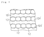
- a support member may be a structure 10' having plural grooves 10a' on which the cells and the like 12 are arranged as shown in Fig. 7.
- a support member may be a structure 10'' having plural dimples 10a'' on which the cells and the like 12 are arranged as shown in Fig. 8.
- a manual operation switch 30 connected to the interface unit 23 may be used. To be more precise, when an operator who observes the cells and the like 12 via the microscope 2 recognizes an objective optical property, the operator inputs a sensing signal to the microcomputer 20 by means of the switch 30.
- the sensing signal is stored as data corresponding to the objective optical property in the memory area corresponding to the coordinates of the recognized one of the cells and the like 12. Further, when any abnormal one of the cells and the like 12 is found via the microscope 2, it (12) may be picked up separately or may not be picked up by feeding a signal to the microcomputer 20 by means of the switch 30.
- the mesh 10 may be formed on a wafer using the semiconductor patterning technique. As an alternative to compressed air, another type of gas may be blown through the capillary 33. While in the above embodiment the liquid component of the solution 13 is drained by tilting the transparent container 3 as shown in Fig. 4, alternatively, the solution 13 may be drained by sucking it through the capillary 33.
Abstract
Description
- The present invention relates to a selecting device suitable for selecting cells and the like. Each of the cells and the like is, for example, cells clumped like a granule, microorganisms clumped like a granule and a gel bead which embraces cells or microorganisms by a carrier such as alginic acid, chitin or agar-agar.
- For example, in a process of forming a hybridoma which produces monoclonal antibodies, many droplets are formed from a culture medium such as alginic acid which embraces cells. The droplets are dropped into calcium chloride solution to form many gel beads. The cells are cultured in the gel beads, and then any of the gel beads which embrace cells producing monoclonal antibodies are selected from among all gel beads.
- Since the ratio of the gel beads which embrace cells producing monoclonal antibodies to all gel beads is as low as 1%, it is demanded to select the specific gel beads in an automatic, rapid and reliable manner.
- In case of getting microorganisms having specific property, since gel beads which embrace microorganisms are formed by the similar process as above, it is also demanded to select the specific gel beads from among all gel beads in the same way.
- In case cells or microorganisms are cultured in a normal culture medium unlike gel beads, they are usually clumped and formed into many granules. Thus, it is demanded to select the specific granular cells or granular microorganisms from among all granular cells or granular microorganisms in the same way.
- The objective cells and the like are identified by an optical property of cells themselves, an optical property of microorganisms themselves or an optical property of substance which was secreted from cells or microorganisms. For example, by adding a fluorescent agent combined with a substance which can combine with monoclonal antibodies to the culture medium, luminous granular cells producing monoclonal antibodies or gel beads which embrace luminous cells producing monoclonal antibodies can be identified under dark field of a microscope. Also, granular microorganisms having a specific color or gel beads of which color changes by multiplication of microorganisms embraced in them can be identified under light field of a microscope.
- After above identification step, the identified cells and the like are picked up by a needle piercing them or are sucked by a glass tube in a liquid.
- In the past, above selecting process is performed almost manually, and thus it is a time consuming and labor intensive operation.
- Besides, a gel bead is a minute sphere of which diameter usually ranges from about 0.1 mm to 5 mm, and cells clumped like a granule or microorganisms clumped like a granule has a shape of substantially sphere of which diameter is smaller than that of gel bead. Thus, in case of piercing the cells and the like by the needle, the cells and the like attempt to slip away from the needle. Namely the piercing operation is difficult. Even if the cells and the like are pierced, they soon fall off the needle.
- Besides, in case of sucking objective cells and the like by the glass tube, unnecessary cells and the like adjacent to the objective ones are sucked together.
- It is an object of the present invention to provide a selecting device for cells and the like, which can solve the above problems.
- The selecting device for the cells and the like according to the present invention comprises a support member capable of arranging the cells and the like thereon in a single layer, means for detecting each position of the cells and the like with respect to the support member, each position of the cells and the like with respect to the support member being determined by two dimensional coordinates, means for detecting each optical property of the cells and the like arranged on the support member, a memory device for storing data corresponding to the positions and the optical properties of the cells and the like, a pickup member capable of picking up each of the cells and the like arranged on the support member via an adhesive, a driving means for moving the pickup member relatively in the three dimensional directions with respect to the support member, a control device for controlling the driving device in accordance with the stored data so that the pickup member can pick up any of the cells and the like which has a specific optical property, and means for releasing each of the specific cells and the like which adheres to the pickup member from the pickup member.
- According to the present invention, by arranging the cells and the like in a single layer on the support member, each position of the cells and the like is fixed on a plane defined by the two dimensional coordinates. Namely, each position of the cells and the like with respect to the support member can be determined by the abscissa and ordinate. And each optical property of the cells and the like arranged on the support member can be correlated to each position of the cells and the like. The data corresponding to the positions and the optical properties of the cells and the like are stored in the memory device. In accordance with the stored data, the control device controls the driving means so that the pickup member moves relatively in the three dimensional directions with respect to the support member. Thereby the pickup member can pick up any of the cells and the like which has a specific optical property via the adhesive. Then, the pickup member is transferred above a container such as a micro well, and each of the specific cells and the like which adheres to the pickup member is released from the pickup member. Therefore, the selecting device according to the present invention can select the specific cells and the like in a rapid and reliable manner, and can contribute to automating of the selecting operation.
- Preferably, each of the cells and the like is cells clumped like a granule, microorganisms clumped like a granule or a gel bead embracing cells or microorganisms. Preferably, the support member is a mesh, a structure having plural grooves or a structure having plural dimples. Preferably, the pickup member is a capillary through which a current of gas is blown so that each of the specific cells and the like which adheres to the capillary is released from the capillary.
-
- Fig.1 is a view showing the construction of the selecting device of the embodiment according to the present invention;
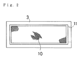
- Fig.2 is a plan view showing a transparent container of the embodiment according to the present invention;
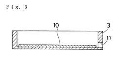
- Fig.3 is a cross-sectional view showing a transparent container of the embodiment according to the present invention;
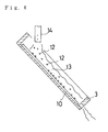
- Fig.4 illustrates the operation of the embodiment according to the present invention;
- Fig.5 illustrates the mesh of the embodiment according to the present invention;
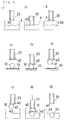
- Fig.6 illustrates the operation of the embodiment according to the present invention;
- Fig.7 illustrates a modified support member; and
- Fig.8 illustrates another modified support member.
- Referring to the drawings, the embodiments of the present invention are described.
- As shown in Fig.1, a selecting
device 1 is mounted on anoptical microscope 2. The selectingdevice 1 has afirst support frame 6 on which atransparent container 3 for containing cells and the like, acontainer 4 for containing adhesive and acontainer 5 including plural micro wells are mounted. Thefirst support frame 6 is movable on arail 8 fitted to asecond support frame 7. Therail 8 guides thefirst frame 6 into a substantially horizontal direction (X-axis direction) perpendicular to the page on which Fig.1 is drawn. Thesecond support frame 7 is movable on arail 9 fitted to themicroscope 2. Therail 9 guides thesecond frame 7 into a substantially horizontal direction (Y-axis direction) perpendicular to the X-axis direction. - As shown in Fig.2 and Fig.3, the top end of the
transparent container 3 is open. Amesh 10 is mounted on the inner bottom of thecontainer 3 as a support member. Adrain hole 11 is provided on the side wall of thecontainer 3. Asuspension 13 including cells and the like 12 is introduced into thecontainer 3 tilted from a horizontal plane as shown in Fig.4 through an inlet duct 14, then the liquid component of thesuspension 13 is drained through thedrain hole 11. Then the container is mounted on thefirst support frame 6. Thus the cells and the like 12 are arranged on themesh 10 along the X-axis and Y-axis. As shown in Fig.5, the size of each opening 10a of themesh 10 is set smaller than the size of each of the cells and the like 12 so that the cells and the like 12 are arranged in a single layer. As long as the cells and the like 12 are arranged, the size of each opening 10a may be slightly greater than the size of each of the cells and the like 12. In case each of the cells and the like 12 is a gel bead which embraces cells or microorganisms, each diameter of the gel beads usually ranges from about 0.1 mm to 5 mm. In case each of the cells and the like 12 is cells clumped like a granule or microorganisms clumped like a granule, each diameter of them is smaller than the diameter of a normal gel bead. Therefore the size of each opening 10a is determined depending on the diameters of the cells and the like 12. Preferably, the atmosphere surrounding thecontainer 3 is a humidified one in order to enhance the survival rate of cells and microorganisms. - Any of the cells and the like 12 have a specific optical property based on their own property or based on substance secreted from them. For example, by adding a fluorescent agent combined with a substance which can combine with monoclonal antibodies to a culture medium for the cells, granular cells producing monoclonal antibodies or gel beads which embrace cells producing monoclonal antibodies emit fluorescence under the dark field. In case granular cells or granular microorganisms have a specific color, by lighting the cells and the like 12, the reflective rate of the light of which wavelength agrees with the specific color increases. In case cells or microorganisms are achromatic, the lightness of the
gel beads 12 which embrace the cells or microorganisms changes by multiplication of cells or microorganisms under the light field. - To detect each optical property of the cells and the like 12, an
image pickup device 15 having an image sensor and a lens system is disposed below thecontainer 3. An automatic focusingdevice 16 which is used to focus the image of each of the cells and the like 12 on theimage pickup device 15 is provided. The automatic focusingdevice 16 is useful in case each diameter of the cells and the like 12 or the thickness of themesh 10 is not uniform. The automatic focusingdevice 16 has adistance sensor 16a measuring the distance to each of the cells and the like 12 and a movingdevice 16b moving the lens system. Thedistance sensor 16a and the movingdevice 16b are connected to a microcomputer (controller) 20 which is described later. Themicrocomputer 20 generates a signal according to the distance measured by thedistance sensor 16a, and the movingdevice 16b moves the lens system according to the signal from themicrocomputer 20 to focus the image of each of the cells and the like 12 on theimage pickup device 15. In case each of the cells and the like 12 has an optical property of fluorescence, image data corresponding to the intensity of the fluorescence are obtained by picking up the image of each of the cells and the like 12 under the dark field. In case each of the cells and the like 12 has a specific color or a specific lightness, image data corresponding to the color or the lightness are obtained by picking up the image of each of the cells and the like 12 under the light field. - Each optical property of the cells and the like 12 is stored in a
memory device 21 of themicrocomputer 20. To be more precise, themicrocomputer 20 comprises thememory device 21, acentral processor unit 22 and an input/output interface unit 23. Theimage pickup device 15 is connected to the input/output interface unit 23 via an analog-to-digital (A-D) converter which digitizes the image data corresponding to the optical properties of the cells and the like 12. Thememory device 21 has memory areas. Each position of the cells and the like 12 with respect to themesh 10 can be correlated to any of the memory areas. Each position of the cells and the like 12 with respect to themesh 10 is determined by the abscissa and ordinate. Each coordinates of the cells and the like 12 are detected bysensors microcomputer 20. Thereby the digitized image data of the cells and the like 12 are stored in the memory areas corresponding to the coordinates of the cells and the like 12. - A
support member 32 is fitted to themicroscope 2 via arail 31. Therail 31 guides thesupport member 32 into a substantially vertical direction (Z-axis direction) perpendicular to the X-axis and Y-axis directions. Thesupport member 32 supports a capillary (pickup member) 33 which is connected to a high-pressure air source 36 via anelectromagnetic valve 35. A drivingdevice 39 of theelectromagnetic valve 35 is connected to themicrocomputer 20. The capillary 33 is movable relatively along the X-axis, Y-axis and Z-axis with respect to themesh 10. Thus, the capillary 33 can contact a adhesive 40 inside thecontainer 4, and can pick up each of the cells and the like 12 arranged on themesh 10 via the adhesive 40, and can be located above any of micro wells inside thecontainer 5. As the adhesive 40 a viscous material which is physiologically less toxic, such as starch adhesive, is preferred. - Driving means are provided to move the capillary 33 relatively along the X-axis, Y-axis and Z-axis directions with respect to the
mesh 10. To be more precise, the driving means have adriving device 37 for moving thefirst support frame 6 in the X-axis direction with respect to therail 8, a drivingdevice 38 for moving thesecond support frame 7 in the Y-axis direction with respect to therail 9 and adriving device 34 for moving thesupport member 32 in the Z-axis direction with respect to therail 31. For example, each of the drivingdevices rails movable members devices rails movable members device microcomputer 20 so as to be controlled by themicrocomputer 20. - A
sensor 25 for measuring the travel of thefirst support frame 6 in the X-axis direction with respect to thefirst rail 8, asensor 26 for measuring the travel of thesecond support frame 7 in the Y-axis direction with respect to thesecond rail 9 and asensor 41 for measuring the travel of thesupport member 32 in the Z-axis direction with respect to therail 31 are provided. Each of thesensors devices sensors devices sensors microcomputer 20 so that each abscissa and each ordinate of the cells and the like 12 arranged on themesh 10 can be determined by the signals fed from thesensor sensor 41 is connected to the microcomputer so that the coordinate of the capillary 33 with respect to the cells and the like 12 along the Z-axis can be determined by the signal fed from thesensor 41. The origin of the X-axis, Y-axis and Z-axis may be set anywhere on themesh 10. - The selecting
device 1 constructed as above is controlled by themicrocomputer 20 as below according to the sequence of the control program stored in thememory device 21. - In the first place, one of the cells and the like 12 arranged on the
mesh 10 is picked up by theimage pickup device 15 to detect the optical property of it (12) via the automatic focusingdevice 16. The abscissa and the ordinate of it (12) are determined by the signals fed from thesensors memory device 21 and stored in the memory area corresponding to the coordinates of it (12). - In the next place, by the movements of the support frames 6, 7, another one of the cells and the like 12 is positioned on the focal point of the
image pickup device 15, and the same process as above is repeated. - By the repetition of above process, the optical data corresponding to the properties of all of the cells and the like 12 arranged on the
mesh 10 are stored in thememory device 21 together with the coordinate data corresponding to the coordinates of all of them (12). - In the next place, the support frames 6, 7 are moved so that the
adhesive container 4 is located below the capillary 33 as shown in Fig.6(1), and then, thesupport member 32 is moved so that the adhesive 40 sticks to the bottom end of the capillary 33 as shown in Fig.6(2), Fig.6(3). Then the support frames 6, 7 are moved so that the capillary 33 is located above one of the cells and the like 12 which has a specific optical property as shown in Fig.6(4). For example, in case the cells and the like 12 emit fluorescence, the capillary 33 is located above any of the cells and the like 12 of which intensity of the fluorescence is beyond a certain threshold level. Then thesupport member 32 is moved so that the capillary 32 picks up the one of the cells and the like 12 via the adhesive 40 as shown in Fig.6(5), Fig.6(6). Then the support frames 6, 7 are moved so that one of themicro wells 42 in thecontainer 5 is located under the capillary 33 as shown in Fig.6(7). Then a signal for opening thevalve 35 is fed to the drivingdevice 39 so that a current of compressed air is blown through the capillary 33 (illustrated by the arrow in Fig.6(8)). Thereby, the one of the cells and the like 12 which adheres to the capillary 33 is released, and it (12) is received by themicro well 42 as shown in Fig.6(9). Themicro well 42 contain abuffer solution 43. In case the pressure of the compressed air blown through the capillary 33 is not so high or in case each of the cell and the like 12 is gel bead of which hardness is high, thebuffer solution 43 is not necessary. By repeating the above process illustrated by Fig.6(1) ∼ (9), any of cells and the like 12 which have the objective optical property are respectively received by themicro wells 42. - By the above process, cells or microorganisms having a specific useful substance can be obtained.
- The present invention is not limited to the above embodiment. For example, while in the above embodiment the support member is a
mesh 10, alternatively, a support member may be a structure 10' havingplural grooves 10a' on which the cells and the like 12 are arranged as shown in Fig. 7. Alternatively, a support member may be a structure 10'' havingplural dimples 10a'' on which the cells and the like 12 are arranged as shown in Fig. 8. As an alternative to the use of theimage pickup device 15, a manual operation switch 30 connected to theinterface unit 23 may be used. To be more precise, when an operator who observes the cells and the like 12 via themicroscope 2 recognizes an objective optical property, the operator inputs a sensing signal to themicrocomputer 20 by means of the switch 30. The sensing signal is stored as data corresponding to the objective optical property in the memory area corresponding to the coordinates of the recognized one of the cells and the like 12. Further, when any abnormal one of the cells and the like 12 is found via themicroscope 2, it (12) may be picked up separately or may not be picked up by feeding a signal to themicrocomputer 20 by means of the switch 30. Themesh 10 may be formed on a wafer using the semiconductor patterning technique. As an alternative to compressed air, another type of gas may be blown through the capillary 33. While in the above embodiment the liquid component of thesolution 13 is drained by tilting thetransparent container 3 as shown in Fig. 4, alternatively, thesolution 13 may be drained by sucking it through the capillary 33.
Claims (8)
- A selecting device for cells and the like, comprising a support member (10, 10', 10'') capable of arranging the cells and the like (12) thereon in a single layer, means (25, 26) for detecting each position of the cells and the like (12) with respect to the support member (10, 10', 10''), each position of the cells and the like with respect to the support member (10, 10', 10'') being determined by two dimensional coordinates, means (15) for detecting each optical property of the cells and the like (12) arranged on the support member (10, 10', 10''), a memory device (21) for storing data corresponding to the positions and the optical properties of the cells and the like (12), a pickup member (33) capable of picking up each of the cells and the like (12) arranged on the support member (10, 10', 10'') via an adhesive (40), a driving means (34, 37, 38) for moving the pickup member (33) relatively in the three dimensional directions with respect to the support member (10, 10', 10''), a control device (20) for controlling the driving device (34, 37, 38) in accordance with said stored data so that the pickup member (33) can pick up any of the cells and the like (12) which has a specific optical property, and means for releasing each of the specific cells and the like (12) which adheres to the pickup member (33) from the pickup member (33).
- The selecting device according to claim 1, wherein each of the cells and the like (12) is cells clumped like a granule.
- The selecting device according to claim 1, wherein each of the cells and the like (12) is microorganisms clumped like a granule.
- The selecting device according to claim 1, wherein each of the cells and the like (12) is a gel bead.
- The selecting device according to claim 1, wherein the support member (10) is a mesh.
- The selecting device according to claim 1, wherein the support member (10') is a structure having plural grooves (10a').
- The selecting device according to claim 1, wherein the support member (10'') is a structure having plural dimples (10a'').
- The selecting device according to claim 1, wherein the pickup member (33) is a capillary through which a current of gas is blown.
Applications Claiming Priority (2)
| Application Number | Priority Date | Filing Date | Title |
|---|---|---|---|
| JP313955/91 | 1991-10-30 | ||
| JP3313955A JP3067347B2 (en) | 1991-10-30 | 1991-10-30 | Gel-like bead sorting equipment |
Publications (2)
| Publication Number | Publication Date |
|---|---|
| EP0539888A1 true EP0539888A1 (en) | 1993-05-05 |
| EP0539888B1 EP0539888B1 (en) | 1996-05-15 |
Family
ID=18047504
Family Applications (1)
| Application Number | Title | Priority Date | Filing Date |
|---|---|---|---|
| EP92118199A Expired - Lifetime EP0539888B1 (en) | 1991-10-30 | 1992-10-23 | Selecting device for cells and the like |
Country Status (4)
| Country | Link |
|---|---|
| US (1) | US5348883A (en) |
| EP (1) | EP0539888B1 (en) |
| JP (1) | JP3067347B2 (en) |
| DE (1) | DE69210753T2 (en) |
Cited By (25)
| Publication number | Priority date | Publication date | Assignee | Title |
|---|---|---|---|---|
| WO1995023960A1 (en) * | 1994-03-01 | 1995-09-08 | Government Of The United States, Represented By The Secretary Of The Department Of Health And Human Services | Isolation of cellular material under microscopic visualization |
| EP0819930A2 (en) * | 1996-07-19 | 1998-01-21 | Bayer Ag | Method and apparatus for screening molecules according to their individual binding affinity for at least one specified ligand |
| US5843657A (en) * | 1994-03-01 | 1998-12-01 | The United States Of America As Represented By The Department Of Health And Human Services | Isolation of cellular material under microscopic visualization |
| WO1999000658A1 (en) * | 1997-06-27 | 1999-01-07 | The Government Of The United States Of America, | Convex geometry adhesive film system for laser capture microdissection |
| WO1999045357A2 (en) * | 1998-03-02 | 1999-09-10 | Trustees Of Tufts College | Biosensor array comprising cell populations confined to microcavities |
| WO1999047922A2 (en) * | 1998-03-18 | 1999-09-23 | Massachusetts Institute Of Technology | Vascularized perfused microtissue/micro-organ arrays |
| WO2000058735A2 (en) * | 1999-03-31 | 2000-10-05 | Optigon Technologies | High throughput screening apparatus and methods for arraying microparticles |
| DE19815400C2 (en) * | 1998-04-06 | 2002-02-07 | Max Planck Gesellschaft | Device for taking samples from polymeric carrier materials |
| US6398932B1 (en) | 1997-06-24 | 2002-06-04 | Large Scale Proteomics Corp. | Automated system for two-dimensional electrophoresis |
| US6459994B1 (en) | 1998-05-29 | 2002-10-01 | Oxford Glycosciences (Uk) Ltd | Methods for computer-assisted isolation of proteins |
| US6480618B1 (en) | 1996-11-29 | 2002-11-12 | Oxford Glycosciences (Uk) Ltd. | Robotic device for removing selected portions of a polyacrylamide gel |
| US6554991B1 (en) | 1997-06-24 | 2003-04-29 | Large Scale Proteomics Corporation | Automated system for two-dimensional electrophoresis |
| WO2003036266A1 (en) * | 2001-10-24 | 2003-05-01 | P.A.L.M. Microlaser Technologies Ag | Laser microdissection system |
| US6743601B1 (en) | 1998-12-10 | 2004-06-01 | The United States Of America As Represented By The Department Of Health And Human Services | Non-contact laser capture microdissection |
| WO2004074424A2 (en) * | 2003-02-21 | 2004-09-02 | Fraunhofer-Gesellschaft zur Förderung der angewandten Forschung e.V. | Method and devices for transferring biological cells between a carrier and a probe |
| US6867038B2 (en) | 1994-03-01 | 2005-03-15 | The United States Of America As Represented By The Department Of Health And Human Services | Isolation of cellular material under microscopic visualization |
| WO2005073693A1 (en) * | 2004-02-02 | 2005-08-11 | Euroimmun Medizinische Labordiagnostika Ag | Method for producing solid-phase bonded bioreagents |
| NL1030102C2 (en) * | 2005-10-03 | 2007-04-04 | Ccm Beheer Bv | Fluorescence microscope. |
| WO2008037305A1 (en) * | 2006-09-25 | 2008-04-03 | Firma Dr.Roland Kilper | Apparatus and method for picking up, transporting and depositing microscopic samples |
| WO2009015837A1 (en) * | 2007-08-02 | 2009-02-05 | Fraunhofer-Gesellschaft zur Förderung der angewandten Forschung e.V. | Method and device for receiving biological cells from a stem cell culture |
| EP2083257A1 (en) * | 2008-01-25 | 2009-07-29 | Helmholtz Zentrum München Deutsches Forschungszentrum für Gesundheit und Umwelt GmbH | Method and device for transferring a microscopic, isolated sample, micro-dissection system with such a device and method for producing a nanovacuum device |
| US7887752B2 (en) | 2003-01-21 | 2011-02-15 | Illumina, Inc. | Chemical reaction monitor |
| US8318479B2 (en) | 2004-05-19 | 2012-11-27 | Massachusetts Institute Of Technology | Perfused three-dimensional cell/tissue disease models |
| US9638612B2 (en) | 2013-05-01 | 2017-05-02 | Roche Molecular Systems, Inc. | Selective release of sub-group of biological units |
| EP1686380B1 (en) * | 2005-01-27 | 2019-06-05 | Molecular Devices, LLC | Robotic apparatus for picking of cells with integrated spectroscopic capability and use thereof |
Families Citing this family (14)
| Publication number | Priority date | Publication date | Assignee | Title |
|---|---|---|---|---|
| JP2002515044A (en) * | 1996-08-21 | 2002-05-21 | スミスクライン・ビーチャム・コーポレイション | A rapid method for sequencing and synthesizing bead-based combinatorial libraries |
| US20020137890A1 (en) * | 1997-03-31 | 2002-09-26 | Genentech, Inc. | Secreted and transmembrane polypeptides and nucleic acids encoding the same |
| EP2360271A1 (en) | 1998-06-24 | 2011-08-24 | Illumina, Inc. | Decoding of array sensors with microspheres |
| AU6226799A (en) * | 1998-10-13 | 2000-05-01 | Yissum Research Development Company Of The Hebrew University Of Jerusalem | Hydrocolloid coating of cells |
| DE10015157A1 (en) | 2000-03-27 | 2001-10-18 | P A L M Gmbh | Collecting device for objects dissolved out of mass, especially by laser radiation, has control system automatically generating accommodation unit displacement signals |
| FR2820756B1 (en) * | 2001-02-09 | 2004-01-23 | Daniel Attias | INCUBATOR AND INCUBATION PROCESS ENDING THE ORGANIZATION SET TO INCUBATE |
| JP4485408B2 (en) * | 2005-05-20 | 2010-06-23 | 株式会社日立製作所 | Sampling sheet and method for producing the sampling sheet |
| DE102005026540A1 (en) * | 2005-06-08 | 2006-12-14 | P.A.L.M. Microlaser Technologies Ag | Method and device for handling objects |
| JP5010867B2 (en) * | 2005-09-22 | 2012-08-29 | オリンパス株式会社 | Culture microscope equipment |
| DE102005053669B4 (en) | 2005-11-08 | 2007-12-13 | Kilper, Roland, Dr. | Sample manipulation device |
| AT506233B1 (en) * | 2008-01-18 | 2009-07-15 | Leica Mikrosysteme Gmbh | MICROMANIPULATOR FOR A CRYOMICROTOM |
| JP5290690B2 (en) * | 2008-10-02 | 2013-09-18 | 古河電気工業株式会社 | Fine particle screening device |
| KR101363791B1 (en) * | 2012-03-30 | 2014-02-20 | 고려대학교 산학협력단 | Apparatus for measuring cell viability and method for analyzing cell viability |
| WO2019089536A1 (en) * | 2017-10-30 | 2019-05-09 | University Of Pittsburgh-Of The Commonwealth System Of Higher Education | Methods and systems comprising modified pipettes for transferring and preserving biomaterial |
Citations (8)
| Publication number | Priority date | Publication date | Assignee | Title |
|---|---|---|---|---|
| US3853711A (en) * | 1970-06-22 | 1974-12-10 | Biotec Ab | Installation for automation of microbiological work techniques |
| CA1020068A (en) * | 1975-06-10 | 1977-11-01 | Edward T. Sheaff | Device for examining biological specimens |
| DE2853956A1 (en) * | 1978-12-14 | 1980-06-19 | Volker Dr Thran | TRANSPORTABLE DEVICE FOR TAKING SAMPLES FOR MICROBIOLOGICAL, IN PARTICULAR BACTERIOLOGICAL EXAMINATIONS OF SURFACES |
| EP0094193A2 (en) * | 1982-05-10 | 1983-11-16 | Bar-Ilan University | System and methods for cell selection |
| EP0168238A2 (en) * | 1984-07-11 | 1986-01-15 | FMC Corporation | Colony replicating device |
| EP0347579A2 (en) * | 1988-06-01 | 1989-12-27 | Daimler-Benz Aerospace Aktiengesellschaft | Device having a specific support structure for receiving, analysing and treating samples |
| WO1991005253A1 (en) * | 1989-10-05 | 1991-04-18 | Engstroem Gunnar | Method and apparatus for studying the reaction pattern of cells/cell aggregates during perfusion by a test medium |
| US5073495A (en) * | 1988-10-21 | 1991-12-17 | Large Scale Biology Corporation | Apparatus for isolating cloned vectors and cells having a recovery device |
Family Cites Families (17)
| Publication number | Priority date | Publication date | Assignee | Title |
|---|---|---|---|---|
| DE240908C (en) * | ||||
| GB1584037A (en) * | 1977-12-12 | 1981-02-04 | Sheepbridge Eng Ltd | Centrifugal casting dies |
| DE2817503A1 (en) * | 1978-04-21 | 1979-10-31 | Merck Patent Gmbh | FOIL FOR CLAPPING MICROORGANISMS |
| SU1017725A1 (en) * | 1982-01-07 | 1983-05-15 | Ростовский Научно-Исследовательский Институт Медицинской Паразитологии | Sampler |
| US4613573A (en) * | 1982-05-20 | 1986-09-23 | Hitachi, Ltd. | Automatic bacterial colony transfer apparatus |
| US4629687A (en) * | 1982-07-29 | 1986-12-16 | Board Of Trustees Of Michigan State University | Positive selection sorting of cells |
| JPS5978680A (en) * | 1982-10-26 | 1984-05-07 | Ajinomoto Co Inc | Device for transferring microorganism |
| JPS611378A (en) * | 1984-06-14 | 1986-01-07 | Hitachi Electronics Eng Co Ltd | Automatic colony transplantater |
| JPS61115481A (en) * | 1984-11-09 | 1986-06-03 | Hitachi Electronics Eng Co Ltd | Method for controlling depth of transplantation needle in automatic colony transplantation apparatus |
| JPS61115482A (en) * | 1984-11-09 | 1986-06-03 | Hitachi Electronics Eng Co Ltd | Method for feeding transplantation needle in automatic colony transplantation apparatus |
| JPS6265700A (en) * | 1985-09-17 | 1987-03-24 | Datsuku Eng Kk | Transplantation of colony |
| AU7488787A (en) * | 1986-05-14 | 1987-12-01 | Life Technologies, Inc. | Plate screens |
| JP2590459B2 (en) * | 1986-08-21 | 1997-03-12 | 株式会社島津製作所 | Cell capture device |
| SU1537265A1 (en) * | 1987-06-18 | 1990-01-23 | Всесоюзный научно-исследовательский институт ветеринарной санитарии | Method of checking quality of disinfection |
| FR2628530B1 (en) * | 1988-03-08 | 1994-01-28 | Chemunex Sa | APPARATUS AND METHOD FOR DETECTION AND NUMERATION OF FLUORESCENT PARTICLES, CARRIED BY A SOLID SUPPORT |
| JPH02307164A (en) * | 1989-05-22 | 1990-12-20 | Hitachi Electron Eng Co Ltd | System and device for detection of microorganism colony |
| JPH03240482A (en) * | 1990-02-16 | 1991-10-25 | Hitachi Electron Eng Co Ltd | Method for transplanting colony to liquid culture medium |
-
1991
- 1991-10-30 JP JP3313955A patent/JP3067347B2/en not_active Expired - Fee Related
-
1992
- 1992-10-23 DE DE69210753T patent/DE69210753T2/en not_active Expired - Fee Related
- 1992-10-23 EP EP92118199A patent/EP0539888B1/en not_active Expired - Lifetime
- 1992-10-29 US US07/968,530 patent/US5348883A/en not_active Expired - Lifetime
Patent Citations (8)
| Publication number | Priority date | Publication date | Assignee | Title |
|---|---|---|---|---|
| US3853711A (en) * | 1970-06-22 | 1974-12-10 | Biotec Ab | Installation for automation of microbiological work techniques |
| CA1020068A (en) * | 1975-06-10 | 1977-11-01 | Edward T. Sheaff | Device for examining biological specimens |
| DE2853956A1 (en) * | 1978-12-14 | 1980-06-19 | Volker Dr Thran | TRANSPORTABLE DEVICE FOR TAKING SAMPLES FOR MICROBIOLOGICAL, IN PARTICULAR BACTERIOLOGICAL EXAMINATIONS OF SURFACES |
| EP0094193A2 (en) * | 1982-05-10 | 1983-11-16 | Bar-Ilan University | System and methods for cell selection |
| EP0168238A2 (en) * | 1984-07-11 | 1986-01-15 | FMC Corporation | Colony replicating device |
| EP0347579A2 (en) * | 1988-06-01 | 1989-12-27 | Daimler-Benz Aerospace Aktiengesellschaft | Device having a specific support structure for receiving, analysing and treating samples |
| US5073495A (en) * | 1988-10-21 | 1991-12-17 | Large Scale Biology Corporation | Apparatus for isolating cloned vectors and cells having a recovery device |
| WO1991005253A1 (en) * | 1989-10-05 | 1991-04-18 | Engstroem Gunnar | Method and apparatus for studying the reaction pattern of cells/cell aggregates during perfusion by a test medium |
Cited By (57)
| Publication number | Priority date | Publication date | Assignee | Title |
|---|---|---|---|---|
| US6204030B1 (en) | 1994-03-01 | 2001-03-20 | The United States Of America As Represented By The Secretary Of The Department Of Health And Human Services | Isolation of cellular material under microscopic visualization |
| US6569639B2 (en) | 1994-03-01 | 2003-05-27 | The United States Of America As Represented By The Department Of Health And Human Services | Isolation of cellular material under microscopic visualization |
| US6010888A (en) * | 1994-03-01 | 2000-01-04 | The United States Of America As Represented By The Department Of Health And Human Services | Isolation of cellular material under microscopic visualization |
| AU691263B2 (en) * | 1994-03-01 | 1998-05-14 | Government Of The United States Of America, As Represented By The Secretary Of The Department Of Health And Human Services, The | Isolation of cellular material under microscopic visualization |
| US5843644A (en) * | 1994-03-01 | 1998-12-01 | The United States Of America As Represented By The Secretary Of The Department Of Health And Human Services | Isolation of cellular material under microscopic visualization using an adhesive/extraction reagent tipped probe |
| US5843657A (en) * | 1994-03-01 | 1998-12-01 | The United States Of America As Represented By The Department Of Health And Human Services | Isolation of cellular material under microscopic visualization |
| WO1995023960A1 (en) * | 1994-03-01 | 1995-09-08 | Government Of The United States, Represented By The Secretary Of The Department Of Health And Human Services | Isolation of cellular material under microscopic visualization |
| US6867038B2 (en) | 1994-03-01 | 2005-03-15 | The United States Of America As Represented By The Department Of Health And Human Services | Isolation of cellular material under microscopic visualization |
| EP0819930A3 (en) * | 1996-07-19 | 1999-12-22 | Bayer Ag | Method and apparatus for screening molecules according to their individual binding affinity for at least one specified ligand |
| EP0819930A2 (en) * | 1996-07-19 | 1998-01-21 | Bayer Ag | Method and apparatus for screening molecules according to their individual binding affinity for at least one specified ligand |
| US6713264B2 (en) | 1996-07-19 | 2004-03-30 | Bayer Aktiengesellschaft | Process and device for the screening of molecules with regard to their individual binding behaviour towards at least one given ligand |
| DE19629141A1 (en) * | 1996-07-19 | 1998-04-16 | Bayer Ag | Method and device for screening molecules for their individual binding behavior to at least one predetermined ligand |
| US6480618B1 (en) | 1996-11-29 | 2002-11-12 | Oxford Glycosciences (Uk) Ltd. | Robotic device for removing selected portions of a polyacrylamide gel |
| US6554991B1 (en) | 1997-06-24 | 2003-04-29 | Large Scale Proteomics Corporation | Automated system for two-dimensional electrophoresis |
| US6416644B1 (en) | 1997-06-24 | 2002-07-09 | Large Scale Proteomics Corp. | Automated system for two-dimensional electrophoresis |
| US6482303B2 (en) | 1997-06-24 | 2002-11-19 | Large Scale Proteomics Corp. | Automated system for two-dimensional electrophoresis |
| US6398932B1 (en) | 1997-06-24 | 2002-06-04 | Large Scale Proteomics Corp. | Automated system for two-dimensional electrophoresis |
| AU744131B2 (en) * | 1997-06-27 | 2002-02-14 | Government Of The United States Of America, As Represented By The Secretary Of The Department Of Health And Human Services, The | Convex geometry adhesive film system for laser capture microdissection |
| WO1999000658A1 (en) * | 1997-06-27 | 1999-01-07 | The Government Of The United States Of America, | Convex geometry adhesive film system for laser capture microdissection |
| WO1999045357A3 (en) * | 1998-03-02 | 2000-04-27 | Tufts College | Biosensor array comprising cell populations confined to microcavities |
| WO1999045357A2 (en) * | 1998-03-02 | 1999-09-10 | Trustees Of Tufts College | Biosensor array comprising cell populations confined to microcavities |
| US6377721B1 (en) | 1998-03-02 | 2002-04-23 | Trustees Of Tufts College | Biosensor array comprising cell populations confined to microcavities |
| US6197575B1 (en) | 1998-03-18 | 2001-03-06 | Massachusetts Institute Of Technology | Vascularized perfused microtissue/micro-organ arrays |
| WO1999047922A3 (en) * | 1998-03-18 | 1999-11-04 | Massachusetts Inst Technology | Vascularized perfused microtissue/micro-organ arrays |
| WO1999047922A2 (en) * | 1998-03-18 | 1999-09-23 | Massachusetts Institute Of Technology | Vascularized perfused microtissue/micro-organ arrays |
| DE19815400C2 (en) * | 1998-04-06 | 2002-02-07 | Max Planck Gesellschaft | Device for taking samples from polymeric carrier materials |
| US6991714B1 (en) | 1998-04-06 | 2006-01-31 | Max-Planck-Gesellschaft Zur Foederung Der Wissenschaften E.V. | Apparatus and method for taking samples from polymer support material |
| US6459994B1 (en) | 1998-05-29 | 2002-10-01 | Oxford Glycosciences (Uk) Ltd | Methods for computer-assisted isolation of proteins |
| US6743601B1 (en) | 1998-12-10 | 2004-06-01 | The United States Of America As Represented By The Department Of Health And Human Services | Non-contact laser capture microdissection |
| WO2000058735A3 (en) * | 1999-03-31 | 2001-05-31 | Optigon Technologies | High throughput screening apparatus and methods for arraying microparticles |
| WO2000058735A2 (en) * | 1999-03-31 | 2000-10-05 | Optigon Technologies | High throughput screening apparatus and methods for arraying microparticles |
| WO2003036266A1 (en) * | 2001-10-24 | 2003-05-01 | P.A.L.M. Microlaser Technologies Ag | Laser microdissection system |
| DE10152404C5 (en) * | 2001-10-24 | 2017-06-08 | Carl Zeiss Microscopy Gmbh | Laser microdissection |
| US6930764B2 (en) | 2001-10-24 | 2005-08-16 | P.A.L.M. Microlaser Technologies Ag | Laser microdissection system |
| US8592214B2 (en) | 2003-01-21 | 2013-11-26 | Illumina, Inc. | Chemical reaction monitor |
| US7887752B2 (en) | 2003-01-21 | 2011-02-15 | Illumina, Inc. | Chemical reaction monitor |
| WO2004074426A2 (en) * | 2003-02-21 | 2004-09-02 | Fraunhofer-Gesellschaft zur Förderung der angewandten Forschung e.V. | Method and devices for non-traumatic movement of a probe through biological cell material |
| US8586341B2 (en) | 2003-02-21 | 2013-11-19 | Fraunhofer-Gesellschaft Zur Forderung Der Angewandten Forschung E.V. | Method and devices for non-traumatic movement of a probe through biological cell material |
| WO2004074424A2 (en) * | 2003-02-21 | 2004-09-02 | Fraunhofer-Gesellschaft zur Förderung der angewandten Forschung e.V. | Method and devices for transferring biological cells between a carrier and a probe |
| WO2004074426A3 (en) * | 2003-02-21 | 2004-12-16 | Fraunhofer Ges Forschung | Method and devices for non-traumatic movement of a probe through biological cell material |
| WO2004074424A3 (en) * | 2003-02-21 | 2005-01-27 | Fraunhofer Ges Forschung | Method and devices for transferring biological cells between a carrier and a probe |
| US7393629B2 (en) | 2003-02-21 | 2008-07-01 | Fraunhofer-Gesellschaft Zur Forderung Der Angewandten Forschung E.V. | Method and devices for transferring biological cells between a carrier and a probe |
| KR100892755B1 (en) * | 2003-02-21 | 2009-04-15 | 프라운호퍼-게젤샤프트 추르 푀르데룽 데어 안제반텐 포르슝 에 파우 | Method and devices for non-traumatic movement of a probe through biological cell material |
| WO2005073693A1 (en) * | 2004-02-02 | 2005-08-11 | Euroimmun Medizinische Labordiagnostika Ag | Method for producing solid-phase bonded bioreagents |
| US8318479B2 (en) | 2004-05-19 | 2012-11-27 | Massachusetts Institute Of Technology | Perfused three-dimensional cell/tissue disease models |
| EP1686380B1 (en) * | 2005-01-27 | 2019-06-05 | Molecular Devices, LLC | Robotic apparatus for picking of cells with integrated spectroscopic capability and use thereof |
| CN101292187B (en) * | 2005-10-03 | 2010-09-29 | C.C.M.控股有限公司 | Fluorescence microscope |
| US8000003B2 (en) | 2005-10-03 | 2011-08-16 | C.C.M. Beheer B.V. | Fluorescence microscope |
| WO2007040390A1 (en) * | 2005-10-03 | 2007-04-12 | C.C.M. Beheer B.V. | Fluorescence microscope |
| NL1030102C2 (en) * | 2005-10-03 | 2007-04-04 | Ccm Beheer Bv | Fluorescence microscope. |
| WO2008037305A1 (en) * | 2006-09-25 | 2008-04-03 | Firma Dr.Roland Kilper | Apparatus and method for picking up, transporting and depositing microscopic samples |
| US8268265B2 (en) | 2006-09-25 | 2012-09-18 | Roland Kilper | Apparatus and method for picking up, transporting, and depositing microscopic samples |
| WO2009015837A1 (en) * | 2007-08-02 | 2009-02-05 | Fraunhofer-Gesellschaft zur Förderung der angewandten Forschung e.V. | Method and device for receiving biological cells from a stem cell culture |
| US8573073B2 (en) | 2008-01-25 | 2013-11-05 | Helmholtz Zentrum Muenchen Deutsches Forschungszentrum Fur Gesundheit Und Umwelt Gmbh | Method and device for transferring a microscopic, isolated sample |
| WO2009092495A1 (en) * | 2008-01-25 | 2009-07-30 | Helmholtz Zentrum München Deutsches Forschungszentrum Für Gesundheit Und Umwelt Gmbh | Method and device for transferring a microscopic, insulated sample, micro-dissection system comprising such a device and method for the production of a nano-vacuum |
| EP2083257A1 (en) * | 2008-01-25 | 2009-07-29 | Helmholtz Zentrum München Deutsches Forschungszentrum für Gesundheit und Umwelt GmbH | Method and device for transferring a microscopic, isolated sample, micro-dissection system with such a device and method for producing a nanovacuum device |
| US9638612B2 (en) | 2013-05-01 | 2017-05-02 | Roche Molecular Systems, Inc. | Selective release of sub-group of biological units |
Also Published As
| Publication number | Publication date |
|---|---|
| EP0539888B1 (en) | 1996-05-15 |
| DE69210753D1 (en) | 1996-06-20 |
| JP3067347B2 (en) | 2000-07-17 |
| JPH05127099A (en) | 1993-05-25 |
| US5348883A (en) | 1994-09-20 |
| DE69210753T2 (en) | 1996-10-02 |
Similar Documents
| Publication | Publication Date | Title |
|---|---|---|
| EP0539888B1 (en) | Selecting device for cells and the like | |
| CN101842671B (en) | Optical sensor system on a device for the treatment of liquids | |
| CN107589123B (en) | Device for appearance detection of protective cover plate of intelligent equipment | |
| CN1772428A (en) | Laser processing machine and method | |
| JPH07301637A (en) | Testee conveyor device | |
| WO2009110462A1 (en) | Living cell judging method for cell observation, image processing program for cell observation, and image processing device | |
| CA2324262A1 (en) | Confocal microscopy imaging system | |
| CN103308497A (en) | Method and microplate reader for investigating biological cells or cell cultures | |
| CN107228861A (en) | The defect detecting device of liquid crystal panel | |
| WO2015174356A1 (en) | Culture observation apparatus | |
| US20020015997A1 (en) | Capillary array-based sample screening | |
| CN106559977A (en) | For the device in substrate upper mounting component | |
| CN106940319B (en) | Optical fiber image transmission element defect detection method and device | |
| CN102368056A (en) | Device and method for defect inspection of plate transparent body | |
| US20190039070A1 (en) | Cell accommodating chip and screening method using the cell accommodating chip | |
| CN112362004B (en) | Cassette detection device and method, and substrate processing production line | |
| CN102565082A (en) | Position alignment device, position alignment method, and computer readable recording medium having position alignment program recorded thereon | |
| US20190225927A1 (en) | Collection method for fine particles and collection system | |
| CN106053484A (en) | Testing apparatus and method for foreign matters on surface of liquid crystal glass | |
| US20200040295A1 (en) | Cell transfer apparatus | |
| JP2018063187A (en) | Container structure and imaging system using the same | |
| CN109433282B (en) | Step biochip and gene sequencing device for detecting same | |
| US6597522B2 (en) | Optical system | |
| JP6859861B2 (en) | Manipulation system and how to drive the manipulation system | |
| JPS6258659B2 (en) |
Legal Events
| Date | Code | Title | Description |
|---|---|---|---|
| PUAI | Public reference made under article 153(3) epc to a published international application that has entered the european phase |
Free format text: ORIGINAL CODE: 0009012 |
|
| AK | Designated contracting states |
Kind code of ref document: A1 Designated state(s): DE FR GB |
|
| 17P | Request for examination filed |
Effective date: 19930713 |
|
| 17Q | First examination report despatched |
Effective date: 19950616 |
|
| GRAH | Despatch of communication of intention to grant a patent |
Free format text: ORIGINAL CODE: EPIDOS IGRA |
|
| GRAA | (expected) grant |
Free format text: ORIGINAL CODE: 0009210 |
|
| AK | Designated contracting states |
Kind code of ref document: B1 Designated state(s): DE FR GB |
|
| ET | Fr: translation filed | ||
| REF | Corresponds to: |
Ref document number: 69210753 Country of ref document: DE Date of ref document: 19960620 |
|
| PLBE | No opposition filed within time limit |
Free format text: ORIGINAL CODE: 0009261 |
|
| STAA | Information on the status of an ep patent application or granted ep patent |
Free format text: STATUS: NO OPPOSITION FILED WITHIN TIME LIMIT |
|
| 26N | No opposition filed | ||
| REG | Reference to a national code |
Ref country code: GB Ref legal event code: 746 Effective date: 19970916 |
|
| REG | Reference to a national code |
Ref country code: FR Ref legal event code: D6 |
|
| REG | Reference to a national code |
Ref country code: GB Ref legal event code: IF02 |
|
| PGFP | Annual fee paid to national office [announced via postgrant information from national office to epo] |
Ref country code: FR Payment date: 20051010 Year of fee payment: 14 |
|
| PGFP | Annual fee paid to national office [announced via postgrant information from national office to epo] |
Ref country code: GB Payment date: 20051019 Year of fee payment: 14 |
|
| PGFP | Annual fee paid to national office [announced via postgrant information from national office to epo] |
Ref country code: DE Payment date: 20051020 Year of fee payment: 14 |
|
| PG25 | Lapsed in a contracting state [announced via postgrant information from national office to epo] |
Ref country code: DE Free format text: LAPSE BECAUSE OF NON-PAYMENT OF DUE FEES Effective date: 20070501 |
|
| GBPC | Gb: european patent ceased through non-payment of renewal fee |
Effective date: 20061023 |
|
| REG | Reference to a national code |
Ref country code: FR Ref legal event code: ST Effective date: 20070629 |
|
| PG25 | Lapsed in a contracting state [announced via postgrant information from national office to epo] |
Ref country code: GB Free format text: LAPSE BECAUSE OF NON-PAYMENT OF DUE FEES Effective date: 20061023 |
|
| PG25 | Lapsed in a contracting state [announced via postgrant information from national office to epo] |
Ref country code: FR Free format text: LAPSE BECAUSE OF NON-PAYMENT OF DUE FEES Effective date: 20061031 |