EP0541022B1 - Machine tool part loading and unloading method and device, particularly for machining printed circuit boards - Google Patents
Machine tool part loading and unloading method and device, particularly for machining printed circuit boards Download PDFInfo
- Publication number
- EP0541022B1 EP0541022B1 EP92118697A EP92118697A EP0541022B1 EP 0541022 B1 EP0541022 B1 EP 0541022B1 EP 92118697 A EP92118697 A EP 92118697A EP 92118697 A EP92118697 A EP 92118697A EP 0541022 B1 EP0541022 B1 EP 0541022B1
- Authority
- EP
- European Patent Office
- Prior art keywords
- fact
- pack
- pin
- stage
- bar
- Prior art date
- Legal status (The legal status is an assumption and is not a legal conclusion. Google has not performed a legal analysis and makes no representation as to the accuracy of the status listed.)
- Expired - Lifetime
Links
Images


Classifications
-
- H—ELECTRICITY
- H05—ELECTRIC TECHNIQUES NOT OTHERWISE PROVIDED FOR
- H05K—PRINTED CIRCUITS; CASINGS OR CONSTRUCTIONAL DETAILS OF ELECTRIC APPARATUS; MANUFACTURE OF ASSEMBLAGES OF ELECTRICAL COMPONENTS
- H05K13/00—Apparatus or processes specially adapted for manufacturing or adjusting assemblages of electric components
- H05K13/0061—Tools for holding the circuit boards during processing; handling transport of printed circuit boards
-
- B—PERFORMING OPERATIONS; TRANSPORTING
- B23—MACHINE TOOLS; METAL-WORKING NOT OTHERWISE PROVIDED FOR
- B23Q—DETAILS, COMPONENTS, OR ACCESSORIES FOR MACHINE TOOLS, e.g. ARRANGEMENTS FOR COPYING OR CONTROLLING; MACHINE TOOLS IN GENERAL CHARACTERISED BY THE CONSTRUCTION OF PARTICULAR DETAILS OR COMPONENTS; COMBINATIONS OR ASSOCIATIONS OF METAL-WORKING MACHINES, NOT DIRECTED TO A PARTICULAR RESULT
- B23Q5/00—Driving or feeding mechanisms; Control arrangements therefor
-
- B—PERFORMING OPERATIONS; TRANSPORTING
- B23—MACHINE TOOLS; METAL-WORKING NOT OTHERWISE PROVIDED FOR
- B23Q—DETAILS, COMPONENTS, OR ACCESSORIES FOR MACHINE TOOLS, e.g. ARRANGEMENTS FOR COPYING OR CONTROLLING; MACHINE TOOLS IN GENERAL CHARACTERISED BY THE CONSTRUCTION OF PARTICULAR DETAILS OR COMPONENTS; COMBINATIONS OR ASSOCIATIONS OF METAL-WORKING MACHINES, NOT DIRECTED TO A PARTICULAR RESULT
- B23Q7/00—Arrangements for handling work specially combined with or arranged in, or specially adapted for use in connection with, machine tools, e.g. for conveying, loading, positioning, discharging, sorting
-
- H—ELECTRICITY
- H05—ELECTRIC TECHNIQUES NOT OTHERWISE PROVIDED FOR
- H05K—PRINTED CIRCUITS; CASINGS OR CONSTRUCTIONAL DETAILS OF ELECTRIC APPARATUS; MANUFACTURE OF ASSEMBLAGES OF ELECTRICAL COMPONENTS
- H05K3/00—Apparatus or processes for manufacturing printed circuits
- H05K3/0011—Working of insulating substrates or insulating layers
- H05K3/0044—Mechanical working of the substrate, e.g. drilling or punching
-
- Y—GENERAL TAGGING OF NEW TECHNOLOGICAL DEVELOPMENTS; GENERAL TAGGING OF CROSS-SECTIONAL TECHNOLOGIES SPANNING OVER SEVERAL SECTIONS OF THE IPC; TECHNICAL SUBJECTS COVERED BY FORMER USPC CROSS-REFERENCE ART COLLECTIONS [XRACs] AND DIGESTS
- Y10—TECHNICAL SUBJECTS COVERED BY FORMER USPC
- Y10T—TECHNICAL SUBJECTS COVERED BY FORMER US CLASSIFICATION
- Y10T408/00—Cutting by use of rotating axially moving tool
- Y10T408/03—Processes
-
- Y—GENERAL TAGGING OF NEW TECHNOLOGICAL DEVELOPMENTS; GENERAL TAGGING OF CROSS-SECTIONAL TECHNOLOGIES SPANNING OVER SEVERAL SECTIONS OF THE IPC; TECHNICAL SUBJECTS COVERED BY FORMER USPC CROSS-REFERENCE ART COLLECTIONS [XRACs] AND DIGESTS
- Y10—TECHNICAL SUBJECTS COVERED BY FORMER USPC
- Y10T—TECHNICAL SUBJECTS COVERED BY FORMER US CLASSIFICATION
- Y10T408/00—Cutting by use of rotating axially moving tool
- Y10T408/52—Cutting by use of rotating axially moving tool with work advancing or guiding means
Definitions
- the present invention relates to a method and relative device for loading and unloading parts on a machine tool, particularly for machining printed circuit boards.
- Machine tools and machining centers are frequently equipped with automatic part loading and unloading devices. Such devices, however, are unsuitable for loading and unloading printed circuit boards, which require extremely careful handling, and, indeed, prior to machining, are normally packed in groups of a given number of boards held together and protected by two auxiliary plates.
- One known device for loading and unloading packs of printed circuit boards provides for transferring the pack between a pack store and the work table of a drilling machine, and comprises a pack handling system the operating axes of which are necessarily controlled by a numerical control unit.
- a pack handling system the operating axes of which are necessarily controlled by a numerical control unit.
- it is also extremely cumbersome, by virtue of the space required both to the side of the drilling machine and for changing the pack store.
- a machine tool part loading and unloading device wherein a work table travels along at least one axis, and which comprises means for supporting the part, and means for transferring the part between said supporting means and a work position on the table; characterized by the fact that said transfer means comprise a device on said table for engaging the part; and said transfer being effected by moving said table along said axis.
- a method of loading and unloading parts between a support and the work table of a machine tool characterized by the fact that, for loading the part, it comprises a stage wherein a first element on said part is engaged by said table; a stage wherein said part is extracted from said support by moving said table; a stage wherein the extracted part is moved in relation to the table into an intermediate position; and a stage wherein said table is returned for re-engaging said element.
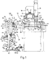
- Number 11 in Fig.1 indicates the bed of a printed circuit board drilling machine, which bed comprises a longitudinal slideway 13 of granite along which travels a work table 14.
- a screw 15 on slideway 13 engages a nut screw 16 integral with table 14, and is rotated by a numerical control servomotor (not shown) for moving table 14 along axis Y.
- the drilling machine also comprises a fixed crosspiece 17 also made of granite and along which travels transversely a carriage 18 supporting a drilling head 19 and which is moved along axis X in numerically controlled manner by means of a second screw-nut screw pair 21, 22.
- the side of the machine parallel to axis X and adjacent to drilling head 19 presents the operator controls and is hereinafter referred to as the front side, the opposite side hereinafter being referred to as the rear side.
- Drilling head 19 operates in known manner on a pack 23 of a number of printed circuit boards 24, e.g. three in Fig.2, to be drilled simultaneously, and which are packed between an auxiliary bottom plate 26 and an auxiliary cover plate 27. As shown by the dotted line in Fig.4, pack 23 is positioned on table 14 with the two longitudinal edges 28 parallel to axis Y, and the respective front and rear edges 29 and 31 perpendicular to axis Y.
- Bottom plate 26 presents a pair of pins 32, 33 (Fig.3) projecting perpendicularly beneath plate 26 and which act as locating pins for packing boards 24.
- Pins 32 and 33 are located at the mid point of respective sides 29 and 31, and are hereinafter referred to as front pin 32 and rear pin 33.
- the loading and unloading device comprises a removable store and a selecting or lifting device 37 by which the store is engaged.
- the store substantially consists of a rack 36 comprising four pillars 38 (Fig.3) mounted on respective castors 41 and connected in pairs by two side members 39.
- the pairs of pillars 38 are also connected by cross members 42, and the side members 39 on each side present an intermediate vertical bar 43.
- Rack 36 is divided vertically into two parts by an intermediate frame 44 (Fig.4) connected to pillars 38 and bars 43.
- the portion of rack 36 above frame 44 presents a number of superimposed cells 46 for housing respective packs 23 of boards for drilling. More specifically, each cell 46 is defined by a supporting surface consisting of two plates 47 arranged side by side so as to define on the supporting surface a central longitudinal passage 48 for housing and enabling the passage of pins 32 and 33 of pack 23.
- Each plate 47 is fitted in known manner to bar 43, and rests on a pair of brackets (not shown) fitted to the two pillars 38 on the corresponding side of rack 36.
- the brackets on each pillar 38 may consist of a single plate with arms corresponding with the location of plates 47.
- Lifter 37 comprises a fixed horizontal frame 52 floor mounted on height-adjustable feet; and two front connecting plates 53 fitted in removable manner, by means of a spherical articulated joint, to two brackets 54 on bed 11 of the drilling machine.
- Lifter 37 also comprises a movable horizontal frame 55, the longitudinal sides of which are connected to the corresponding sides of fixed frame 52 by a pair of pantographs 56.
- each pantograph 56 pivots on two pins 57 fitted respectively to the rear of frames 52 and 55, and presents two rollers 58 rolling inside two horizontal C-shaped guides 59 on the front of frames 52 and 55.
- the two pantographs 56 provide for moving frame 55 parallel to itself and in relation to fixed frame 52, and each of frames 52 and 55 is fitted with a respective cross member 60 on which pivots one end of a linear lift actuator 61, e.g. of the type comprising a reversible electric geared motor for driving a screw-nut screw pair.
- Movable frame 55 is fitted on top with a surface 62 in turn fitted with a prismatic guide 63 extending longitudinally along the center line of surface 62 and terminating at the rear with a wedge-shaped portion 64 projecting from frame 55.
- Guide 63 is engaged by two pairs of vertical-axis rollers 65 on two longitudinal brackets 66 fitted beneath the front side of intermediate frame 44 of rack 36.
- Frame 44 also presents four locating elements 67 engaged by four counterelements 68 on frame 52.
- One of front pillars 38 of rack 36 is fitted with a toothed bar 69 (Fig.1), the teeth of which present the same spacing as the vertical spacing between pairs of plates 47, and are detected by a proximity sensor 70 fitted to a column 71 (Fig.4) in turn fitted to frame 52 of lifter 37.
- Sensor 70 provides for supplying read signals to the electronic control unit of actuator 61 (Fig.3).
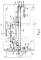
- rack 36 When detached from lifter 37, as shown in Fig.s 3 and 4, rack 36 may be transferred to a loading station where the machined packs 23 are removed and the rack loaded with further packs 23 for drilling. The loaded rack 36 is then positioned behind lifter 37 (to the left in Fig.s 3 and 4); and actuator 61 is operated so as to lower surface 62 so that guide 63 is on a level with rollers 65.
- Rack 36 is then pushed manually on to lifter 37, by engaging wedge 64 and guide 63 between rollers 65, and into the longitudinal position shown in Fig.1; and actuator 61 is operated so as to raise movable frame 55, engage counterelements 68 (Fig.4) and locating elements 67, and so raise rack 36.
- loading and unloading device 34 comprises a pack handling device substantially incorporated in a fixture 72 (Fig.1) on work table 14 of the machine.
- Fixture 72 provides for loading, positioning and unloading packs 23, and comprises a supporting plate 73 fitted to frame 74 of table 14 and having a device at the rear for engaging pins 32 and 33 of pack 23.
- Said device comprises a pair of jaws 75 (Fig.5) pivoting on two vertical pins 76 projecting beneath plate 73.
- each jaw comprises a front L-shaped arm 77 (Fig.6) connected by a connecting rod 78 to a respective rod 79 of a common pneumatic actuator 80 fitted to two tabs of a plate 81 fitted inside a bottom recess 82 (Fig.7) on plate 73.
- Each jaw 75 also comprises a Z-shaped bend 83 with a rectangular recess 84 for engaging pin 32, and a guide blade 85.
- plate 81 and connecting rods 78 may be eliminated by pivoting the ends of a single rod 79 and actuator 80 directly on the two arms 77.
- the pack handling device also comprises a device 86 for temporarily clamping pack 23, and which is fitted to a shaped transverse plate 87 (Fig.7) in turn fitted to a rear appendix 88 on fixed slideway 13.
- Device 86 comprises a retaining member consisting of a central prismatic bar 89 movable vertically and which, when raised, is located between the two bends 83 (Fig.6) of jaws 75.
- bar 89 presents two opposed vertical V-shaped grooves 90 and 91 for respectively locking rear pin 33 and front pin 32.
- Bar 89 is integral with a crosspiece 92 (Fig.8) fitted with two pins 93 guided inside two fixed sleeves 94, and which in turn is fitted to a rod 95 operated vertically by a pneumatic actuator 96 on plate 87.
- plate 87 On either side of bar 89, plate 87 is fitted with a further two pneumatic actuators 97 for vertically operating respective rods 98, the top end of each of which presents a lifting member consisting of a roller 99 (Fig.7) designed to engage bottom plate 26 (Fig.2) of pack 23.
- Plate 87 also presents two plates 100, each having an upper tab 101 cooperating with bottom plate 26 of pack 23; a photodiode 102; and a respective photoelectric sensor 103 for detecting the passage of rear edge 31 of pack 23.
- Plate 73 of fixture 72 presents a pair of openings 104 (Fig.4), next to recess 82, for enabling the passage of respective rollers 99 when plate 73 is backed up as shown in Fig.5; two upper recesses 105 for housing respective tabs 101 of plates 100 in the Fig.5 position; and an opening 106 (Fig.6) for enabling the passage of bar 89.
- Plate 73 also presents a device 107 (Fig.5) for accurately positioning pack 23, and which comprises a bar 108 for longitudinally guiding pins 32, 33, and fitted inside a long depression 109 formed on the top of plate 73.
- a locating bar 110 Next to the rear portion of bar 108, there is provided a locating bar 110 having a certain amount of transverse movement and two slots 111 engaging respective rollers 112 on plate 73.
- Device 107 also comprises a pneumatic actuator 113 housed in a depression 114 on the bottom of plate 73, and which, via rod 115, provides for operating one arm of a T-shaped lever 116 pivoting on pin 117 of plate 73.
- Bar 110 is operated by lever 116 via two connecting rods 118, two symmetrical cranks 119 pivoting on two pins 120 of plate 73, and two ties 140.
- top depression 109 is fitted inside with a further fixed bar 121 defining, with the front portion of bar 108, a fixed straight guide for pin 32.
- the rear end of bar 121 presents an inclined lead-in edge 122 for pin 32; and the front end of depression 109 presents a locator 123 having a V-shaped seat and defining a limit stop for pin 32.
- a bottom opening 124 in bars 121 and 122 houses arm 125 of a lever 126 in turn housed inside a further bottom depression 141 in plate 73 and pivoting on pin 127 of plate 73.
- Lever 126 is connected to rod 128 of a further pneumatic actuator 129; and arm 125 acts on pin 32 of pack 23, so as to push it positively on to locator 123.
- Carriage 18 on machining head 19 presents a number of retaining elements for front and rear edges 29 and 31 (Fig.4) of pack 23. More specifically, carriage 18 (Fig.1) presents a rear support 130 fitted with a first pneumatic actuator 131 located in the longitudinal plane of the axis of head 19, and which provides for vertically operating a blade 132 engaging rear edge 31 of pack 23.
- carriage 18 also presents a further support 133 located to the side of head 19 and having two brackets 134 and 135.
- Bracket 134 is fitted with a further two pneumatic actuators 136 and 137 for vertically operating respective blades 138 and 139 guided inside bracket 135, located a given longitudinal distance apart, and which provide for individually engaging front edge 29 of pack 23.
- table 14 is backed up so that recesses 84 of jaws 75 (Fig.6) correspond with front pin 32 of pack 23, as shown in Fig.9A; tabs 101 of plates 110 (Fig.7) engage recesses 105 in plate 73; and actuator 80 (Fig.6) is operated so as to rotate arms 77 symmetrically via connecting rods 78 and so engage pin 32 inside recesses 84 on jaws 75.
- Table 14 is then moved forward, taking pin 32 with it inside jaws 75 and so withdrawing pack 23 from cell 46. As rear edge 31 of pack 23 abandons surface 47, the rear of pack 23 rests on the two tabs 101 of plates 100 (Fig.7); and table 14 is arrested upon rear edge 31 being detected by photoelectric sensor 103. Pin 33 at this point is located slightly forward in relation to bar 89, as shown in Fig.9B, and the control unit memorizes the length of pack 23 determined by sensor 103.
- actuator 96 (Fig.7) is operated so as to position the top portion of bar 89 behind pin 33 of pack 23; actuator 80 (Fig.6) opens jaws 75 to release pin 32; and table 14 is backed up again so as to first arrest pack 23 with rear pin 33 contacting groove 90 of bar 89.
- table 14 causes pack 23 to slide on to plate 73, and pin 32 to engage and slide inside the gap between bars 108 and 110 (Fig.5), which movement is arrested according to the length of pack 23 detected by sensor 103, so that table 14 is finally positioned as shown in Fig.9C wherein jaws 75 correspond with rear pin 33 of pack 23.
- Actuator 113 is then operated so as to rotate lever 116 anticlockwise, together with cranks 119; via connecting rods 118, cranks 119 move bar 110 into the Fig.5 position wherein it closes against bar 108 so that pin 33 is engaged by bars 108 and 110; table 14 is again moved forward, together with pack 23, until edge 31 of pack 23 moves slightly past blade 132 (Fig.1); bar 110 is opened by actuator 113; bar 89 is lowered by actuator 96 (Fig.1); carriage 18 is positioned transversely so that blade 132 corresponds with the mid point of edge 31 of pack 23; and actuator 131 is operated so as to position blade 132 behind edge 31 of pack 23, as shown in Fig.9D.
- Table 14 is then backed up once more so that pack 23, held by blades 132, slides forward over plate 73 with both pins 32 and 33 between bars 108 and 110 (Fig.5); front pin 32 engages and is thus centered by the inclined edge 122 of front bar 121; and table 14 is arrested upon front pin 32 of pack 23 approaching fixed stop 123, as shown in Fig.9E.
- Actuator 129 is then operated so as to rotate lever 126 clockwise into the Fig.5 position; arm 125 engages pin 32 so as to bring it positively into contact with stop 123; and actuator 113 is operated so as to close bar 110 and so also center rear pin 33 and position pack 23 accurately in the work position.
- pack 23 When machined, pack 23 is unloaded off table 14 and returned to the pair of plates 47 from which it was removed.
- table 14 is first backed up, together with pack 23, so as to position front edge 29 of the pack behind front blade 138 of head 19; actuator 129 (Fig.5) is operated to free pin 32 from arm 125; actuator 113 moves bar 110 away from bar 108 so as to free pin 33; carriage 18 (Fig.1) is moved transversely so as to position blades 138 and 139 on the center line of pack 23; and actuator 136 is operated so as to lower blade 138, as shown in Fig.10F.
- Table 14 is then moved forward by slightly more than the distance between blades 138 and 139, so that pack 23, held by blade 138, slides in relation to table 14 into the position shown in Fig.10G; blade 138 is raised; table 14 is backed up to position edge 29 behind rear blade 139 of head 19; and actuator 137 is operated to lower blade 139, as shown in Fig.10H.
- Table 14 is then moved forward, so that pack 23, held by blade 139, slides in relation to table 14; on reaching the end of its forward travel, as shown in Fig.10I, table 14 is reversed so as to move pack 23 backwards and detach it from blade 139, which is then restored to the raised idle position; at the same time, both actuators 97 (Fig.8) are operated so as to raise both rollers 99 slightly higher than the surface of plates 47, as shown by the dotted line in Fig.7.
- Table 14 is then moved forward together with pack 23, the pin 33 of which engages and is arrested by groove 91 (Fig.6) on bar 89. As table 14 continues moving, pack 23 slides over plate 73; and table 14 is arrested with jaws 75 corresponding with front pin 32, as shown in Fig.10M.
- jaws 75 are closed; bar 89 is lowered; table 14 is backed up into the position shown in Fig.10N wherein the whole of pack 23 is loaded on to plates 47; rollers 99 (Fig.7) are lowered into the idle position; jaws 75 are opened; table 14 is moved forward to release jaws 75 from rack 36; and lifter 37 (Fig.1) is operated to position the next cell 46 on rack 36 on a level with plate 73.
- the loading and unloading device provides for eliminating the additional device for transferring the packs between the store and work table, and consequently also the respective numerical control axis.
- it provides for accurately positioning the pack on the work table.
- the location of the lifter behind the drilling machine provides for troublefree access to the machine by the operator, thus enabling in-line installation of a number of similar machines, optimum utilization of the space around the machine, and the formation of a modular drilling center.
Description
- The present invention relates to a method and relative device for loading and unloading parts on a machine tool, particularly for machining printed circuit boards.
- Machine tools and machining centers are frequently equipped with automatic part loading and unloading devices. Such devices, however, are unsuitable for loading and unloading printed circuit boards, which require extremely careful handling, and, indeed, prior to machining, are normally packed in groups of a given number of boards held together and protected by two auxiliary plates.
- One known device for loading and unloading packs of printed circuit boards provides for transferring the pack between a pack store and the work table of a drilling machine, and comprises a pack handling system the operating axes of which are necessarily controlled by a numerical control unit. In addition to the complex design and high cost of the above known device, it is also extremely cumbersome, by virtue of the space required both to the side of the drilling machine and for changing the pack store.
- It is an object of the present invention to provide a highly straightforward, reliable part loading and unloading device designed to overcome the aforementioned drawbacks typically associated with known devices.
- According to the present invention, there is provided a machine tool part loading and unloading device wherein a work table travels along at least one axis, and which comprises means for supporting the part, and means for transferring the part between said supporting means and a work position on the table; characterized by the fact that said transfer means comprise a device on said table for engaging the part; and said transfer being effected by moving said table along said axis.
- According to the present invention, there is also provided a method of loading and unloading parts between a support and the work table of a machine tool, characterized by the fact that, for loading the part, it comprises a stage wherein a first element on said part is engaged by said table; a stage wherein said part is extracted from said support by moving said table; a stage wherein the extracted part is moved in relation to the table into an intermediate position; and a stage wherein said table is returned for re-engaging said element.
- A preferred non-limiting embodiment of the device according to the present invention will be described by way of example with reference to the accompanying drawings, in which:
- Fig.1 shows a partial side view of a printed circuit board drilling machine incorporating a loading and unloading device in accordance with the present invention;
- Fig.2 shows a partial larger-scale view of a pack of printed circuit boards for drilling;
- Fig.3 shows a partially sectioned side view of part of the Fig.1 device in a different operating position;
- Fig.4 shows a partially sectioned plan view of the Fig.3 device;
- Fig.5 shows a partially sectioned plan view of a fixture on the work table of the drilling machine;
- Fig.6 shows a partial larger-scale plan view of a detail in Fig.5;
- Fig.7 shows a larger-scale half section of a further detail in Fig.1;
- Fig.8 shows a section along line VIII-VIII in Fig.1;
- Fig.9 shows the operating sequence for loading a pack of printed circuit boards on to the table;
- Fig.10 shows the operating sequence for unloading the pack off the table.
-
Number 11 in Fig.1 indicates the bed of a printed circuit board drilling machine, which bed comprises alongitudinal slideway 13 of granite along which travels a work table 14. Ascrew 15 onslideway 13 engages anut screw 16 integral with table 14, and is rotated by a numerical control servomotor (not shown) for moving table 14 along axis Y. - The drilling machine also comprises a fixed
crosspiece 17 also made of granite and along which travels transversely acarriage 18 supporting adrilling head 19 and which is moved along axis X in numerically controlled manner by means of a second screw-nut screw pair drilling head 19 presents the operator controls and is hereinafter referred to as the front side, the opposite side hereinafter being referred to as the rear side. -
Drilling head 19 operates in known manner on apack 23 of a number of printedcircuit boards 24, e.g. three in Fig.2, to be drilled simultaneously, and which are packed between anauxiliary bottom plate 26 and anauxiliary cover plate 27. As shown by the dotted line in Fig.4,pack 23 is positioned on table 14 with the two longitudinal edges 28 parallel to axis Y, and the respective front andrear edges -
Bottom plate 26 presents a pair ofpins 32, 33 (Fig.3) projecting perpendicularly beneathplate 26 and which act as locating pins forpacking boards 24.Pins respective sides front pin 32 andrear pin 33. - The loading and unloading device, indicated as a whole by 34, comprises a removable store and a selecting or
lifting device 37 by which the store is engaged. The store substantially consists of arack 36 comprising four pillars 38 (Fig.3) mounted onrespective castors 41 and connected in pairs by twoside members 39. The pairs ofpillars 38 are also connected bycross members 42, and theside members 39 on each side present an intermediatevertical bar 43. -
Rack 36 is divided vertically into two parts by an intermediate frame 44 (Fig.4) connected topillars 38 andbars 43. The portion ofrack 36 aboveframe 44 presents a number ofsuperimposed cells 46 for housingrespective packs 23 of boards for drilling. More specifically, eachcell 46 is defined by a supporting surface consisting of twoplates 47 arranged side by side so as to define on the supporting surface a centrallongitudinal passage 48 for housing and enabling the passage ofpins pack 23. - Each
plate 47 is fitted in known manner to bar 43, and rests on a pair of brackets (not shown) fitted to the twopillars 38 on the corresponding side ofrack 36. The brackets on eachpillar 38 may consist of a single plate with arms corresponding with the location ofplates 47. - Between the two
top cross members 42, there are fitted two longitudinalprismatic bars 49 on which travels aslide 50 fitted with a vertical bar or blade 51 for rearwardly arrestingpacks 23 and which is housed insidepassages 48 between pairs ofplates 47.Slide 50 is positioned longitudinally onbars 49 according to the length ofpack 23 for drilling, and is secured by setscrews. -
Lifter 37 comprises a fixedhorizontal frame 52 floor mounted on height-adjustable feet; and two front connectingplates 53 fitted in removable manner, by means of a spherical articulated joint, to twobrackets 54 onbed 11 of the drilling machine.Lifter 37 also comprises a movablehorizontal frame 55, the longitudinal sides of which are connected to the corresponding sides offixed frame 52 by a pair ofpantographs 56. - More specifically, each
pantograph 56 pivots on twopins 57 fitted respectively to the rear offrames rollers 58 rolling inside two horizontal C-shaped guides 59 on the front offrames pantographs 56 provide for movingframe 55 parallel to itself and in relation to fixedframe 52, and each offrames respective cross member 60 on which pivots one end of alinear lift actuator 61, e.g. of the type comprising a reversible electric geared motor for driving a screw-nut screw pair. -
Movable frame 55 is fitted on top with asurface 62 in turn fitted with aprismatic guide 63 extending longitudinally along the center line ofsurface 62 and terminating at the rear with a wedge-shaped portion 64 projecting fromframe 55.Guide 63 is engaged by two pairs of vertical-axis rollers 65 on twolongitudinal brackets 66 fitted beneath the front side ofintermediate frame 44 ofrack 36. -
Frame 44 also presents four locating elements 67 engaged by four counterelements 68 onframe 52. One offront pillars 38 ofrack 36 is fitted with a toothed bar 69 (Fig.1), the teeth of which present the same spacing as the vertical spacing between pairs ofplates 47, and are detected by aproximity sensor 70 fitted to a column 71 (Fig.4) in turn fitted toframe 52 oflifter 37.Sensor 70 provides for supplying read signals to the electronic control unit of actuator 61 (Fig.3). - When detached from
lifter 37, as shown in Fig.s 3 and 4,rack 36 may be transferred to a loading station where themachined packs 23 are removed and the rack loaded withfurther packs 23 for drilling. The loadedrack 36 is then positioned behind lifter 37 (to the left in Fig.s 3 and 4); andactuator 61 is operated so as tolower surface 62 so thatguide 63 is on a level withrollers 65. - Rack 36 is then pushed manually on to lifter 37, by engaging wedge 64 and
guide 63 betweenrollers 65, and into the longitudinal position shown in Fig.1; andactuator 61 is operated so as to raisemovable frame 55, engage counterelements 68 (Fig.4) and locating elements 67, and so raiserack 36. - The upward movement of
rack 36 is arrested bytoothed bar 69 andproximity sensor 70 whenplates 47 of thetopmost cell 46 onrack 36 are set to the Fig.1 position whereinpack 23 is loaded on and off work table 14 of the machine. Subsequently,actuator 61 is moved vertically in steps to bring the pairs ofplates 47 of eachsuccessive cell 46 onrack 36 into the loading and unloading position, after which,rack 36 is lowered by operatingactuator 61 oflifter 37 in reverse. - According to the present invention, loading and unloading
device 34 comprises a pack handling device substantially incorporated in a fixture 72 (Fig.1) on work table 14 of the machine. Fixture 72 provides for loading, positioning andunloading packs 23, and comprises a supportingplate 73 fitted toframe 74 of table 14 and having a device at the rear forengaging pins pack 23. Said device comprises a pair of jaws 75 (Fig.5) pivoting on twovertical pins 76 projecting beneathplate 73. - More specifically, each jaw comprises a front L-shaped arm 77 (Fig.6) connected by a connecting
rod 78 to arespective rod 79 of a commonpneumatic actuator 80 fitted to two tabs of aplate 81 fitted inside a bottom recess 82 (Fig.7) onplate 73. Eachjaw 75 also comprises a Z-shaped bend 83 with arectangular recess 84 forengaging pin 32, and aguide blade 85. Alternatively,plate 81 and connectingrods 78 may be eliminated by pivoting the ends of asingle rod 79 andactuator 80 directly on the twoarms 77. - The pack handling device also comprises a
device 86 for temporarily clampingpack 23, and which is fitted to a shaped transverse plate 87 (Fig.7) in turn fitted to arear appendix 88 onfixed slideway 13.Device 86 comprises a retaining member consisting of a centralprismatic bar 89 movable vertically and which, when raised, is located between the two bends 83 (Fig.6) ofjaws 75. - The top portion of
bar 89 presents two opposed vertical V-shaped grooves rear pin 33 andfront pin 32.Bar 89 is integral with a crosspiece 92 (Fig.8) fitted with twopins 93 guided inside twofixed sleeves 94, and which in turn is fitted to arod 95 operated vertically by apneumatic actuator 96 onplate 87. - On either side of
bar 89,plate 87 is fitted with a further twopneumatic actuators 97 for vertically operatingrespective rods 98, the top end of each of which presents a lifting member consisting of a roller 99 (Fig.7) designed to engage bottom plate 26 (Fig.2) ofpack 23.Plate 87 also presents twoplates 100, each having anupper tab 101 cooperating withbottom plate 26 ofpack 23; aphotodiode 102; and a respectivephotoelectric sensor 103 for detecting the passage ofrear edge 31 ofpack 23. -
Plate 73 offixture 72 presents a pair of openings 104 (Fig.4), next to recess 82, for enabling the passage ofrespective rollers 99 whenplate 73 is backed up as shown in Fig.5; twoupper recesses 105 for housingrespective tabs 101 ofplates 100 in the Fig.5 position; and an opening 106 (Fig.6) for enabling the passage ofbar 89. -
Plate 73 also presents a device 107 (Fig.5) for accurately positioningpack 23, and which comprises abar 108 for longitudinally guidingpins long depression 109 formed on the top ofplate 73. Next to the rear portion ofbar 108, there is provided a locatingbar 110 having a certain amount of transverse movement and two slots 111 engagingrespective rollers 112 onplate 73. -
Device 107 also comprises apneumatic actuator 113 housed in adepression 114 on the bottom ofplate 73, and which, viarod 115, provides for operating one arm of a T-shapedlever 116 pivoting onpin 117 ofplate 73.Bar 110 is operated bylever 116 via two connectingrods 118, twosymmetrical cranks 119 pivoting on twopins 120 ofplate 73, and twoties 140. - Next to the front portion of
bar 108,top depression 109 is fitted inside with a further fixedbar 121 defining, with the front portion ofbar 108, a fixed straight guide forpin 32. The rear end ofbar 121 presents an inclined lead-inedge 122 forpin 32; and the front end ofdepression 109 presents alocator 123 having a V-shaped seat and defining a limit stop forpin 32. - At
stop 123, abottom opening 124 inbars lever 126 in turn housed inside afurther bottom depression 141 inplate 73 and pivoting onpin 127 ofplate 73.Lever 126 is connected torod 128 of a furtherpneumatic actuator 129; andarm 125 acts onpin 32 ofpack 23, so as to push it positively on tolocator 123. -
Carriage 18 on machining head 19 (Fig.1) presents a number of retaining elements for front andrear edges 29 and 31 (Fig.4) ofpack 23. More specifically, carriage 18 (Fig.1) presents arear support 130 fitted with a firstpneumatic actuator 131 located in the longitudinal plane of the axis ofhead 19, and which provides for vertically operating ablade 132 engagingrear edge 31 ofpack 23. - At the front,
carriage 18 also presents afurther support 133 located to the side ofhead 19 and having twobrackets Bracket 134 is fitted with a further twopneumatic actuators respective blades bracket 135, located a given longitudinal distance apart, and which provide for individually engagingfront edge 29 ofpack 23. - Assuming
lifter 37 has raisedrack 36 so that the supporting surface ofpack 23 formed by plates 47 (the topmost surface in Fig.s 1 and 7) is positioned on a level withplate 73 of table 14; in this case, table 14 is located a given distance fromrack 36;jaws 75 are open as shown in Fig.6;movable bar 110 is maintained a given distance from fixedbar 108, so that lever 116 (Fig.5) and cranks 119 are rotated clockwise in relation to the Fig.5 position; andactuator 129 maintainslever 126 in the position shown by the dotted line in Fig.5. - To begin with, table 14 is backed up so that
recesses 84 of jaws 75 (Fig.6) correspond withfront pin 32 ofpack 23, as shown in Fig.9A;tabs 101 of plates 110 (Fig.7) engagerecesses 105 inplate 73; and actuator 80 (Fig.6) is operated so as to rotatearms 77 symmetrically via connectingrods 78 and so engagepin 32 insiderecesses 84 onjaws 75. - Table 14 is then moved forward, taking
pin 32 with it insidejaws 75 and so withdrawingpack 23 fromcell 46. Asrear edge 31 ofpack 23 abandonssurface 47, the rear ofpack 23 rests on the twotabs 101 of plates 100 (Fig.7); and table 14 is arrested uponrear edge 31 being detected byphotoelectric sensor 103.Pin 33 at this point is located slightly forward in relation to bar 89, as shown in Fig.9B, and the control unit memorizes the length ofpack 23 determined bysensor 103. - At this point, actuator 96 (Fig.7) is operated so as to position the top portion of
bar 89 behindpin 33 ofpack 23; actuator 80 (Fig.6) opensjaws 75 to releasepin 32; and table 14 is backed up again so as tofirst arrest pack 23 withrear pin 33 contactinggroove 90 ofbar 89. - As it continues moving, table 14 causes pack 23 to slide on to plate 73, and pin 32 to engage and slide inside the gap between
bars 108 and 110 (Fig.5), which movement is arrested according to the length ofpack 23 detected bysensor 103, so that table 14 is finally positioned as shown in Fig.9C whereinjaws 75 correspond withrear pin 33 ofpack 23. -
Actuator 113 is then operated so as to rotatelever 116 anticlockwise, together withcranks 119; via connectingrods 118, cranks 119move bar 110 into the Fig.5 position wherein it closes againstbar 108 so thatpin 33 is engaged bybars pack 23, untiledge 31 ofpack 23 moves slightly past blade 132 (Fig.1);bar 110 is opened byactuator 113;bar 89 is lowered by actuator 96 (Fig.1);carriage 18 is positioned transversely so thatblade 132 corresponds with the mid point ofedge 31 ofpack 23; andactuator 131 is operated so as to positionblade 132 behindedge 31 ofpack 23, as shown in Fig.9D. - Table 14 is then backed up once more so that
pack 23, held byblades 132, slides forward overplate 73 with bothpins bars 108 and 110 (Fig.5);front pin 32 engages and is thus centered by theinclined edge 122 offront bar 121; and table 14 is arrested uponfront pin 32 ofpack 23 approaching fixedstop 123, as shown in Fig.9E. -
Actuator 129 is then operated so as to rotatelever 126 clockwise into the Fig.5 position;arm 125 engagespin 32 so as to bring it positively into contact withstop 123; andactuator 113 is operated so as to closebar 110 and so also centerrear pin 33 andposition pack 23 accurately in the work position. - When machined,
pack 23 is unloaded off table 14 and returned to the pair ofplates 47 from which it was removed. - To unload the pack, table 14 is first backed up, together with
pack 23, so as to positionfront edge 29 of the pack behindfront blade 138 ofhead 19; actuator 129 (Fig.5) is operated tofree pin 32 fromarm 125;actuator 113 moves bar 110 away frombar 108 so as tofree pin 33; carriage 18 (Fig.1) is moved transversely so as to positionblades pack 23; andactuator 136 is operated so as tolower blade 138, as shown in Fig.10F. - Table 14 is then moved forward by slightly more than the distance between
blades pack 23, held byblade 138, slides in relation to table 14 into the position shown in Fig.10G;blade 138 is raised; table 14 is backed up to positionedge 29 behindrear blade 139 ofhead 19; andactuator 137 is operated tolower blade 139, as shown in Fig.10H. - Table 14 is then moved forward, so that
pack 23, held byblade 139, slides in relation to table 14; on reaching the end of its forward travel, as shown in Fig.10I, table 14 is reversed so as to movepack 23 backwards and detach it fromblade 139, which is then restored to the raised idle position; at the same time, both actuators 97 (Fig.8) are operated so as to raise bothrollers 99 slightly higher than the surface ofplates 47, as shown by the dotted line in Fig.7. - On reaching
rollers 99,rear edge 31 ofpack 23 is raised byrollers 99 to prevent it from colliding with the edge ofplates 47 and so insert it smoothly insidecell 46. This movement continues untilrear pin 33 is positioned slightly behindbar 89, as shown in Fig.10L, at whichpoint actuator 96 is operated to raisebar 89. - Table 14 is then moved forward together with
pack 23, thepin 33 of which engages and is arrested by groove 91 (Fig.6) onbar 89. As table 14 continues moving, pack 23 slides overplate 73; and table 14 is arrested withjaws 75 corresponding withfront pin 32, as shown in Fig.10M. - At this point,
jaws 75 are closed;bar 89 is lowered; table 14 is backed up into the position shown in Fig.10N wherein the whole ofpack 23 is loaded on toplates 47; rollers 99 (Fig.7) are lowered into the idle position;jaws 75 are opened; table 14 is moved forward to releasejaws 75 fromrack 36; and lifter 37 (Fig.1) is operated to position thenext cell 46 onrack 36 on a level withplate 73. - The advantages of the loading and unloading device according to the present invention will be clear from the foregoing description. Firstly, it provides for eliminating the additional device for transferring the packs between the store and work table, and consequently also the respective numerical control axis. Secondly, it provides for accurately positioning the pack on the work table. And, lastly, the location of the lifter behind the drilling machine provides for troublefree access to the machine by the operator, thus enabling in-line installation of a number of similar machines, optimum utilization of the space around the machine, and the formation of a modular drilling center.
- To those skilled in the art it will be clear that changes may be made to the device as described and illustrated herein without, however, departing from the scope of the present invention. For example, electric or mechanical actuators may be employed as opposed to the pneumatic types described herein; changes may be made to the design of the pins and relative pin engaging devices; one or more of
blades rear edges pack 23; and, finally, the device itself may be employed for loading and unloading any type of workpiece on any machine tool featuring a movable work table.
Claims (22)
- A machine tool part loading and unloading device wherein a work table (14) travels along at least one axis (Y), and which comprises means (47) for supporting the part (23), and means (14, 75, 89, 132, 138, 139) for transferring the part (23) between said supporting means (47) and a work position on the table (14); characterized by the fact that said transfer means (14, 75, 89, 132, 138, 139) comprise a device (75) on said table (14) for engaging the part (23); and said transfer being effected by moving said table (14) along said axis (Y).
- A device as claimed in Claim 1, characterized by the fact that said part (23) presents an element (32) engaged by said engaging device (75); said element (32) being located at the mid point of an edge (29) of said part (23) perpendicular to said axis (Y).
- A device as claimed in Claim 2, wherein said machine tool is a drilling machine for drilling printed circuit boards (24), and wherein each said part consists of a pack (23) of said printed circuit boards (24) arranged between an auxiliary bottom plate (26) and an auxiliary cover plate (27); said pack (23) comprising a pair of downward-projecting pins (32, 33) perpendicular to said bottom plate (26); characterized by the fact that said element consists of a first of said pins (32, 33); said engaging device comprising a pair of jaws (75) substantially coplanar with said table (14) and designed to grip said pin (32).
- A device as claimed in Claim 3, characterized by the fact that said transfer means (14, 75, 89, 132, 138, 139) comprise at least one retaining member (89) fitted to a fixed part (87) of said machine tool and positionable in an active position wherein it cooperates with the other of said pins (32, 33).
- A device as claimed in Claim 4, characterized by the fact that said retaining member comprises a vertical bar (89) having a groove (90) for arresting the reverse longitudinal travel of said other pin (33); said first pin (32) being located on the front edge (29) of said pack (23); and said other pin (33) being located on the rear edge (31) of said pack (23).
- A device as claimed in Claim 4 or 5, characterized by the fact that said fixed part (87) presents at least one member (101) for temporarily supporting said pack (23) as this is withdrawn off said supporting means (47).
- A device as claimed in one of the foregoing Claims from 3 to 6, characterized by the fact that said table (14) comprises a fixed locating bar (108) and a movable locating bar (110) parallel to said fixed bar (108); actuating means (113, 116, 119) being provided for moving said movable bar (110) parallel to itself, for locating said pins (32, 33) on said table (14).
- A device as claimed in Claim 7, characterized by the fact that said actuating means (113, 116, 119) comprise a pair of mechanisms (118, 119, 140) having a corresponding pair of symmetrical cranks (119) rotated simultaneously in opposite directions by a common actuator (113).
- A device as claimed in Claims 6 and 7, characterized by the fact that said table (14) is moved towards said supporting means (47) when said pack (23) is so supported temporarily, for enabling said bars (108, 110) to engage said other pin (33) and so enable said pack (23) to be moved further by said table (14).
- A device as claimed in Claim 9, characterized by the fact that said transfer means (14, 75, 89, 132, 138, 139) comprise a second retaining member (132) on a portion (18) of said drilling machine, for engaging said rear edge (31) and so sliding said pack (23) in relation to said table (14).
- A device as claimed in Claim 10, characterized by the fact that said table comprises a locating stop (123) for said first pin (32); and an aligning member (125) for engaging said first pin (32) and moving it positively into contact with said locating stop (123).
- A device as claimed in one of the foregoing Claims from 3 to 11, characterized by the fact that said drilling machine comprises a pair of further retaining members (138, 139) located a given longitudinal distance apart and operated individually for engaging said front edge (29) in the course of two successive movements of said table (14) and so returning said pack (23) towards said supporting means (47).
- A device as claimed in Claims 5 and 12, characterized by the fact that said bar (89) presents a further vertical groove (91) opposite said first groove (90), for locking said other pin (33) of said pack (23) in the course of a further movement of said table (14).
- A device as claimed in Claim 13, characterized by the fact that said fixed part (87) presents at least one rolling member (99) positionable on the return path of said rear edge (31), for enabling said table (14) to replace said pack (23) on said supporting means (47).
- A device as claimed in one of the foregoing Claims, comprising a store (36) with a number of cells (46), each housing a respective said part (23); and an operating device (37) for moving said store (36) and selecting one said cell (46) at a time; characterized by the fact that, in each said cell (46), said supporting means comprise at least one supporting plate (47) for said part (23).
- A device as claimed in Claim 15, wherein said machine tool comprises a machining head (19) movable transversely in relation to said table (14); said axis (Y) being a longitudinal axis; characterized by the fact that said operating device (37) is connected to the bed of said machine tool, at the rear of the machine.
- A device as claimed in Claim 16, wherein said store (36) is connectable in removable manner to said operating device (37); characterized by the fact that said store (36) is fitted on to said operating device (37) at the rear of said machine tool; mutual longitudinal guide means (63, 66) being provided between said operating device (37) and said store (36).
- A device as claimed in Claim 17, wherein said cells (46) consist of a number of pairs of vertically-aligned plates (47) on a rack (36); and wherein said operating device consists of a lifter (37) operatable in steps; characterized by the fact that, on each of two opposite sides, said lifter (37) comprises a pair of pantographs (56); an actuating member (61) common to said pantographs (56) being controlled by the sensor (70) of a toothed member (69) for controlling said step operation.
- A method of loading and unloading parts between a support (47) and the work table (14) of a machine tool, as claimed in one of the foregoing Claims; characterized by the fact that, for loading the part (23), it comprises:- a stage wherein a first element (32) on said part (23) is engaged by said table (14);- a stage wherein said part (23) is extracted from said support (47) by moving said table (14);- a stage wherein the extracted part (23) is moved in relation to the table (14) into an intermediate position; and- a stage wherein said table (14) is returned for re-engaging said element (32).
- A method as claimed in Claim 19, characterized by the fact that it also comprises a further stage wherein said table (14) is moved while said part (23) is retained, for positioning said part (23) in the work position; a phase wherein said part (23) is aligned positively in relation to a locating stop (123); and a stage wherein another of said elements (32, 33) is located.
- A method as claimed in Claim 19 or 20, characterized by the fact that, for unloading said part (23) off said table (14), it comprises:- a stage wherein said table (14) is moved while said part (23) is retained by at least one retaining element (138);- a stage wherein said part (23) is arrested in an intermediate position; and- a stage wherein said table (14) is moved forward with said part (23), for engaging said first element (32).
- A method as claimed in Claim 23, characterized by the fact that it also comprises a stage wherein said part (23) is raised to position it on a level with said support (47); and a stage wherein said table (14) is moved for loading said part (23) on to said support (47).
Applications Claiming Priority (2)
| Application Number | Priority Date | Filing Date | Title |
|---|---|---|---|
| ITTO910858 | 1991-11-08 | ||
| ITTO910858A IT1251254B (en) | 1991-11-08 | 1991-11-08 | METHOD AND EQUIPMENT FOR LOADING AND UNLOADING OF PIECES FOR A MACHINE TOOL, PARTICULARLY FOR THE PROCESSING OF PRINTED CIRCUIT PLATES. |
Publications (2)
| Publication Number | Publication Date |
|---|---|
| EP0541022A1 EP0541022A1 (en) | 1993-05-12 |
| EP0541022B1 true EP0541022B1 (en) | 1996-05-22 |
Family
ID=11409706
Family Applications (1)
| Application Number | Title | Priority Date | Filing Date |
|---|---|---|---|
| EP92118697A Expired - Lifetime EP0541022B1 (en) | 1991-11-08 | 1992-10-30 | Machine tool part loading and unloading method and device, particularly for machining printed circuit boards |
Country Status (5)
| Country | Link |
|---|---|
| US (1) | US5354153A (en) |
| EP (1) | EP0541022B1 (en) |
| JP (1) | JP2684583B2 (en) |
| DE (1) | DE69210946T2 (en) |
| IT (1) | IT1251254B (en) |
Families Citing this family (17)
| Publication number | Priority date | Publication date | Assignee | Title |
|---|---|---|---|---|
| IT1261335B (en) * | 1993-11-05 | 1996-05-14 | Pluritec Italia | OPERATING MACHINE FOR THE MECHANICAL PROCESSING OF PLATES, IN PARTICULAR FOR PRINTED CIRCUITS. |
| IT1270691B (en) * | 1994-11-03 | 1997-05-07 | "MACHINE TOOL FOR THE WORKING OF PANELS AND SLABS." | |
| EP0714230A1 (en) * | 1994-11-25 | 1996-05-29 | PLURITEC ITALIA S.p.A. | Method and device for loading and unloading printed circuit boards on a machine tool |
| JP3552810B2 (en) * | 1995-09-27 | 2004-08-11 | 松下電器産業株式会社 | Method and device for batch replacement of parts in the parts supply section |
| IT1293414B1 (en) * | 1997-07-04 | 1999-03-01 | Pluritec Italia | DRILLING UNIT FOR PRINTED CIRCUIT PLATES WITH TWO OPERATING HEADS. |
| IT1296224B1 (en) * | 1997-08-26 | 1999-06-18 | Alessandro Garioni | HANDLING SYSTEM, IN PARTICULAR FOR THE HOOKING AND WITHDRAWAL OF FLEXIBLE MOLDED CIRCUITS TO BE INTRODUCED IN AN OVEN |
| IT1295721B1 (en) * | 1997-10-17 | 1999-05-27 | Borgotec Tecnologie Autom Spa | EQUIPMENT FOR ALIGNMENT AND LOCKING OF A PIECE TO BE WORKED ON A MACHINE TOOL, IN PARTICULAR OF A PACK OF PLATES OF |
| EP0916447A3 (en) * | 1997-11-18 | 2000-03-22 | Borgotec Tecnologie Per L'Automazione S.p.A. | Method and device for aligning a workpiece on a machine tool table |
| US6199290B1 (en) | 1999-07-30 | 2001-03-13 | Excellon Automation Co. | Method and apparatus for automatic loading and registration of PCBs |
| US6276676B1 (en) | 1999-07-30 | 2001-08-21 | Excellon Automation Company | Manual registration pin alignment system |
| US6719518B2 (en) * | 2001-10-15 | 2004-04-13 | Anadigics, Inc. | Portable tube holder apparatus |
| US20030221312A1 (en) * | 2002-05-31 | 2003-12-04 | Ta Liang Technology Co., Ltd. | PCB auto-unloading mechanism |
| US6971837B1 (en) * | 2003-12-31 | 2005-12-06 | Honda Motor Co., Ltd. | Stack handling and handwork table |
| CN101330798B (en) * | 2007-06-22 | 2010-09-22 | 富葵精密组件(深圳)有限公司 | System for processing overlapping membrane |
| TW201200478A (en) * | 2010-06-29 | 2012-01-01 | Hon Hai Prec Ind Co Ltd | Cutting apparatus |
| CN102992012B (en) * | 2011-09-15 | 2015-07-15 | 鸿富锦精密工业(深圳)有限公司 | Positioning mechanism |
| JP5842846B2 (en) * | 2013-03-19 | 2016-01-13 | 株式会社ジェイテクト | Machine Tools |
Family Cites Families (9)
| Publication number | Priority date | Publication date | Assignee | Title |
|---|---|---|---|---|
| FR1332673A (en) * | 1962-06-06 | 1963-07-19 | Const Metalliques De La Correz | Automatic device ensuring a succession of movements and precise positioning of a part to undergo a series of operations in several planes by a non-movable tool of a machine |
| DD215058B1 (en) * | 1983-01-05 | 1987-03-25 | Blema Gotha Veb | METHOD AND DEVICE FOR MAGAZINING PROFILED PANELS |
| IT1165541B (en) * | 1983-02-17 | 1987-04-22 | Prt Pluritec Italia Spa | DRILLING METHOD AND RELATIVE DRILLING MACHINE FOR STACKED PLATES PARTICULARLY SUPPORTING PLATES FOR PRINTED CIRCUITS |
| US4480364A (en) * | 1983-05-17 | 1984-11-06 | Bmc Industries, Inc. | Workpiece holding and alignment device |
| DE3437642C2 (en) * | 1984-10-13 | 1994-03-31 | Haar Maschbau Alfons | Feed device for inserting and feeding sheets into a punch |
| JPS61295929A (en) * | 1985-06-21 | 1986-12-26 | Fujisawa Pharmaceut Co Ltd | Device for temporarily collecting automatically handled article |
| US4824310A (en) * | 1985-09-04 | 1989-04-25 | Kosmowski Wojciech B | Automated work-piece handling system for machine tool |
| CH674817A5 (en) * | 1986-08-11 | 1990-07-31 | Hitachi Seiko Kk | |
| JPS63278738A (en) * | 1987-05-07 | 1988-11-16 | Kitamura Mach Co Ltd | Pallet exchange device |
-
1991
- 1991-11-08 IT ITTO910858A patent/IT1251254B/en active IP Right Grant
-
1992
- 1992-10-30 DE DE69210946T patent/DE69210946T2/en not_active Expired - Fee Related
- 1992-10-30 EP EP92118697A patent/EP0541022B1/en not_active Expired - Lifetime
- 1992-11-06 US US07/972,975 patent/US5354153A/en not_active Expired - Lifetime
- 1992-11-06 JP JP4321404A patent/JP2684583B2/en not_active Expired - Fee Related
Also Published As
| Publication number | Publication date |
|---|---|
| US5354153A (en) | 1994-10-11 |
| IT1251254B (en) | 1995-05-05 |
| DE69210946T2 (en) | 1997-01-23 |
| JP2684583B2 (en) | 1997-12-03 |
| JPH05269643A (en) | 1993-10-19 |
| ITTO910858A0 (en) | 1991-11-08 |
| EP0541022A1 (en) | 1993-05-12 |
| ITTO910858A1 (en) | 1993-05-09 |
| DE69210946D1 (en) | 1996-06-27 |
Similar Documents
| Publication | Publication Date | Title |
|---|---|---|
| EP0541022B1 (en) | Machine tool part loading and unloading method and device, particularly for machining printed circuit boards | |
| US5477596A (en) | Stringer/clip placement and drilling | |
| EP0908266A1 (en) | Automotive framing system | |
| US20050046099A1 (en) | Cutting machine | |
| EP2111939B1 (en) | Cutting machine | |
| US5177862A (en) | Automatic assembly system | |
| EP0364858B1 (en) | Pallet changer | |
| JPH0236034A (en) | Working method and device for work in carriage | |
| US8141856B2 (en) | Pallet loader and manipulator | |
| CN210709464U (en) | Full-automatic overturning material moving machine | |
| US4456418A (en) | Device for taking up, aligning and transferring a pallet or similar article | |
| EP0207169A1 (en) | Metal mold replacing machine for injection molding machines | |
| EP0038158A2 (en) | Machine tool including a tool transfer mechanism | |
| EP0891126B1 (en) | Drilling unit for printed circuit boards having two operating heads individually movable | |
| CA3173595A1 (en) | Production cell with workpiece return | |
| CN214166545U (en) | Blanking tray device | |
| EP1475204B1 (en) | Machine for processing wood panels or similar | |
| US5711641A (en) | Method and device for loading and unloading printed circuit boards on a machine tool | |
| US11332322B2 (en) | Gripper adjustment device | |
| JP2605488Y2 (en) | 3D pallet stocker for vertical machining center | |
| CN211333454U (en) | Processing equipment | |
| CN217837496U (en) | A automatic unloading equipment of going up of general type for complicated part | |
| SU1040713A1 (en) | Machine tool loader | |
| US20220395942A1 (en) | Manufacturing cell comprising a tool carrier | |
| JP3737859B2 (en) | Bending press |
Legal Events
| Date | Code | Title | Description |
|---|---|---|---|
| PUAI | Public reference made under article 153(3) epc to a published international application that has entered the european phase |
Free format text: ORIGINAL CODE: 0009012 |
|
| AK | Designated contracting states |
Kind code of ref document: A1 Designated state(s): BE CH DE FR GB LI |
|
| 17P | Request for examination filed |
Effective date: 19931104 |
|
| 17Q | First examination report despatched |
Effective date: 19950221 |
|
| GRAA | (expected) grant |
Free format text: ORIGINAL CODE: 0009210 |
|
| AK | Designated contracting states |
Kind code of ref document: B1 Designated state(s): BE CH DE FR GB LI |
|
| ET | Fr: translation filed | ||
| REF | Corresponds to: |
Ref document number: 69210946 Country of ref document: DE Date of ref document: 19960627 |
|
| PLBE | No opposition filed within time limit |
Free format text: ORIGINAL CODE: 0009261 |
|
| STAA | Information on the status of an ep patent application or granted ep patent |
Free format text: STATUS: NO OPPOSITION FILED WITHIN TIME LIMIT |
|
| 26N | No opposition filed | ||
| REG | Reference to a national code |
Ref country code: GB Ref legal event code: IF02 |
|
| PGFP | Annual fee paid to national office [announced via postgrant information from national office to epo] |
Ref country code: GB Payment date: 20021018 Year of fee payment: 11 |
|
| PGFP | Annual fee paid to national office [announced via postgrant information from national office to epo] |
Ref country code: FR Payment date: 20021030 Year of fee payment: 11 |
|
| PGFP | Annual fee paid to national office [announced via postgrant information from national office to epo] |
Ref country code: BE Payment date: 20021104 Year of fee payment: 11 |
|
| PG25 | Lapsed in a contracting state [announced via postgrant information from national office to epo] |
Ref country code: GB Free format text: LAPSE BECAUSE OF NON-PAYMENT OF DUE FEES Effective date: 20031030 |
|
| PG25 | Lapsed in a contracting state [announced via postgrant information from national office to epo] |
Ref country code: BE Free format text: LAPSE BECAUSE OF NON-PAYMENT OF DUE FEES Effective date: 20031031 |
|
| BERE | Be: lapsed |
Owner name: *PLURITEC ITALIA S.P.A. Effective date: 20031031 |
|
| GBPC | Gb: european patent ceased through non-payment of renewal fee |
Effective date: 20031030 |
|
| PG25 | Lapsed in a contracting state [announced via postgrant information from national office to epo] |
Ref country code: FR Free format text: LAPSE BECAUSE OF NON-PAYMENT OF DUE FEES Effective date: 20040630 |
|
| REG | Reference to a national code |
Ref country code: FR Ref legal event code: ST |
|
| PGFP | Annual fee paid to national office [announced via postgrant information from national office to epo] |
Ref country code: CH Payment date: 20071031 Year of fee payment: 16 |
|
| PGFP | Annual fee paid to national office [announced via postgrant information from national office to epo] |
Ref country code: DE Payment date: 20071217 Year of fee payment: 16 |
|
| REG | Reference to a national code |
Ref country code: CH Ref legal event code: PL |
|
| PG25 | Lapsed in a contracting state [announced via postgrant information from national office to epo] |
Ref country code: DE Free format text: LAPSE BECAUSE OF NON-PAYMENT OF DUE FEES Effective date: 20090501 |
|
| PG25 | Lapsed in a contracting state [announced via postgrant information from national office to epo] |
Ref country code: LI Free format text: LAPSE BECAUSE OF NON-PAYMENT OF DUE FEES Effective date: 20081031 Ref country code: CH Free format text: LAPSE BECAUSE OF NON-PAYMENT OF DUE FEES Effective date: 20081031 |