EP0543783A2 - Lighting installation for motorway tunnels - Google Patents
Lighting installation for motorway tunnels Download PDFInfo
- Publication number
- EP0543783A2 EP0543783A2 EP92830611A EP92830611A EP0543783A2 EP 0543783 A2 EP0543783 A2 EP 0543783A2 EP 92830611 A EP92830611 A EP 92830611A EP 92830611 A EP92830611 A EP 92830611A EP 0543783 A2 EP0543783 A2 EP 0543783A2
- Authority
- EP
- European Patent Office
- Prior art keywords
- tunnel
- lighting installation
- installation according
- light
- entrance
- Prior art date
- Legal status (The legal status is an assumption and is not a legal conclusion. Google has not performed a legal analysis and makes no representation as to the accuracy of the status listed.)
- Withdrawn
Links
Images


Classifications
-
- F—MECHANICAL ENGINEERING; LIGHTING; HEATING; WEAPONS; BLASTING
- F21—LIGHTING
- F21S—NON-PORTABLE LIGHTING DEVICES; SYSTEMS THEREOF; VEHICLE LIGHTING DEVICES SPECIALLY ADAPTED FOR VEHICLE EXTERIORS
- F21S2/00—Systems of lighting devices, not provided for in main groups F21S4/00 - F21S10/00 or F21S19/00, e.g. of modular construction
-
- E—FIXED CONSTRUCTIONS
- E01—CONSTRUCTION OF ROADS, RAILWAYS, OR BRIDGES
- E01F—ADDITIONAL WORK, SUCH AS EQUIPPING ROADS OR THE CONSTRUCTION OF PLATFORMS, HELICOPTER LANDING STAGES, SIGNS, SNOW FENCES, OR THE LIKE
- E01F9/00—Arrangement of road signs or traffic signals; Arrangements for enforcing caution
- E01F9/20—Use of light guides, e.g. fibre-optic devices
-
- F—MECHANICAL ENGINEERING; LIGHTING; HEATING; WEAPONS; BLASTING
- F21—LIGHTING
- F21W—INDEXING SCHEME ASSOCIATED WITH SUBCLASSES F21K, F21L, F21S and F21V, RELATING TO USES OR APPLICATIONS OF LIGHTING DEVICES OR SYSTEMS
- F21W2131/00—Use or application of lighting devices or systems not provided for in codes F21W2102/00-F21W2121/00
- F21W2131/10—Outdoor lighting
- F21W2131/101—Outdoor lighting of tunnels or the like, e.g. under bridges
Definitions
- This initial illumination of the tunnel requires a gradual attenuation of the light according to the distance from the entrance. This is at least partially achieved as a consequence of the loss of energy along the optical fibers.
Abstract
The lighting installation - for the background illumination of motorway tunnels for the perception of both the tunnel track and the possible presence of obstacles along the roadway - comprises at least a row of luminous spots (31) substantially close to each other along one or both sides of the tunnel, said spots defining the track of the said tunnel, while the interruption of the spots of one row indicates in reverse mode the presence of an obstacle causing such interruption. The luminous spots are fed mostly with laser light.
Description
- The invention relates to a special lighting system for motorway tunnels which helps perceiving possible obstacles and, at the same time, allows high savings in electric power consumption. These and other objects and advantages will be evident from a reading of the following description.
- Substantially, the installation which is the subject of the present invention comprises at least a row of luminous spots which are arranged suitably close to each other along both the tunnel sides and which define the track of the said tunnel, while the interruption of the spots of one row indicates in reverse made the presence of an obstacle which causes such interruption.
- Advantageously, at least two rows of luminous spots may be provided on each side at two different heights of the order of 80 and 160 cm from the roadway. This allows an easy perception of the dimension of the obstacle, inasmuch as it is possible to distinguish the presence of a car from that of an industrial motorvehicle.
- The light of the luminous spots is substantially punctiform and may advantageously be a coherent light, mostly of laser type, and prefereably a polarized laser light transmitted via optical fibers, from generators which may be located even outside the tunnel so that no electrical conductors are required. Besides, the polarized light have a low degree of attenuation even over long distances.
- A third longitudinal row of luminous spots may be provided substantially along the vertex of the tunnel.
- For one-way tunnels, the luminous spots are advantageously oriented towards the incoming vehicles.
- The above installation may advantageously be combined to an auxiliary plant having the function of avoiding the sudden passage from the conditions of natural, external, day-time light to the substantial darkness of the tunnel even if provided with background illumination, and allowing the gradual adaptation of the eye. All this is necessary during the day-time hours and does not involve, in practice, any consumption of additional electric power. Said auxiliary plant comprises:
- at least a sun light-intercepting unit outside the tunnel;
- bundles of optical fibers coupled to the lenses of the intercepting means and extending along the tunnel; and
- optical diffusers fed with luminous energy from the optical fibers and apt to illuminate the initial stretch of the tunnel starting from the entrance thereof.
- This additional illumination is obtained during the day-time hours and fades away and disappears with the incoming darkness, when its function is no longer requested.
- The diffusers may be so oriented as to meet the illumination requirements, and especially towards the vehicle coming into the tunnel.
- This initial illumination of the tunnel requires a gradual attenuation of the light according to the distance from the entrance. This is at least partially achieved as a consequence of the loss of energy along the optical fibers.
- The sun-light interceptors may be disposed close to the tunnel entrance, and the optical fibers associated thereto go into the tunnel from the entrance side thereof. Further sun-light interceptors may be disposed along the ground to reach the tunnel through its vault. This is possible when the ground above the tunnel is not particularly steep.
- The invention will be best understood by following the description and the accompanying drawing, which shows a practical, not limiting example of the same invention. In the drawing:
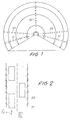
- Fig. 1 shows a system of lighting and obstacle detection installation according to the invention;
- Fig. 2 shows schematically and in plan view the functioning of the lighting system of Fig. 1 for the detection of obstacles;
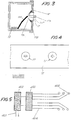
- Fig. 3 shows a detail of a suitable luminous spot;
- Fig. 4 is a partial local front view of two luminous spots;
- Fig. 5 shows an application scheme of the invention with a light source of laser diodes type;
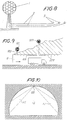
- Figs. 6 and 7 are cross-section views showing how the lighting system operates the detection of the hindrances or obstacles according to the invention;
- Fig. 8 shows a functional scheme of the auxiliary plant with a sun-light intercepting means;
- Fig. 9 shows an embodiment of the installation according to the system of Fig. 8;
- Fig. 10 shows a cross-section of the tunnel illuminated as above indicated; and
- Fig. 11 shows a modified embodiment with respect to that of Fig. 9.
- Fig. 1 shows an arrangement according to the invention for detecting the roadway pattern inside a tunnel and the possible presence of obstacles which may not be visible with a traditional type of lighting. The lighting according to the invention is obtained with at least a row of lights on one or both sides of the roadway for the purposes indicated below. The lights may be fed by individual local sources or by spaced apart sources feeding respective lights via optical fibers, also in conjunction with light generators located outside the tunnel.
- As can be seen in Fig. 1, two rows of
lights lights 35 may be predisposed for indicating the track of the tunnel. The two rows oflights 31 and/or 33, having lights relatively close to each other, are intended to ease the detection of the roadway pattern or track within the tunnel. The two rows oflights 31 allows the perception "in negative" of the presence of obstacles such as cars, whose height does not usually exceed 150 cm. In order to perceive the larger dimensions of vehicles of industrial type, the second row oflights 33 may be provided at the height of approximately 160 cm as above mentioned. Two types of obstacles can thus be distiguished depending whether they are made visible by the single row of lower lights or by both the rows of upper andlower lights - Advantageously, the lights of the
rows lights - Particularly useful for powering the lights of the subject installation is the use of a coherent light mostly of laser type; when supplied via optical fibers, such light may be advantageously a polarized light allowing a minor loss of energy along the optical fiber, as known from the technical literature in the field.
- Fig. 5 shows a supply system with an
electrical line 401 leading to a laser diodes-feeding supply 402 apt to feed energy to a laser diode system which defines a light source for theoptical fibers 404, the latter reaching the light-diffusion devices indicated by 405, which correspond to those indicated by 31, 33. - Shown in Fig. 3 is a possible embodiment of a light for illumination of the inside of a tunnel with the use of optical fibers which, however, may also be operated by individual, direct sources. Numeral 11 indicates a raceway apt to hold cables such as bundles of
fibers 13 or leads; the raceway may be disposed either on the surface or embedded in the wall of the tunnel along a row of lights. Numeral 15 indicates a lid - made up of a continuous structure or of discrete and intermittent sections - on which the lights are provided. One of these is indicated by 17 and is provided with aclamp 17A for clamping afiber 13A (or a cable) associated thereto, adevice 17B for the orientation of the light whose swiveling part 17C comprises theclamp 17A, thediffusion lens 17E (or the electro-optical transducer) and aprotection 17F. The light may be suitably oriented according to its required function. - Shown in Fig. 4 is a schematic arrangement for a plurality of
lights 17 which may be distributed along the raceway and the respective lid. - An auxiliary plant may be advantageously associated to the above installation, as previously mentioned, to avoid (during the day-time hours) an abrupt passage to the conditions of darkness and background illumination which the majority of vehicles' drivers must endure. This auxiliary plant is illustrated in Figs. 8 and 11.
- In the diagram of Fig. 8, numeral 1 indicates a system for intercepting the sun light, which may be of any type known from the technical literature of the pertinent technical field. Numeral 2 indicates optical fibers suitably disposed in bundles and fed with sun-derived light by the pick-up system 1 to feed
individual diffusers 3 inside the tunnel in which, therefore, there is no need of providing lighting equipment with electrical power supply. Fig. 9 illustrates an arrangement in which a tunnel G is supplied (starting from its entrance) with two or more sun-light picking up means 101, 201, etc., whoseoptical fibers 102, 202, etc., go into the tunnel up to different distances from the entrance of the same tunnel to illuminate subsequent regions of the tunnel by means of thediffusers diffusers - The sun energy-operated lighting plant may be installed at the same location of the main system.
- The sun-powered auxiliary plant is particularly suitable for illuminating the initial stretch of the tunnel starting from the entrance thereof, as the light intended for this form of illumination is substantially proportional to the amount of day-time light of which the interceting means, like those indicated by 1, 101 and 201, make use, while the lower picking-up capacity at dusk causes the additional lighting of the first length of the tunnel to become dim, when there is less need of such a lighting insofar as the external light is lower and so is the illumination gradient at the entrance of the tunnel.
- The schematic representation in Fig. 11 shows an arrangement in which, owing to the steep slope of the ground at the entrance of the tunnel G, only one lighting system can be operated, starting from the same entrance of the tunnel, by means of an
interceptor 301 and bundles offibers 302 which allow an illumination withlights 303 extending over a relatively limited length inside the tunnel, because of the limited operating range of the optical fibers. In this case, provision may also be made for an integration of the sun light through other illumination means which may also be derived from outside the tunnel and with the aid of an optical-fiber transmission as well. - It is understood that the drawing shows an exemplification given only as a practical demonstration of the invention, as this may vary in the forms and dispositions without nevertheless coming out from the scope of the idea on which the invention is based.
Claims (14)
1) Background lighting installation within motorway tunnels for the perception of the track and the possible presence of obstacles along the roadway, characterized in that it comprises at least a row of luminous spots substantially close to each other along each side of the tunnel, said lights defining the track of the same tunnel, while the interruption of the spots of one row indicates in reverse mode the presence of an obstacle causing such interruption.
2) Lighting installation according to the preceding claim, characterized in that it comprises on each side at least two rows of luminous spots at two different heights of the order of 80 and 160 cm from the roadway to ease the perception of the obstacle dimensions.
3) Lighting installation according to any preceding claim, characterized in that the light of the luminous spots is substantially punctiform and is a coherent light, mostly of laser type.
4) Lighting installation according to any preceding claim, characterized in that the light at the luminous spots is a polarized laser light which is transmitted via optical fibers and obtained by remote generators which may be arranged outside the tunnel inside which, therefore, no electrical leads are provided.
5) Lighting installation according to any preceding claim, characterized in that the luminous spots for one-way tunnels are oriented towards the incoming vehicle and are swivellingly adjustable.
6) Lighting installation according to at least one of claims 1 to 3 and 5, characterized in that it comprises a third longitudinal row of luminous spots substantially along the vertex of the tunnel, which are oriented towards the driver.
7) Lighting installation according to any preceding claim, characterized in that it is associated with an auxiliary lighting plant for a day-time illumination gradually becoming dim inside the tunnels starting from the entrance thereof, to avoid the sudden passage from conditions of natural, external illumination to substantial darkness with background illumination only, and to allow for a gradual adaptation of the eye.
8) Lighting installation according to claim 7, characterized in that said auxiliary plant comprises: at least a sun-light intercepting unit outside the tunnel; bundles of optical fibers coupled to the lenses of the interceptors and extending inside the tunnel; and optical diffusers fed with light energy from optical fibers and able to illuminate the initial stretch of the tunnel starting from the entrance thereof.
9) Lighting installation according to claims 7 and 8, characterized in that the diffusers are so oriented as to meet the illumination requirements.
10) Lighting installation according to any one of claims 7 to 9, characterized in that the loss of energy along the optical fibers is at least partly exploited for gradually attenuating the illumination as a function of the distance from the entrance.
11) Lighting installation according to any one of claims 7 to 10, characterized in that solar interceptors are disposed at least close to the entrance of the tunnel and that the optical fibers go into the gallery from the entrance thereof.
12) Lighting installation according to any one of claims 7 to 10 and possibly 11, characterized in that the solar interceptors are disposed along the ground work to reach the tunnel through the vault thereof.
13) Lighting installation according to any one of claims 7 to 12, characterized in that the sun-light interceptors are of swiveling type to follow the sun.
14) Lighting installation according to any one of claims 7 to 13, characterized in that it comprises auxiliary generators generating a light energy other than the solar one.
Applications Claiming Priority (2)
| Application Number | Priority Date | Filing Date | Title |
|---|---|---|---|
| ITFI910265 | 1991-11-05 | ||
| ITFI910265A IT1252895B (en) | 1991-11-05 | 1991-11-05 | LIGHTING SYSTEM FOR HIGHWAY TUNNELS |
Publications (2)
| Publication Number | Publication Date |
|---|---|
| EP0543783A2 true EP0543783A2 (en) | 1993-05-26 |
| EP0543783A3 EP0543783A3 (en) | 1996-02-28 |
Family
ID=11349833
Family Applications (1)
| Application Number | Title | Priority Date | Filing Date |
|---|---|---|---|
| EP92830611A Withdrawn EP0543783A3 (en) | 1991-11-05 | 1992-11-05 | Lighting installation for motorway tunnels |
Country Status (2)
| Country | Link |
|---|---|
| EP (1) | EP0543783A3 (en) |
| IT (1) | IT1252895B (en) |
Cited By (6)
| Publication number | Priority date | Publication date | Assignee | Title |
|---|---|---|---|---|
| FR2745308A1 (en) * | 1996-02-28 | 1997-08-29 | Vezon Paul | Illumination line marking system for marking lanes on road surface indicating pavement partition at night |
| EP2148129A1 (en) * | 2008-07-21 | 2010-01-27 | Thorn Europhane S.A. | System for lighting a tunnel or an underpass |
| NL2002408C2 (en) * | 2008-11-12 | 2010-05-17 | Ind Tech Verlichting B V | LEDS PROVIDED LIGHTING DEVICE FOR A TUNNEL. |
| CN102518448A (en) * | 2011-12-09 | 2012-06-27 | 武汉理工大学 | Tunnel grating system for changing speed perception of driver and method for controlling same |
| CN107513952A (en) * | 2017-07-27 | 2017-12-26 | 杭州胜为科技有限公司 | Method for setting photoelectric induction system of expressway tunnel |
| CN108870212A (en) * | 2018-08-20 | 2018-11-23 | 广西南宁都市阳光照明工程有限公司 | A kind of Tunnel Lamp installation system and installation method |
Families Citing this family (1)
| Publication number | Priority date | Publication date | Assignee | Title |
|---|---|---|---|---|
| CN109024344B (en) * | 2018-08-01 | 2020-05-05 | 武汉理工大学 | Multi-level asymmetric urban tunnel curve road section sight line induction system |
Citations (6)
| Publication number | Priority date | Publication date | Assignee | Title |
|---|---|---|---|---|
| DE1124894B (en) * | 1958-05-24 | 1962-03-08 | Siemens Ag | Lighting arrangement for traffic tunnels |
| FR1529977A (en) * | 1966-06-04 | 1968-06-21 | Philips Nv | Tunnel lighting installation |
| DE2246963A1 (en) * | 1972-09-25 | 1974-04-18 | Siemens Ag | LIGHTING SYSTEM FOR A TRAFFIC TUNNEL |
| CH598536A5 (en) * | 1975-07-16 | 1978-04-28 | Novelectric Ag | Traffic tunnel lighting system with discharge lamps |
| US4297000A (en) * | 1979-01-11 | 1981-10-27 | Fries James E | Solar lighting system |
| EP0127900A1 (en) * | 1983-06-06 | 1984-12-12 | Kei Mori | A method for illuminating a tunnel of a highway |
-
1991
- 1991-11-05 IT ITFI910265A patent/IT1252895B/en active IP Right Grant
-
1992
- 1992-11-05 EP EP92830611A patent/EP0543783A3/en not_active Withdrawn
Patent Citations (6)
| Publication number | Priority date | Publication date | Assignee | Title |
|---|---|---|---|---|
| DE1124894B (en) * | 1958-05-24 | 1962-03-08 | Siemens Ag | Lighting arrangement for traffic tunnels |
| FR1529977A (en) * | 1966-06-04 | 1968-06-21 | Philips Nv | Tunnel lighting installation |
| DE2246963A1 (en) * | 1972-09-25 | 1974-04-18 | Siemens Ag | LIGHTING SYSTEM FOR A TRAFFIC TUNNEL |
| CH598536A5 (en) * | 1975-07-16 | 1978-04-28 | Novelectric Ag | Traffic tunnel lighting system with discharge lamps |
| US4297000A (en) * | 1979-01-11 | 1981-10-27 | Fries James E | Solar lighting system |
| EP0127900A1 (en) * | 1983-06-06 | 1984-12-12 | Kei Mori | A method for illuminating a tunnel of a highway |
Cited By (7)
| Publication number | Priority date | Publication date | Assignee | Title |
|---|---|---|---|---|
| FR2745308A1 (en) * | 1996-02-28 | 1997-08-29 | Vezon Paul | Illumination line marking system for marking lanes on road surface indicating pavement partition at night |
| EP2148129A1 (en) * | 2008-07-21 | 2010-01-27 | Thorn Europhane S.A. | System for lighting a tunnel or an underpass |
| NL2002408C2 (en) * | 2008-11-12 | 2010-05-17 | Ind Tech Verlichting B V | LEDS PROVIDED LIGHTING DEVICE FOR A TUNNEL. |
| CN102518448A (en) * | 2011-12-09 | 2012-06-27 | 武汉理工大学 | Tunnel grating system for changing speed perception of driver and method for controlling same |
| CN102518448B (en) * | 2011-12-09 | 2013-04-24 | 武汉理工大学 | Tunnel grating system for changing speed perception of driver |
| CN107513952A (en) * | 2017-07-27 | 2017-12-26 | 杭州胜为科技有限公司 | Method for setting photoelectric induction system of expressway tunnel |
| CN108870212A (en) * | 2018-08-20 | 2018-11-23 | 广西南宁都市阳光照明工程有限公司 | A kind of Tunnel Lamp installation system and installation method |
Also Published As
| Publication number | Publication date |
|---|---|
| EP0543783A3 (en) | 1996-02-28 |
| ITFI910265A0 (en) | 1991-11-05 |
| IT1252895B (en) | 1995-07-05 |
| ITFI910265A1 (en) | 1993-05-05 |
Similar Documents
| Publication | Publication Date | Title |
|---|---|---|
| US6092318A (en) | Solar battery type indication apparatus | |
| ATE348025T1 (en) | SIDE INDICATOR LIGHT | |
| EP0376056A3 (en) | Optical multiplexed electrical distribution system particularly suited for vehicles | |
| GB2128664A (en) | Luminous indicating device for road markings | |
| US6031468A (en) | Warning light adapted for use with a stop sign | |
| KR900012113A (en) | Solar lighting equipment | |
| EP0543783A2 (en) | Lighting installation for motorway tunnels | |
| JP2002260401A (en) | Outside lane lighting system | |
| KR900001115Y1 (en) | Method and apparatus for illuminating a stop inside of a tunnel | |
| JP2003535242A (en) | Road display system | |
| GB2076042A (en) | Traffic markers | |
| KR101939632B1 (en) | Pavement marker and road direction guide system using the same | |
| KR100806209B1 (en) | Luminous apparatus for over-speed prevention | |
| KR101030282B1 (en) | Controller of load pilot lamp having a function of alteration color | |
| JP2005517836A (en) | Road marking system | |
| JP2011184864A (en) | Visual guidance device | |
| KR200399041Y1 (en) | Indication equipment for boundary stone in a unit | |
| KR102357183B1 (en) | Lighting sign board | |
| CN213024653U (en) | Intelligent spike warning device | |
| KR101447594B1 (en) | Lighting devices | |
| CN105544421A (en) | Automatic control type light-emitting road delineator control system | |
| KR101462971B1 (en) | Lighting devices | |
| KR20210071756A (en) | A safety sign device for central separator using solar generation | |
| GB2314107A (en) | Road visibility system | |
| KR200221491Y1 (en) | lighting apparatus with optical fiber |
Legal Events
| Date | Code | Title | Description |
|---|---|---|---|
| PUAI | Public reference made under article 153(3) epc to a published international application that has entered the european phase |
Free format text: ORIGINAL CODE: 0009012 |
|
| AK | Designated contracting states |
Kind code of ref document: A2 Designated state(s): AT BE CH DE DK ES FR GB GR IE IT LI LU MC NL PT |
|
| PUAL | Search report despatched |
Free format text: ORIGINAL CODE: 0009013 |
|
| AK | Designated contracting states |
Kind code of ref document: A3 Designated state(s): AT BE CH DE DK ES FR GB GR IE IT LI LU MC NL PT |
|
| STAA | Information on the status of an ep patent application or granted ep patent |
Free format text: STATUS: THE APPLICATION IS DEEMED TO BE WITHDRAWN |
|
| 18D | Application deemed to be withdrawn |
Effective date: 19960531 |