EP0544581A1 - One piece connector for fluid circuits, especially for medical use - Google Patents
One piece connector for fluid circuits, especially for medical use Download PDFInfo
- Publication number
- EP0544581A1 EP0544581A1 EP92403158A EP92403158A EP0544581A1 EP 0544581 A1 EP0544581 A1 EP 0544581A1 EP 92403158 A EP92403158 A EP 92403158A EP 92403158 A EP92403158 A EP 92403158A EP 0544581 A1 EP0544581 A1 EP 0544581A1
- Authority
- EP
- European Patent Office
- Prior art keywords
- connector
- needle
- upstream
- plug
- connector according
- Prior art date
- Legal status (The legal status is an assumption and is not a legal conclusion. Google has not performed a legal analysis and makes no representation as to the accuracy of the status listed.)
- Granted
Links
Images


Classifications
-
- A—HUMAN NECESSITIES
- A61—MEDICAL OR VETERINARY SCIENCE; HYGIENE
- A61M—DEVICES FOR INTRODUCING MEDIA INTO, OR ONTO, THE BODY; DEVICES FOR TRANSDUCING BODY MEDIA OR FOR TAKING MEDIA FROM THE BODY; DEVICES FOR PRODUCING OR ENDING SLEEP OR STUPOR
- A61M39/00—Tubes, tube connectors, tube couplings, valves, access sites or the like, specially adapted for medical use
- A61M39/02—Access sites
- A61M39/04—Access sites having pierceable self-sealing members
- A61M39/045—Access sites having pierceable self-sealing members pre-slit to be pierced by blunt instrument
-
- A—HUMAN NECESSITIES
- A61—MEDICAL OR VETERINARY SCIENCE; HYGIENE
- A61M—DEVICES FOR INTRODUCING MEDIA INTO, OR ONTO, THE BODY; DEVICES FOR TRANSDUCING BODY MEDIA OR FOR TAKING MEDIA FROM THE BODY; DEVICES FOR PRODUCING OR ENDING SLEEP OR STUPOR
- A61M39/00—Tubes, tube connectors, tube couplings, valves, access sites or the like, specially adapted for medical use
- A61M2039/0036—Tubes, tube connectors, tube couplings, valves, access sites or the like, specially adapted for medical use characterised by a septum having particular features, e.g. having venting channels or being made from antimicrobial or self-lubricating elastomer
-
- A—HUMAN NECESSITIES
- A61—MEDICAL OR VETERINARY SCIENCE; HYGIENE
- A61M—DEVICES FOR INTRODUCING MEDIA INTO, OR ONTO, THE BODY; DEVICES FOR TRANSDUCING BODY MEDIA OR FOR TAKING MEDIA FROM THE BODY; DEVICES FOR PRODUCING OR ENDING SLEEP OR STUPOR
- A61M39/00—Tubes, tube connectors, tube couplings, valves, access sites or the like, specially adapted for medical use
- A61M39/02—Access sites
- A61M39/04—Access sites having pierceable self-sealing members
- A61M2039/042—Shrouds encircling the access needle preventing accidental needle-stick
-
- A—HUMAN NECESSITIES
- A61—MEDICAL OR VETERINARY SCIENCE; HYGIENE
- A61M—DEVICES FOR INTRODUCING MEDIA INTO, OR ONTO, THE BODY; DEVICES FOR TRANSDUCING BODY MEDIA OR FOR TAKING MEDIA FROM THE BODY; DEVICES FOR PRODUCING OR ENDING SLEEP OR STUPOR
- A61M39/00—Tubes, tube connectors, tube couplings, valves, access sites or the like, specially adapted for medical use
- A61M39/10—Tube connectors; Tube couplings
- A61M2039/1066—Tube connectors; Tube couplings having protection means, e.g. sliding sleeve to protect connector itself, shrouds to protect a needle present in the connector, protective housing, isolating sheath
-
- A—HUMAN NECESSITIES
- A61—MEDICAL OR VETERINARY SCIENCE; HYGIENE
- A61M—DEVICES FOR INTRODUCING MEDIA INTO, OR ONTO, THE BODY; DEVICES FOR TRANSDUCING BODY MEDIA OR FOR TAKING MEDIA FROM THE BODY; DEVICES FOR PRODUCING OR ENDING SLEEP OR STUPOR
- A61M39/00—Tubes, tube connectors, tube couplings, valves, access sites or the like, specially adapted for medical use
- A61M39/10—Tube connectors; Tube couplings
- A61M2039/1072—Tube connectors; Tube couplings with a septum present in the connector
-
- A—HUMAN NECESSITIES
- A61—MEDICAL OR VETERINARY SCIENCE; HYGIENE
- A61M—DEVICES FOR INTRODUCING MEDIA INTO, OR ONTO, THE BODY; DEVICES FOR TRANSDUCING BODY MEDIA OR FOR TAKING MEDIA FROM THE BODY; DEVICES FOR PRODUCING OR ENDING SLEEP OR STUPOR
- A61M39/00—Tubes, tube connectors, tube couplings, valves, access sites or the like, specially adapted for medical use
- A61M39/22—Valves or arrangement of valves
- A61M39/26—Valves closing automatically on disconnecting the line and opening on reconnection thereof
- A61M2039/267—Valves closing automatically on disconnecting the line and opening on reconnection thereof having a sealing sleeve around a tubular or solid stem portion of the connector
-
- Y—GENERAL TAGGING OF NEW TECHNOLOGICAL DEVELOPMENTS; GENERAL TAGGING OF CROSS-SECTIONAL TECHNOLOGIES SPANNING OVER SEVERAL SECTIONS OF THE IPC; TECHNICAL SUBJECTS COVERED BY FORMER USPC CROSS-REFERENCE ART COLLECTIONS [XRACs] AND DIGESTS
- Y10—TECHNICAL SUBJECTS COVERED BY FORMER USPC
- Y10S—TECHNICAL SUBJECTS COVERED BY FORMER USPC CROSS-REFERENCE ART COLLECTIONS [XRACs] AND DIGESTS
- Y10S604/00—Surgery
- Y10S604/905—Aseptic connectors or couplings, e.g. frangible, piercable
Definitions
- the invention relates to a unitary composite connector for a liquid circuit, in particular for medical use.
- unitary means that the connector is constituted by a permanent assembly, unlike certain prior connectors made up of at least two separate assemblies which are assembled when establishing the connection.
- a connector of the type which comprises means which constitute a tubular chamber between an upstream connector and a downstream connector situated at opposite ends of the chamber and fixed relative to each other, said downstream connector constituting a passage; a hollow needle fixed in the chamber and capable of making the upstream connection communicate with the downstream connection; a plug capable of being traversed by the needle, mounted in the passage of the downstream connector so as to be able to slide between a stable downstream closure position where it closes said passage and is not crossed by the needle and an upstream position where it is traversed by said needle and towards which it can be pushed by a member inserted from outside the connector in said passage, and a means located in the chamber and which resiliently pushes the stopper towards the stable position of obturation, the material of the plug being such that the plug covers its sealing properties when it is no longer crossed by the needle.
- Such a unitary composite connector is particularly useful in the medical field, for example for introducing a liquid into the body of a patient and various embodiments have been described, in particular in documents EP 0309771 and US-A-4,998,927 .
- An object of the invention is to provide a new unitary composite connector of the type described above, capable of producing a reliable and efficient connection, which is of acceptable manufacturing cost, especially if the connector must be discarded after use and which does not present any risk of contamination of the liquid circuit, especially in the region of its downstream connection.
- said passage of the downstream connection has an outlet opening completely filled with the material of the plug when the latter is in a stable shutter position, which avoids any dead volume around the plug in this opening and therefore the risks of contamination which would be linked to the presence of a dead volume and in that the means which pushes the plug back towards its closed position is a spring.
- Figure 1 shows the constituent parts of a first embodiment of a connector of the invention.
- the casing 1 delimits a tubular chamber 6 between a downstream end 7 which is shaped to constitute a downstream connection and an upstream end 8 which is shaped to receive the upstream connector 2.
- the chamber 6 has two zones 6a, 6b of different diameters.
- the upstream connector 2 has a central channel 9 which frictionally receives the needle 3 so that when this connector is mounted on the casing, the needle penetrates axially into the chamber in the direction of the downstream connector.
- the downstream connection 7 constitutes a passage 7b of frustoconical shape, the outlet opening 7a of this passage having a diameter slightly larger than that of its inlet opening 7c.
- This type of passage is designed in a manner known per se for the introduction of a tip 12 has corresponding male taper.
- the plug 4, the chamber 6 and the passage 7b are shaped so that the plug can slide in the chamber and the passage with lateral sealing, between a downstream position (fig. 2) and an upstream position (fig. 3).
- the plug is a cylindrical block of elastomeric material which has a downstream end 4a capable of sliding in the passage 7b with lateral sealing and an upstream end 4b of larger diameter capable of sliding in the chamber 6 with lateral sealing.
- the upstream end is preceded by a tail 4c which is used for mounting the spring 5, which abuts against the upstream end.
- the needle In the downstream position (fig. 2), the needle enters the plug but the bevelled opening 10 of the needle remains embedded in the plug, the material of which closes this opening.
- the plug is therefore a shutter since it is not crossed right through and it prohibits communication between the upstream and downstream connections.
- the stopper In the upstream position (fig. 3), the stopper has moved back towards the needle until completely clearing the passage 7b of the downstream connection and being completely crossed by the bevelled opening of the needle, which is then beyond of the plug: in this position, the upstream and downstream connections communicate by the needle.
- the spring 5 is housed in the chamber 6 between the upstream connector 2 on which it bears and the plug 4 which it pushes towards its downstream position where the plug is in abutment against a shoulder formed by an internal annular rim 11 of the bedroom.
- the spring is chosen to allow a stroke of the plug sufficient for the plug to retreat against the action of the spring into the appropriate upstream position.
- the passage of the downstream connection and the end piece have female and male taper respectively which allow the end piece to be held by friction in the connection.
- the plug automatically returns to the closed position under the action of the spring.
- the material of the stopper is such that the stopper recovers its sealing properties when it is no longer passed through by the needle. Such materials are known in this application and do not need to be described in detail.
- the plug in the closed position completely fills the outlet opening 7a with the conical passage of the downstream connector and, advantageously, the plug has a slightly curved end projecting from this outlet opening of the connector (FIG. 2).
- the upstream connector 2 is of any suitable type and generally constitutes a male connector.
- Fig. 4 shows an embodiment in which the needle 3 is a simple tube the end of which is embedded in the material of the stopper and does not have a bevel and in which the stopper 4 has a downstream end 4a provided with a longitudinal pre-perforation 4th in so that at rest, that is to say when this end is not stressed by the needle, the pre-perforation 4e is closed on itself (fig. 4A) while under the stress of the needle when the cap is pushed towards the needle by an external element, for example the end of a syringe S, the pre-perforation opens gradually to let the needle pass (fig 4B and 4C) in a manner known per se.
- the pre-perforation has any desired shape.
- it has a cross-section in the form of a cross (fig. 5) or a point (fig. 6).
- the plug shown in fig. 4 has a cylindrical end 4a whose diameter is greater than the diameter of the outlet opening 7a of the passage 7b, which is greater than that of the inlet opening 7c of this passage: it follows that the spring 5 must be chosen with sufficient force to force the stopper towards its closed position (fig. 4A). The end of the plug is thus compressed laterally in the downstream connector 7 which ensures the lateral tightness of the connector.
- Figs. 7 to 9 show embodiments in which the plug has a front face 4d, concave (fig. 7), flat (fig. 8) or convex (fig 9) and one end 4a of decreasing frustoconical shape from the front face 4d .
- the taper of this end corresponds substantially to the internal taper of the downstream connector 7.
- Figs. 10 to 12 show embodiments in which the plug has a concave front face 4d (fig. 10), flat (fig. 11) or convex (fig. 12) but where the end of the plug 4a is cylyndrique.
- a convex front face (figs 2, 4, 9, 12) facilitates the forced insertion of the plug into the passage of the downstream connection under the thrust of the spring
- a concave front face (figs. 7, 10) offers a better possibility for decontamination
- a conical shape (figs 7 -9) reduces the friction forces when the plug reaches the end of the stroke under the pressure of the spring, that is to say when the force of the spring has become weaker.
- the invention is not limited to a particular choice for upstream and downstream connections, this choice depending on the conditions of use of the connector.
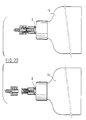
- FIGS 13 and following show, by way of non-limiting examples, connectors according to the invention comprising various fittings. Some figures are double and respectively show the connector at rest (no communication) or in service (communication).
- upstream and downstream have been used to designate relative positions in the direction from the needle to the stopper.
- the liquid will generally flow in the opposite direction so that if one took as direction of reference the direction of flow of the liquid, it would be necessary to reverse the expressions: the downstream connection should be designated as being the upstream connection, the outlet opening of the passage of this fitting should be considered as an inlet opening, etc.
Abstract
Description
L'invention concerne un connecteur composite unitaire pour circuit de liquide, notamment à usage médical.The invention relates to a unitary composite connector for a liquid circuit, in particular for medical use.
L'expression "unitaire" signifie que le connecteur est constitué par un assemblage permanent, au contraire de certains connecteurs antérieurs constitués d'au moins deux ensembles séparés que l'on assemble au moment d'établir la connection.The expression "unitary" means that the connector is constituted by a permanent assembly, unlike certain prior connectors made up of at least two separate assemblies which are assembled when establishing the connection.
Elle concerne plus particulièrement un connecteur du type qui comprend des moyens qui constituent une chambre tubulaire entre un raccord amont et un raccord aval situés à des extrémités opposées de la chambre et fixes l'un par rapport à l'autre, ledit raccord aval constituant un passage; une aiguille creuse fixe dans la chambre et apte à faire communiquer le raccord amont avec le raccord aval ; un bouchon apte à être traversé par l'aiguille, monté dans le passage du raccord aval de façon à pouvoir coulisser entre une position aval stable d'obturation où il obture ledit passage et n'est pas traversé par l'aiguille et une position amont où il est traversé par ladite aiguille et vers laquelle il peut être poussé par un organe introduit depuis l'extérieur du connecteur dans ledit passage, et un moyen situé dans la chambre et qui repousse élastiquement le bouchon vers la position stable d'obturation, la matière du bouchon étant telle que le bouchon recouvre ses propriétés d'obturation lorsqu'il n'est plus traversé par l'aiguille.It relates more particularly to a connector of the type which comprises means which constitute a tubular chamber between an upstream connector and a downstream connector situated at opposite ends of the chamber and fixed relative to each other, said downstream connector constituting a passage; a hollow needle fixed in the chamber and capable of making the upstream connection communicate with the downstream connection; a plug capable of being traversed by the needle, mounted in the passage of the downstream connector so as to be able to slide between a stable downstream closure position where it closes said passage and is not crossed by the needle and an upstream position where it is traversed by said needle and towards which it can be pushed by a member inserted from outside the connector in said passage, and a means located in the chamber and which resiliently pushes the stopper towards the stable position of obturation, the material of the plug being such that the plug covers its sealing properties when it is no longer crossed by the needle.
Un tel connecteur composite unitaire est notamment utile dans le domaine médical, par exemple pour introduire un liquide dans le corps d'un patient et diverses réal¡sations en ont été décrites, notamment dans les documents EP 0309771 et US-A-4 998 927.Such a unitary composite connector is particularly useful in the medical field, for example for introducing a liquid into the body of a patient and various embodiments have been described, in particular in documents EP 0309771 and US-A-4,998,927 .
Ces publications mettent en évidence qu'il est difficile d'obtenir un connecteur composite unitaire qui soit d'un coût de fabrication acceptable, qui assure un raccordement fiable et efficace et qui soit exempt de risques de contamination.These publications show that it is difficult to obtain a unitary composite connector which is of an acceptable manufacturing cost, which ensures a reliable and efficient connection and which is free from risks of contamination.
Un but de l'invention est de fournir un nouveau connecteur composite unitaire du type décrit ci-dessus, apte à réaliser un raccordement fiable et efficace, qui soit d'un coût de fabrication acceptable, notamment si le connecteur doit être jeté après usage et qui ne présente pas de risques de contamination du circuit liquide, notamment dans la région de son raccord aval.An object of the invention is to provide a new unitary composite connector of the type described above, capable of producing a reliable and efficient connection, which is of acceptable manufacturing cost, especially if the connector must be discarded after use and which does not present any risk of contamination of the liquid circuit, especially in the region of its downstream connection.
On y parvient selon l'invention par le fait que ledit passage du raccord aval a une ouverture de sortie totalement remplie par la matière du bouchon lorsque ce dernier est en position stable d'obturation, ce qui évite tout volume mort autour du bouchon dans cette ouverture et donc les risques de contamination qui seraient liés à la présence d'un volume mort et en ce que le moyen qui repousse le bouchon vers sa position d'obturation est un ressort.This is achieved according to the invention by the fact that said passage of the downstream connection has an outlet opening completely filled with the material of the plug when the latter is in a stable shutter position, which avoids any dead volume around the plug in this opening and therefore the risks of contamination which would be linked to the presence of a dead volume and in that the means which pushes the plug back towards its closed position is a spring.
Le fait d'utiliser un ressort pour repousser le bouchon, alors que les antérirités utilisent une déformation élastique d'une partie tubulaire du bouchon est très important car il permet de choisir à volonté la force de rappel du ressort et d'utiliser un bouchon introduit à force dans le raccord aval en sorte que la compression latérale du bouchon dans le raccord garantisse une bonne étanchéité, le ressort choisi ayant une force suffisante pour pousser le bouchon dans le raccord malgré le frottement du bouchon dans le raccord du à la compression latérale du bouchon.The fact of using a spring to push back the stopper, while the anterities use an elastic deformation of a tubular part of the stopper is very important because it allows to choose at will the return force of the spring and to use a inserted stopper by force in the downstream fitting so that the lateral compression of the plug in the fitting guarantees a good seal, the spring chosen having sufficient force to push the plug into the fitting despite the friction of the plug in the fitting due to the lateral compression of the plug.
On décrira ci-après différentes réalisations d'un tel connecteur, à titre d'exemples préférés mais non limitatifs, en référence aux figures du dessin joint sur lequel :
- la figure 1 est une vue éclatée des pièces constitutives d'un connecteur selon l'invention ;
- la figure 2 est une coupe axiale du connecteur en état d'obturation;
- la figure 3 est une coupe axiale du connecteur en état de non-obturation;
- la figure 4 est une coupe axiale d'une variante de connecteur selon l'invention, pour trois positions du bouchon (figs 4A, 4B, 4C) ;
- les figures 5 et 6 sont des vues de face de l'extrémité du bouchon dans le raccord aval dans deux exemples de réalisation ;
- les figures 7 à 12 sont des coupes axiales du bouchon selon différents exemples de réalisation, et
- les figures 13 à 20 sont des coupes montrant différentes réalisations de connecteurs conformes à l'invention.
- Figure 1 is an exploded view of the component parts of a connector according to the invention;
- Figure 2 is an axial section of the connector in the closed state;
- Figure 3 is an axial section of the connector in non-sealing state;
- Figure 4 is an axial section of a connector variant according to the invention, for three positions of the plug (Figs 4A, 4B, 4C);
- Figures 5 and 6 are front views of the end of the plug in the downstream connector in two exemplary embodiments;
- FIGS. 7 to 12 are axial sections of the plug according to different exemplary embodiments, and
- Figures 13 to 20 are sections showing different embodiments of connectors according to the invention.
La figure 1 montre les parties constitutives d'un premier exemple de réalisation d'un connecteur de l'invention.Figure 1 shows the constituent parts of a first embodiment of a connector of the invention.
Ce connecteur est un corps rigide constitué par la combinaison de cinq pièces, à savoir :
- un
carter 1 non déformable, - un
raccord amont 2, - une
aiguille 3, - un bouchon d'obturation 4, et
- un ressort hélicoïdal 5.
- a non-deformable
casing 1, - an
upstream connection 2, - a
needle 3, - a
closure plug 4, and - a
coil spring 5.
Ces pièces sont assemblées en un ensemble unitaire (figure 2) tenant compte des particularités suivantes.These parts are assembled into a unitary assembly (Figure 2) taking into account the following particularities.
Le carter 1 délimite une chambre tubulaire 6 entre une extrémité aval 7 qui est conformée pour constituer un raccord aval et une extrémité amont 8 qui est conformée pour recevoir le raccord amont 2. Dans cet exemple, la chambre 6 comporte deux zones 6a, 6b de diamètres différents.The
Le raccord amont 2 présente en canal central 9 qui reçoit à friction l'aiguille 3 en sorte que lorsque ce raccord est monté sur le carter, l'aiguille pénètre axialement dans la chambre en direction du raccord aval.The
Le raccord aval 7 constitue un passage 7b de forme tronconique, l'ouverture de sortie 7a de ce passage ayant un diamètre légèrement plus grand que celui de son ouverture d'entrée 7c. Ce type de passage est conçu de façon en soi connue pour l'introduction d'un embout 12 a conicité mâle correspondante.The
Le bouchon 4, la chambre 6 et le passage 7b sont conformés pour que le bouchon puisse coulisser dans la chambre et le passage avec étanchéité latérale, entre une position aval (fig. 2) et une position amont (fig. 3).The
De fait, le bouchon est un bloc cylindrique en matériau élastomère qui présente une extrémité aval 4a apte à coulisser dans le passage 7b avec étanchéité latérale et une extrémité amont 4b de plus grand diamètre apte à coulisser dans la chambre 6 avec étanchéité latérale. L'extrémité amont est précédée d'une queue 4c qui sert au montage du ressort 5, lequel vient en butée contre l'extrémité amont.In fact, the plug is a cylindrical block of elastomeric material which has a
Dans la position aval (fig. 2), l'aiguille pénètre dans le bouchon mais l'ouverture biseautée 10 de l'aiguille reste noyée dans le bouchon dont la matière obture cette ouverture. Le bouchon est donc obturateur puisqu'il n'est pas traversé de part en part et il interdit la communication entre les raccords amont et aval.In the downstream position (fig. 2), the needle enters the plug but the
Dans la position amont (fig. 3), le bouchon a reculé vers l'aiguille jusqu'à dégager totalement le passage 7b du raccord aval et être totalement traversé par l'ouverture biseautée de l'aiguille, qui se trouve alors au-delà du bouchon : dans cette position, les raccords amont et aval communiquent par l'aiguille.In the upstream position (fig. 3), the stopper has moved back towards the needle until completely clearing the
Le ressort 5 est logé dans la chambre 6 entre le raccord amont 2 sur lequel il prend appui et le bouchon 4 qu'il pousse vers sa position aval où le bouchon se trouve en butée contre un épaulement constitué par un rebord annulaire interne 11 de la chambre.The
Le ressort est choisi pour autoriser une course du bouchon suffisante pour que le bouchon puisse reculer contre l'action du ressort jusque dans la position amont qui convient.The spring is chosen to allow a stroke of the plug sufficient for the plug to retreat against the action of the spring into the appropriate upstream position.
Ce recul est provoqué par exemple par l'introduction d'un embout S dans le passage conique du raccord aval, par exemple l'extrémité d'une seringue (figures 2 et 3).This decline is caused for example by the introduction of a tip S in the conical passage of the downstream connector, for example the end of a syringe (Figures 2 and 3).
Le passage du raccord aval et l'embout présentent des conicités respectivement femelle et mâle qui permettent le maintien par friction de l'embout dans le raccord.The passage of the downstream connection and the end piece have female and male taper respectively which allow the end piece to be held by friction in the connection.
Si l'on retire l'embout, le bouchon revient automatiquement en position d'obturation sous l'action du ressort. La matière du bouchon est telle que le bouchon recouvre ses propriétés d'obturation lorsqu'il n'est plus traversé par l'aiguille. De tels matériaux, sont connus dans cette application et n'ont pas besoin d'être décrits en détails.If the end piece is removed, the plug automatically returns to the closed position under the action of the spring. The material of the stopper is such that the stopper recovers its sealing properties when it is no longer passed through by the needle. Such materials are known in this application and do not need to be described in detail.
Le bouchon en position d'obturation remplit intégralement l'ouverture de sortie 7a du passage conique du raccord aval et, avantageusement, le bouchon présente une extrémité légèrement bombée en saillie hors de cette ouverture de sortie du raccord (figure 2).The plug in the closed position completely fills the outlet opening 7a with the conical passage of the downstream connector and, advantageously, the plug has a slightly curved end projecting from this outlet opening of the connector (FIG. 2).
On évite ainsi les risques d'introduction d'éléments contaminants dans le passage du raccord lorsque le bouchon est en position d'obturation.This avoids the risk of introducing contaminants into the passage of the fitting when the plug is in shutter position.
Le raccord amont 2 est de tout type approprié et constitue généralement un raccord mâle.The
La fig. 4 montre une réalisation dans laquelle l'aiguille 3 est un simple tube dont l'extrémité est noyée dans la matière du bouchon et ne comporte pas de biseau et dans laquelle le bouchon 4 comporte une extrémité aval 4a munie d'une préperforation longitudinale 4e en sorte qu'au repos, c'est-à-dire lorsque cette extrémité n'est pas sollicitée par l'aiguille, la préperforation 4e est fermée sur elle-même (fig. 4A) tandis que sous la sollicitation de l'aiguille lorsque le bouchon est poussé vers l'aiguille par un élément extérieur, par exemple l'extrémité d'une seringue S, la préperforation s'ouvre progressivement pour laisser passer l'aiguille (fig 4B et 4C) de façon en soi connue.Fig. 4 shows an embodiment in which the
La préperforation a toute forme désirée. Par exemple elle a en section droite transversale la forme d'une croix (fig. 5) ou d'un point (fig. 6).The pre-perforation has any desired shape. For example, it has a cross-section in the form of a cross (fig. 5) or a point (fig. 6).
Le bouchon représenté sur la fig. 4 présente une extrémité cylindrique 4a dont le diamètre est supérieur au diamètre de l'ouverture de sortie 7a du passage 7b, lequel est supérieur à celui de l'ouverture d'entrée 7c de ce passage : il en résulte que le ressort 5 doit être choisi avec une force suffisante pour pousser à force le bouchon vers sa position d'obturation (fig. 4A). L'extrémité du bouchon est ainsi comprimée latéralement dans le raccord aval 7 ce qui assure l'étanchéité latérale du raccord.The plug shown in fig. 4 has a
Les fig. 7 à 9 montrent des réalisations dans lesquelles le bouchon présente une face avant 4d, concave (fig. 7), plate (fig. 8) ou convexe (fig 9) et une extrémité 4a de forme tronconique décroissante à partir de la face avant 4d. La conicité de cette extrémité correspond sensiblement à la conicité interne du raccord aval 7.Figs. 7 to 9 show embodiments in which the plug has a
Les fig. 10 à 12 montrent des réalisations dans lesquelles le bouchon présente une face avant 4d concave (fig. 10), plate (fig. 11) ou convexe (fig. 12) mais où l'extrémité du bouchon 4a est cylyndrique.Figs. 10 to 12 show embodiments in which the plug has a concave
Toutes ces réalisations présentent des avantages particuliers soit dans la facilité de fabrication, soit dans les facilités de désinfection, soit dans la qualité de l'étanchéité obtenue. Ainsi une face avant convexe (figs 2, 4, 9, 12) facilite l'introduction à force du bouchon dans le passage du raccord aval sous la poussée du ressort, une face avant concave (figs. 7, 10) présente une meilleure possibilité de décontamination, une forme conique (figs 7 -9) réduit les forces de frottement lorsque le bouchon arrive en fin de course sous la poussée du ressort, c'est-à-dire au moment où la force du ressort est devenue plus faible.All these achievements have particular advantages either in the ease of manufacture, or in the disinfection facilities, or in the quality of the seal obtained. Thus a convex front face (figs 2, 4, 9, 12) facilitates the forced insertion of the plug into the passage of the downstream connection under the thrust of the spring, a concave front face (figs. 7, 10) offers a better possibility for decontamination, a conical shape (figs 7 -9) reduces the friction forces when the plug reaches the end of the stroke under the pressure of the spring, that is to say when the force of the spring has become weaker.
L'invention n'est pas limitée à un choix particulier pour les raccords amont et aval, ce choix dépendant des conditions d'utilisation du connecteur.The invention is not limited to a particular choice for upstream and downstream connections, this choice depending on the conditions of use of the connector.
Les figures 13 et suivantes montrent, à titre d'exemples non limitatifs, des connecteurs conformes à l'invention comportant divers raccords. Certaines figures sont doubles et montrent respectivement le connecteur au repos (absence de communication) ou en service (communication).Figures 13 and following show, by way of non-limiting examples, connectors according to the invention comprising various fittings. Some figures are double and respectively show the connector at rest (no communication) or in service (communication).
Dans ces réalisations, selon les cas :
- Le raccord amont 2 est du type Luer Lock Male (figure 13);
- Le connecteur est double et symétrique (figure 14): la chambre est divisée en deux compartiments respectivement aval et amont 6', 6'', l'aiguille 3 est tenue dans la chambre par un appui central 13 qu'elle traverse et présente deux extrémités opposées biseautées 10', 10'' dirigées respectivement vers le raccord aval 7 et vers le raccord amont 2, et deux bouchons mobiles 4', 4'', obturent la communication, respectivement entre le compartiment aval et le raccord aval et entre le compartiment amont et le raccord amont, chacun de ces bouchons étant soumis à l'action d'un ressort 5', 5'' qui prend appui sur l'appui central 13 et qui pousse le bouchon vers une position où il est en butée et n'est pas traversé par l'aiguille. Sur la figure 14, on a représenté à gauche le connecteur au repos, les deux bouchons étant en position d'obturation et, à droite le connecteur en service d'un côté, et au repos de l'autre côté ;
- Le raccord amont 2 est solidaire d'un tube 14 (figure 15);
- Le raccord amont 2 est solidaire d'un embout 15 qui constitue un conduit disposé transversalement par rapport à l'aiguille 3 (fig. 16);
L'aiguille 3 traverse de part en part le raccord amont 2 (figure 17);- L'aiguille traverse de part en part le raccord amont et reçoit un guide métallique interne 16 (figure 18) ;
- Le raccord amont 2 est solidaire d'un conduit souple tubulaire 17 dont une extrémité communique avec l'aiguille et dont l'extrémité opposée est munie d'un raccord 18 (figure 19).
- Le raccord amont 2 constitue un bouchon, par exemple le bouchon d'un flacon 19 (figure 20).
- The
upstream connector 2 is of the Luer Lock Male type (Figure 13); - The connector is double and symmetrical (Figure 14): the chamber is divided into two compartments respectively downstream and upstream 6 ', 6'', the
needle 3 is held in the chamber by acentral support 13 which it crosses and has two opposite bevelled ends 10 ', 10''directed respectively towards thedownstream connection 7 and towards theupstream connection 2, and two movable plugs 4', 4 '', close the communication, respectively between the downstream compartment and the downstream connection and between the upstream compartment and the upstream connection, each of these plugs being subjected to the action of a spring 5 ', 5''which bears on thecentral support 13 and which pushes the plug towards a position where it is in abutment and is not crossed by the needle. In FIG. 14, the connector is shown on the left at rest, the two plugs being in the closed position and, on the right, the connector in service on one side, and at rest on the other side; - The
upstream connector 2 is integral with a tube 14 (Figure 15); - The
upstream connector 2 is integral with anozzle 15 which constitutes a duct arranged transversely to needle 3 (fig. 16); - The
needle 3 passes right through the upstream connector 2 (Figure 17); - The needle passes right through the upstream connector and receives an internal metal guide 16 (Figure 18);
- The
upstream connector 2 is integral with a flexibletubular conduit 17, one end of which communicates with the needle and the opposite end of which is provided with a connector 18 (FIG. 19). - The
upstream connector 2 constitutes a stopper, for example the stopper of a bottle 19 (FIG. 20).
Les expressions "amont" et "aval" ont été utilisées pour désigner des positions relatives dans la direction qui va de l'aiguille au bouchon. En service, le liquide s'écoulera généralement en sens inverse en sorte que si l'on prenait comme direction de référence le sens d'écoulement du liquide, il faudrait inverser les expressions : le raccord aval devrait être désigné comme étant le raccord amont, l'ouverture de sortie du passage de ce raccord devrait être considérée comme une ouverture d'entrée, etc.The expressions "upstream" and "downstream" have been used to designate relative positions in the direction from the needle to the stopper. In service, the liquid will generally flow in the opposite direction so that if one took as direction of reference the direction of flow of the liquid, it would be necessary to reverse the expressions: the downstream connection should be designated as being the upstream connection, the outlet opening of the passage of this fitting should be considered as an inlet opening, etc.
L'invention n'est pas limitée aux modes de réalisation qui ont été décrits.The invention is not limited to the embodiments which have been described.
Claims (21)
Applications Claiming Priority (2)
| Application Number | Priority Date | Filing Date | Title |
|---|---|---|---|
| FR9114492 | 1991-11-25 | ||
| FR9114492A FR2684007B1 (en) | 1991-11-25 | 1991-11-25 | MONOBLOCK CONNECTOR WITH INTERNAL INJECTION NEEDLE FOR CONNECTING A LIQUID CIRCUIT, ESPECIALLY FOR MEDICAL APPLICATIONS. |
Publications (2)
| Publication Number | Publication Date |
|---|---|
| EP0544581A1 true EP0544581A1 (en) | 1993-06-02 |
| EP0544581B1 EP0544581B1 (en) | 1996-06-12 |
Family
ID=9419273
Family Applications (1)
| Application Number | Title | Priority Date | Filing Date |
|---|---|---|---|
| EP92403158A Expired - Lifetime EP0544581B1 (en) | 1991-11-25 | 1992-11-24 | One piece connector for fluid circuits, especially for medical use |
Country Status (10)
| Country | Link |
|---|---|
| US (1) | US5380306A (en) |
| EP (1) | EP0544581B1 (en) |
| JP (1) | JP3218749B2 (en) |
| AT (1) | ATE139132T1 (en) |
| CA (1) | CA2083670C (en) |
| DE (1) | DE69211499T2 (en) |
| DK (1) | DK0544581T3 (en) |
| ES (1) | ES2089458T3 (en) |
| FR (1) | FR2684007B1 (en) |
| GR (1) | GR3020763T3 (en) |
Cited By (14)
| Publication number | Priority date | Publication date | Assignee | Title |
|---|---|---|---|---|
| US5470319A (en) * | 1994-06-20 | 1995-11-28 | Critical Device Corporation | Needleless injection site |
| EP0696460A3 (en) * | 1994-08-10 | 1996-06-05 | Becton Dickinson Co | Valved PRN adapter for medical access devices |
| US5552118A (en) * | 1994-07-22 | 1996-09-03 | Critical Device Corporation | Needleless vacuum container port system |
| EP0748635A2 (en) * | 1995-05-16 | 1996-12-18 | IVAC MEDICAL SYSTEMS, Inc. | Needleless connector valve, in particular for use in handling and administration of parenteral fluids |
| EP0791371A1 (en) * | 1996-02-26 | 1997-08-27 | Industrie Borla SpA | Connector with protection valve for medical infusion/transfusion lines |
| US5820601A (en) * | 1994-06-20 | 1998-10-13 | Critical Device Corporation | Needleless injection site |
| US5836923A (en) * | 1994-06-20 | 1998-11-17 | Critical Device Corp. | Needleless injection site with fixed flow rate |
| US6177037B1 (en) | 1994-06-20 | 2001-01-23 | Becton, Dickinson And Company | Method of forming a slit in a reseal element for a needleless injection site |
| US6183448B1 (en) | 1994-06-20 | 2001-02-06 | Bruno Franz P. Mayer | Needleless injection site |
| US6210624B1 (en) | 1994-06-20 | 2001-04-03 | Critical Device Corporation | Method of forming a reseal element for a needleless injection site |
| EP1108443A1 (en) | 1999-12-16 | 2001-06-20 | Vygon | Connector with automatic stopping means for connecting a syringe head to an injection exit |
| WO2011101389A1 (en) | 2010-02-17 | 2011-08-25 | Vygon | Set of easily cleanable connectors for a liquid circuit |
| US8152790B2 (en) | 2005-12-05 | 2012-04-10 | Cair Lgl | Connector for medical use |
| WO2013017518A1 (en) | 2011-07-29 | 2013-02-07 | Vygon | Non-drip, direct-flow connectors with secure locking |
Families Citing this family (104)
| Publication number | Priority date | Publication date | Assignee | Title |
|---|---|---|---|---|
| RU94030466A (en) | 1991-12-18 | 1996-05-20 | Айку Медикал Инк. (US) | Medical valve, method of medium transfusion, method of transfusion of predetermined amount of medicines |
| US5806831A (en) * | 1993-10-13 | 1998-09-15 | Paradis; Joseph R. | Control of fluid flow with internal cannula |
| US5699821A (en) * | 1993-10-13 | 1997-12-23 | Paradis; Joseph R. | Control of fluid flow |
| US6068011A (en) * | 1993-10-13 | 2000-05-30 | Paradis; Joseph R. | Control of fluid flow |
| US5549577A (en) * | 1993-12-29 | 1996-08-27 | Ivac Corporation | Needleless connector |
| DE69528063T2 (en) | 1994-06-24 | 2003-06-05 | Icu Medical Inc | DEVICE FOR TRANSMITTING A LIQUID AND METHOD FOR APPLICATION |
| US5509912A (en) * | 1994-10-24 | 1996-04-23 | Vlv Associates | Connector |
| US5514116A (en) * | 1994-10-24 | 1996-05-07 | Vlv Associates | Connector |
| US5738663A (en) * | 1995-12-15 | 1998-04-14 | Icu Medical, Inc. | Medical valve with fluid escape space |
| US5807347A (en) * | 1995-12-21 | 1998-09-15 | Bonaldo; Jean M. | Medical valve element |
| US5776113A (en) * | 1996-03-29 | 1998-07-07 | Becton Dickinson And Company | Valved PRN adapter for medical access devices |
| US5891096A (en) * | 1996-08-20 | 1999-04-06 | Critical Device Corporation | Medicament infusion device |
| US7789864B2 (en) | 1996-11-18 | 2010-09-07 | Nypro Inc. | Luer-activated valve |
| US6245048B1 (en) * | 1996-12-16 | 2001-06-12 | Icu Medical, Inc. | Medical valve with positive flow characteristics |
| JP2001506156A (en) * | 1996-12-16 | 2001-05-15 | アイシーユー メディカル、インコーポレイテッド | Positive flow valve |
| US6050978A (en) * | 1997-05-09 | 2000-04-18 | Becton Dickinson And Company | Needleless valve connector |
| US5957898A (en) | 1997-05-20 | 1999-09-28 | Baxter International Inc. | Needleless connector |
| DE69835498T2 (en) | 1997-05-20 | 2007-03-29 | Baxter International Inc., Deerfield | NEEDLE CLUTCH PIECE |
| SE512489C2 (en) * | 1997-07-14 | 2000-03-27 | Arom Pak Ab | Aseptic connection device |
| US6029946A (en) * | 1997-09-15 | 2000-02-29 | Tiva Medical Inc. | Needleless valve |
| US6036171A (en) * | 1997-09-17 | 2000-03-14 | Halkey-Roberts Corporation | Swabbable valve assembly |
| US6089541A (en) * | 1998-09-10 | 2000-07-18 | Halkey-Roberts Corporation | Valve having a valve body and a deformable stem therein |
| US6113068A (en) * | 1998-10-05 | 2000-09-05 | Rymed Technologies | Swabbable needleless injection port system having low reflux |
| US6299132B1 (en) | 1999-03-31 | 2001-10-09 | Halkey-Roberts Corporation | Reflux valve |
| US6695817B1 (en) | 2000-07-11 | 2004-02-24 | Icu Medical, Inc. | Medical valve with positive flow characteristics |
| US6755391B2 (en) | 2000-10-23 | 2004-06-29 | Nypro Inc. | Anti-drawback medical valve |
| US7044441B2 (en) * | 2001-08-10 | 2006-05-16 | Cardinal Health 303, Inc. | Valved male luer connector having sequential valve timing |
| US6745998B2 (en) * | 2001-08-10 | 2004-06-08 | Alaris Medical Systems, Inc. | Valved male luer |
| US6964406B2 (en) | 2001-08-10 | 2005-11-15 | Alaris Medical Systems, Inc. | Valved male luer |
| EP1427472A2 (en) * | 2001-08-22 | 2004-06-16 | Nypro Inc. | Medical valve with expandable member |
| US7037302B2 (en) * | 2001-09-07 | 2006-05-02 | Patricia B. Vaillancourt, legal representative | Positive flow needleless connector |
| US7753892B2 (en) | 2001-11-13 | 2010-07-13 | Nypro Inc. | Anti-drawback medical valve |
| US6869426B2 (en) * | 2001-11-13 | 2005-03-22 | Nypro Inc. | Anti-drawback medical valve |
| US7837658B2 (en) * | 2001-11-13 | 2010-11-23 | Nypro Inc. | Anti-drawback medical valve |
| US6908459B2 (en) * | 2001-12-07 | 2005-06-21 | Becton, Dickinson And Company | Needleless luer access connector |
| US6651956B2 (en) | 2002-01-31 | 2003-11-25 | Halkey-Roberts Corporation | Slit-type swabable valve |
| PT1539014E (en) * | 2002-08-22 | 2012-03-01 | Covidien Ag | Sliding seal adapter for a feeding system |
| US8377039B2 (en) | 2002-10-04 | 2013-02-19 | Nxstage Medical, Inc. | Injection site for male luer or other tubular connector |
| US7025744B2 (en) * | 2002-10-04 | 2006-04-11 | Dsu Medical Corporation | Injection site for male luer or other tubular connector |
| US7357792B2 (en) * | 2002-10-29 | 2008-04-15 | Nypro Inc. | Positive push medical valve with internal seal |
| US20040249235A1 (en) * | 2003-06-03 | 2004-12-09 | Connell Edward G. | Hazardous material handling system and method |
| US7914502B2 (en) | 2003-07-31 | 2011-03-29 | Nypro Inc. | Anti-drawback medical valve |
| US20080009822A1 (en) * | 2003-12-18 | 2008-01-10 | Halkey-Roberts Corporation | Needleless access vial |
| HK1077154A2 (en) | 2003-12-30 | 2006-02-03 | Vasogen Ireland Ltd | Valve assembly |
| US6994315B2 (en) | 2004-01-13 | 2006-02-07 | Rymed Technologies, Inc. | Swabbable needle-free injection port valve system with neutral fluid displacement |
| US7530546B2 (en) * | 2004-01-13 | 2009-05-12 | Rymed Technologies, Inc. | Swabbable needle-free injection port valve system with zero fluid displacement |
| US7306566B2 (en) * | 2004-09-15 | 2007-12-11 | Cardinal Health 303, Inc. | Needle free blood collection device with male connector valve |
| DE102004048749B4 (en) † | 2004-10-05 | 2007-03-29 | Chemische Fabrik Kreussler & Co. Gmbh | Device for producing a medical foam |
| ES2380911T3 (en) | 2004-11-05 | 2012-05-21 | Icu Medical, Inc. | Medical connector that has high flow characteristics |
| US7651481B2 (en) * | 2004-12-30 | 2010-01-26 | CareFusion 303 Inc. | Self-sealing male connector device with collapsible body |
| US7396051B2 (en) * | 2005-01-14 | 2008-07-08 | Baxa Corporation | Swabable fluid connectors and fluid connector pairs |
| US7887519B2 (en) * | 2005-01-14 | 2011-02-15 | Nypro Inc. | Valve with internal lifter |
| US7510545B2 (en) | 2005-02-09 | 2009-03-31 | B. Braun Medical Inc. | Needleless access port valves |
| US7114701B2 (en) * | 2005-03-02 | 2006-10-03 | B. Braun Medical, Inc. | Needleless access port valves |
| US7615035B2 (en) * | 2005-03-24 | 2009-11-10 | B. Braun Medical Inc. | Needleless access port valves |
| US8100866B2 (en) | 2005-03-24 | 2012-01-24 | B. Braun Medical Inc. | Needleless access port valves |
| US7314061B2 (en) | 2005-03-25 | 2008-01-01 | B. Braun Medical Inc. | Needleless access port valves |
| FR2886709B1 (en) | 2005-06-06 | 2008-12-05 | Vygon Sa | CONNECTOR FOR LIQUID TRANSFER, IN PARTICULAR IN THE MEDICAL FIELD |
| US7998134B2 (en) | 2007-05-16 | 2011-08-16 | Icu Medical, Inc. | Medical connector |
| US7803139B2 (en) | 2005-07-06 | 2010-09-28 | Icu Medical, Inc. | Medical connector with closeable male luer |
| US7503908B2 (en) | 2005-07-22 | 2009-03-17 | B. Braun Medical Inc. | Needleless access port valves |
| US7857284B2 (en) * | 2006-04-11 | 2010-12-28 | Nypro Inc. | Medical valve with movable member |
| US7867204B2 (en) * | 2006-05-04 | 2011-01-11 | B. Braun Medical Inc. | Needleless access port valves |
| US20070270756A1 (en) * | 2006-05-22 | 2007-11-22 | Peter Peppel | Needleless access port valves |
| US8100869B2 (en) * | 2006-08-11 | 2012-01-24 | Nypro Inc. | Medical valve with expandable member |
| DE602007014252D1 (en) | 2006-10-25 | 2011-06-09 | Icu Medical Inc | MEDICAL CONNECTOR |
| US9078992B2 (en) | 2008-10-27 | 2015-07-14 | Pursuit Vascular, Inc. | Medical device for applying antimicrobial to proximal end of catheter |
| US9168366B2 (en) | 2008-12-19 | 2015-10-27 | Icu Medical, Inc. | Medical connector with closeable luer connector |
| US8679090B2 (en) * | 2008-12-19 | 2014-03-25 | Icu Medical, Inc. | Medical connector with closeable luer connector |
| US8864725B2 (en) | 2009-03-17 | 2014-10-21 | Baxter Corporation Englewood | Hazardous drug handling system, apparatus and method |
| US8454579B2 (en) | 2009-03-25 | 2013-06-04 | Icu Medical, Inc. | Medical connector with automatic valves and volume regulator |
| US20100249724A1 (en) * | 2009-03-30 | 2010-09-30 | Np Medical Inc. | Medical Valve with Distal Seal Actuator |
| AU2010264501B2 (en) | 2009-06-22 | 2015-03-12 | Np Medical Inc. | Medical valve with improved back-pressure sealing |
| EP2456355B1 (en) | 2009-07-20 | 2016-09-14 | Optiscan Biomedical Corporation | Adjustable connector and dead space reduction |
| US8731639B2 (en) | 2009-07-20 | 2014-05-20 | Optiscan Biomedical Corporation | Adjustable connector, improved fluid flow and reduced clotting risk |
| JP5400656B2 (en) * | 2010-02-18 | 2014-01-29 | テルモ株式会社 | Connector |
| USD644731S1 (en) | 2010-03-23 | 2011-09-06 | Icu Medical, Inc. | Medical connector |
| JP6058530B2 (en) | 2010-05-06 | 2017-01-11 | アイシーユー・メディカル・インコーポレーテッド | Medical connectors including sealable luer connectors |
| US8758306B2 (en) | 2010-05-17 | 2014-06-24 | Icu Medical, Inc. | Medical connectors and methods of use |
| US9138572B2 (en) * | 2010-06-24 | 2015-09-22 | Np Medical Inc. | Medical valve with fluid volume alteration |
| WO2012162259A2 (en) | 2011-05-20 | 2012-11-29 | Excelsior Medical Corporation | Caps for cannula access devices |
| ES2797649T3 (en) | 2011-07-12 | 2020-12-03 | Icu Medical Inc | Device for the delivery of antimicrobial agent in a transdermal catheter |
| EP3760275A1 (en) | 2011-09-09 | 2021-01-06 | ICU Medical, Inc. | Medical connectors with fluid-resistant mating interfaces |
| EP2838602A4 (en) | 2012-04-17 | 2016-04-20 | Py Inst Llc Dr | Self closing connector |
| US9989177B2 (en) | 2012-05-01 | 2018-06-05 | Dr. Py Institute Llc | Device for connecting or filling and method |
| US10351271B2 (en) | 2012-05-01 | 2019-07-16 | Dr. Py Institute Llc | Device for connecting or filling and method |
| US20140263322A1 (en) * | 2013-03-14 | 2014-09-18 | Salah Ghodbane | Coring-free valve system |
| US9381320B2 (en) * | 2013-03-18 | 2016-07-05 | Becton, Dickinson And Company | Multiple-use intravenous catheter assembly septum and septum actuator |
| MX2015017385A (en) * | 2013-07-03 | 2016-08-19 | Deka Products Lp | Fluid connector assembly. |
| WO2015088862A1 (en) | 2013-12-11 | 2015-06-18 | Icu Medical, Inc. | Check valve |
| US10046156B2 (en) | 2014-05-02 | 2018-08-14 | Excelsior Medical Corporation | Strip package for antiseptic cap |
| USD793551S1 (en) | 2014-12-03 | 2017-08-01 | Icu Medical, Inc. | Fluid manifold |
| USD786427S1 (en) | 2014-12-03 | 2017-05-09 | Icu Medical, Inc. | Fluid manifold |
| WO2016182822A1 (en) | 2015-05-08 | 2016-11-17 | Icu Medical, Inc. | Medical connectors configured to receive emitters of therapeutic agents |
| DK3525865T3 (en) | 2016-10-14 | 2022-10-24 | Icu Medical Inc | Disinfectant caps for medical connectors |
| WO2018204206A2 (en) | 2017-05-01 | 2018-11-08 | Icu Medical, Inc. | Medical fluid connectors and methods for providing additives in medical fluid lines |
| US11541221B2 (en) | 2018-11-07 | 2023-01-03 | Icu Medical, Inc. | Tubing set with antimicrobial properties |
| US11534595B2 (en) | 2018-11-07 | 2022-12-27 | Icu Medical, Inc. | Device for delivering an antimicrobial composition into an infusion device |
| US11541220B2 (en) | 2018-11-07 | 2023-01-03 | Icu Medical, Inc. | Needleless connector with antimicrobial properties |
| US11400195B2 (en) | 2018-11-07 | 2022-08-02 | Icu Medical, Inc. | Peritoneal dialysis transfer set with antimicrobial properties |
| US11517732B2 (en) | 2018-11-07 | 2022-12-06 | Icu Medical, Inc. | Syringe with antimicrobial properties |
| EP3883638A1 (en) | 2018-11-21 | 2021-09-29 | ICU Medical, Inc. | Antimicrobial device comprising a cap with ring and insert |
| US20200316359A1 (en) * | 2019-04-04 | 2020-10-08 | Becton, Dickinson And Company | Multi-use blood control catheter assembly |
| EP4255552A1 (en) | 2020-12-07 | 2023-10-11 | ICU Medical, Inc. | Peritoneal dialysis caps, systems and methods |
Citations (6)
| Publication number | Priority date | Publication date | Assignee | Title |
|---|---|---|---|---|
| US3986508A (en) * | 1973-08-22 | 1976-10-19 | Abcor, Inc. | Sterilizable, medical connector for blood processing |
| DE3303073C1 (en) * | 1983-01-29 | 1984-09-06 | B. Braun Melsungen Ag, 3508 Melsungen | Injection valve for infusion devices |
| US4512766A (en) * | 1982-12-08 | 1985-04-23 | Whitman Medical Corporation | Catheter valve |
| EP0309771A1 (en) * | 1987-09-26 | 1989-04-05 | Joka Kathetertechnik Gmbh | Device for injecting and/or withdrawing fluids |
| US4998927A (en) * | 1989-08-18 | 1991-03-12 | Vaillancourt Vincent L | Connector |
| US5006114A (en) * | 1990-04-20 | 1991-04-09 | Rogers Bobby E | Medical valve assembly |
Family Cites Families (10)
| Publication number | Priority date | Publication date | Assignee | Title |
|---|---|---|---|---|
| US3352531A (en) * | 1964-04-02 | 1967-11-14 | Scovill Manufacturing Co | Check valve |
| US3399677A (en) * | 1966-07-01 | 1968-09-03 | Goodrich Co B F | Catheter and valve therefor |
| CH671159A5 (en) * | 1986-06-20 | 1989-08-15 | Contempo Products | |
| IT1223535B (en) * | 1987-12-18 | 1990-09-19 | Instrumentation Lab Spa | IMPROVEMENTS FOR DISPOSABLE DEVICES FOR COLLECTION AND CONTAINMENT OF BLOOD SAMPLES |
| US4893636A (en) * | 1988-03-09 | 1990-01-16 | Sherwood Medical Company | Medical container stopper |
| US5127904A (en) * | 1988-08-11 | 1992-07-07 | Loo George D H | Improved needle-less parenteral fluid injector |
| US5092840A (en) * | 1990-07-16 | 1992-03-03 | Healy Patrick M | Valved medicine container |
| US5065783A (en) * | 1990-09-20 | 1991-11-19 | George Braddock Ogle, II | Valve with self-sealing internal cannula |
| US5154703A (en) * | 1990-10-30 | 1992-10-13 | Care Medical Devices, Inc. | Bloodless catheter |
| US5122123A (en) * | 1991-01-30 | 1992-06-16 | Vaillancourt Vincent L | Closed system connector assembly |
-
1991
- 1991-11-25 FR FR9114492A patent/FR2684007B1/en not_active Expired - Fee Related
-
1992
- 1992-11-23 US US07/980,547 patent/US5380306A/en not_active Expired - Lifetime
- 1992-11-24 ES ES92403158T patent/ES2089458T3/en not_active Expired - Lifetime
- 1992-11-24 AT AT92403158T patent/ATE139132T1/en active
- 1992-11-24 EP EP92403158A patent/EP0544581B1/en not_active Expired - Lifetime
- 1992-11-24 DK DK92403158.6T patent/DK0544581T3/en active
- 1992-11-24 CA CA002083670A patent/CA2083670C/en not_active Expired - Lifetime
- 1992-11-24 DE DE69211499T patent/DE69211499T2/en not_active Expired - Lifetime
- 1992-11-25 JP JP31456792A patent/JP3218749B2/en not_active Expired - Lifetime
-
1996
- 1996-08-08 GR GR960402127T patent/GR3020763T3/en unknown
Patent Citations (6)
| Publication number | Priority date | Publication date | Assignee | Title |
|---|---|---|---|---|
| US3986508A (en) * | 1973-08-22 | 1976-10-19 | Abcor, Inc. | Sterilizable, medical connector for blood processing |
| US4512766A (en) * | 1982-12-08 | 1985-04-23 | Whitman Medical Corporation | Catheter valve |
| DE3303073C1 (en) * | 1983-01-29 | 1984-09-06 | B. Braun Melsungen Ag, 3508 Melsungen | Injection valve for infusion devices |
| EP0309771A1 (en) * | 1987-09-26 | 1989-04-05 | Joka Kathetertechnik Gmbh | Device for injecting and/or withdrawing fluids |
| US4998927A (en) * | 1989-08-18 | 1991-03-12 | Vaillancourt Vincent L | Connector |
| US5006114A (en) * | 1990-04-20 | 1991-04-09 | Rogers Bobby E | Medical valve assembly |
Cited By (26)
| Publication number | Priority date | Publication date | Assignee | Title |
|---|---|---|---|---|
| US6152900A (en) * | 1994-06-20 | 2000-11-28 | Becton, Dickinson And Company | Needleless injection site |
| US6048335A (en) * | 1994-06-20 | 2000-04-11 | Becton Dickinson & Co. | Needleless injection site |
| US5788675A (en) * | 1994-06-20 | 1998-08-04 | Critical Device Corporation | Needleless injection site |
| US6210624B1 (en) | 1994-06-20 | 2001-04-03 | Critical Device Corporation | Method of forming a reseal element for a needleless injection site |
| US5820601A (en) * | 1994-06-20 | 1998-10-13 | Critical Device Corporation | Needleless injection site |
| US6183448B1 (en) | 1994-06-20 | 2001-02-06 | Bruno Franz P. Mayer | Needleless injection site |
| US5470319A (en) * | 1994-06-20 | 1995-11-28 | Critical Device Corporation | Needleless injection site |
| US5836923A (en) * | 1994-06-20 | 1998-11-17 | Critical Device Corp. | Needleless injection site with fixed flow rate |
| US6177037B1 (en) | 1994-06-20 | 2001-01-23 | Becton, Dickinson And Company | Method of forming a slit in a reseal element for a needleless injection site |
| US6572591B2 (en) | 1994-06-20 | 2003-06-03 | Becton Dickinson And Company | Needleless injection site |
| US7008406B2 (en) | 1994-06-20 | 2006-03-07 | Becton, Dickinson And Company | Needleless injection site |
| US5597536A (en) * | 1994-07-22 | 1997-01-28 | Critical Device Corporation | Needleless vacuum container port system |
| US5552118A (en) * | 1994-07-22 | 1996-09-03 | Critical Device Corporation | Needleless vacuum container port system |
| EP0696460A3 (en) * | 1994-08-10 | 1996-06-05 | Becton Dickinson Co | Valved PRN adapter for medical access devices |
| US6206861B1 (en) | 1995-03-10 | 2001-03-27 | Critical Device Corporation | Needleless injection site |
| EP0748635A3 (en) * | 1995-05-16 | 1997-04-23 | Ivac Corp | Needleless connector valve, in particular for use in handling and administration of parenteral fluids |
| EP0748635A2 (en) * | 1995-05-16 | 1996-12-18 | IVAC MEDICAL SYSTEMS, Inc. | Needleless connector valve, in particular for use in handling and administration of parenteral fluids |
| EP0791371A1 (en) * | 1996-02-26 | 1997-08-27 | Industrie Borla SpA | Connector with protection valve for medical infusion/transfusion lines |
| US5749861A (en) * | 1996-02-26 | 1998-05-12 | Industrie Borla S.P.A. | Connector with protection valve for medical infusion/transfusion lines and the like |
| FR2802432A1 (en) | 1999-12-16 | 2001-06-22 | Vygon | AUTOMATIC SHUTTER CONNECTOR FOR CONNECTING A LIQUID INJECTION HEAD TO AN INJECTION OUTPUT |
| EP1108443A1 (en) | 1999-12-16 | 2001-06-20 | Vygon | Connector with automatic stopping means for connecting a syringe head to an injection exit |
| US8152790B2 (en) | 2005-12-05 | 2012-04-10 | Cair Lgl | Connector for medical use |
| WO2011101389A1 (en) | 2010-02-17 | 2011-08-25 | Vygon | Set of easily cleanable connectors for a liquid circuit |
| US9492649B2 (en) | 2010-02-17 | 2016-11-15 | Vygon | Set of easily cleanable connectors for a liquid circuit |
| WO2013017518A1 (en) | 2011-07-29 | 2013-02-07 | Vygon | Non-drip, direct-flow connectors with secure locking |
| US9234616B2 (en) | 2011-07-29 | 2016-01-12 | Vygon | Non-drip, direct-flow connectors with secure locking |
Also Published As
| Publication number | Publication date |
|---|---|
| EP0544581B1 (en) | 1996-06-12 |
| CA2083670C (en) | 2000-03-21 |
| GR3020763T3 (en) | 1996-11-30 |
| US5380306A (en) | 1995-01-10 |
| FR2684007B1 (en) | 1997-04-18 |
| ATE139132T1 (en) | 1996-06-15 |
| DE69211499T2 (en) | 1996-12-19 |
| DE69211499D1 (en) | 1996-07-18 |
| CA2083670A1 (en) | 1993-05-26 |
| JPH05245211A (en) | 1993-09-24 |
| JP3218749B2 (en) | 2001-10-15 |
| ES2089458T3 (en) | 1996-10-01 |
| FR2684007A1 (en) | 1993-05-28 |
| DK0544581T3 (en) | 1996-09-30 |
Similar Documents
| Publication | Publication Date | Title |
|---|---|---|
| EP0544581B1 (en) | One piece connector for fluid circuits, especially for medical use | |
| EP1108443B1 (en) | Connector with automatic stopping means for connecting a syringe head to an injection exit | |
| EP1890760B1 (en) | Connector for medical use | |
| EP0336855B1 (en) | Single use syringe | |
| EP2950876B1 (en) | Improved medical connector | |
| EP2536463B1 (en) | Set of easily cleanable connectors for a liquid circuit | |
| EP2475463B1 (en) | Device for dispensing liquid | |
| EP2882487B1 (en) | Connector for medical use | |
| CA2345735C (en) | Disposable injection device designed to be pre-filled | |
| FR2504970A1 (en) | CONNECTION APPARATUS FOR OIL WELL HEAD | |
| FR2561924A1 (en) | FLOW CONTROL DEVICE | |
| FR2927143A1 (en) | FEMALE CONNECTING ELEMENT AND RAPID CONNECTING INCORPORATING SUCH A MEMBER | |
| EP4058114B1 (en) | Device for dispensing a fluid product | |
| CH661652A5 (en) | VALVE BODY FOR ENDOSCOPE. | |
| FR2751765A1 (en) | PUSH BUTTON AND ASSEMBLY METHOD THEREOF | |
| CA2991331A1 (en) | Syringe and method for assembling it | |
| WO2005046772A1 (en) | Safety injection device for syringe | |
| EP1523359A2 (en) | Device for injecting a product, in particular for medical use | |
| FR2582379A1 (en) | IMPROVING THE VALVE COUPLERS TO ENABLE A CONNECTION TO DESTROY A SIGNIFICANT RESIDUAL PRESSURE IN THE USAGE CIRCUIT | |
| EP2282805A1 (en) | Improved connector for medical use | |
| WO2005030302A1 (en) | Device for injecting a product, primarily for medical use | |
| EP4166836A1 (en) | Quick connector and connection assembly comprising such a quick connector | |
| FR2750753A1 (en) | Blocking valve controlling the flow of fluids | |
| FR2858810A1 (en) | Container for holding and dispensing a fluid product has plug with central cavity containing rigid element | |
| FR2582380A1 (en) | Coupling with decompression valves |
Legal Events
| Date | Code | Title | Description |
|---|---|---|---|
| PUAI | Public reference made under article 153(3) epc to a published international application that has entered the european phase |
Free format text: ORIGINAL CODE: 0009012 |
|
| AK | Designated contracting states |
Kind code of ref document: A1 Designated state(s): AT BE CH DE DK ES FR GB GR IE IT LI LU MC NL PT SE |
|
| 17P | Request for examination filed |
Effective date: 19931122 |
|
| 17Q | First examination report despatched |
Effective date: 19950802 |
|
| GRAH | Despatch of communication of intention to grant a patent |
Free format text: ORIGINAL CODE: EPIDOS IGRA |
|
| GRAH | Despatch of communication of intention to grant a patent |
Free format text: ORIGINAL CODE: EPIDOS IGRA |
|
| GRAA | (expected) grant |
Free format text: ORIGINAL CODE: 0009210 |
|
| AK | Designated contracting states |
Kind code of ref document: B1 Designated state(s): AT BE CH DE DK ES FR GB GR IE IT LI LU MC NL PT SE |
|
| REF | Corresponds to: |
Ref document number: 139132 Country of ref document: AT Date of ref document: 19960615 Kind code of ref document: T |
|
| ITF | It: translation for a ep patent filed |
Owner name: ING. MILANI GIORGIO |
|
| REG | Reference to a national code |
Ref country code: IE Ref legal event code: FG4D Free format text: 68711 |
|
| REF | Corresponds to: |
Ref document number: 69211499 Country of ref document: DE Date of ref document: 19960718 |
|
| GBT | Gb: translation of ep patent filed (gb section 77(6)(a)/1977) |
Effective date: 19960730 |
|
| REG | Reference to a national code |
Ref country code: DK Ref legal event code: T3 Ref country code: CH Ref legal event code: NV Representative=s name: PATENTANWAELTE SCHAAD, BALASS, MENZL & PARTNER AG |
|
| REG | Reference to a national code |
Ref country code: ES Ref legal event code: FG2A Ref document number: 2089458 Country of ref document: ES Kind code of ref document: T3 |
|
| REG | Reference to a national code |
Ref country code: GR Ref legal event code: FG4A Free format text: 3020763 |
|
| REG | Reference to a national code |
Ref country code: ES Ref legal event code: FG2A Ref document number: 2089458 Country of ref document: ES Kind code of ref document: T3 |
|
| SC4A | Pt: translation is available |
Free format text: 960828 AVAILABILITY OF NATIONAL TRANSLATION |
|
| PLBE | No opposition filed within time limit |
Free format text: ORIGINAL CODE: 0009261 |
|
| STAA | Information on the status of an ep patent application or granted ep patent |
Free format text: STATUS: NO OPPOSITION FILED WITHIN TIME LIMIT |
|
| 26N | No opposition filed | ||
| REG | Reference to a national code |
Ref country code: GB Ref legal event code: IF02 |
|
| PGFP | Annual fee paid to national office [announced via postgrant information from national office to epo] |
Ref country code: AT Payment date: 20101015 Year of fee payment: 19 |
|
| PGFP | Annual fee paid to national office [announced via postgrant information from national office to epo] |
Ref country code: DE Payment date: 20101112 Year of fee payment: 19 |
|
| PGFP | Annual fee paid to national office [announced via postgrant information from national office to epo] |
Ref country code: IT Payment date: 20101125 Year of fee payment: 19 Ref country code: GR Payment date: 20101022 Year of fee payment: 19 Ref country code: GB Payment date: 20101020 Year of fee payment: 19 |
|
| PGFP | Annual fee paid to national office [announced via postgrant information from national office to epo] |
Ref country code: DK Payment date: 20111014 Year of fee payment: 20 Ref country code: LU Payment date: 20111108 Year of fee payment: 20 Ref country code: IE Payment date: 20111021 Year of fee payment: 20 Ref country code: ES Payment date: 20111128 Year of fee payment: 20 Ref country code: MC Payment date: 20111021 Year of fee payment: 20 Ref country code: FR Payment date: 20111128 Year of fee payment: 20 Ref country code: NL Payment date: 20111021 Year of fee payment: 20 Ref country code: CH Payment date: 20111114 Year of fee payment: 20 Ref country code: SE Payment date: 20111121 Year of fee payment: 20 Ref country code: PT Payment date: 20111017 Year of fee payment: 20 |
|
| PGFP | Annual fee paid to national office [announced via postgrant information from national office to epo] |
Ref country code: BE Payment date: 20111124 Year of fee payment: 20 |
|
| REG | Reference to a national code |
Ref country code: DE Ref legal event code: R071 Ref document number: 69211499 Country of ref document: DE |
|
| REG | Reference to a national code |
Ref country code: DK Ref legal event code: EUP |
|
| REG | Reference to a national code |
Ref country code: DE Ref legal event code: R071 Ref document number: 69211499 Country of ref document: DE |
|
| BE20 | Be: patent expired |
Owner name: SOC. *VYGON Effective date: 20121124 |
|
| REG | Reference to a national code |
Ref country code: CH Ref legal event code: PL |
|
| REG | Reference to a national code |
Ref country code: PT Ref legal event code: MM4A Free format text: MAXIMUM VALIDITY LIMIT REACHED Effective date: 20121124 |
|
| REG | Reference to a national code |
Ref country code: NL Ref legal event code: V4 Effective date: 20121124 |
|
| REG | Reference to a national code |
Ref country code: GB Ref legal event code: PE20 Expiry date: 20121123 |
|
| REG | Reference to a national code |
Ref country code: SE Ref legal event code: EUG |
|
| REG | Reference to a national code |
Ref country code: AT Ref legal event code: MK07 Ref document number: 139132 Country of ref document: AT Kind code of ref document: T Effective date: 20121124 |
|
| PG25 | Lapsed in a contracting state [announced via postgrant information from national office to epo] |
Ref country code: GB Free format text: LAPSE BECAUSE OF EXPIRATION OF PROTECTION Effective date: 20121123 |
|
| REG | Reference to a national code |
Ref country code: GR Ref legal event code: MA Ref document number: 960402127 Country of ref document: GR Effective date: 20121125 |
|
| PG25 | Lapsed in a contracting state [announced via postgrant information from national office to epo] |
Ref country code: PT Free format text: LAPSE BECAUSE OF EXPIRATION OF PROTECTION Effective date: 20121204 |
|
| REG | Reference to a national code |
Ref country code: ES Ref legal event code: FD2A Effective date: 20130801 |
|
| REG | Reference to a national code |
Ref country code: IE Ref legal event code: MM4A |
|
| PG25 | Lapsed in a contracting state [announced via postgrant information from national office to epo] |
Ref country code: ES Free format text: LAPSE BECAUSE OF EXPIRATION OF PROTECTION Effective date: 20121125 Ref country code: IE Free format text: LAPSE BECAUSE OF EXPIRATION OF PROTECTION Effective date: 20121124 |