EP0545658A2 - Automated maintenance system for computer numerically controlled machines - Google Patents
Automated maintenance system for computer numerically controlled machines Download PDFInfo
- Publication number
- EP0545658A2 EP0545658A2 EP92310923A EP92310923A EP0545658A2 EP 0545658 A2 EP0545658 A2 EP 0545658A2 EP 92310923 A EP92310923 A EP 92310923A EP 92310923 A EP92310923 A EP 92310923A EP 0545658 A2 EP0545658 A2 EP 0545658A2
- Authority
- EP
- European Patent Office
- Prior art keywords
- machine
- machine component
- motion
- freedom
- cnc
- Prior art date
- Legal status (The legal status is an assumption and is not a legal conclusion. Google has not performed a legal analysis and makes no representation as to the accuracy of the status listed.)
- Granted
Links
Images


Classifications
-
- G—PHYSICS
- G05—CONTROLLING; REGULATING
- G05B—CONTROL OR REGULATING SYSTEMS IN GENERAL; FUNCTIONAL ELEMENTS OF SUCH SYSTEMS; MONITORING OR TESTING ARRANGEMENTS FOR SUCH SYSTEMS OR ELEMENTS
- G05B19/00—Programme-control systems
- G05B19/02—Programme-control systems electric
- G05B19/18—Numerical control [NC], i.e. automatically operating machines, in particular machine tools, e.g. in a manufacturing environment, so as to execute positioning, movement or co-ordinated operations by means of programme data in numerical form
- G05B19/408—Numerical control [NC], i.e. automatically operating machines, in particular machine tools, e.g. in a manufacturing environment, so as to execute positioning, movement or co-ordinated operations by means of programme data in numerical form characterised by data handling or data format, e.g. reading, buffering or conversion of data
- G05B19/4083—Adapting programme, configuration
-
- G—PHYSICS
- G05—CONTROLLING; REGULATING
- G05B—CONTROL OR REGULATING SYSTEMS IN GENERAL; FUNCTIONAL ELEMENTS OF SUCH SYSTEMS; MONITORING OR TESTING ARRANGEMENTS FOR SUCH SYSTEMS OR ELEMENTS
- G05B19/00—Programme-control systems
- G05B19/02—Programme-control systems electric
- G05B19/18—Numerical control [NC], i.e. automatically operating machines, in particular machine tools, e.g. in a manufacturing environment, so as to execute positioning, movement or co-ordinated operations by means of programme data in numerical form
- G05B19/401—Numerical control [NC], i.e. automatically operating machines, in particular machine tools, e.g. in a manufacturing environment, so as to execute positioning, movement or co-ordinated operations by means of programme data in numerical form characterised by control arrangements for measuring, e.g. calibration and initialisation, measuring workpiece for machining purposes
- G05B19/4015—Numerical control [NC], i.e. automatically operating machines, in particular machine tools, e.g. in a manufacturing environment, so as to execute positioning, movement or co-ordinated operations by means of programme data in numerical form characterised by control arrangements for measuring, e.g. calibration and initialisation, measuring workpiece for machining purposes going to a reference at the beginning of machine cycle, e.g. for calibration
-
- G—PHYSICS
- G05—CONTROLLING; REGULATING
- G05B—CONTROL OR REGULATING SYSTEMS IN GENERAL; FUNCTIONAL ELEMENTS OF SUCH SYSTEMS; MONITORING OR TESTING ARRANGEMENTS FOR SUCH SYSTEMS OR ELEMENTS
- G05B2219/00—Program-control systems
- G05B2219/30—Nc systems
- G05B2219/37—Measurements
- G05B2219/37619—Characteristics of machine, deviation of movement, gauge
-
- G—PHYSICS
- G05—CONTROLLING; REGULATING
- G05B—CONTROL OR REGULATING SYSTEMS IN GENERAL; FUNCTIONAL ELEMENTS OF SUCH SYSTEMS; MONITORING OR TESTING ARRANGEMENTS FOR SUCH SYSTEMS OR ELEMENTS
- G05B2219/00—Program-control systems
- G05B2219/30—Nc systems
- G05B2219/50—Machine tool, machine tool null till machine tool work handling
- G05B2219/50052—Orienting workpiece relative to tool
Definitions
- the invention relates to computer numerically controlled machines and and in particular to automated machine component evaluation for use in aligning and maintaining such machines.
- CNC machines are used to accurately machine and produce parts in an efficient and repeatable maner.
- CNC machines typically use compensation techniques to account for linear positional errors, and tool length errors.
- Methods and apparatuses are conventionally avalaible to manually evaluate a CNC machine's geometric conditions with respect to their various degrees of freedom of motion to determine whether alignment or machine restoration is required.
- Automatic tool length compensation is also available to evaluate machine rotary tool length and compensation lengths for use by CNC machines. These techniques are used for insuring machining accuracy.
- Another problem associated with conventional restoration procedures relates to repeatability which is a particular concern for machining operations using statistical analysis to improve quality.
- the present invention provided a system and method for automatically, accurately, and repeatably evaluating a geometric condition of a computer numerically controlled (CNC) machine components with respect to its degrees of freedom of motion and issuing aligning instructions to the machine operator.
- CNC computer numerically controlled
- the present invention provides a CNC machine having spindle mounted probes to measure relative positions of movable machine components, a computerized control means to direct spindle mounted probes to measure at least two different positions of a movable machine component, and a computing means that uses the measured positions to calculate the geometric condition of the machine component related to a degree of freedom of motion of the component.
- the preferred embodiment uses a computer to both control the CNC machine's operation including its spindle movement and perform the calculations associated with the present invention.
- a computing means is provided for calculating misalignment of the machine's movable component.
- Alignment means is provided for determining and issuing alignment instructions for the component.
- the preferred embodiment uses a CNC controller display to display the calculated amount of misalignment and issue alignment instructions.
- FIG. 1 is a perspective view illustrating a CNC machine including a reference coordinate system in accordance with the preferred embodiment of the present invention.
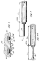
- FIG. 2 is a cross-sectional view of a z carrier spacer support system of CNC machine in FIG. 1.
- FIG. 2a is a perspective view of an adjustable spacer for z carrier spacer support in FIG. 2.
- FIG. 3 is a cross-sectional view of a y carrier spacer support system of CNC machine in FIG. 1.
- FIG. 4 is a sideways diagrammatic view of a TVG test bar mounted in a spindle mechanism of CNC machine in FIG. 1.
- FIG. 4a is a sideways diagrammatic view of a trigger type probe mounted in a spindle mechanism of CNC machine in FIG. 1.
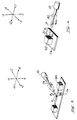
- FIG. 5 is a perspective diagrammatic view illustrating a procedure to determine the alignment on geometric condition of the spindle center of rotation using TVG test bar of FIG. 4 in accordance with one embodiment of the present invention.
- FIG. 6 is a perspective view generally illustrating the probing procedure of the present invention.
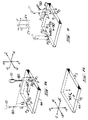
- FIG. 7a is a perspective diagrammatic view illustrating a procedure to evaluate the X home position of CNC machine in FIG. 1.
- FIG. 7b is a perspective diagrammatic view illustrating a procedure to evaluate the Z home position of CNC machine in FIG. 1.
- FIG. 8 is a perspective diagrammatic view illustrating a procedure for evaluating a tilt of a table B axis of a rotatable tabletop of CNC machine in FIG. 1.
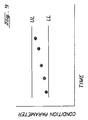
- FIG. 9 is a graph of illustrating a trend for a geometric condition of a machine component in FIG. 1.
- CNC machine 6 of the 5 axis multi-purpose milling, drilling, and boring machine type such as the T-30 manufactured by Cincinnati Milacron.
- CNC machine 6 is generally constructed about a column 8 mounted on a linearly movable machine base 12 slidably resting on horizontal X direction guideways 16 parallel to the X axis.
- CNC machine 6 functions to position, power, and control a spindle mechanism 10, rotatable about its centerline of rotation C, relative to a positionable work table 11.
- spindle mechanism 10 includes a tool holder 14 adapted for receiving and retaining various cutting tools, measuring devices, and probes used in the machining process.
- CNC machine 6 provides a means to move spindle mechanism 10, while it is spinning a tool mounted in its tool holder 14, relative to a work piece (not shown) mounted at a particular position on a work table 11. Relative positioning between work piece and spinning spindle mechanism 10 is provided along 3 linear motion axis X, Y, and Z and about two rotational axes, trunnion axis A and table axis B as shown in the corresponding reference axis in FIG. 1.
- CNC machine 6 has a spindle carrier 22 to which spindle mechanism 10 is trunnioned thereby allowing spindle mechanism 10 to be pivoted about trunnion axis A which is parallel to the X axis.
- Spindle carrier 22 is slidably mounted to vertical or Y guideways 30, which in turn are mounted to column 8, to provide motion along the Y axis for spindle mechanism 10.
- Horizontal Z direction guideways 36 slideably support work table 11 having a tabletop 44 rotatable about a vertical table axis B which, when properly assigned, is parallel to the Y axis.
- the present invention in its preferred embodiment is designed to be use without a work piece mounted on a movable pallet (not shown) which is removably mountable to tabletop 44 (which is also referred to as a clamp plate when adapted to secure a movable pallet).
- the evaluation procedures of the present invention are preferably carried out without the pallet and work piece mounted on machine 6 and are preferably done with the pallet in transit, such as on an automated guide vehicle (also not shown), in order to eliminate or significantly reduce the amount of time machine 6 is not running.
- the top of clamp plate 44 provides a reference top surface 56 which is rotatable about table axis B.
- Work table 11 includes a Z carrier 13 which is provided with a means for adjusting or aligning table axis B by adjusting four sets of z carrier spacers 60 (the location of three shown) upon which work table 11 rests.
- Another 4 sets of y carrier spacers 62 (the location of three shown), for use in mounting spindle carrier 22 to vertical guideways 30, are used to align trunnion axis A of spindle mechanism 10.
- FIG. 2 Illustrated in FIG. 2 is a conventional z carrier support spacer 60 supporting z carrier 13 on z guideways 36 and mounted to z roller bearing packs 58 having roller bearings 59.
- Two z side spacers 61 lie essentially along the same z coordinate on z carrier 13 and are also used for component alignment.
- Carrier support spacer 60 is more particularly illustrated In FIG. 2a as having a grind stock 63 with a height D for grinding in order to adjust the carrier, side spacers are similarly constructed with a grind stock.
- y carrier 22 is supported on guideways 30 by conventional y carrier support spacers 60' which are mounted on y roller bearing packs 58' having roller bearings 59.
- Two z side spacers 61' lie essentially along the same y coordinate on y carrier 22 and are also used for component alignment.
- an automatic tool changing mechanism 70 is provided for CNC machine 6, of a type commonly used in the industry, and is adapted to store a TVG test bar (tool verification gauge test bar 74 and trigger probes 80 as illustrated in FIGS. 4 and 4a respectively.
- FIG. 4 Illustrated in FIG. 4 is a TVG test bar 74 which is a standardized reference having a known diameter and fixed length L to its spindle gauge line SPGL at which point it mates, at a known trunnion length L2 measured from axis A to SPGL, to spindle mechanism 10.
- FIG. 4a illustrates a conventional trigger type probe 80 such as a Renishaw touch trigger probe, which is also stored in automatic tool changing mechanism 70, for use in making the alignment measurements. Probe 80 is also constructed to mate to spindle mechanism 10 at their common spindle gauge line SPGL.
- a beam actuated measuring device 84 is counted to a platform 11a (extending from Z carrier 13) which has been conventionally used for accurately measuring lengths of tools.
- a beam type device often referred to as a TVG beam (tool verification gauge beam)
- TVG beam tool verification gauge beam
- Another conventional reference device is a datum cube 90 shown fixedly mounted to a second platform 11b extending from worktable 11 and used in conjunction with probes to evaluate the geometric condition of spindle mechanism 10 with respect to its degrees of freedom of motion.
- Control of CNC machine is provided by a computerized controller 64 having a display 68 and generally mounted near or in the vicinity of column 8 and work table 11.
- Computerized controller 64 is capable of being programmed to machine a work piece and is programmable for making alignment measurements, calculating the amount of misalignment, and displaying the amount of misalignment on display 68. Programs are loaded in a conventional manner using CNC tapes.
- Misalignment of a machine component occurs when a geometric condition of the machine's component varies from preplanned, programmed, or restoration values. Though some linear misalignments can be compensated by incorporating offsets by well known techniques in the machining programs, angular misalignments, table axis B for example, conventionally require human measurements and adjustments to properly realign the respective components.
- controller 64 is programmed with a table or set of alignments instructions for an operator to follow to align a machine component such as work table 11 in order to restore table axis B to its parallel position to reference axis Y if so desired.
- the logic to evaluate the misalignment and determine whether restoration is desired is also programmed into controller 64 by CNC tape.
- the schedule of alignment procedures is stored as a function of machine component misalignment measurements which in the preferred embodiment are made by detecting the position in space of a feature on the machine component at two or more different position.
- FIG. 5 Illustrated in FIG. 5 is one embodiment of the present invention to evaluate the geometric condition of the angular degree of freedom of motion of the spindle's centerline of rotation C of spindle mechanism 10 in the ZY plane using TVG test bar 74.
- Spindle 10 is then extended a distance in the Z direction delta z and the procedure is repeated to determine a second set of coordinates Z2 and Y2 by passing the TVG bar through the TVG beam at a second position P2.
- TVG beam 85 is then probed by TVG bar 74 and breaks TVG beam 84 at a Y2 coordinate which should be equal to the Y1 coordinate otherwise the spindle's centerline of rotation C of spindle mechanism 10 is not properly aligned and may require alignment.
- FIG. 6 generally illustrates a probing technique using a trigger type probe to illustrate the present invention, a series of computerized machine instructions to machine 6, in FIG. 1, coded on a programmable computer readable media such as a CNC tape.
- a trigger probe 80 mounted in a spindle mechanism 10 is used to evaluate a position P1 of a contact point P related to a respective geometric condition and a degree of freedom of motion of that component.
- a probing path to probe first position P1 is indicated by dotted lines 11. This convention will be used in the discussion below.
- Probing, in three dimensional space is typically performed in a coordinate direction, such as in the X direction, to determine a corresponding coordinate, such as X0, of a position, such as P0.
- the other two coordinates, such as Y0 and Z0 are set by the numerical controller of the machine while a probe is used to the strike position, P0, and capture and record the third coordinate, X0.
- Evaluation of X and Z axis home positions in accordance with the preferred embodiment of the present invention is illustrated in FIGS. 7a and 7b respectively.
- Evaluation of home or 0 positions of the X an Z axes of machine 6 may be used for machine restoration and is also useful for calculation and storage in controller 64 of respective offsets used by the machine to accurately position spindle mechanism 10 and a rotary tool point of a tool that would be mounted therein during machining.
- Trigger probe 80 is used, its first position P1 is probed using a probe path illustrated in dotted line format, and its second position P2 is probed using a probe path illustrated in dashed line format.
- probe 80 mounted in spindle mechanism 10, at a trunnion angle a -90° and in line with table axis B, is brought in to touch tabletop 44 near its edge to determine it's height or Y position.
- the top surface of tabletop 44 is probed with probe 80 at a point having a position P0, near the edge of tabletop 44.
- probe 80 held at a position slightly below tabletop height, e.g. .25 inches below a contact point P on the tabletop 44 is probed in the +X direction.
- a first position P1 and its x coordinate X1 (having a -X value) is recorded by controller 64.
- probe 80 is withdrawn and moved in the +X direction to the other aide of tabletop 44, as indicated by the dashed line and arrows, tabletop 44 is rotated 180° about table axis B. Probe 80 is also rotated 180° about the centerline of rotation C of spindle mechanism 10, to eliminate any error due to a possibly bent probe, and tabletop 44 is probed in the -X direction at the same contact point P at a second position P2 having a new X coordinate X2 (having + X value) and the same Y and Z coordinates as P1. If the absolute values of both X1 and X2 are equal then the home position in controller 64 is correct. If the there is a difference then an X displacement (offset) is calculated as being half the difference between the X1 and X2 values.
- FIG. 7b illustrates a method by which the Z axis home position can be found using the apparatus and methodology of the present invention.
- a contact point P is probed from the -X and +X direction, at two positions that are 180° apart and are in line with and on either side of table axis B, and in the same manner as illustrated in FIG. 7a.
- a tabletop radius R from table axis B to position P1 is determined by dividing the difference of the X coordinates of positions P1 and P2 by 2, i.e. (X1-X2)/2).
- tabletop 44 and contact point P are rotated 90° about B axis from position P1 to position P3 and probe 80 is rotated 90 degrees to offset any bent probe effect.
- One embodiment of the present invention is a technique to automatically evaluate the tilt of table axis B of rotatable tabletop 44 as illustrated in FIG. 8.
- Table axis B may have a tilt in a XY plane and in a ZY plane.
- Probe 80 is used to probe a contact point P on top surface 56 of tabletop 44 at two positions 180° apart in a first plane and at a third position 90,° in between the first two, in a second plane orthogonal to the first plane, passing through table axis B.
- This first path of probe 80 is indicated by a dashed line and used to measure and record the coordinates of position P1 at the time of the probe strike at P1 as X1, Y1 and Z1.
- probe 80 is withdrawn and moved to the other side of tabletop 44 which is rotated 180°.
- Tabletop 44 is probed in the -X direction to establish P0' and an X run in.
- Contact point P in the -Y direction is then probed at a second position P2 on surface 56 of tabletop 44 in the same manner as for P1, as shown by the dotted line, to determine Y2 at X2 and Z1. Note the Z coordinate does not change.
- the tabletop is then rotated 90° from its first position to move contact point P to a third position P3.
- Contact point P is then probed in the same manner as in positions P1 and P2 to determine a Y3 at X3 and Z3.
- the X3 axis position is (X2 + X1)/2.
- the distance of the probe strike location from the B axis of rotation is (X2 - X1)/2.
- the probe strike location is then rotated 90 degrees and the Z1 axis position is moved a distance that the probe strike location is from the B axis of rotation (X2 - X1)/2 for the Z3 position.
- This procedure provides the data to calculate the tilt of table axis B in the ZY and YX planes. Tilt in the XY plane is equal to (Y2-Y1)/(X2-X1) and tilt in the ZY plane is equal to [Y3-(Y2+Y1)/2]/(Z3-Z1).
- the present invention contemplates the storage of certain cautions and other instructions which would be displayed at this point in the operation.
- An example of such a caution is as follows.
- Reset Z carrier preload to 120 inch pounds.
- Such evaluations and alignments may be run several times a year.
- a correction or alignment is carried out a confirming evaluation run should be made again which, because of the speed afforded by the present invention, enhances the reliability of the NC machine.
- Evaluations of an NC machine may not always require adjustments, corrections, or alignments and the present invention also provides for evaluations to be stored in controller 64 and passed on to a host digital numerical control (DNC) computer for statistical deterministic prediction maintenance techniques whereby a geometric condition of a machine component may be tracked between an upper limit UL and a lower limit LL as illustrated in the graph of FIG. 9. A trend may be shown between upper and lower limits so that maintenance may be performed before a machining error is made.
- DNC digital numerical control
- Appendix A is an NC code listing illustrating various embodiments of the present invention and is subject to copyright protection.
- the copyright owner has no objection to the facsimile reproduction by anyone of the patent document or the patent disclosure, as it appears In the Patent and Trademark Office patent file or records, but otherwise reserves all copyright rights whatsoever.
Abstract
Description
- The invention relates to computer numerically controlled machines and and in particular to automated machine component evaluation for use in aligning and maintaining such machines.
- Computer numerically controlled (CNC) machines are used to accurately machine and produce parts in an efficient and repeatable maner. CNC machines typically use compensation techniques to account for linear positional errors, and tool length errors. Methods and apparatuses are conventionally avalaible to manually evaluate a CNC machine's geometric conditions with respect to their various degrees of freedom of motion to determine whether alignment or machine restoration is required. Automatic tool length compensation is also available to evaluate machine rotary tool length and compensation lengths for use by CNC machines. These techniques are used for insuring machining accuracy.
- Various devices, probes, and systems have been developed for accurately and automatically measuring tool length errors and work piece dimensions. Examples of such systems, using sensor apparatuses commonly referred to as touch trigger probes, are illustrated in U.S. Patent No. 4,382,215 entitled "System and Method of Precision Machining", by Allan R. Barlow and William A. Hunter, which issued on May 3, 1983; U.S. Patent No. 4,428,055, entitled "Tool Touch Probe System and Method of Precision Machining", by John R. Zubrick and John R. Kelley, which issued on January 24, 1984; and U.S. Patent No. 4,899,094 entitled "Method of Calibration for an Automatic Machine Tool" by David I. Pilborough, which issued on February 6, 1990, and is assigned to Renishaw plc in England. These patents provide background information as well as illustrate some of the prior art.
- Good machine maintenance involving machine evaluation and restoration is important for accurate and precision machining. Conventional machine maintenance evaluation is labor intensive and dependant. Because of the amount of human intervention required differences occur in the machine's evaluation and restoration. Different technicians may perform the maintenance procedures slightly differently. Environmental differences such as temperature may also effect the alignment of machine components.
- Another problem associated with conventional restoration procedures relates to repeatability which is a particular concern for machining operations using statistical analysis to improve quality.
- Therefore, there exists a need to accurately evaluate a machine's geometric condition during the machining process without significantly interrupting the flow of work though the machine. There is also a need to evaluate and restore the machine in a quicker more repeatable manner than is conventionally available.
- The present invention provided a system and method for automatically, accurately, and repeatably evaluating a geometric condition of a computer numerically controlled (CNC) machine components with respect to its degrees of freedom of motion and issuing aligning instructions to the machine operator.
- The present invention provides a CNC machine having spindle mounted probes to measure relative positions of movable machine components, a computerized control means to direct spindle mounted probes to measure at least two different positions of a movable machine component, and a computing means that uses the measured positions to calculate the geometric condition of the machine component related to a degree of freedom of motion of the component.
- The preferred embodiment uses a computer to both control the CNC machine's operation including its spindle movement and perform the calculations associated with the present invention. A computing means is provided for calculating misalignment of the machine's movable component. Alignment means is provided for determining and issuing alignment instructions for the component. The preferred embodiment uses a CNC controller display to display the calculated amount of misalignment and issue alignment instructions.
- The invention is further set forth in
claims 1 and 6. - The foregoing aspects and other features of the invention are explained in the following description, taken in connection with the accompanying drawing where:
- FIG. 1 is a perspective view illustrating a CNC machine including a reference coordinate system in accordance with the preferred embodiment of the present invention.
- FIG. 2 is a cross-sectional view of a z carrier spacer support system of CNC machine in FIG. 1.
- FIG. 2a is a perspective view of an adjustable spacer for z carrier spacer support in FIG. 2.
- FIG. 3 is a cross-sectional view of a y carrier spacer support system of CNC machine in FIG. 1.
- FIG. 4 is a sideways diagrammatic view of a TVG test bar mounted in a spindle mechanism of CNC machine in FIG. 1.
- FIG. 4a is a sideways diagrammatic view of a trigger type probe mounted in a spindle mechanism of CNC machine in FIG. 1.
- FIG. 5 is a perspective diagrammatic view illustrating a procedure to determine the alignment on geometric condition of the spindle center of rotation using TVG test bar of FIG. 4 in accordance with one embodiment of the present invention.
- FIG. 6 is a perspective view generally illustrating the probing procedure of the present invention.
- FIG. 7a is a perspective diagrammatic view illustrating a procedure to evaluate the X home position of CNC machine in FIG. 1.
- FIG. 7b is a perspective diagrammatic view illustrating a procedure to evaluate the Z home position of CNC machine in FIG. 1.
- FIG. 8 is a perspective diagrammatic view illustrating a procedure for evaluating a tilt of a table B axis of a rotatable tabletop of CNC machine in FIG. 1.
- FIG. 9 is a graph of illustrating a trend for a geometric condition of a machine component in FIG. 1.
- Illustrated in FIG. 1 is a computer numerically controlled (CNC)
machine 6 of the 5 axis multi-purpose milling, drilling, and boring machine type such as the T-30 manufactured by Cincinnati Milacron.CNC machine 6 is generally constructed about acolumn 8 mounted on a linearlymovable machine base 12 slidably resting on horizontalX direction guideways 16 parallel to the X axis.CNC machine 6 functions to position, power, and control aspindle mechanism 10, rotatable about its centerline of rotation C, relative to a positionable work table 11. Powered by the machine's motor (not shown),spindle mechanism 10 includes atool holder 14 adapted for receiving and retaining various cutting tools, measuring devices, and probes used in the machining process. -
CNC machine 6 provides a means to movespindle mechanism 10, while it is spinning a tool mounted in itstool holder 14, relative to a work piece (not shown) mounted at a particular position on a work table 11. Relative positioning between work piece andspinning spindle mechanism 10 is provided along 3 linear motion axis X, Y, and Z and about two rotational axes, trunnion axis A and table axis B as shown in the corresponding reference axis in FIG. 1. -
CNC machine 6 has aspindle carrier 22 to whichspindle mechanism 10 is trunnioned thereby allowingspindle mechanism 10 to be pivoted about trunnion axis A which is parallel to the X axis. The centerline of rotation C, ofspindle mechanism 10, is parallel to the Z axis when trunnion angle a=0°.Spindle carrier 22 is slidably mounted to vertical orY guideways 30, which in turn are mounted tocolumn 8, to provide motion along the Y axis forspindle mechanism 10. - Horizontal
Z direction guideways 36 slideably support work table 11 having atabletop 44 rotatable about a vertical table axis B which, when properly assigned, is parallel to the Y axis. The present invention in its preferred embodiment is designed to be use without a work piece mounted on a movable pallet (not shown) which is removably mountable to tabletop 44 (which is also referred to as a clamp plate when adapted to secure a movable pallet). The evaluation procedures of the present invention are preferably carried out without the pallet and work piece mounted onmachine 6 and are preferably done with the pallet in transit, such as on an automated guide vehicle (also not shown), in order to eliminate or significantly reduce the amount oftime machine 6 is not running. The top ofclamp plate 44 provides areference top surface 56 which is rotatable about table axis B. - Work table 11 includes a
Z carrier 13 which is provided with a means for adjusting or aligning table axis B by adjusting four sets of z carrier spacers 60 (the location of three shown) upon which work table 11 rests. Another 4 sets of y carrier spacers 62 (the location of three shown), for use in mountingspindle carrier 22 tovertical guideways 30, are used to align trunnion axis A ofspindle mechanism 10. - Illustrated in FIG. 2 is a conventional z
carrier support spacer 60 supportingz carrier 13 onz guideways 36 and mounted to zroller bearing packs 58 havingroller bearings 59. Two z side spacers 61 (one of which is shown) lie essentially along the same z coordinate onz carrier 13 and are also used for component alignment.Carrier support spacer 60 is more particularly illustrated In FIG. 2a as having agrind stock 63 with a height D for grinding in order to adjust the carrier, side spacers are similarly constructed with a grind stock. Similar to z carrier spacer arrangement in FIG. 2 is y carrier spacer arrangement illustrated in FIG. 3 wherebyy carrier 22 is supported onguideways 30 by conventional y carrier support spacers 60' which are mounted on y roller bearing packs 58' havingroller bearings 59. Two z side spacers 61' (only one shown) lie essentially along the same y coordinate ony carrier 22 and are also used for component alignment. - Referring back briefly to FIG. 1, an automatic
tool changing mechanism 70 is provided forCNC machine 6, of a type commonly used in the industry, and is adapted to store a TVG test bar (tool verificationgauge test bar 74 and trigger probes 80 as illustrated in FIGS. 4 and 4a respectively. - Illustrated in FIG. 4 is a
TVG test bar 74 which is a standardized reference having a known diameter and fixed length L to its spindle gauge line SPGL at which point it mates, at a known trunnion length L2 measured from axis A to SPGL, tospindle mechanism 10. FIG. 4a illustrates a conventionaltrigger type probe 80 such as a Renishaw touch trigger probe, which is also stored in automatictool changing mechanism 70, for use in making the alignment measurements.Probe 80 is also constructed to mate tospindle mechanism 10 at their common spindle gauge line SPGL. - Referring again to FIG. 1, a beam actuated measuring
device 84 is counted to a platform 11a (extending from Z carrier 13) which has been conventionally used for accurately measuring lengths of tools. Such a beam type device, often referred to as a TVG beam (tool verification gauge beam), is explained in more detail in U.S. Patent No. 4,518,257 entitled "Optical Inspection System and Method", by Charles Wayne Donaldson, which issued on May 21, 1985, is incorporated herein by reference. Another conventional reference device is a datum cube 90 shown fixedly mounted to a second platform 11b extending from worktable 11 and used in conjunction with probes to evaluate the geometric condition ofspindle mechanism 10 with respect to its degrees of freedom of motion. - Control of CNC machine is provided by a computerized controller 64 having a
display 68 and generally mounted near or in the vicinity ofcolumn 8 and work table 11. Computerized controller 64 is capable of being programmed to machine a work piece and is programmable for making alignment measurements, calculating the amount of misalignment, and displaying the amount of misalignment ondisplay 68. Programs are loaded in a conventional manner using CNC tapes. - Misalignment of a machine component occurs when a geometric condition of the machine's component varies from preplanned, programmed, or restoration values. Though some linear misalignments can be compensated by incorporating offsets by well known techniques in the machining programs, angular misalignments, table axis B for example, conventionally require human measurements and adjustments to properly realign the respective components.
- Another feature of the preferred embodiment of the present invention is that controller 64 is programmed with a table or set of alignments instructions for an operator to follow to align a machine component such as work table 11 in order to restore table axis B to its parallel position to reference axis Y if so desired. The logic to evaluate the misalignment and determine whether restoration is desired is also programmed into controller 64 by CNC tape. The schedule of alignment procedures is stored as a function of machine component misalignment measurements which in the preferred embodiment are made by detecting the position in space of a feature on the machine component at two or more different position.
- Several types of machine component evaluations are contemplated by the present invention. Some of these are illustrated herein. Though the illustrations herein are shown for a Cincinnati Milacron T-30 5 axes machine it should be understood that the Invention is applicable to any NC machine with similar machine components.
- Illustrated in FIG. 5 is one embodiment of the present invention to evaluate the geometric condition of the angular degree of freedom of motion of the spindle's centerline of rotation C of
spindle mechanism 10 in the ZY plane usingTVG test bar 74.Spindle mechanism 10, in the horizontal position at an angle a=0°, is moved downward to break aninfrared TVG beam 85 of beam actuated measuringdevice 84 at which point controller 64 then records a first position P1 having a z coordinate Z1 and a y coordinate Y1.Spindle 10 is then extended a distance in the Z direction delta z and the procedure is repeated to determine a second set of coordinates Z2 and Y2 by passing the TVG bar through the TVG beam at a second position P2.TVG beam 85 is then probed byTVG bar 74 and breaksTVG beam 84 at a Y2 coordinate which should be equal to the Y1 coordinate otherwise the spindle's centerline of rotation C ofspindle mechanism 10 is not properly aligned and may require alignment. - FIG. 6 generally illustrates a probing technique using a trigger type probe to illustrate the present invention, a series of computerized machine instructions to
machine 6, in FIG. 1, coded on a programmable computer readable media such as a CNC tape. Atrigger probe 80 mounted in aspindle mechanism 10 is used to evaluate a position P1 of a contact point P related to a respective geometric condition and a degree of freedom of motion of that component. A probing path to probe first position P1 is indicated by dotted lines 11. This convention will be used in the discussion below. Probing, in three dimensional space, is typically performed in a coordinate direction, such as in the X direction, to determine a corresponding coordinate, such as X0, of a position, such as P0. The other two coordinates, such as Y0 and Z0, are set by the numerical controller of the machine while a probe is used to the strike position, P0, and capture and record the third coordinate, X0. - Evaluation of X and Z axis home positions in accordance with the preferred embodiment of the present invention is illustrated in FIGS. 7a and 7b respectively. Evaluation of home or 0 positions of the X an Z axes of
machine 6 may be used for machine restoration and is also useful for calculation and storage in controller 64 of respective offsets used by the machine to accurately positionspindle mechanism 10 and a rotary tool point of a tool that would be mounted therein during machining.Trigger probe 80 is used, its first position P1 is probed using a probe path illustrated in dotted line format, and its second position P2 is probed using a probe path illustrated in dashed line format. - Referring to FIG. 7a for the X axis home position evaluation,
probe 80 mounted inspindle mechanism 10, at a trunnion angle a=-90° and in line with table axis B, is brought in to touchtabletop 44 near its edge to determine it's height or Y position. The top surface oftabletop 44 is probed withprobe 80 at a point having a position P0, near the edge oftabletop 44. Then withprobe 80 held at a position slightly below tabletop height, e.g. .25 inches below, a contact point P on thetabletop 44 is probed in the +X direction. A first position P1 and its x coordinate X1 (having a -X value) is recorded by controller 64. Next,probe 80 is withdrawn and moved in the +X direction to the other aide oftabletop 44, as indicated by the dashed line and arrows,tabletop 44 is rotated 180° about tableaxis B. Probe 80 is also rotated 180° about the centerline of rotation C ofspindle mechanism 10, to eliminate any error due to a possibly bent probe, andtabletop 44 is probed in the -X direction at the same contact point P at a second position P2 having a new X coordinate X2 (having + X value) and the same Y and Z coordinates as P1. If the absolute values of both X1 and X2 are equal then the home position in controller 64 is correct. If the there is a difference then an X displacement (offset) is calculated as being half the difference between the X1 and X2 values. - FIG. 7b illustrates a method by which the Z axis home position can be found using the apparatus and methodology of the present invention. First a contact point P is probed from the -X and +X direction, at two positions that are 180° apart and are in line with and on either side of table axis B, and in the same manner as illustrated in FIG. 7a. Having thus set the X home position by probing positions P1 and P2 as in FIG. 7a, a tabletop radius R from table axis B to position P1 is determined by dividing the difference of the X coordinates of positions P1 and P2 by 2, i.e. (X1-X2)/2). Then
tabletop 44 and contact point P are rotated 90° about B axis from position P1 to position P3 and probe 80 is rotated 90 degrees to offset any bent probe effect. Then, withprobe 80 mounted inspindle mechanism 10 at a trunnion angle a=-90°, contact point P ontabletop 44 is probed in the -Z direction at position P3 and should have a position a distance R from table axis B. - One embodiment of the present invention is a technique to automatically evaluate the tilt of table axis B of
rotatable tabletop 44 as illustrated in FIG. 8. Table axis B may have a tilt in a XY plane and in a ZY plane.Probe 80 is used to probe a contact point P ontop surface 56 oftabletop 44 at two positions 180° apart in a first plane and at a third position 90,° in between the first two, in a second plane orthogonal to the first plane, passing through table axis B. - First,
tabletop 44, with table axis B set at b=0°, is probed at point P0 on its -X facing edge withprobe 80 mounted inspindle mechanism 10 at a trunnion angle a=0, and its X coordinate, X0, is recorded.Probe 80 then probes, in the -Y direction, a contact point P onsurface 56 having a first position P1 which is at trunnion angle a=0 and at an X coordinate slightly inward from -X facing side oftabletop 44 having an X run in of about .25 inches (i.e. X1 = X0 - .25"). This first path ofprobe 80 is indicated by a dashed line and used to measure and record the coordinates of position P1 at the time of the probe strike at P1 as X1, Y1 and Z1. - Next,
probe 80 is withdrawn and moved to the other side oftabletop 44 which is rotated 180°.Tabletop 44 is probed in the -X direction to establish P0' and an X run in. Contact point P in the -Y direction is then probed at a second position P2 onsurface 56 oftabletop 44 in the same manner as for P1, as shown by the dotted line, to determine Y2 at X2 and Z1. Note the Z coordinate does not change. The tabletop is then rotated 90° from its first position to move contact point P to a third position P3. Contact point P is then probed in the same manner as in positions P1 and P2 to determine a Y3 at X3 and Z3. The X3 axis position is (X2 + X1)/2. The distance of the probe strike location from the B axis of rotation is (X2 - X1)/2. The probe strike location is then rotated 90 degrees and the Z1 axis position is moved a distance that the probe strike location is from the B axis of rotation (X2 - X1)/2 for the Z3 position. This procedure provides the data to calculate the tilt of table axis B in the ZY and YX planes. Tilt in the XY plane is equal to (Y2-Y1)/(X2-X1) and tilt in the ZY plane is equal to [Y3-(Y2+Y1)/2]/(Z3-Z1). - Measurements are typically made in inches and tilt evaluations are conventionally displayed in taper per foot which is inches per foot. Therefore, [(Y2-Y1)/(X2-X1)]*12 is the taper per foot in the X direction and [(Y3-(Y2+Y1)/2)/(Z3 - Z1)]*12 is the taper per foot in the Z direction, both of which are displayed on
display 68 in FIG. 1. The present invention provides controller 64 with a computer program whereby based on the misalignment of table axis B of work table 44 a set of alignment instructions may be displayed ondisplay 68. Alignment for table axis B is typically accomplished by adjusting z carrier spacers 60 as discussed above. By way of example, if B axis is off in both planes then 3 of the four z carrier spacers would have to be ground according to equations stored in controller 64. The screen would display instructions such as the following example.
.0014" off Z axis carrier spacer #1
.0008" off Z axis carrier spacer #3
.0022" off Z axis carrier spacer #4 - In addition the present invention contemplates the storage of certain cautions and other instructions which would be displayed at this point in the operation. An example of such a caution is as follows.
- Be sure clamp plate is clean of nicks and dirt.
- Reset Z carrier preload to 120 inch pounds.
- Rerun for correction needed.
- Such evaluations and alignments may be run several times a year. When a correction or alignment is carried out a confirming evaluation run should be made again which, because of the speed afforded by the present invention, enhances the reliability of the NC machine.
- Evaluations of an NC machine may not always require adjustments, corrections, or alignments and the present invention also provides for evaluations to be stored in controller 64 and passed on to a host digital numerical control (DNC) computer for statistical deterministic prediction maintenance techniques whereby a geometric condition of a machine component may be tracked between an upper limit UL and a lower limit LL as illustrated in the graph of FIG. 9. A trend may be shown between upper and lower limits so that maintenance may be performed before a machining error is made.
- Further illustrations may be found in Appendix A of this application. Appendix A is an NC code listing illustrating various embodiments of the present invention and is subject to copyright protection. The copyright owner has no objection to the facsimile reproduction by anyone of the patent document or the patent disclosure, as it appears In the Patent and Trademark Office patent file or records, but otherwise reserves all copyright rights whatsoever.
- While the embodiments of the present invention presented herein have been described fully in order to explain its principles, it is understood that various modifications or alterations may be made to the described embodiments without departing from the scope of the invention as set forth in the appended claims.


Claims (8)
- An alignment system for a computer numerically controlled (CNC) machine having movable machine components, said alignment system comprising:
a spindle having a spindle mounted tool holding means,
a probe means to measure relative positions of the machine components said sensor means mountable in said tool holding means,
a control means for using spindle mounted probe means to probe at least two different positions of a movable machine component,
a computing means for using at least two said measured positions to evaluate a geometric condition of the machine component with respect to said degree of freedom of motion of said machine component. - An alignment system as claimed in claim 1 wherein said computing means further comprises a means for calculating an amount of misalignment of said machine component with respect to said degree of freedom of motion of said machine component.
- An alignment system as claimed in claim 1 wherein said computing means further comprises:
a means for storing a schedule of alignment instructions as a function of a parameter related to said machine component degree of freedom of motion for aligning said machine component,
a means for comparing said calculated degree of motion against said schedule. - An alignment system as claimed in claim 2 wherein said computing means further comprises:
a means for storing a schedule of alignment instructions as a function of a misalignment parameter associated with said calculated amount of misalignment for aligning said machine component,
a means for comparing said calculated amount of misalignment against said schedule. - An alignment system as claimed in claim 4 further including a display screen associated with the control of the CNC machine and means for displaying said alignment instructions.
- A program having machine readable instructions for a computer numerically controlled (CNC) machine having movable machine components, said program comprising:
a means for directing spindle mounted probes to evaluate at least two different positions of a movable machine component relative to a degree of freedom of motion of the machine component,
a computing means for using at least said two measured positions to calculate a geometric condition of the machine component relative to said degree of freedom of motion of the machine component. - A program as claimed in claim 6 further comprising a means for calculating an amount of misalignment of the machine component from said geometric condition of the machine component with respect to said degree of freedom of motion of the machine component.
- A program as claimed in claim 7 further comprising a means for storing a schedule of alignment instructions as a function of a parameter related to said machine component degree of freedom of motion, said alignment instructions effective for aligning the machine component, a means for comparing said calculated geometric condition of said geometric condition of the machine component against said schedule, means for issuing alignment instructions for said geometric condition of the machine component.
Applications Claiming Priority (4)
| Application Number | Priority Date | Filing Date | Title |
|---|---|---|---|
| US800948 | 1985-11-22 | ||
| US80094891A | 1991-12-02 | 1991-12-02 | |
| US92006992A | 1992-07-27 | 1992-07-27 | |
| US920069 | 1992-07-27 |
Publications (3)
| Publication Number | Publication Date |
|---|---|
| EP0545658A2 true EP0545658A2 (en) | 1993-06-09 |
| EP0545658A3 EP0545658A3 (en) | 1993-07-14 |
| EP0545658B1 EP0545658B1 (en) | 1998-05-27 |
Family
ID=27122275
Family Applications (1)
| Application Number | Title | Priority Date | Filing Date |
|---|---|---|---|
| EP92310923A Expired - Lifetime EP0545658B1 (en) | 1991-12-02 | 1992-11-30 | Automated maintenance system for computer numerically controlled machines |
Country Status (5)
| Country | Link |
|---|---|
| US (1) | US5357450A (en) |
| EP (1) | EP0545658B1 (en) |
| JP (1) | JP2809948B2 (en) |
| CA (1) | CA2082790A1 (en) |
| DE (1) | DE69225680T2 (en) |
Cited By (10)
| Publication number | Priority date | Publication date | Assignee | Title |
|---|---|---|---|---|
| EP0729005A1 (en) * | 1995-02-23 | 1996-08-28 | Institut Für Fertigungstechnik Der Tu Graz | Measuring device with 6 degrees of freedom |
| WO1996027778A1 (en) * | 1995-03-03 | 1996-09-12 | Honeywell Inc. | Apparatus and method to provide high accuracy calibration of machine tools |
| EP1139189A2 (en) | 2000-03-29 | 2001-10-04 | The Boeing Company | Process for qualifying accuracy of a NC system |
| EP1914612A2 (en) * | 2006-10-14 | 2008-04-23 | Dr. Johannes Heidenhain GmbH | Method for positioning axes in machine tools |
| CN102189420A (en) * | 2010-03-12 | 2011-09-21 | 西门子公司 | Lathe and method for measuring workpiece clamping position in workpiece clamping device in lathe |
| CN107081641A (en) * | 2017-05-17 | 2017-08-22 | 中国工程物理研究院机械制造工艺研究所 | A kind of flexible cutter automatic tool setting device and method |
| EP2474388A3 (en) * | 2011-01-11 | 2017-09-06 | JTEKT Corporation | Workpiece centering apparatus and workpiece centering method |
| CN108469782A (en) * | 2018-02-08 | 2018-08-31 | 西南交通大学 | A kind of installation error discrimination method based on rotary shaft composition error measured value |
| EP3473379A1 (en) * | 2017-10-20 | 2019-04-24 | ISOG Technology GmbH | Grinding center and method for axis compensation of a grinding center |
| CN111854587A (en) * | 2020-07-21 | 2020-10-30 | 大连理工大学 | Guide rail five-degree-of-freedom motion error online measurement device and method |
Families Citing this family (29)
| Publication number | Priority date | Publication date | Assignee | Title |
|---|---|---|---|---|
| US5796619A (en) * | 1996-02-15 | 1998-08-18 | The Boeing Company | Method and apparatus for numerically controlled probing |
| US6022132A (en) * | 1996-11-15 | 2000-02-08 | Thermwood Corporation | Method and apparatus for programming a CNC machine with a probe |
| JP3071758B2 (en) * | 1998-05-20 | 2000-07-31 | ヤマザキマザック株式会社 | Three-dimensional laser beam machine and processing control method for processing program in three-dimensional laser beam machine |
| US6427098B1 (en) | 1999-03-22 | 2002-07-30 | Unova Ip Corp | Method for controlling pivoting machine member |
| US6225771B1 (en) | 1999-12-01 | 2001-05-01 | General Electric Company | Probe chord error compensation |
| US6810600B1 (en) | 2000-02-02 | 2004-11-02 | Unova Ip Corp. | Apparatus and method for monitoring alignment of a CNC machine spindle trunnion axis A |
| JP3566166B2 (en) * | 2000-02-10 | 2004-09-15 | 株式会社新川 | Tool position measuring method, offset measuring method, reference member and bonding device |
| US6453211B1 (en) * | 2000-03-02 | 2002-09-17 | General Electric Company | Nominal shift machining |
| US6895298B2 (en) * | 2003-01-17 | 2005-05-17 | The Boeing Company | Multi-axis cutter diameter compensation for numeric control machine tools |
| US7140119B2 (en) * | 2004-04-23 | 2006-11-28 | Corning Incorporated | Measurement of form of spherical and near-spherical optical surfaces |
| KR100586831B1 (en) * | 2004-05-11 | 2006-06-08 | 고등기술연구원연구조합 | On-the-machine measurement device for super-precision turning operations using a accelerometer |
| US7090561B2 (en) * | 2004-12-07 | 2006-08-15 | General Electric Company | Method and apparatus for pivot point determination and machine tool adjustment |
| DE102005015063B4 (en) * | 2005-03-31 | 2008-05-15 | Schott Ag | Apparatus and method for the automatic generation of control instructions for rotary machines |
| US7784183B2 (en) * | 2005-06-09 | 2010-08-31 | General Electric Company | System and method for adjusting performance of manufacturing operations or steps |
| GB0525306D0 (en) | 2005-12-13 | 2006-01-18 | Renishaw Plc | Method of machine tool calibration |
| ATE504868T1 (en) * | 2006-05-31 | 2011-04-15 | Panasonic Corp | METHOD FOR CALCULATION OF A CENTER OF ROTATION, METHOD FOR CALCULATION OF AN AXIS OF ROTATION, METHOD FOR CREATING A PROGRAM, OPERATING METHOD AND ROBOTIC DEVICE |
| SE530573C2 (en) * | 2006-11-16 | 2008-07-08 | Hexagon Metrology Ab | Method and apparatus for compensating geometric errors in processing machines |
| JP4291382B2 (en) | 2007-07-31 | 2009-07-08 | ファナック株式会社 | Machine tool with automatic correction function of mounting error by contact detection |
| WO2009057229A1 (en) | 2007-11-02 | 2009-05-07 | Makino Milling Machine Co., Ltd. | Method and device for preparing error map and numerically controlled machine tool having error map preparation function |
| US7690130B1 (en) | 2008-05-30 | 2010-04-06 | Elizabeth Carbide Kentucky, Inc. | Punch deflection gauge |
| CN101887250B (en) * | 2009-05-12 | 2012-05-30 | 鸿富锦精密工业(深圳)有限公司 | CNC (Computerized Numerical Control) machine tool control device |
| US8761920B2 (en) * | 2011-03-16 | 2014-06-24 | GM Global Technology Operations LLC | Automatic probing, compensation, and adjustment of a flexible fixture for a CNC machine |
| US9784554B2 (en) | 2012-03-20 | 2017-10-10 | Hurco Companies, Inc. | Method for measuring a rotary axis of a machine tool system |
| DE102013018654A1 (en) * | 2013-10-30 | 2015-04-30 | Jenoptik Automatisierungstechnik Gmbh | Method and device for detecting and correcting a spatial position of a workpiece held in a positioning device |
| KR101640829B1 (en) * | 2014-05-19 | 2016-07-19 | (주)청호산업 | Apparatus For Processing Of Hydraulic Cylinder Gland |
| US20150338839A1 (en) * | 2014-05-20 | 2015-11-26 | Caterpillar Inc. | System to verify machining setup |
| DE102017005488A1 (en) * | 2017-06-09 | 2018-12-13 | Blum-Novotest Gmbh | Apparatus and method for measuring and controlling a rotary drivable tool in a machine tool |
| CN111381556A (en) * | 2018-12-29 | 2020-07-07 | 鸿富锦精密电子(成都)有限公司 | Processing equipment error correction method and system |
| CN110900305B (en) * | 2019-12-06 | 2021-04-20 | 襄阳华中科技大学先进制造工程研究院 | Method for measuring positioning error of machine tool workbench |
Citations (5)
| Publication number | Priority date | Publication date | Assignee | Title |
|---|---|---|---|---|
| FR2486264A1 (en) * | 1980-07-07 | 1982-01-08 | Berthiez | Localisation system for tool position on machine tool - uses probe at reference location to produce electrical position signal for control processor |
| DE3132921A1 (en) * | 1981-04-02 | 1982-10-28 | Heyligenstaedt & Co, Werkzeugmaschinenfabrik Gmbh, 6300 Giessen | Method of determining the wear of the tool in an NC machine tool, in particular an NC lathe |
| WO1988002139A1 (en) * | 1986-09-16 | 1988-03-24 | Renishaw Plc | A method of calibration for an automatic machine tool |
| EP0365958A2 (en) * | 1988-10-25 | 1990-05-02 | Mtu Motoren- Und Turbinen-Union MàNchen Gmbh | Method for the compensation of a thermally-caused zero point shift at processing machines, especially lathes, and device for carrying out the method |
| WO1991016673A1 (en) * | 1990-04-20 | 1991-10-31 | The Gleason Works | Multi-functional measurement system |
Family Cites Families (34)
| Publication number | Priority date | Publication date | Assignee | Title |
|---|---|---|---|---|
| US3963364A (en) * | 1963-01-11 | 1976-06-15 | Lemelson Jerome H | Tool control system and method |
| US3555254A (en) * | 1967-04-17 | 1971-01-12 | Gerber Scientific Instr Co | Error correcting system and method for use with plotters, machine tools and the like |
| US3953918A (en) * | 1975-06-25 | 1976-05-04 | Cincinnati Milacron, Inc. | Machine tool with automatic tool changer |
| US4135238A (en) * | 1976-01-26 | 1979-01-16 | Hamill Company, Inc. | Numerically controlled machine tool system |
| FR2389099A1 (en) * | 1977-04-25 | 1978-11-24 | Sopelem | OPTICAL DIMENSIONAL CONTROL PROCESS |
| JPS5816983B2 (en) * | 1977-08-26 | 1983-04-04 | 豊田工機株式会社 | Automatic centering device |
| JPS6022721B2 (en) * | 1978-07-06 | 1985-06-04 | 豊田工機株式会社 | Centering measurement device using contact detection head |
| DE2847510A1 (en) * | 1978-11-02 | 1980-06-04 | Hueller Hille Gmbh | METHOD FOR CORRECTING THE LENGTHS AND RADIUS OF TOOLS, ESPECIALLY FOR NUMERICALLY CONTROLLED MACHINES WITH POSITION OR TRAVEL MEASURING SYSTEMS BY MEANS OF THE REQUIRED-ACTUAL COMPARISON |
| US4370721A (en) * | 1980-09-02 | 1983-01-25 | Cincinnati Milacron Inc. | Method for modifying programmed positions by using a programmably controlled surface sensing element |
| US4403281A (en) * | 1981-04-03 | 1983-09-06 | Cincinnati Milacron Industries, Inc. | Apparatus for dynamically controlling the tool centerpoint of a robot arm off a predetermined path |
| US4382215A (en) * | 1981-07-16 | 1983-05-03 | General Electric Company | System and method of precision machining |
| US4428055A (en) * | 1981-08-18 | 1984-01-24 | General Electric Company | Tool touch probe system and method of precision machining |
| JPS58206364A (en) * | 1982-05-24 | 1983-12-01 | Toshiba Mach Co Ltd | Machine tool |
| US4518257A (en) * | 1982-07-28 | 1985-05-21 | General Electric Company | Optical inspection system and method |
| US4636960A (en) * | 1982-09-16 | 1987-01-13 | Renishaw Electrical Limited | Method of operating a machine tool with a sensing probe in order to gather positional data for the calculation of tool offset parameters |
| US4542467A (en) * | 1982-09-16 | 1985-09-17 | Renishaw Electrical Limited | Method of operating a machine tool with a sensing probe in order to gather positional data for the calculation of tool offset parameters |
| JPS60177848A (en) * | 1984-02-23 | 1985-09-11 | Mori Seiki Seisakusho:Kk | Correction of original point in nc machine tool |
| US4554495A (en) * | 1984-08-29 | 1985-11-19 | Ormand R. Austin | Datum reference for tool touch probe system |
| JPS61145611A (en) * | 1984-12-19 | 1986-07-03 | Fujitsu Ltd | Mounting method of electronic component |
| GB8624191D0 (en) * | 1986-10-08 | 1986-11-12 | Renishaw Plc | Datuming of analogue measurement probes |
| EP0289836B1 (en) * | 1987-05-04 | 1991-11-06 | Siemens Aktiengesellschaft | Method for positioning a tool of a multi-joint robot |
| JPS645753A (en) * | 1987-06-26 | 1989-01-10 | Toshiba Machine Co Ltd | Compensation of misalignment of work in machine tool under numerical control |
| US4887221A (en) * | 1987-09-25 | 1989-12-12 | Sunnen Products Company | Computer controlled honing machine using look up table data for automatic programming |
| US4866643A (en) * | 1987-10-09 | 1989-09-12 | Brown & Sharpe Manufacturing Company | Method for automatic compensation of probe offset in a coordinate measuring machine |
| US4939678A (en) * | 1987-11-19 | 1990-07-03 | Brown & Sharpe Manufacturing Company | Method for calibration of coordinate measuring machine |
| JPH0642164B2 (en) * | 1987-12-17 | 1994-06-01 | 新明和工業株式会社 | Control method for industrial robot |
| JP2508196B2 (en) * | 1988-06-30 | 1996-06-19 | ブラザー工業株式会社 | Processing machine |
| US4974165A (en) * | 1988-11-28 | 1990-11-27 | Mechanical Technology Incorporated | Real time machining control system including in-process part measuring and inspection |
| US5010491A (en) * | 1988-12-27 | 1991-04-23 | International Business Machines Corp. | Automated system for machining parts to close tolerances |
| US5036479A (en) * | 1989-04-20 | 1991-07-30 | Trw Inc. | Modular automated avionics test system |
| US5224052A (en) * | 1989-10-26 | 1993-06-29 | Hamar M R | Laser alignment control system |
| US5046032A (en) * | 1989-12-01 | 1991-09-03 | Bear Automotive Service Equipment Company | Calibration bar |
| US5208763A (en) * | 1990-09-14 | 1993-05-04 | New York University | Method and apparatus for determining position and orientation of mechanical objects |
| US5138799A (en) * | 1991-04-12 | 1992-08-18 | Bryant Grinder Corporation | Probe positioning mechanism for a radius dresser |
-
1992
- 1992-11-12 CA CA002082790A patent/CA2082790A1/en not_active Abandoned
- 1992-11-30 DE DE69225680T patent/DE69225680T2/en not_active Expired - Fee Related
- 1992-11-30 EP EP92310923A patent/EP0545658B1/en not_active Expired - Lifetime
- 1992-12-01 JP JP4321775A patent/JP2809948B2/en not_active Expired - Fee Related
-
1994
- 1994-02-10 US US08/189,862 patent/US5357450A/en not_active Expired - Lifetime
Patent Citations (5)
| Publication number | Priority date | Publication date | Assignee | Title |
|---|---|---|---|---|
| FR2486264A1 (en) * | 1980-07-07 | 1982-01-08 | Berthiez | Localisation system for tool position on machine tool - uses probe at reference location to produce electrical position signal for control processor |
| DE3132921A1 (en) * | 1981-04-02 | 1982-10-28 | Heyligenstaedt & Co, Werkzeugmaschinenfabrik Gmbh, 6300 Giessen | Method of determining the wear of the tool in an NC machine tool, in particular an NC lathe |
| WO1988002139A1 (en) * | 1986-09-16 | 1988-03-24 | Renishaw Plc | A method of calibration for an automatic machine tool |
| EP0365958A2 (en) * | 1988-10-25 | 1990-05-02 | Mtu Motoren- Und Turbinen-Union MàNchen Gmbh | Method for the compensation of a thermally-caused zero point shift at processing machines, especially lathes, and device for carrying out the method |
| WO1991016673A1 (en) * | 1990-04-20 | 1991-10-31 | The Gleason Works | Multi-functional measurement system |
Non-Patent Citations (1)
| Title |
|---|
| ZEITSCHRIFT FÜR INDUSTRIELLE FERTIGUNG vol. 74, no. 9, 1984, DE pages 539 - 544 H. HAHN * |
Cited By (17)
| Publication number | Priority date | Publication date | Assignee | Title |
|---|---|---|---|---|
| EP0729005A1 (en) * | 1995-02-23 | 1996-08-28 | Institut Für Fertigungstechnik Der Tu Graz | Measuring device with 6 degrees of freedom |
| US5767380A (en) * | 1995-02-23 | 1998-06-16 | Insitut Fur Fertigungstechnik, Technische Universitat Graz | Measuring arrangement and method for checking the geometric and dynamic accuracy of two machine elements displaceable with respect to one another |
| WO1996027778A1 (en) * | 1995-03-03 | 1996-09-12 | Honeywell Inc. | Apparatus and method to provide high accuracy calibration of machine tools |
| US5834623A (en) * | 1995-03-03 | 1998-11-10 | Ignagni; Mario B. | Apparatus and method to provide high accuracy calibration of machine tools |
| EP1139189A2 (en) | 2000-03-29 | 2001-10-04 | The Boeing Company | Process for qualifying accuracy of a NC system |
| EP1139189A3 (en) * | 2000-03-29 | 2006-11-22 | The Boeing Company | Process for qualifying accuracy of a NC system |
| EP1914612A2 (en) * | 2006-10-14 | 2008-04-23 | Dr. Johannes Heidenhain GmbH | Method for positioning axes in machine tools |
| EP1914612A3 (en) * | 2006-10-14 | 2010-01-13 | Dr. Johannes Heidenhain GmbH | Method for positioning axes in machine tools |
| CN102189420A (en) * | 2010-03-12 | 2011-09-21 | 西门子公司 | Lathe and method for measuring workpiece clamping position in workpiece clamping device in lathe |
| EP2474388A3 (en) * | 2011-01-11 | 2017-09-06 | JTEKT Corporation | Workpiece centering apparatus and workpiece centering method |
| CN107081641A (en) * | 2017-05-17 | 2017-08-22 | 中国工程物理研究院机械制造工艺研究所 | A kind of flexible cutter automatic tool setting device and method |
| CN107081641B (en) * | 2017-05-17 | 2019-04-26 | 中国工程物理研究院机械制造工艺研究所 | A kind of flexibility cutter automatic tool setting device and method |
| EP3473379A1 (en) * | 2017-10-20 | 2019-04-24 | ISOG Technology GmbH | Grinding center and method for axis compensation of a grinding center |
| WO2019077071A1 (en) * | 2017-10-20 | 2019-04-25 | ISOG Technology GmbH | Grinding center and method for axis compensation of a grinding center |
| CN108469782A (en) * | 2018-02-08 | 2018-08-31 | 西南交通大学 | A kind of installation error discrimination method based on rotary shaft composition error measured value |
| CN111854587A (en) * | 2020-07-21 | 2020-10-30 | 大连理工大学 | Guide rail five-degree-of-freedom motion error online measurement device and method |
| CN111854587B (en) * | 2020-07-21 | 2021-08-10 | 大连理工大学 | Guide rail five-degree-of-freedom motion error online measurement device and method |
Also Published As
| Publication number | Publication date |
|---|---|
| US5357450A (en) | 1994-10-18 |
| EP0545658B1 (en) | 1998-05-27 |
| JP2809948B2 (en) | 1998-10-15 |
| EP0545658A3 (en) | 1993-07-14 |
| JPH05250019A (en) | 1993-09-28 |
| DE69225680D1 (en) | 1998-07-02 |
| CA2082790A1 (en) | 1993-06-03 |
| DE69225680T2 (en) | 1999-01-21 |
Similar Documents
| Publication | Publication Date | Title |
|---|---|---|
| EP0545658B1 (en) | Automated maintenance system for computer numerically controlled machines | |
| US5329457A (en) | Comprehensive three-dimensional rotary tool point compensation | |
| US4562392A (en) | Stylus type touch probe system | |
| US4382215A (en) | System and method of precision machining | |
| EP0275428B2 (en) | Method for calibrating a coordinate measuring machine and the like | |
| US4945501A (en) | Method for determining position within the measuring volume of a coordinate measuring machine and the like and system therefor | |
| US6973738B2 (en) | Measuring method and device, machine tool having such device, and work processing method | |
| CA2079334C (en) | Multi-functional measurement system | |
| EP3134707B1 (en) | Calibration of measurement probes | |
| EP0545655B1 (en) | Tool point compensation for hardware displacement and inclination | |
| WO2000014474A1 (en) | Coordinate measuring machine having a machine tool frame | |
| US5373222A (en) | Datuming device for measuring displacements not parallel with a displacement probe's line of travel | |
| GB2163872A (en) | Datum reference for machine tool | |
| EP3510351B1 (en) | Measurement of toothed articles utilizing multiple sensors | |
| EP1128156A1 (en) | Method and apparatus for automatically compensating for measurement error | |
| EP0279926B1 (en) | Method for determining position within the measuring volume of a coordinate measuring machine and the like and system therefor | |
| US4417490A (en) | Lathe tool calibrator and method | |
| EP1107080B1 (en) | Probe chord error compensation | |
| US6810600B1 (en) | Apparatus and method for monitoring alignment of a CNC machine spindle trunnion axis A | |
| Nikam | Coordinate Measuring Machine (CMM) | |
| Knapp | Interim checks for machine tools | |
| JPH07208975A (en) | Measuring system provided with offset feeler | |
| REUSS et al. | Compensation of five-axis machines: Practical approaches and limits of software based compensation | |
| Wang | Calibration of Machine Tools: Why, What and How | |
| Schultschik | Possibilities and limits of error feedback in automatic machining |
Legal Events
| Date | Code | Title | Description |
|---|---|---|---|
| PUAI | Public reference made under article 153(3) epc to a published international application that has entered the european phase |
Free format text: ORIGINAL CODE: 0009012 |
|
| PUAL | Search report despatched |
Free format text: ORIGINAL CODE: 0009013 |
|
| AK | Designated contracting states |
Kind code of ref document: A2 Designated state(s): DE FR GB IT |
|
| AK | Designated contracting states |
Kind code of ref document: A3 Designated state(s): DE FR GB IT |
|
| 17P | Request for examination filed |
Effective date: 19940110 |
|
| 17Q | First examination report despatched |
Effective date: 19950410 |
|
| GRAG | Despatch of communication of intention to grant |
Free format text: ORIGINAL CODE: EPIDOS AGRA |
|
| GRAG | Despatch of communication of intention to grant |
Free format text: ORIGINAL CODE: EPIDOS AGRA |
|
| GRAH | Despatch of communication of intention to grant a patent |
Free format text: ORIGINAL CODE: EPIDOS IGRA |
|
| GRAH | Despatch of communication of intention to grant a patent |
Free format text: ORIGINAL CODE: EPIDOS IGRA |
|
| GRAA | (expected) grant |
Free format text: ORIGINAL CODE: 0009210 |
|
| AK | Designated contracting states |
Kind code of ref document: B1 Designated state(s): DE FR GB IT |
|
| REF | Corresponds to: |
Ref document number: 69225680 Country of ref document: DE Date of ref document: 19980702 |
|
| ET | Fr: translation filed | ||
| ITF | It: translation for a ep patent filed |
Owner name: DRAGOTTI & ASSOCIATI S.R.L. |
|
| PLBE | No opposition filed within time limit |
Free format text: ORIGINAL CODE: 0009261 |
|
| STAA | Information on the status of an ep patent application or granted ep patent |
Free format text: STATUS: NO OPPOSITION FILED WITHIN TIME LIMIT |
|
| 26N | No opposition filed | ||
| REG | Reference to a national code |
Ref country code: GB Ref legal event code: IF02 |
|
| PGFP | Annual fee paid to national office [announced via postgrant information from national office to epo] |
Ref country code: FR Payment date: 20061117 Year of fee payment: 15 |
|
| PGFP | Annual fee paid to national office [announced via postgrant information from national office to epo] |
Ref country code: GB Payment date: 20061122 Year of fee payment: 15 |
|
| PGFP | Annual fee paid to national office [announced via postgrant information from national office to epo] |
Ref country code: IT Payment date: 20061130 Year of fee payment: 15 |
|
| PGFP | Annual fee paid to national office [announced via postgrant information from national office to epo] |
Ref country code: DE Payment date: 20070102 Year of fee payment: 15 |
|
| GBPC | Gb: european patent ceased through non-payment of renewal fee |
Effective date: 20071130 |
|
| PG25 | Lapsed in a contracting state [announced via postgrant information from national office to epo] |
Ref country code: DE Free format text: LAPSE BECAUSE OF NON-PAYMENT OF DUE FEES Effective date: 20080603 |
|
| REG | Reference to a national code |
Ref country code: FR Ref legal event code: ST Effective date: 20080930 |
|
| PG25 | Lapsed in a contracting state [announced via postgrant information from national office to epo] |
Ref country code: GB Free format text: LAPSE BECAUSE OF NON-PAYMENT OF DUE FEES Effective date: 20071130 |
|
| PG25 | Lapsed in a contracting state [announced via postgrant information from national office to epo] |
Ref country code: FR Free format text: LAPSE BECAUSE OF NON-PAYMENT OF DUE FEES Effective date: 20071130 |
|
| PG25 | Lapsed in a contracting state [announced via postgrant information from national office to epo] |
Ref country code: IT Free format text: LAPSE BECAUSE OF NON-PAYMENT OF DUE FEES Effective date: 20071130 |