EP0546845A2 - Digital video signal converting apparatus - Google Patents
Digital video signal converting apparatus Download PDFInfo
- Publication number
- EP0546845A2 EP0546845A2 EP19920311324 EP92311324A EP0546845A2 EP 0546845 A2 EP0546845 A2 EP 0546845A2 EP 19920311324 EP19920311324 EP 19920311324 EP 92311324 A EP92311324 A EP 92311324A EP 0546845 A2 EP0546845 A2 EP 0546845A2
- Authority
- EP
- European Patent Office
- Prior art keywords
- video signal
- digital video
- block
- memory
- signal
- Prior art date
- Legal status (The legal status is an assumption and is not a legal conclusion. Google has not performed a legal analysis and makes no representation as to the accuracy of the status listed.)
- Granted
Links
Images


Classifications
-
- H—ELECTRICITY
- H04—ELECTRIC COMMUNICATION TECHNIQUE
- H04N—PICTORIAL COMMUNICATION, e.g. TELEVISION
- H04N7/00—Television systems
- H04N7/12—Systems in which the television signal is transmitted via one channel or a plurality of parallel channels, the bandwidth of each channel being less than the bandwidth of the television signal
-
- H—ELECTRICITY
- H04—ELECTRIC COMMUNICATION TECHNIQUE
- H04N—PICTORIAL COMMUNICATION, e.g. TELEVISION
- H04N7/00—Television systems
- H04N7/01—Conversion of standards, e.g. involving analogue television standards or digital television standards processed at pixel level
- H04N7/0117—Conversion of standards, e.g. involving analogue television standards or digital television standards processed at pixel level involving conversion of the spatial resolution of the incoming video signal
- H04N7/0122—Conversion of standards, e.g. involving analogue television standards or digital television standards processed at pixel level involving conversion of the spatial resolution of the incoming video signal the input and the output signals having different aspect ratios
-
- H—ELECTRICITY
- H04—ELECTRIC COMMUNICATION TECHNIQUE
- H04N—PICTORIAL COMMUNICATION, e.g. TELEVISION
- H04N19/00—Methods or arrangements for coding, decoding, compressing or decompressing digital video signals
- H04N19/90—Methods or arrangements for coding, decoding, compressing or decompressing digital video signals using coding techniques not provided for in groups H04N19/10-H04N19/85, e.g. fractals
- H04N19/98—Adaptive-dynamic-range coding [ADRC]
-
- H—ELECTRICITY
- H04—ELECTRIC COMMUNICATION TECHNIQUE
- H04N—PICTORIAL COMMUNICATION, e.g. TELEVISION
- H04N7/00—Television systems
- H04N7/01—Conversion of standards, e.g. involving analogue television standards or digital television standards processed at pixel level
- H04N7/0125—Conversion of standards, e.g. involving analogue television standards or digital television standards processed at pixel level one of the standards being a high definition standard
-
- H—ELECTRICITY
- H04—ELECTRIC COMMUNICATION TECHNIQUE
- H04N—PICTORIAL COMMUNICATION, e.g. TELEVISION
- H04N7/00—Television systems
- H04N7/01—Conversion of standards, e.g. involving analogue television standards or digital television standards processed at pixel level
- H04N7/0135—Conversion of standards, e.g. involving analogue television standards or digital television standards processed at pixel level involving interpolation processes
Definitions
- the present invention relates to digital video signal converting apparatus which can compensate a resolution and which can be applied to, for example, an up conversion for converting a television signal of a standard resolution into a television signal of a high resolution.
- a hatched portion shown in Fig. 1 is a region of a video signal of SD.
- an HD component high frequency component
- a digital video signal converting apparatus for converting a first digital video signal having a first resolution to a second digital video signal having a second resolution higher than the first resolution, comprising: block segmentation means for converting the first digital video signal into a block format, memory means having a mapping table stored therein and having address terminals to which the first digital video signal in a block format is supplied and output terminals from which the second digital video signal in block format is output, and block separation means for converting the second digital video signal in a block format into a digital video signal in a raster scan order, wherein the mapping table in the memory means is generated by training utilizing a plurality of pictures the training step being performed by generating first and second digital video signal corresponding to each of the plurality of pictures, converting each of the first and second digital video signals into a block format, and selecting the first digital video signal in a block format is an address signal for the mapping table and inputting the second digital video signal in a block format to a memory area corresponding to
- Embodiments of the invention provide image converting apparatus which can reconstruct a high resolution component and can compensate a resolution.
- the mapping table can be formed so as to indicate the correlation between two image signals by using original images of various picture patterns for training. Therefore, a high resolution component which is not included in the input image signal can be reconstructed by the mapping table.
- the embodiment relates to an example in which an SD video signal is up converted into an HD video signal.
- a digital SD video signal is supplied to an input terminal shown by reference numeral 1.
- the SD video signal there is a reproduction signal of SDVTR, a broadcasting signal, or the like.
- the SD video signal is converted from an order of an ordinary raster scan to an order of blocks by a block segmentation circuit 2.
- the signal of 32 bits is supplied to a memory 3 as addresses.
- a mapping table based on the correlation between the SD image and the HD image has been stored into the memory 3 as will be explained hereinlater.
- the memory 3 is constructed by, for example, a non-volatile RAM.
- a video signal of a block 5h of (4 x 4 x 8 bits) is read out from the memory 3 as shown in Fig. 3.
- the position of the block 5h which occupies in one picture plane (one field or one frame) is equal to that of the block 5s of the input image.
- an aspect ratio of a monitor for HD to which an output image is supplied is set to (16 : 9)
- the output block 5h corresponding to, for example, the block 5s at the left upper corner of the input image is used as an upper image block on the inner side than the left upper corner.
- the lack information on both of the right and left sides can be set to blanking portions or can be also interpolated. Since the embodinents to be described are not directly concerned with the above processing, its detailed description is omitted.
- Output image data read out from the memory 3 is supplied to a block separating circuit 4 and the order of the data is converted into the order of the raster scan. Output image data from the block separating circuit 4 is taken out to an output terminal 5.
- the monitor for HD is connected to the output terminal 5 through a D/A converter (not shown). The number of pixels of the output image is 4 times as large as the number of pixels of the input SD video signal and the HD image can be reproduced by the monitor for HD.
- a digital HD video signal is supplied to an input terminal shown by reference numeral 11. It is desirable that the HD video signal is a standard signal in consideration of the formation of the mapping table. For example, a signal comprising still images of various picture patterns can be used.
- the HD video signal can be actually obtained by photographing a standard image by an HD video camera or by recording an image pickup signal into an HDVTR. Further, when the HD video signal to be derived as a conversion output has previously been known, generality is not requested. Therefore, the mapping table is formed by using an original HD video signal.
- the HD video signal is supplied to a block segmentation circuit 12.
- the block segmentation circuit 12 converts the video signal of the order of the raster scan into the structure of the blocks of (4 x 4 x 8 bits).
- Two signals having different resolution are formed from an output signal of the block segmentation circuit 12.
- One of the two signals is a signal having the same resolution as that of the original HD video signal and is obtained as an output of a delay circuit 13.
- Another signal is an SD video signal and is formed by a low pass filter 14 and a sub-sampling circuit 15.
- the low pass filter 14 is a two-dimensional digital filter and executes a band limit in the horizontal and vertical directions in order to prevent an aliasing distortion.
- the SD video signal from the sub-sampling circuit 15 is supplied to a memory 20 and a frequency memory 21 as their addresses.
- the frequency memory 21 also has the same address space as that of the memory 20, a frequency is written as data into the respective address. That is, read-out output of the memory 21 is supplied to an adder 22 and is increased by +1 and an output of the adder 22 is written to the same address in the memory 21.
- the contents of the addresses in the memories 20 and 21 are cleared to zero as initial states.
- the data of 128 bits read out from the memory 20 is supplied to a multiplier 23 and is multiplied to a frequency read out from the frequency memory 21.
- An output of the multiplier 23 is supplied to an adder 24 and is added to input data from the delay circuit 13 by the adder 24.
- An output of the adder 24 is supplied to a divider 25 as a dividend.
- the output of the adder 22 is supplied to the divider 25 as a divisor.
- An output (quotient) of the divider 25 is used as input data of the memory 20.
- a mapping table indicative of the correlation between the block of the HD video signal and the block of the SD video signal which were formed from the same video signal is stored into the memory 20.
- a mapping table which generates the pattern of the block of the HD video signal which can correspond to such a pattern as an average can be formed.
- This mapping table is stored into memory 3 of the construction of Fig. 2.
- the embodiment relates to an example in which a video signal of 25 frames per second such as PAL system i.e., video signal having low resolution in time-base direction (hereinlater, referred to as an SD video signal) is converted into a video signal of 30 frames per second such as NTSC system i.e., video signal having high resolution in time-base direction (hereinbelow, referred to as an HD video signal).
- a digital SD video signal is supplied to an input terminal shown by reference numeral 1.
- the SD video signal there is a reproduction signal of SDVTR, a broadcasting signal, or the like.
- the SD video signal is converted from an order of an ordinary raster scan to an order of blocks by a block segmentation circuit 2.
- a mapping table based on the correlation between the SD image and the HD image has been stored into the memory 3 as will be explained hereinlater.
- a video signal containing areas Q1 to Q6 of (2 x 2 x 8 bits) and each area occupies the same portions in successive six frames is read out from the memory 3 as shown in Fig. 5.
- an input signal of five frames is converted into an output signal of six frames.
- the position of each area of three-dimensional blocks of the output image is equal to that of each area of three-dimensional blocks of input image.
- Output image data read out from the memory 3 is supplied to a block separating circuit 4 and the order of the data is converted into the order of the raster scan. Output image data from the block separating circuit 4 is taken out to an output terminal 5.
- the monitor is connected to the output terminal 5 through a D/A converter (not shown). Since the output image is converted into 30 frames per second, the image can be reproduced by the monitor for NTSC.
- a digital video signal of 150 frames per second is supplied to an input terminal indicated at reference numeral 11.
- the 150 frames is the least common multiplied number of 25 frames and 30 frames. It is desirable that the input video signal is a standard signal in consideration of the formation of the mapping table.
- the input video signal is supplied to thinning-out circuits 26 and 28.
- the thinning-out circuit 26 forms a video signal of 30 frames per second by thinning out the input video signal to 1/5 in the time direction.
- the thinning-out circuit 28 forms a video signal of 25 frames per second.
- the output video signals of the thinning-out circuits 26 and 28 are supplied to block segmentation circuits 27 and 29, respectively.
- the block segmentation circuit 27 converts the video signal of the order of the raster scan into the structure of the three-dimensional blocks of (2 x 2 x 6 frames).
- the block segmentation circuit 29 converts the video signal of the order of the raster scan into the structure of the three-dimensional blocks of (2 x 2 x 5 frames).
- the output video signal from the block segmentation circuit 29 is supplied to a memory 20 and a frequency memory 21 as their addresses.
- the frequency memory 21 also has the same address space as that of the memory 20, a frequency is written as data into the respective address. That is, read-out output of the memory 21 is supplied to an adder 22 and is increased by +1 and an output of the adder 22 is written to the same address in the memory 21.
- the contents of the addresses in the memories 20 and 21 are cleared to zero as initial states.
- the data of 192 bits read out from the memory 20 is supplied to a multiplier 23 and is multiplied to a frequency read out from the frequency memory 21.
- An output of the multiplier 23 is supplied to an adder 24 and is added to input data from the block segmentation circuit 27 by the adder 24.
- An output of the adder 24 is supplied to a divider 25 as a dividend.
- the output of the adder 22 is supplied to the divider 25 as a divisor.
- An output (quotient) of the divider 25 is used as input data of the memory 20.
- a mapping table indicative of the correlation between the block of the HD video signal and the block of the SD video signal which were formed from the same video signal is stored into the memory 20.
- a mapping table which generates the pattern of the block of the HD video signal which can correspond to such a pattern as an average can be formed.
- This mapping table is stored into memory 3 of the construction of Fig. 3.
- Fig. 7 shows still another embodiment of the present invention. This embodiment intends to reduce the capacity of the memory for formation and storage of the mapping table.
- the three-dimensional ADRC encoder 6 is added to the output of the block segmentation circuit 2.
- ADRC Adaptive Dynamic Range Coding
- the bit number of each pixel is compressed from 8 bits to, for example, 4 bits by using the fact that plural pixels in a block have the time and spatial correlation.
- the dynamic range DR per block, the minimum value MIN and the four-bit code signal DT corresponding to each pixel are output from the ADRC encoder 6.
- the code signal DT of the output signals from the ADRC encoder 6 is supplied to the memory 3 as the addresses.
- the video signal that frame number has been converted in accordance with the mapping table is read out from the memory 3.
- the dynamic range DR and the minimum value MIN of encoded outputs from the ADRC encoder 6 are supplied to a delay circuit 7.
- the quantizing step of the block is obtained by the divider 8.
- the code signal of the block of the output image signal which is read out from the memory 3 is supplied to a multiplier 9. Since the quantizing step is fed to the multiplier 9, the data after removing the minimum value is restored at the multiplier 9. The output signal of the multiplier 9 is supplied to an adder 10, and the minimum value MIN from the delay circuit 7 is added. As a result, the restored data is fed to a block separation circuit 4, and order of data is converted into the order of the raster scan. The output image data from the block separation circuit is taken out to an output terminal 5.
- the capacity of the memory 3 can be reduced.
- the process for forming the mapping table is the same as the above except that the correlation between the ADRC encoded signals are detected.
- the capacity of the memory 3 for forming the mapping table can be reduced. It is needless to say that the embodiment in Fig. 7 can be similarly applied to a conversion for improving the spatial resolution in Fig. 3.
- Fig. 8 shows an example of a construction to form the mapping table which is stored in the memory 3 in Fig. 7, when the embodiment in Fig. 7 is applied for improving the spatial resolution.
- a digital HD video signal is supplied to an input terminal shown by reference numeral 11.
- the HD video signal is a standard signal in consideration of the formation of the mapping table.
- the HD video signal can be actually obtained by photographing a standard image by an HD video camera or by recording an image pickup signal into an HDVTR.
- the mapping table is formed by using an original HD video signal.
- the HD video signal is supplied to a block segmentation circuit 12.
- the block segmentation circuit 12 converts the video signal of the order of the raster scan into the structure of the blocks of (4 x 4 x 8 bits).
- Two signals having different resolution and encoded by ADRC are formed from an output signal of the block segmentation circuit 12.
- One of the two signals is a signal removing and requantizing the same resolution as that of the original HD video signal and is formed by the delay circuit 13, subtracter 17, dividers 18 and 19.
- the minimum value MIN is supplied to the subtractor 17 from ADRC encoder 16.
- a quantizing step formed at the divider 18 is supplied to the divider 19. As a result, a data of one pixel which is compressed into 4 bits is obtained.
- the other signal is an SD video signal and is formed by a low pass filter 14 and a sub-sampling circuit 15 and the signal is encoded at ADRC encoder 16.
- the low pass filter 14 is a two-dimensional digital filter and executes a band limit in the horizontal and vertical directions in order to prevent an aliasing distortion.
- the code signal DT from the ADRC encoder 16 is supplied to a memory 20 and a frequency memory 21 as their addresses.
- the frequency memory 21 also has the same address space as that of the memory 20, a frequency is written as data into the respective address. That is, read-out output of the memory 21 is supplied to an adder 22 and is increased by +1 and an output of the adder 22 is written in the same address in the memory 21.
- the contents of the addresses in the memories 20 and 21 are cleared to zero as initial states.
- the data of 128 bits read out from the memory 20 is supplied to a multiplier 23 and is multiplied to a frequency read out from the frequency memory 21.
- An output of the multiplier 23 is supplied to an adder 24 and is added to input data from the delay circuit 13 by the adder 24.
- An output of the adder 24 is supplied to a divider 25 as a dividend.
- the output of the adder 22 is supplied to the divider 25 as a divisor.
- An output (quotient) of the divider 25 is used as input data of the memory 20.
- a mapping table indicative of the correlation between the block of the HD video signal and the block of the SD video signal which were formed from the same video signal is stored into the memory 20.
- a mapping table which generates the pattern of the code signal of the block of the HD video signal which can correspond to such a pattern as an average can be formed This mapping table is stored into memory 3 of the construction of Fig. 7.
- the interpolation is performed by the data predicted from the data which is not equal to 0 in the peripheral addresses.
- An example of a construction for such an interpolation is shown in Fig. 9.
- a memory 30 is a memory in which the mapping table formed as mentioned above has been stored.
- One of the addresses of 32 bits from counters 31 and 32 is selectively supplied through a switching circuit 33 as an address input of the memory 30.
- a clock CK from an input terminal 34 is supplied to a clock input of the counter 31 through a gate circuit 35.
- the address from the counter 31 is supplied to the switching circuit 33, an address memory 36, and a comparing circuit 37.
- the clock CK from an input terminal 38 is supplied to the counter 32 and its output is supplied to the switching circuit 33 and comparing circuit 37.
- An output of the address memory 36 is supplied to the counter 32 as a present input.
- Output data of the memory 30 is supplied to a non-zero detecting circuit 39 and a buffer memory (latch can be also used) 40 and is also supplied to an interpolation data forming circuit 42 through a gate circuit 41.
- the interpolation data forming circuit 42 receives an output of the buffer memory 40, an output of the gate circuit 41, an output of the counter 31, and an output of the address memory 36 and forms the interpolation data in place of the zero data.
- the interpolation data is set to a data input of the memory 30.
- a detection signal of the non-zero detecting circuit 39 is supplied to a flip-flop 43 as a set input.
- the detection signal is further used to control the on/off operations of the gate circuit 41, to control the writing/reading operations of the buffer memory 40 and address memory 36, and to control the counter 32.
- An output of the comparing circuit 37 to compare the outputs of the counters 31 and 32 is supplied to a clear terminal of the counter 32 and a reset terminal of the flip-flop 43.
- the on/off operations of the gate circuit 35, the switching operation of the switching circuit 33, and the writing operation of the memory 30 are controlled by an output signal of the flip-flop 43.
- a count value of the counter 31 is first increased by the clock CK and address signals which are sequentially generated are supplied to the memory 30 through the switching circuit 33.
- the read-out data from the memory 30 is supplied to the non-zero detecting circuit 39.
- the read-out data is not equal to 0, namely, when the data is obtained by a training image, the content on the buffer memory 40 is read out and the output of the memory 30 is newly written into the buffer memory 40. Further, the gate 41 is turned on and the output of the memory 30 is supplied to the interpolation data forming circuit 42.
- preceding non-zero data D2 is read out from the buffer memory 40 by the detection signal of the non-zero detecting circuit 39.
- the data D5 is written into the buffer memory 40.
- the data D5 is supplied to the interpolation data forming circuit 42 through the gate circuit 41.
- the data D2 is also supplied to the interpolation data forming circuit 42.
- the address input to the memory 30 in this instance is equal to A5, it is written into the address memory 36 by the non-zero detection signal.
- An address A2 which has already been stored before is read out from the address memory 36.
- Those addresses A2 and A5 are supplied to the interpolation data forming circuit 42.
- the interpolation data to be used in place of the zero data in addresses A3 and A4 between the data D2 and D5 is formed from the data D2 and D5 with reference to the addresses A2 and A5.
- a weighting mean value corresponding to a distance is formed as interpolation data in this example. That is, a distance between the addresses A2 and A5 is set to 3 and the interpolation data in the address A3 is obtained as (2 D2 + D5)/3. The interpolation data in the address A4 is derived as (D2 + 2 D5)/3.
- a curve fitting, a high-order interpolation, or the like can be used in addition to the above method.
- the address A2 from the address memory 36 is loaded into the counter 32 by the non-zero detection signal.
- the output of the counter 32 sequentially generates the addresses A3 and A4 by the clock CK.
- the comparing circuit 37 When the output of the counter 32 reaches A5, the comparing circuit 37 generates a coincidence output.
- the counter 32 is cleared and the flip-flop 43 is also reset by the coincidence output.
- the switching circuit 33 selects the addresses (A3, A4) from the counter 32 and the memory 30 is set into the writing mode for a period of time during which the flip-flop 43 is set. Therefore, the interpolation data (2 D2 + D5)/3 and (D2 + 2 D5)/3 are respectively written into the addresses A3 and A4 in the memory 30.
- the gate circuit 35 is turned off and the increment of the counter 31 is stopped for this period of time.
- the gate circuit 35 For a period of time during which the flip-flop 43 is reset, the gate circuit 35 is turned on, the switching circuit 33 selects the address from the counter 31, and the memory 30 is set into the reading mode. Operations similar to those mentioned above are subsequently executed.
- the embodiment mentioned above relates to the example in which the SD video signal is up converted into the HD video signal
- the invention can be also similarly applied to the enlargement of an image in addition to the above example.
- the standard video signal is converted into the high resolution image and can be displayed on the HD monitor.
- the image can be also enlarged to an arbitrary size without deteriorating the resolution.
- the image can be, further, thinned out and compressed without a deterioration of the resolution.
Abstract
Description
- The present invention relates to digital video signal converting apparatus which can compensate a resolution and which can be applied to, for example, an up conversion for converting a television signal of a standard resolution into a television signal of a high resolution.
- According to previous proposals, data of pixels which lack is compensated by an interpolation filter in an up conversion for converting an image of a standard resolution or a low resolution (they are abbreviated to SD) into an image of a high resolution (abbreviated to HD), an electronic zoom, or an enlargement of an image.
- However, there is a problem such that a resolution of the output image obtained by the interpolation by the filter deteriorates. For example, a hatched portion shown in Fig. 1 is a region of a video signal of SD. Even when a television signal of HD is formed by interpolating the video signal by the filter, an HD component (high frequency component) which doesn't exist in the input SD signal is not reconstructed. Consequently, the resolution of the output image deteriorates.
- According to an aspect of the present invention, there is provided a digital video signal converting apparatus for converting a first digital video signal having a first resolution to a second digital video signal having a second resolution higher than the first resolution, comprising:
block segmentation means for converting the first digital video signal into a block format,
memory means having a mapping table stored therein and having address terminals to which the first digital video signal in a block format is supplied and output terminals from which the second digital video signal in block format is output, and
block separation means for converting the second digital video signal in a block format into a digital video signal in a raster scan order,
wherein the mapping table in the memory means is generated by training utilizing a plurality of pictures the training step being performed by generating first and second digital video signal corresponding to each of the plurality of pictures, converting each of the first and second digital video signals into a block format, and selecting the first digital video signal in a block format is an address signal for the mapping table and inputting the second digital video signal in a block format to a memory area corresponding to the address, and generating data of the mapping table from the signal stored in the memory area. - Embodiments of the invention provide image converting apparatus which can reconstruct a high resolution component and can compensate a resolution.
- The mapping table can be formed so as to indicate the correlation between two image signals by using original images of various picture patterns for training. Therefore, a high resolution component which is not included in the input image signal can be reconstructed by the mapping table.
- Embodiments of the invention will now be described, by way of example, with reference to the accompanying drawings in which:
- Fig. 1 is a schematic diagram to explain a previous proposal;
- Fig. 2 is a block diagram showing a construction of an embodiment of the invention;
- Fig. 3 is a schematic diagram to explain a block construction;
- Fig. 4 is a block diagram of an example of a construction to form a mapping table;
- Fig. 5 is a schematic diagram to explain a block construction of another embodiment of the invention;
- Fig. 6 is a block diagram of an example of a construction to form a mapping table of another embodiment of the invention;
- Fig. 7 is a block diagram showing a construction of still another embodiment of the invention;
- Fig. 8 is a block diagram of an example of a construction to form a mapping table of the embodiment in Fig. 7; and
- Fig. 9 is a block diagram of an example of a construction to interpolate data when a mapping table is formed.
- An embodiment of the invention will be explained hereinbelow. The embodiment relates to an example in which an SD video signal is up converted into an HD video signal. In Fig. 2, a digital SD video signal is supplied to an input terminal shown by
reference numeral 1. As an example of the SD video signal, there is a reproduction signal of SDVTR, a broadcasting signal, or the like. The SD video signal is converted from an order of an ordinary raster scan to an order of blocks by ablock segmentation circuit 2. - As shown in Fig. 3, a video signal converted into a
block 5s of (2 x 2 x 8 bits = 32 bits) is generated as an output of theblock segmentation circuit 2. The signal of 32 bits is supplied to amemory 3 as addresses. A mapping table based on the correlation between the SD image and the HD image has been stored into thememory 3 as will be explained hereinlater. Thememory 3 is constructed by, for example, a non-volatile RAM. - A video signal of a
block 5h of (4 x 4 x 8 bits) is read out from thememory 3 as shown in Fig. 3. The position of theblock 5h which occupies in one picture plane (one field or one frame) is equal to that of theblock 5s of the input image. More practically speaking, since an aspect ratio of a monitor for HD to which an output image is supplied is set to (16 : 9), theoutput block 5h corresponding to, for example, theblock 5s at the left upper corner of the input image is used as an upper image block on the inner side than the left upper corner. Even when the output image obtained from the SD image of an aspect ratio of (4 : 3) is supplied to the monitor for HD, therefore, information on both sides of the picture plane of the monitor lacks. The lack information on both of the right and left sides can be set to blanking portions or can be also interpolated. Since the embodinents to be described are not directly concerned with the above processing, its detailed description is omitted. - Output image data read out from the
memory 3 is supplied to a block separatingcircuit 4 and the order of the data is converted into the order of the raster scan. Output image data from the block separatingcircuit 4 is taken out to anoutput terminal 5. The monitor for HD is connected to theoutput terminal 5 through a D/A converter (not shown). The number of pixels of the output image is 4 times as large as the number of pixels of the input SD video signal and the HD image can be reproduced by the monitor for HD. - An example of a construction to make the mapping table which is stored in the
memory 3 is shown in Fig. 4. In Fig. 4, a digital HD video signal is supplied to an input terminal shown byreference numeral 11. It is desirable that the HD video signal is a standard signal in consideration of the formation of the mapping table. For example, a signal comprising still images of various picture patterns can be used. The HD video signal can be actually obtained by photographing a standard image by an HD video camera or by recording an image pickup signal into an HDVTR. Further, when the HD video signal to be derived as a conversion output has previously been known, generality is not requested. Therefore, the mapping table is formed by using an original HD video signal. - The HD video signal is supplied to a
block segmentation circuit 12. Theblock segmentation circuit 12 converts the video signal of the order of the raster scan into the structure of the blocks of (4 x 4 x 8 bits). Two signals having different resolution are formed from an output signal of theblock segmentation circuit 12. One of the two signals is a signal having the same resolution as that of the original HD video signal and is obtained as an output of adelay circuit 13. Another signal is an SD video signal and is formed by alow pass filter 14 and asub-sampling circuit 15. Thelow pass filter 14 is a two-dimensional digital filter and executes a band limit in the horizontal and vertical directions in order to prevent an aliasing distortion. Thesub-sampling circuit 15 performs the sampling such that the numbers of pixels in the horizontal and vertical directions are reduced into 1/2, respectively. Therefore, one block of the SD video signal from thesub-sampling circuit 15 corresponds to the data of (2 x 2 x 8 bits = 32 bits). - The SD video signal from the
sub-sampling circuit 15 is supplied to amemory 20 and afrequency memory 21 as their addresses. Thememory 20 has address spaces of 2³² and data of (4 x 4 x 8 bits = 128 bits) is written into those addresses. Although thefrequency memory 21 also has the same address space as that of thememory 20, a frequency is written as data into the respective address. That is, read-out output of thememory 21 is supplied to anadder 22 and is increased by +1 and an output of theadder 22 is written to the same address in thememory 21. The contents of the addresses in thememories - The data of 128 bits read out from the
memory 20 is supplied to amultiplier 23 and is multiplied to a frequency read out from thefrequency memory 21. An output of themultiplier 23 is supplied to anadder 24 and is added to input data from thedelay circuit 13 by theadder 24. An output of theadder 24 is supplied to adivider 25 as a dividend. The output of theadder 22 is supplied to thedivider 25 as a divisor. An output (quotient) of thedivider 25 is used as input data of thememory 20. - In the construction of Fig. 4 mentioned above, when a certain address Ai corresponding to one block of the SD video signal is first accessed, since the read-out outputs of the
memories memory 20 and a value in the corresponding address in thememory 21 is set to 1. When this address is again accessed after that, the output of theadder 22 is equal to 2 and the output of theadder 24 is equal to (X1 + X2)(X2 is the output of the delay circuit 13). Therefore, the output of thedivider 25 is equal to (X1 + X2)/2 and is written into thememory 20. On the other hand, afrequency 2 is written into thefrequency 21. Further, when the above address is after that, the data in thememory 20 is updated to (X1 + X2 + X3)/3 and the frequency is also updated to 3 by operations similar to the above. - By executing the operations mentioned above for a predetermined period of time, a mapping table indicative of the correlation between the block of the HD video signal and the block of the SD video signal which were formed from the same video signal is stored into the
memory 20. In other words, when a pattern of the data of the block of the SD video signal is given, a mapping table which generates the pattern of the block of the HD video signal which can correspond to such a pattern as an average can be formed. This mapping table is stored intomemory 3 of the construction of Fig. 2. - Next, the second embodiment of the invention will now be explained. The embodiment relates to an example in which a video signal of 25 frames per second such as PAL system i.e., video signal having low resolution in time-base direction (hereinlater, referred to as an SD video signal) is converted into a video signal of 30 frames per second such as NTSC system i.e., video signal having high resolution in time-base direction (hereinbelow, referred to as an HD video signal). In the case of this example in Fig. 2 mentioned above, a digital SD video signal is supplied to an input terminal shown by
reference numeral 1. As an example of the SD video signal, there is a reproduction signal of SDVTR, a broadcasting signal, or the like. The SD video signal is converted from an order of an ordinary raster scan to an order of blocks by ablock segmentation circuit 2. - As shown in Fig. 5, a video signal converted into a three-dimensional block comprising areas P1 to P5 obtained by extracting the same portions of successive five frames, and each area includes (2 x 2 x 8 bits = 32 bits) is generated as an output of the
block segmentation circuit 2. The signal of (32 x 5 = 160 bits) is supplied to amemory 3 as addresses. A mapping table based on the correlation between the SD image and the HD image has been stored into thememory 3 as will be explained hereinlater. - A video signal containing areas Q1 to Q6 of (2 x 2 x 8 bits) and each area occupies the same portions in successive six frames is read out from the
memory 3 as shown in Fig. 5. In other words, an input signal of five frames is converted into an output signal of six frames. The position of each area of three-dimensional blocks of the output image is equal to that of each area of three-dimensional blocks of input image. - Output image data read out from the
memory 3 is supplied to ablock separating circuit 4 and the order of the data is converted into the order of the raster scan. Output image data from theblock separating circuit 4 is taken out to anoutput terminal 5. The monitor is connected to theoutput terminal 5 through a D/A converter (not shown). Since the output image is converted into 30 frames per second, the image can be reproduced by the monitor for NTSC. - An example of a construction to make the mapping table which is stored in the
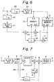
memory 3 is shown in Fig. 6. In Fig. 6, a digital video signal of 150 frames per second is supplied to an input terminal indicated atreference numeral 11. The 150 frames is the least common multiplied number of 25 frames and 30 frames. It is desirable that the input video signal is a standard signal in consideration of the formation of the mapping table. - The input video signal is supplied to thinning-
out circuits out circuit 26 forms a video signal of 30 frames per second by thinning out the input video signal to 1/5 in the time direction. The thinning-out circuit 28 forms a video signal of 25 frames per second. The output video signals of the thinning-out circuits segmentation circuits block segmentation circuit 27 converts the video signal of the order of the raster scan into the structure of the three-dimensional blocks of (2 x 2 x 6 frames). Theblock segmentation circuit 29 converts the video signal of the order of the raster scan into the structure of the three-dimensional blocks of (2 x 2 x 5 frames). - The output video signal from the
block segmentation circuit 29 is supplied to amemory 20 and afrequency memory 21 as their addresses. Thememory 20 has address spaces of 2¹⁶⁰ and data of (2 x 2 x 6 x 8 bits = 192 bits) is written into those addresses. Although thefrequency memory 21 also has the same address space as that of thememory 20, a frequency is written as data into the respective address. That is, read-out output of thememory 21 is supplied to anadder 22 and is increased by +1 and an output of theadder 22 is written to the same address in thememory 21. The contents of the addresses in thememories - The data of 192 bits read out from the
memory 20 is supplied to amultiplier 23 and is multiplied to a frequency read out from thefrequency memory 21. An output of themultiplier 23 is supplied to anadder 24 and is added to input data from theblock segmentation circuit 27 by theadder 24. An output of theadder 24 is supplied to adivider 25 as a dividend. The output of theadder 22 is supplied to thedivider 25 as a divisor. An output (quotient) of thedivider 25 is used as input data of thememory 20. - In the construction of Fig. 6 mentioned above, when a certain address Ai corresponding to one block of the SD video signal is first accessed, since the read-out outputs of the
memories memory 20 and a value in the corresponding address in thememory 21 is set to 1. When this address is again accessed after that, the output of theadder 22 is equal to 2 and the output of theadder 24 is equal to (X1 + X2) (X2 is the output of the delay circuit 13). Therefore, the output of thedivider 25 is equal to (X1 + X2)/2 and is written into thememory 20. On the other hand, afrequency 2 is written into thefrequency 21. Further, when the above address is after that, the data in thememory 20 is updated to (X1 + X2 + X3)/3 and the frequency is also updated to 3 by operations similar to the above. - By executing the operations mentioned above for a predetermined period of time, a mapping table indicative of the correlation between the block of the HD video signal and the block of the SD video signal which were formed from the same video signal is stored into the
memory 20. In other words, when a pattern of the data of the block of the SD video signal is given, a mapping table which generates the pattern of the block of the HD video signal which can correspond to such a pattern as an average can be formed. This mapping table is stored intomemory 3 of the construction of Fig. 3. - Fig. 7 shows still another embodiment of the present invention. This embodiment intends to reduce the capacity of the memory for formation and storage of the mapping table. The three-
dimensional ADRC encoder 6 is added to the output of theblock segmentation circuit 2. ADRC(Adaptive Dynamic Range Coding) is proposed by the present applicant. In ADRC, the bit number of each pixel is compressed from 8 bits to, for example, 4 bits by using the fact that plural pixels in a block have the time and spatial correlation. - The
ADRC encoder 6 comprises: a circuit for detecting a maximum value MAX, a minimum value MIN and a dynamic range DR represented with (MAX - MIN = DR) of pixel data of block, a circuit for generating a quantizing step by equally dividing the dynamic range DR by 2⁴, a subtracter for normarizing the pixel data of block by subtracting the minimum value MIN from the pixel data, and a quantizing circuit for dividing an output of the subtracter by the quantizing step i.e., requantizing. The dynamic range DR per block, the minimum value MIN and the four-bit code signal DT corresponding to each pixel are output from theADRC encoder 6. - The code signal DT of the output signals from the
ADRC encoder 6 is supplied to thememory 3 as the addresses. The video signal that frame number has been converted in accordance with the mapping table is read out from thememory 3. The dynamic range DR and the minimum value MIN of encoded outputs from theADRC encoder 6 are supplied to adelay circuit 7. The dynamic range DR of the output of thedelay circuit 7 is fed to adivider 8, and divided by 2⁴ = 16. Thus, the quantizing step of the block is obtained by thedivider 8. - The code signal of the block of the output image signal which is read out from the
memory 3 is supplied to amultiplier 9. Since the quantizing step is fed to themultiplier 9, the data after removing the minimum value is restored at themultiplier 9. The output signal of themultiplier 9 is supplied to anadder 10, and the minimum value MIN from thedelay circuit 7 is added. As a result, the restored data is fed to ablock separation circuit 4, and order of data is converted into the order of the raster scan. The output image data from the block separation circuit is taken out to anoutput terminal 5. - Since the example of the embodiment shown in Fig. 7 compresses the data per block by ADRC, the capacity of the
memory 3 can be reduced. In addition, the process for forming the mapping table is the same as the above except that the correlation between the ADRC encoded signals are detected. Thus, the capacity of thememory 3 for forming the mapping table can be reduced. It is needless to say that the embodiment in Fig. 7 can be similarly applied to a conversion for improving the spatial resolution in Fig. 3. - Fig. 8 shows an example of a construction to form the mapping table which is stored in the
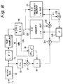
memory 3 in Fig. 7, when the embodiment in Fig. 7 is applied for improving the spatial resolution. In Fig. 8, a digital HD video signal is supplied to an input terminal shown byreference numeral 11. It is desirable that the HD video signal is a standard signal in consideration of the formation of the mapping table. For example, a signal comprising still images of various picture patterns can be used. The HD video signal can be actually obtained by photographing a standard image by an HD video camera or by recording an image pickup signal into an HDVTR. Further, when the HD video signal to be derived as a conversion output has previously been known, generality is not requested. Therefore, the mapping table is formed by using an original HD video signal. - The HD video signal is supplied to a
block segmentation circuit 12. Theblock segmentation circuit 12 converts the video signal of the order of the raster scan into the structure of the blocks of (4 x 4 x 8 bits). Two signals having different resolution and encoded by ADRC are formed from an output signal of theblock segmentation circuit 12. One of the two signals is a signal removing and requantizing the same resolution as that of the original HD video signal and is formed by thedelay circuit 13,subtracter 17,dividers ADRC encoder 16. A quantizing step formed at thedivider 18 is supplied to thedivider 19. As a result, a data of one pixel which is compressed into 4 bits is obtained. - The other signal is an SD video signal and is formed by a
low pass filter 14 and asub-sampling circuit 15 and the signal is encoded atADRC encoder 16. Thelow pass filter 14 is a two-dimensional digital filter and executes a band limit in the horizontal and vertical directions in order to prevent an aliasing distortion. Thesub-sampling circuit 15 performs the sampling such that the numbers of pixels in the horizontal and vertical directions are reduced into 1/2, respectively. Therefore, one block of the SD video signal from thesub-sampling circuit 15 corresponds to the data of (2 x 2 x 8 bits = 32 bits). The data is compressed (2 x 2 x 4 bits = 16 bits) at theADRC encoder 16. - The code signal DT from the
ADRC encoder 16 is supplied to amemory 20 and afrequency memory 21 as their addresses. Thememory 20 has address spaces of 2¹⁶ and data of (4 x 4 x 4 bits = 64 bits) is written into those addresses. Although thefrequency memory 21 also has the same address space as that of thememory 20, a frequency is written as data into the respective address. That is, read-out output of thememory 21 is supplied to anadder 22 and is increased by +1 and an output of theadder 22 is written in the same address in thememory 21. The contents of the addresses in thememories - The data of 128 bits read out from the
memory 20 is supplied to amultiplier 23 and is multiplied to a frequency read out from thefrequency memory 21. An output of themultiplier 23 is supplied to anadder 24 and is added to input data from thedelay circuit 13 by theadder 24. An output of theadder 24 is supplied to adivider 25 as a dividend. The output of theadder 22 is supplied to thedivider 25 as a divisor. An output (quotient) of thedivider 25 is used as input data of thememory 20. - In the construction of Fig. 8 mentioned above, when a certain address Ai corresponding to one block of the SD video signal is first accessed, since the read-out outputs of the
memories memory 20 and a value in the corresponding address in thememory 21 is set to 1. When this address is again accessed after that, the output of theadder 22 is equal to 2 and the output of theadder 24 is equal to (X1 + X2)(X2 is the output of the delay circuit 13). Therefore, the output of thedivider 25 is equal to (X1 + X2)/2 and is written into thememory 20. On the other hand, afrequency 2 is written into thefrequency 21. Further, when the above address is after that, the data in thememory 20 is updated to (X1 + X2 + X3)/3 and the frequency is also updated to 3 by operations similar to the above. - By executing the operations mentioned above for a predetermined period of time, a mapping table indicative of the correlation between the block of the HD video signal and the block of the SD video signal which were formed from the same video signal is stored into the
memory 20. In other words, when a pattern of the code signal of the block of the SD video signal is given, a mapping table which generates the pattern of the code signal of the block of the HD video signal which can correspond to such a pattern as an average can be formed This mapping table is stored intomemory 3 of the construction of Fig. 7. - In the process to form the mapping table mentioned above, the data cannot be actually written into all of the addresses in the
memory 20 and the addresses in which the data is equal to 0 can occur. In such a case, the interpolation is performed by the data predicted from the data which is not equal to 0 in the peripheral addresses. An example of a construction for such an interpolation is shown in Fig. 9. - In Fig. 9, a
memory 30 is a memory in which the mapping table formed as mentioned above has been stored. One of the addresses of 32 bits fromcounters circuit 33 as an address input of thememory 30. A clock CK from aninput terminal 34 is supplied to a clock input of thecounter 31 through agate circuit 35. The address from thecounter 31 is supplied to the switchingcircuit 33, anaddress memory 36, and a comparingcircuit 37. The clock CK from aninput terminal 38 is supplied to thecounter 32 and its output is supplied to the switchingcircuit 33 and comparingcircuit 37. An output of theaddress memory 36 is supplied to thecounter 32 as a present input. - Output data of the
memory 30 is supplied to a non-zero detectingcircuit 39 and a buffer memory (latch can be also used) 40 and is also supplied to an interpolation data forming circuit 42 through agate circuit 41. The interpolation data forming circuit 42 receives an output of thebuffer memory 40, an output of thegate circuit 41, an output of thecounter 31, and an output of theaddress memory 36 and forms the interpolation data in place of the zero data. The interpolation data is set to a data input of thememory 30. - A detection signal of the non-zero detecting
circuit 39 is supplied to a flip-flop 43 as a set input. The detection signal is further used to control the on/off operations of thegate circuit 41, to control the writing/reading operations of thebuffer memory 40 andaddress memory 36, and to control thecounter 32. - An output of the comparing
circuit 37 to compare the outputs of thecounters counter 32 and a reset terminal of the flip-flop 43. The on/off operations of thegate circuit 35, the switching operation of the switchingcircuit 33, and the writing operation of thememory 30 are controlled by an output signal of the flip-flop 43. - It is assumed that a part of the data stored in the
memory 30 is as shown in the following table 1 in order to explain the operation of the construction of the interpolation data formation in Fig. 9 mentioned above.[Table 1] Adress Data A0 D0 A1 D1 A2 D2 A3 0 A4 0 A5 D5 - A count value of the
counter 31 is first increased by the clock CK and address signals which are sequentially generated are supplied to thememory 30 through the switchingcircuit 33. The read-out data from thememory 30 is supplied to the non-zero detectingcircuit 39. In the case where the read-out data is not equal to 0, namely, when the data is obtained by a training image, the content on thebuffer memory 40 is read out and the output of thememory 30 is newly written into thebuffer memory 40. Further, thegate 41 is turned on and the output of thememory 30 is supplied to the interpolation data forming circuit 42. - When considering the timing at which data D5 in an address A5 in the
memory 30 was read out as in the example mentioned above, since it is not equal to 0, preceding non-zero data D2 is read out from thebuffer memory 40 by the detection signal of the non-zero detectingcircuit 39. The data D5 is written into thebuffer memory 40. The data D5 is supplied to the interpolation data forming circuit 42 through thegate circuit 41. The data D2 is also supplied to the interpolation data forming circuit 42. - On the other hand, since the address input to the
memory 30 in this instance is equal to A5, it is written into theaddress memory 36 by the non-zero detection signal. An address A2 which has already been stored before is read out from theaddress memory 36. Those addresses A2 and A5 are supplied to the interpolation data forming circuit 42. The interpolation data to be used in place of the zero data in addresses A3 and A4 between the data D2 and D5 is formed from the data D2 and D5 with reference to the addresses A2 and A5. - A weighting mean value corresponding to a distance is formed as interpolation data in this example. That is, a distance between the addresses A2 and A5 is set to 3 and the interpolation data in the address A3 is obtained as (2 D2 + D5)/3. The interpolation data in the address A4 is derived as (D2 + 2 D5)/3. As a forming method of the interpolation data, a curve fitting, a high-order interpolation, or the like can be used in addition to the above method.
- The address A2 from the
address memory 36 is loaded into thecounter 32 by the non-zero detection signal. The output of the counter 32 sequentially generates the addresses A3 and A4 by the clock CK. When the output of thecounter 32 reaches A5, the comparingcircuit 37 generates a coincidence output. Thecounter 32 is cleared and the flip-flop 43 is also reset by the coincidence output. - The switching
circuit 33 selects the addresses (A3, A4) from thecounter 32 and thememory 30 is set into the writing mode for a period of time during which the flip-flop 43 is set. Therefore, the interpolation data (2 D2 + D5)/3 and (D2 + 2 D5)/3 are respectively written into the addresses A3 and A4 in thememory 30. Thegate circuit 35 is turned off and the increment of thecounter 31 is stopped for this period of time. - For a period of time during which the flip-
flop 43 is reset, thegate circuit 35 is turned on, the switchingcircuit 33 selects the address from thecounter 31, and thememory 30 is set into the reading mode. Operations similar to those mentioned above are subsequently executed. - Although the embodiment mentioned above relates to the example in which the SD video signal is up converted into the HD video signal, the invention can be also similarly applied to the enlargement of an image in addition to the above example.
- It is to be understood that, while a number of embodiments have been described above, various changes and modifications may be effected therein by one skilled in the art without departing from the scope of the invention.
- From the above, it will be seen that, since the high resolution component is reconstructed by using the correlation between the low resolution image and the high resolution image, the standard video signal is converted into the high resolution image and can be displayed on the HD monitor. The image can be also enlarged to an arbitrary size without deteriorating the resolution. The image can be, further, thinned out and compressed without a deterioration of the resolution.
Claims (8)
- A digital video signal converting apparatus for converting a first digital video signal having a first resolution to a second digital video signal having a second resolution higher than said first resolution, comprising:
block segmentation means for converting said first digital video signal into a block format,
memory means having a mapping table stored therein and having address terminals to which said first digital video signal in a block format is supplied and output terminals from which said second digital video signal in block format is output, and
block separation means for converting said second digital video signal in a block format into a digital video signal in a raster scan order,
wherein said mapping table in said memory means is generated by training utilizing a plurality of images said training step being performed by generating first and second digital video signal corresponding to each of said plurality of images, converting each of said first and second digital video signals into a block format, and selecting said first digital video signal in a block format is an address signal for said mapping table and inputting said second digital video signal in a block format to a memory area corresponding to said address, and generating data of the mapping table from the signal stored in said memory area. - A digital video signal converting apparatus according to claim 1, wherein said first and second resolutions are spatial resolutions.
- A digital video signal converting apparatus according to claim 2, wherein said first digital video signal is a signal in accordance with NTSC standard, and said second digital video signal is a signal in accordance with HD standard.
- A digital video signal converting apparatus according to claim 1, wherein said first and second resolutions are time resolutions.
- A digital video signal converting apparatus according to claim 4, wherein said first digital video signal is a signal in accordance with PAL standard, and said second digital video signal is a signal in accordance with NTSC standard.
- A digital video signal converting apparatus according to claim 1, wherein block segmentation means includes block compression coding means, and block separation means includes block decoding means.
- A digital video signal converting apparatus according to claim 6, wherein said block compression coding means is an ADRC encoder.
- A digital video signal converting apparatus according to claim 1, wherein said training step includes a step which interpolates the data in the address area of the mapping table having no data.
Applications Claiming Priority (2)
| Application Number | Priority Date | Filing Date | Title |
|---|---|---|---|
| JP352300/91 | 1991-12-13 | ||
| JP35230091A JP3278881B2 (en) | 1991-12-13 | 1991-12-13 | Image signal generator |
Publications (3)
| Publication Number | Publication Date |
|---|---|
| EP0546845A2 true EP0546845A2 (en) | 1993-06-16 |
| EP0546845A3 EP0546845A3 (en) | 1993-12-08 |
| EP0546845B1 EP0546845B1 (en) | 1997-06-11 |
Family
ID=18423123
Family Applications (1)
| Application Number | Title | Priority Date | Filing Date |
|---|---|---|---|
| EP19920311324 Expired - Lifetime EP0546845B1 (en) | 1991-12-13 | 1992-12-11 | Digital video signal converting apparatus |
Country Status (5)
| Country | Link |
|---|---|
| US (1) | US5379072A (en) |
| EP (1) | EP0546845B1 (en) |
| JP (1) | JP3278881B2 (en) |
| KR (1) | KR100254958B1 (en) |
| DE (1) | DE69220337T2 (en) |
Cited By (7)
| Publication number | Priority date | Publication date | Assignee | Title |
|---|---|---|---|---|
| EP0820197A2 (en) * | 1996-07-17 | 1998-01-21 | Sony Corporation | Image coding and decoding using mapping coefficients corresponding to class information of pixel blocks |
| EP0820195A2 (en) * | 1996-07-17 | 1998-01-21 | Sony Corporation | Image coding method using subsampling and interpolation based on classes of pixel blocks |
| EP0820198A2 (en) * | 1996-07-17 | 1998-01-21 | Sony Corporation | Apparatus and method for image coding and decoding |
| US6192076B1 (en) | 1996-07-17 | 2001-02-20 | Sony Corporation | Image coding and decoding using mapping coefficients corresponding to class information of pixel blocks |
| EP1298934A1 (en) * | 1996-07-17 | 2003-04-02 | Sony Corporation | Apparatus and method for image coding and decoding |
| EP1793316A3 (en) * | 1994-05-28 | 2007-08-08 | Sony Corporation | Digital signal processing |
| GB2449631A (en) * | 2007-05-21 | 2008-12-03 | Dooworks Fz Co | Transcoding of Very High Definition(XHD) images for processing as HD images. |
Families Citing this family (81)
| Publication number | Priority date | Publication date | Assignee | Title |
|---|---|---|---|---|
| EP0645736B1 (en) * | 1993-09-27 | 2003-02-05 | Canon Kabushiki Kaisha | Image processing apparatus |
| US5666163A (en) * | 1994-07-12 | 1997-09-09 | Sony Corporation | Electronic image resolution enhancement by frequency-domain extrapolation |
| US5512953A (en) * | 1994-08-09 | 1996-04-30 | At&T Corp. | Method and apparatus for conversion of compressed bit stream representation of video signal |
| DE69524202T2 (en) * | 1994-08-31 | 2002-07-04 | Sony Corp | RECORDING DEVICE |
| GB9504307D0 (en) * | 1995-03-03 | 1995-04-19 | Philips Electronics Uk Ltd | Video image processing |
| TW330273B (en) * | 1996-02-13 | 1998-04-21 | Sanyo Electric Co | The image-processing device and method for mapping image memory |
| US6298085B1 (en) | 1997-10-23 | 2001-10-02 | Sony Corporation | Source encoding using shuffling of data to provide robust error recovery in a burst error-environment |
| US6282684B1 (en) | 1997-10-23 | 2001-08-28 | Sony Corporation | Apparatus and method for recovery of data in a lossy transmission environment |
| US6581170B1 (en) | 1997-10-23 | 2003-06-17 | Sony Corporation | Source coding to provide for robust error recovery during transmission losses |
| KR100657776B1 (en) | 1998-09-30 | 2006-12-15 | 소니 가부시끼 가이샤 | Arithmetic Device, Converter, And Their Methods |
| US6178266B1 (en) | 1999-02-12 | 2001-01-23 | Sony Corporation | Method and apparatus for the recovery of compression constants in the encoded domain |
| US6154761A (en) * | 1999-02-12 | 2000-11-28 | Sony Corporation | Classified adaptive multiple processing system |
| US6519369B1 (en) | 1999-02-12 | 2003-02-11 | Sony Corporation | Method and apparatus for filter tap expansion |
| US6170074B1 (en) | 1999-02-12 | 2001-01-02 | Sony Corporation | Source coding to provide for robust error recovery |
| US7010737B2 (en) * | 1999-02-12 | 2006-03-07 | Sony Corporation | Method and apparatus for error data recovery |
| US6621936B1 (en) | 1999-02-12 | 2003-09-16 | Sony Corporation | Method and apparatus for spatial class reduction |
| US6307979B1 (en) | 1999-02-12 | 2001-10-23 | Sony Corporation | Classified adaptive error recovery method and apparatus |
| US6591398B1 (en) | 1999-02-12 | 2003-07-08 | Sony Corporation | Multiple processing system |
| US6535148B1 (en) | 1999-02-12 | 2003-03-18 | Sony Corporation | Method and apparatus for truncated decoding |
| US6151416A (en) * | 1999-02-12 | 2000-11-21 | Sony Corporation | Method and apparatus for adaptive class tap selection according to multiple classification |
| US6363118B1 (en) | 1999-02-12 | 2002-03-26 | Sony Corporation | Apparatus and method for the recovery of compression constants in the encoded domain |
| US6192161B1 (en) | 1999-02-12 | 2001-02-20 | Sony Corporation | Method and apparatus for adaptive filter tap selection according to a class |
| US6307560B1 (en) | 1999-02-12 | 2001-10-23 | Sony Corporation | Classified adaptive spatio-temporal format conversion method and apparatus |
| US7730300B2 (en) * | 1999-03-30 | 2010-06-01 | Sony Corporation | Method and apparatus for protecting the transfer of data |
| US7565546B2 (en) | 1999-03-30 | 2009-07-21 | Sony Corporation | System, method and apparatus for secure digital content transmission |
| US6697489B1 (en) * | 1999-03-30 | 2004-02-24 | Sony Corporation | Method and apparatus for securing control words |
| US6549672B1 (en) * | 1999-06-29 | 2003-04-15 | Sony Corporation | Method and apparatus for recovery of encoded data using central value |
| US6493842B1 (en) | 1999-06-29 | 2002-12-10 | Sony Corporation | Time-varying randomization for data synchronization and implicit information transmission |
| US6389562B1 (en) | 1999-06-29 | 2002-05-14 | Sony Corporation | Source code shuffling to provide for robust error recovery |
| US6473876B1 (en) | 1999-06-29 | 2002-10-29 | Sony Corporation | Method and apparatus for encoding of bitstreams using rotation |
| US6522785B1 (en) | 1999-09-24 | 2003-02-18 | Sony Corporation | Classified adaptive error recovery method and apparatus |
| US6351494B1 (en) | 1999-09-24 | 2002-02-26 | Sony Corporation | Classified adaptive error recovery method and apparatus |
| US6539517B1 (en) | 1999-11-09 | 2003-03-25 | Sony Corporation | Data transformation for explicit transmission of control information |
| US7039614B1 (en) | 1999-11-09 | 2006-05-02 | Sony Corporation | Method for simulcrypting scrambled data to a plurality of conditional access devices |
| US6754371B1 (en) | 1999-12-07 | 2004-06-22 | Sony Corporation | Method and apparatus for past and future motion classification |
| US7225164B1 (en) * | 2000-02-15 | 2007-05-29 | Sony Corporation | Method and apparatus for implementing revocation in broadcast networks |
| US20030206631A1 (en) * | 2000-06-22 | 2003-11-06 | Candelore Brant L. | Method and apparatus for scrambling program data for furture viewing |
| US20040205812A1 (en) * | 2000-06-22 | 2004-10-14 | Candelore Brant L. | Method and apparatus for routing program data in a program viewing unit |
| US7350082B2 (en) * | 2001-06-06 | 2008-03-25 | Sony Corporation | Upgrading of encryption |
| US7747853B2 (en) | 2001-06-06 | 2010-06-29 | Sony Corporation | IP delivery of secure digital content |
| US7139398B2 (en) | 2001-06-06 | 2006-11-21 | Sony Corporation | Time division partial encryption |
| US7895616B2 (en) * | 2001-06-06 | 2011-02-22 | Sony Corporation | Reconstitution of program streams split across multiple packet identifiers |
| US7242773B2 (en) * | 2002-09-09 | 2007-07-10 | Sony Corporation | Multiple partial encryption using retuning |
| US7218738B2 (en) * | 2002-01-02 | 2007-05-15 | Sony Corporation | Encryption and content control in a digital broadcast system |
| US7302059B2 (en) * | 2002-01-02 | 2007-11-27 | Sony Corporation | Star pattern partial encryption |
| US7765567B2 (en) * | 2002-01-02 | 2010-07-27 | Sony Corporation | Content replacement by PID mapping |
| US7292691B2 (en) | 2002-01-02 | 2007-11-06 | Sony Corporation | Progressive video refresh slice detection |
| US7155012B2 (en) * | 2002-01-02 | 2006-12-26 | Sony Corporation | Slice mask and moat pattern partial encryption |
| US7376233B2 (en) * | 2002-01-02 | 2008-05-20 | Sony Corporation | Video slice and active region based multiple partial encryption |
| US7039938B2 (en) * | 2002-01-02 | 2006-05-02 | Sony Corporation | Selective encryption for video on demand |
| US7233669B2 (en) * | 2002-01-02 | 2007-06-19 | Sony Corporation | Selective encryption to enable multiple decryption keys |
| US7215770B2 (en) * | 2002-01-02 | 2007-05-08 | Sony Corporation | System and method for partially encrypted multimedia stream |
| US7823174B2 (en) * | 2002-01-02 | 2010-10-26 | Sony Corporation | Macro-block based content replacement by PID mapping |
| US20090180025A1 (en) * | 2002-05-28 | 2009-07-16 | Sony Corporation | Method and apparatus for overlaying graphics on video |
| US7530084B2 (en) * | 2002-05-28 | 2009-05-05 | Sony Corporation | Method and apparatus for synchronizing dynamic graphics |
| US8818896B2 (en) * | 2002-09-09 | 2014-08-26 | Sony Corporation | Selective encryption with coverage encryption |
| US8572408B2 (en) | 2002-11-05 | 2013-10-29 | Sony Corporation | Digital rights management of a digital device |
| US7724907B2 (en) | 2002-11-05 | 2010-05-25 | Sony Corporation | Mechanism for protecting the transfer of digital content |
| US8667525B2 (en) * | 2002-12-13 | 2014-03-04 | Sony Corporation | Targeted advertisement selection from a digital stream |
| US8645988B2 (en) * | 2002-12-13 | 2014-02-04 | Sony Corporation | Content personalization for digital content |
| US20040165586A1 (en) * | 2003-02-24 | 2004-08-26 | Read Christopher Jensen | PID filters based network routing |
| US7409702B2 (en) * | 2003-03-20 | 2008-08-05 | Sony Corporation | Auxiliary program association table |
| US7292692B2 (en) | 2003-03-25 | 2007-11-06 | Sony Corporation | Content scrambling with minimal impact on legacy devices |
| US20050036067A1 (en) * | 2003-08-05 | 2005-02-17 | Ryal Kim Annon | Variable perspective view of video images |
| US7286667B1 (en) | 2003-09-15 | 2007-10-23 | Sony Corporation | Decryption system |
| US20050066357A1 (en) * | 2003-09-22 | 2005-03-24 | Ryal Kim Annon | Modifying content rating |
| US20050097596A1 (en) * | 2003-10-31 | 2005-05-05 | Pedlow Leo M.Jr. | Re-encrypted delivery of video-on-demand content |
| US7853980B2 (en) * | 2003-10-31 | 2010-12-14 | Sony Corporation | Bi-directional indices for trick mode video-on-demand |
| US7343013B2 (en) * | 2003-12-16 | 2008-03-11 | Sony Corporation | Composite session-based encryption of video on demand content |
| US7263187B2 (en) * | 2003-10-31 | 2007-08-28 | Sony Corporation | Batch mode session-based encryption of video on demand content |
| US20050097597A1 (en) * | 2003-10-31 | 2005-05-05 | Pedlow Leo M.Jr. | Hybrid storage of video on demand content |
| US7620180B2 (en) * | 2003-11-03 | 2009-11-17 | Sony Corporation | Preparation of content for multiple conditional access methods in video on demand |
| US7346163B2 (en) * | 2003-10-31 | 2008-03-18 | Sony Corporation | Dynamic composition of pre-encrypted video on demand content |
| US20050102702A1 (en) * | 2003-11-12 | 2005-05-12 | Candelore Brant L. | Cablecard with content manipulation |
| US20050169473A1 (en) * | 2004-02-03 | 2005-08-04 | Candelore Brant L. | Multiple selective encryption with DRM |
| US8041190B2 (en) | 2004-12-15 | 2011-10-18 | Sony Corporation | System and method for the creation, synchronization and delivery of alternate content |
| US7895617B2 (en) * | 2004-12-15 | 2011-02-22 | Sony Corporation | Content substitution editor |
| US8185921B2 (en) | 2006-02-28 | 2012-05-22 | Sony Corporation | Parental control of displayed content using closed captioning |
| US7555464B2 (en) * | 2006-03-01 | 2009-06-30 | Sony Corporation | Multiple DRM management |
| WO2007139067A1 (en) | 2006-05-29 | 2007-12-06 | Panasonic Corporation | Image high-resolution upgrading device, image high-resolution upgrading method, image high-resolution upgrading program and image high-resolution upgrading system |
| US11822158B2 (en) | 2019-09-11 | 2023-11-21 | Brightview Technologies, Inc. | Back light unit for backlit displays |
Citations (1)
| Publication number | Priority date | Publication date | Assignee | Title |
|---|---|---|---|---|
| EP0414596A1 (en) * | 1989-08-22 | 1991-02-27 | Laboratoire Europeen De Recherches Electroniques Avancees | Device for converting the field frequency and line number in a high definition television receiver |
Family Cites Families (4)
| Publication number | Priority date | Publication date | Assignee | Title |
|---|---|---|---|---|
| US4442454A (en) * | 1982-11-15 | 1984-04-10 | Eastman Kodak Company | Image processing method using a block overlap transformation procedure |
| JP2508439B2 (en) * | 1987-05-29 | 1996-06-19 | ソニー株式会社 | High efficiency encoder |
| US5161014A (en) * | 1990-11-26 | 1992-11-03 | Rca Thomson Licensing Corporation | Neural networks as for video signal processing |
| US5113256A (en) * | 1991-02-08 | 1992-05-12 | Zenith Electronics Corporation | Method of perceptually modeling a video image signal |
-
1991
- 1991-12-13 JP JP35230091A patent/JP3278881B2/en not_active Expired - Lifetime
-
1992
- 1992-12-08 US US07/986,707 patent/US5379072A/en not_active Expired - Lifetime
- 1992-12-11 DE DE1992620337 patent/DE69220337T2/en not_active Expired - Lifetime
- 1992-12-11 KR KR1019920023958A patent/KR100254958B1/en not_active IP Right Cessation
- 1992-12-11 EP EP19920311324 patent/EP0546845B1/en not_active Expired - Lifetime
Patent Citations (1)
| Publication number | Priority date | Publication date | Assignee | Title |
|---|---|---|---|---|
| EP0414596A1 (en) * | 1989-08-22 | 1991-02-27 | Laboratoire Europeen De Recherches Electroniques Avancees | Device for converting the field frequency and line number in a high definition television receiver |
Non-Patent Citations (2)
| Title |
|---|
| SIGNAL PROCESSING OF HDTV, II 30 August 1989, TURIN (IT) pages 665 - 673 , XP215284 M. SAKURAI 'NTSC-HDTV Up-converter.' * |
| SMPTE JOURNAL vol. 98, no. 6, June 1989, SCARSDALE, NY US pages 420 - 424 P. ROBERT ET AL. 'Advanced High-Definition 50 to 60-Hz Standards Conversion.' * |
Cited By (20)
| Publication number | Priority date | Publication date | Assignee | Title |
|---|---|---|---|---|
| EP1793316A3 (en) * | 1994-05-28 | 2007-08-08 | Sony Corporation | Digital signal processing |
| EP1755044A3 (en) * | 1994-05-28 | 2007-08-08 | Sony Corporation | Digital signal processing |
| EP1755045A3 (en) * | 1994-05-28 | 2007-08-08 | Sony Corporation | Digital signal processing |
| EP0820195A3 (en) * | 1996-07-17 | 2000-04-12 | Sony Corporation | Image coding method using subsampling and interpolation based on classes of pixel blocks |
| EP1298934A1 (en) * | 1996-07-17 | 2003-04-02 | Sony Corporation | Apparatus and method for image coding and decoding |
| EP0820197A2 (en) * | 1996-07-17 | 1998-01-21 | Sony Corporation | Image coding and decoding using mapping coefficients corresponding to class information of pixel blocks |
| US6192076B1 (en) | 1996-07-17 | 2001-02-20 | Sony Corporation | Image coding and decoding using mapping coefficients corresponding to class information of pixel blocks |
| US6198770B1 (en) | 1996-07-17 | 2001-03-06 | Sony Corporation | Image coding and decoding using mapping coefficients corresponding to class information of pixel blocks |
| SG80578A1 (en) * | 1996-07-17 | 2001-05-22 | Sony Corp | Image coding apparatus, image coding method, image decoding method, image decoding apparatus, image data transmitting method and recording medium |
| SG80576A1 (en) * | 1996-07-17 | 2001-05-22 | Sony Corp | Image coding and decoding using mapping coefficients corresponding to class information of pixel blocks |
| US6381369B1 (en) | 1996-07-17 | 2002-04-30 | Sony Corporation | Image coding apparatus, image coding method, image decoding method, image decoding apparatus, image data transmitting method and recording medium |
| US6477278B1 (en) | 1996-07-17 | 2002-11-05 | Sony Corporation | Image coding apparatus, image coding method, image decoding method, image decoding apparatus, image data transmitting method and recording medium |
| EP0820197A3 (en) * | 1996-07-17 | 2000-04-12 | Sony Corporation | Image coding and decoding using mapping coefficients corresponding to class information of pixel blocks |
| US6970508B1 (en) | 1996-07-17 | 2005-11-29 | Sony Corporation | Image coding and decoding using mapping coefficients corresponding to class information of pixel blocks |
| EP0820198A3 (en) * | 1996-07-17 | 2000-04-12 | Sony Corporation | Apparatus and method for image coding and decoding |
| EP0820198A2 (en) * | 1996-07-17 | 1998-01-21 | Sony Corporation | Apparatus and method for image coding and decoding |
| EP0820195A2 (en) * | 1996-07-17 | 1998-01-21 | Sony Corporation | Image coding method using subsampling and interpolation based on classes of pixel blocks |
| GB2449631A (en) * | 2007-05-21 | 2008-12-03 | Dooworks Fz Co | Transcoding of Very High Definition(XHD) images for processing as HD images. |
| GB2449631B (en) * | 2007-05-21 | 2012-02-15 | Doo Technologies Fze | Method and system for processing of images |
| US9478011B2 (en) | 2007-05-21 | 2016-10-25 | Doo Technologies Fzco | Method and system for processing of images |
Also Published As
| Publication number | Publication date |
|---|---|
| KR100254958B1 (en) | 2000-05-01 |
| JP3278881B2 (en) | 2002-04-30 |
| EP0546845A3 (en) | 1993-12-08 |
| KR930015857A (en) | 1993-07-24 |
| US5379072A (en) | 1995-01-03 |
| DE69220337D1 (en) | 1997-07-17 |
| DE69220337T2 (en) | 1997-11-20 |
| EP0546845B1 (en) | 1997-06-11 |
| JPH05167993A (en) | 1993-07-02 |
Similar Documents
| Publication | Publication Date | Title |
|---|---|---|
| EP0546845B1 (en) | Digital video signal converting apparatus | |
| JP3438233B2 (en) | Image conversion apparatus and method | |
| US5374958A (en) | Image compression based on pattern fineness and edge presence | |
| US5444483A (en) | Digital electronic camera apparatus for recording still video images and motion video images | |
| US5193003A (en) | Apparatus for decoding digital video data with small memory requirement | |
| JPH1175180A (en) | Image processing device and method, and transmission medium and method | |
| EP0614316A2 (en) | Apparatus and method for moving picture coding | |
| JP2782766B2 (en) | Video / still image conversion method | |
| JP3278882B2 (en) | Image signal generator | |
| JP3278880B2 (en) | Image signal generator | |
| JP3608544B2 (en) | Parameter generating apparatus and method | |
| JP3988738B2 (en) | Image conversion apparatus and image conversion method | |
| JP3271109B2 (en) | Digital image signal processing apparatus and processing method | |
| JP2668881B2 (en) | High-efficiency coding device for image signals | |
| Murata et al. | A consumer use flicker free color monitor using digital signal processing | |
| US6002837A (en) | Image reproducing apparatus reproducing coded image signals while concealing data which cannot be decoded | |
| JP3455263B2 (en) | Image processing device | |
| JP2968536B2 (en) | Electronic still camera | |
| JP2531236B2 (en) | Image signal processing circuit | |
| JP4109328B2 (en) | Video signal encoding device | |
| JP2994643B2 (en) | Image transmission apparatus and method | |
| JP2531240B2 (en) | Image signal processing circuit | |
| JP2002199393A (en) | Digital picture signal processor and its method | |
| JP2000004436A (en) | Picture processing unit, picture processing method, transmission medium and transmission method | |
| JPH0759060A (en) | Interpolation device for compressed high resolution video signal |
Legal Events
| Date | Code | Title | Description |
|---|---|---|---|
| PUAI | Public reference made under article 153(3) epc to a published international application that has entered the european phase |
Free format text: ORIGINAL CODE: 0009012 |
|
| AK | Designated contracting states |
Kind code of ref document: A2 Designated state(s): DE FR GB |
|
| PUAL | Search report despatched |
Free format text: ORIGINAL CODE: 0009013 |
|
| AK | Designated contracting states |
Kind code of ref document: A3 Designated state(s): DE FR GB |
|
| 17P | Request for examination filed |
Effective date: 19940421 |
|
| GRAG | Despatch of communication of intention to grant |
Free format text: ORIGINAL CODE: EPIDOS AGRA |
|
| 17Q | First examination report despatched |
Effective date: 19960610 |
|
| GRAH | Despatch of communication of intention to grant a patent |
Free format text: ORIGINAL CODE: EPIDOS IGRA |
|
| GRAH | Despatch of communication of intention to grant a patent |
Free format text: ORIGINAL CODE: EPIDOS IGRA |
|
| GRAH | Despatch of communication of intention to grant a patent |
Free format text: ORIGINAL CODE: EPIDOS IGRA |
|
| GRAA | (expected) grant |
Free format text: ORIGINAL CODE: 0009210 |
|
| AK | Designated contracting states |
Kind code of ref document: B1 Designated state(s): DE FR GB |
|
| REF | Corresponds to: |
Ref document number: 69220337 Country of ref document: DE Date of ref document: 19970717 |
|
| ET | Fr: translation filed | ||
| PLBE | No opposition filed within time limit |
Free format text: ORIGINAL CODE: 0009261 |
|
| STAA | Information on the status of an ep patent application or granted ep patent |
Free format text: STATUS: NO OPPOSITION FILED WITHIN TIME LIMIT |
|
| 26N | No opposition filed | ||
| REG | Reference to a national code |
Ref country code: GB Ref legal event code: IF02 |
|
| REG | Reference to a national code |
Ref country code: GB Ref legal event code: 746 Effective date: 20091124 |
|
| REG | Reference to a national code |
Ref country code: GB Ref legal event code: S47 Free format text: CANCELLATION OF ENTRY; APPLICATION BY FILING PATENTS FORM 15 WITHIN 4 WEEKS FROM THE DATE OF PUBLICATION OF THIS JOURNAL |
|
| PGFP | Annual fee paid to national office [announced via postgrant information from national office to epo] |
Ref country code: GB Payment date: 20101221 Year of fee payment: 19 |
|
| PGFP | Annual fee paid to national office [announced via postgrant information from national office to epo] |
Ref country code: FR Payment date: 20120105 Year of fee payment: 20 |
|
| PGFP | Annual fee paid to national office [announced via postgrant information from national office to epo] |
Ref country code: DE Payment date: 20111222 Year of fee payment: 20 |
|
| REG | Reference to a national code |
Ref country code: DE Ref legal event code: R071 Ref document number: 69220337 Country of ref document: DE |
|
| REG | Reference to a national code |
Ref country code: DE Ref legal event code: R071 Ref document number: 69220337 Country of ref document: DE |
|
| REG | Reference to a national code |
Ref country code: GB Ref legal event code: PE20 Expiry date: 20121210 |
|
| PG25 | Lapsed in a contracting state [announced via postgrant information from national office to epo] |
Ref country code: GB Free format text: LAPSE BECAUSE OF EXPIRATION OF PROTECTION Effective date: 20121210 |