EP0547323A1 - Branching device for light wave guides - Google Patents
Branching device for light wave guides Download PDFInfo
- Publication number
- EP0547323A1 EP0547323A1 EP92117494A EP92117494A EP0547323A1 EP 0547323 A1 EP0547323 A1 EP 0547323A1 EP 92117494 A EP92117494 A EP 92117494A EP 92117494 A EP92117494 A EP 92117494A EP 0547323 A1 EP0547323 A1 EP 0547323A1
- Authority
- EP
- European Patent Office
- Prior art keywords
- cable
- branch
- tap
- branching device
- subscriber
- Prior art date
- Legal status (The legal status is an assumption and is not a legal conclusion. Google has not performed a legal analysis and makes no representation as to the accuracy of the status listed.)
- Granted
Links
Images
Classifications
-
- G—PHYSICS
- G02—OPTICS
- G02B—OPTICAL ELEMENTS, SYSTEMS OR APPARATUS
- G02B6/00—Light guides; Structural details of arrangements comprising light guides and other optical elements, e.g. couplings
- G02B6/24—Coupling light guides
- G02B6/36—Mechanical coupling means
- G02B6/38—Mechanical coupling means having fibre to fibre mating means
- G02B6/3801—Permanent connections, i.e. wherein fibres are kept aligned by mechanical means
-
- G—PHYSICS
- G02—OPTICS
- G02B—OPTICAL ELEMENTS, SYSTEMS OR APPARATUS
- G02B6/00—Light guides; Structural details of arrangements comprising light guides and other optical elements, e.g. couplings
- G02B6/44—Mechanical structures for providing tensile strength and external protection for fibres, e.g. optical transmission cables
- G02B6/4439—Auxiliary devices
- G02B6/444—Systems or boxes with surplus lengths
-
- G—PHYSICS
- G02—OPTICS
- G02B—OPTICAL ELEMENTS, SYSTEMS OR APPARATUS
- G02B6/00—Light guides; Structural details of arrangements comprising light guides and other optical elements, e.g. couplings
- G02B6/44—Mechanical structures for providing tensile strength and external protection for fibres, e.g. optical transmission cables
- G02B6/4439—Auxiliary devices
- G02B6/4471—Terminating devices ; Cable clamps
- G02B6/4472—Manifolds
Landscapes
- Physics & Mathematics (AREA)
- General Physics & Mathematics (AREA)
- Optics & Photonics (AREA)
- Light Guides In General And Applications Therefor (AREA)
- Mechanical Coupling Of Light Guides (AREA)
Abstract
Description
Die Erfindung betrifft eine LWL-Verzweigungseinrichtung nach dem Oberbegriff des Anspruchs 1. Nach der Verlegung eines optischen Kabels im Erdreich ist es gelegentlich notwendig, an einer bestimmten Stelle eine Stichleitung beispielsweise zu einem Haus zu führen und neue Teilnehmer anzuschließen. Zu diesem Zweck wird das Kabel auf einer bestimmten Strecke freigelegt und eine Spleißung an mindestens einer optischen Faser vorgenommen. Es wird zunehmend zur Regel, in Ortsnetzen Glasfasern zumindest zusätzlich zu vorhandenen Nachrichtenleitungen aus Kupfer zu verlegen.The invention relates to an optical fiber branching device according to the preamble of
LWL-Verzweigungen sind in vielen Ausführungsformen bekannt. Im Verzweigungsbereich zu Teilnehmern im Ortsnetz ist es nötig, daß eine Verzweigung des Hauptkabels vorgenommen wird. Dieses Hauptkabel liegt hier in Form eines Stegkabels mit im allgemeinen mehr als vier parallelen LWL-Adern vor. Aus dem Steg- oder Flachkabel werden in an sich bekannter Weise Kabelstränge herausgetrennt und direkt zum Haus hin verlegt. Ein solcher Abzweiger ist aus der DE-A1 36 30 659 bekannt.FO branches are known in many embodiments. In the branch area to subscribers in the local network, it is necessary for the main cable to be branched. This main cable is in the form of a web cable with generally more than four parallel fiber optic wires. Cable strands are separated from the web or flat cable in a manner known per se and laid directly to the house. Such a tap is known from DE-A1 36 30 659.
In einem zukünftigen Ortsnetz in Glasfasertechnik ist eine Vielzahl von Teilnehmeranschlüssen zu realisieren. Dies bedeutet eine große Anzahl von Abzweigpunkten von einem Verteilkabel zu den einzelnen Häusern. Stand der Technik ist dabei der Einsatz von Aufteilmuffen. Diese sind groß und man benötigt zum Verspleißen der Fasern eine Absetzlänge des Kabels von ca. 2 m; dementsprechend groß müssen auch die Baugruben ausgehoben werden. Bei der Erstverlegung spielt dies keine große Rolle; bei einem späteren Ausbau jedoch fallen teuere Erdarbeiten an, um die benötigte Faserreserve zu erhalten. Eine Möglichkeit, dies zu umgehen, besteht darin, schon beim Erstausbau Reserve in Form von Schleifen in die Erde zu legen. Aus planerischen Gesichtspunkten ist diese Lösung nicht günstig.A large number of subscriber connections can be implemented in a future local network using fiber optic technology. This means a large number of branch points from a distribution cable to the individual houses. The state of the art is the use of distribution sleeves. These are large and you need a stripping length of approx. 2 m for splicing the fibers; the excavation pits must be excavated accordingly. This does not play a major role in the first installation; however, later expansion will require expensive earthworks to maintain the fiber reserve required. One way to get around this is to put a reserve in the form of loops when it is first installed. From a planning point of view, this solution is not cheap.
Zur Zeit erfolgt die Faserverbindung in Muffen, wie sie in der DE-A1 36 25 888 beschrieben sind und mit Hilfe thermischer Spleißvorrichtungen. Diese Geräte sind teuer und benötigen gut geschultes Personal.At the moment the fiber connection takes place in sleeves as described in DE-A1 36 25 888 and with the help of thermal splicing devices. These devices are expensive and require well-trained personnel.
Der Erfindung liegt die Aufgabe zugrunde, eine Abzweigung für optische Adern nach dem Oberbegriff des Anspruchs 1 zu schaffen, welche zusätzlichen Teilnehmern eine Anschlußmöglichkeit bietet, und dabei mit einer kleinen freigelegten Kabellänge auskommt.The invention has for its object to provide a branch for optical wires according to the preamble of
Der Vorteil der Erfindung liegt darin, daß man die Grabarbeiten auf ein sehr viel kleineres Loch beschränken kann, was erhebliche Einsparungen zufolge hat. Außerdem ist es in vielen Fällen wegen der örtlichen Gegebenheiten kaum möglich, ein 2 m langes Stück Kabel freizulegen. Bei der hier vorgeschlagenen Technik wird die auszuhebende Grube etwa die Maße 1 x 1 m² besitzen.The advantage of the invention is that the digging work can be limited to a much smaller hole, which has considerable savings. In addition, in many cases, due to the local conditions, it is hardly possible to expose a 2 m long piece of cable. In the technique proposed here, the pit to be excavated will have the dimensions 1 x 1 m².
Die Nachteile des Standes der Technik bestehen darin, daß man etwa 2 m des Kabels abmantelt und die optischen Fasern etwa in dieser Länge zu entnehmen hat. Aus diesen 2 m Faservorrat werden wesentliche Teile in einer Spleißkassette bevorratet. Die Fasern werden thermisch zusammengeschweißt, wobei die Vorratslänge in der Spleißkassette jeweils zum Erneuern der Spleißverbindung benutzt werden kann. Diese Lösung ist jedoch in der Praxis viel zu aufwendig und teuer.The disadvantages of the prior art are that about 2 m of the cable is stripped and the optical fibers have to be removed in this length. Essential parts from this 2 m fiber supply are stored in a splice cassette. The fibers are thermally welded together, and the length of the stock in the splice cassette can be used to renew the splice connection. In practice, however, this solution is far too complex and expensive.
Die Erfindung wird nachstehend anhand der Zeichnung näher erläutert. Dabei zeigt
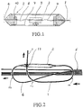
Figur 1- einen Schnitt durch einen Abzweiger nach der Erfindung und
Figur 2- ein Ausführungsbeispiel der Verzweigungseinrichtung.
- Figure 1
- a section through a tap according to the invention and
- Figure 2
- an embodiment of the branching device.
Aus dem Hauptkabel 5 gewinnt man etwa 1 m an Vorratslänge, welche zum Anfertigen einer mechanischen Spleißverbindung auch dann ausreichend ist, wenn beim Spleißen die dazu notwendigen Prozeduren nicht sofort zu einem optisch einwandfreien Ergebnis führen und wiederholt werden müssen. Der Abzweiger 2 enthält einen oder mehrere mechanische Spleiße 3, welcher die optischen Fasern 4 und 8 miteinander verbindet. Der Abzweiger 2 besteht aus einem Rohrstück 7, welches in zwei Hälften geschnitten wurde und später zum Abzweiger zusammengesetzt wird. In der Mitte des Abzweigers befindet sich ein Träger 9 zur Aufnahme und Halterung der mechanischen Spleiße 3. Die Fasern 4 und 8 befinden sich innerhalb des Abzweigers in Form einer Wendel, so daß etwas Überlänge vorhanden ist. Damit ist gewährleistet, daß keine Zugkräfte auf die Faser einwirken, wenn an den Kabeln Kräfte in Längsrichtung auftreten.From the
Die Erfindung wird anschließend anhand der Figur 2, welche einen Abzweig aus einem Stegkabel zeigt, näher erläutert.The invention is subsequently explained in more detail with reference to FIG. 2, which shows a branch from a stay cable.
Der LWL-Stegkabelabzweig besteht aus einem zylindrischen Körper (20 mm Durchmesser), der zweigeteilt ist und an dessen konisch zulaufenden Enden sich Klemmvorrichtungen für die Kabel befinden. In der Mitte des Körpers ist eine zylindrische Aufnahme für mechanische Spleiße 3 befestigt. Das Hauseinführungskabel 1 (HEK) und das Abzweigerkabel 6 werden auf einer Länge von 30 cm abgesetzt, in den Zylinder eingeschoben und provisorisch mit Hilfe der Klemmvorrichtungen festgesetzt. Nach dem Schneiden werden die Fasern 4, 8 durch den mechanischen Spleiß 3 miteinander verbunden. Die nötige Faserreserve wird anschließend durch Lösen der Klemmvorrichtungen und Herausziehen der Kabel eingestellt. Nach erneutem Fixieren der Kabel kann die Halbschale mit Gel gefüllt, der Körper geschlossen und der ganze Abzweig mit einem Schrumpfschlauch verschlossen werden.The FO cable branch consists of a cylindrical body (20 mm diameter), which is divided into two and at the tapered ends of which there are clamping devices for the cables. A cylindrical holder for
Die Absetzlänge des Abzweigkabels beträgt 1 m, aus ihr wird eine Reservelänge für ein eventuelles mehrmaliges Nachsetzen der Fasern gewonnen.The drop length of the branch cable is 1 m, from this a reserve length is obtained for a possible repeated repositioning of the fibers.
Das Hauseinführungskabel 1 kann mit einem einseitig angeschlossenen Schutzzylinder vorkonfektioniert werden und aufgrund der schlanken Form des Zylinders durch standardmäßige Mauerdurchführungen und Rohre vom Haus zur Baugruppe geführt werden. Für ein eventuelles Anbringen einer Zugöse kann die zweite, freie Kabelklemmvorrichtung im Zylinder des Abzweigers 2 genutzt werden.The
Das Kabelstück zum Teilnehmer (Teilnehmerkabel 1) wird mit dem Abzweiger 2 bereits verbunden und vorkonfektioniert an der Baustelle angeliefert. Dabei sind die optischen Fasern bereits einseitig in die mechanischen Spleiße 3 eingelegt. Auf der Baustelle muß dann nur noch von der anderen Seite das Kabel abgemantelt und die optischen Fasern eingeführt und in den mechanischen Spleiß eingelegt und verriegelt werden. Außerdem muß dann die obere Hälfte des Abzweigergehäuses 7 aufgelegt und mit einem Schrumpfschlauch mit dem unteren Teil wasserdicht verbunden werden.The cable piece to the subscriber (subscriber cable 1) is already connected to the
Das vorkonfektionierte Ende wird durch die Hauseinführung in ein vorbereitetes Rohr eingeschoben, bis es an der aufgegrabenen Stelle des Kabels, wo die Verbindung hergestellt werden soll, aufgenommen wird. Die Entfernung von der Hauseinführung zur Baustelle beträgt üblicherweise 3 bis höchstens 10 m. Der Vorteil des vorgefertigten Abzweigers besteht in einer Kostenreduzierung infolge Reduzierung der Arbeit an der Baustelle und in der Möglichkeit, dem Personal die Arbeit vor Ort zu erleichtern. Der Vorteil der mechanischen Spleiße kommt der Arbeitsweise insofern zugute, als man im Werk die optischen Fasern einseitig einlegen und die Spleiße in der Halterung befestigen kann, so daß nur noch die andere Seite zu bestücken ist. Von Vorteil ist auch, daß bei mechanischen Spleißen die Absetzlängen nur 20 - 30 mm betragen.The pre-assembled end is inserted through the house entry into a prepared pipe until it is picked up at the dug-up point of the cable where the connection is to be made. The distance from the house entrance to the construction site is usually 3 to a maximum of 10 m. The advantage of the prefabricated branch is a reduction in costs due to the reduction in work on the construction site and the possibility of making work on site easier for the personnel. The advantage of the mechanical splice benefits the way of working in that the optical fibers can be inserted on one side in the factory and the splice can be fastened in the holder, so that only the other side has to be fitted. Another advantage is that with mechanical splices, the stripping lengths are only 20 - 30 mm.
Das Abzweigkabel 6 beschreibt vor der Einführung in den Abzweiger 2 einen Bogen 12 von 180 Grad. Das Hauseinführungskabel 1 beschreibt zweckmäßigerweise Bögen 13 und 14 von insgesamt 270 Grad. Dadurch, daß es an dem Abzweiger 2 durch eine Schelle 11 befestigt ist, wird das Hauseinführungskabel 1 zugentlastet.The
Claims (5)
Applications Claiming Priority (2)
| Application Number | Priority Date | Filing Date | Title |
|---|---|---|---|
| DE4141570 | 1991-12-17 | ||
| DE4141570A DE4141570A1 (en) | 1991-12-17 | 1991-12-17 | FOAM BRANCHING DEVICE |
Publications (2)
| Publication Number | Publication Date |
|---|---|
| EP0547323A1 true EP0547323A1 (en) | 1993-06-23 |
| EP0547323B1 EP0547323B1 (en) | 1997-04-16 |
Family
ID=6447234
Family Applications (1)
| Application Number | Title | Priority Date | Filing Date |
|---|---|---|---|
| EP92117494A Expired - Lifetime EP0547323B1 (en) | 1991-12-17 | 1992-10-14 | Device for connecting optical waveguides at a branching point and method of connecting optical waveguides at a branching point |
Country Status (2)
| Country | Link |
|---|---|
| EP (1) | EP0547323B1 (en) |
| DE (2) | DE4141570A1 (en) |
Cited By (2)
| Publication number | Priority date | Publication date | Assignee | Title |
|---|---|---|---|---|
| WO1994024597A1 (en) * | 1993-04-16 | 1994-10-27 | Raychem Corporation | Fiber optic cable system including main and drop cables and associated fabrication method |
| WO2002016978A2 (en) * | 2000-08-24 | 2002-02-28 | Scc Special Communication Cables Gmbh & Co Kg | Planar optical-fibre dwdm-multiplexer/demultiplexer |
Families Citing this family (1)
| Publication number | Priority date | Publication date | Assignee | Title |
|---|---|---|---|---|
| DE19705649A1 (en) * | 1997-02-14 | 1998-08-20 | Alsthom Cge Alcatel | Arrangement for branching off from telecommunication cable having several elements with optical fibres |
Citations (5)
| Publication number | Priority date | Publication date | Assignee | Title |
|---|---|---|---|---|
| DE3301723A1 (en) * | 1983-01-20 | 1984-07-26 | ANT Nachrichtentechnik GmbH, 7150 Backnang | Sleeve for optical fibre cables |
| DE3537684A1 (en) * | 1985-10-23 | 1987-04-23 | Rheydt Kabelwerk Ag | Optical fibre cable branch and method for producing it |
| DE3605389A1 (en) * | 1986-02-20 | 1987-08-27 | Philips Patentverwaltung | End, which is provided with pull-in capping, of, in particular, an optical cable |
| EP0260741A2 (en) * | 1986-09-09 | 1988-03-23 | Philips Patentverwaltung GmbH | Branching for an optical cable with a plurality of light wave guides and method of manufacture |
| DE8712964U1 (en) * | 1987-09-23 | 1989-01-19 | Siemens Ag, 1000 Berlin Und 8000 Muenchen, De |
Family Cites Families (4)
| Publication number | Priority date | Publication date | Assignee | Title |
|---|---|---|---|---|
| ATE22494T1 (en) * | 1981-10-08 | 1986-10-15 | British Telecomm | CONNECTIONS OF OPTICAL FIBER CABLES. |
| US4799757A (en) * | 1987-04-21 | 1989-01-24 | Preformed Line Products Company | Encapsulated fiber optic closure |
| GB8815894D0 (en) * | 1988-07-04 | 1988-08-10 | Bicc Plc | Connecting device |
| SU1670657A1 (en) * | 1989-04-05 | 1991-08-15 | Предприятие П/Я Г-4614 | Method of fastening optical fibers in tubular members |
-
1991
- 1991-12-17 DE DE4141570A patent/DE4141570A1/en not_active Withdrawn
-
1992
- 1992-10-14 DE DE59208357T patent/DE59208357D1/en not_active Expired - Fee Related
- 1992-10-14 EP EP92117494A patent/EP0547323B1/en not_active Expired - Lifetime
Patent Citations (5)
| Publication number | Priority date | Publication date | Assignee | Title |
|---|---|---|---|---|
| DE3301723A1 (en) * | 1983-01-20 | 1984-07-26 | ANT Nachrichtentechnik GmbH, 7150 Backnang | Sleeve for optical fibre cables |
| DE3537684A1 (en) * | 1985-10-23 | 1987-04-23 | Rheydt Kabelwerk Ag | Optical fibre cable branch and method for producing it |
| DE3605389A1 (en) * | 1986-02-20 | 1987-08-27 | Philips Patentverwaltung | End, which is provided with pull-in capping, of, in particular, an optical cable |
| EP0260741A2 (en) * | 1986-09-09 | 1988-03-23 | Philips Patentverwaltung GmbH | Branching for an optical cable with a plurality of light wave guides and method of manufacture |
| DE8712964U1 (en) * | 1987-09-23 | 1989-01-19 | Siemens Ag, 1000 Berlin Und 8000 Muenchen, De |
Non-Patent Citations (1)
| Title |
|---|
| PATENT ABSTRACTS OF JAPAN vol. 014, no. 389 (P-1095)(4332) 22. August 1990 & JP-A-02 146 003 ( NEC CORP ) * |
Cited By (3)
| Publication number | Priority date | Publication date | Assignee | Title |
|---|---|---|---|---|
| WO1994024597A1 (en) * | 1993-04-16 | 1994-10-27 | Raychem Corporation | Fiber optic cable system including main and drop cables and associated fabrication method |
| WO2002016978A2 (en) * | 2000-08-24 | 2002-02-28 | Scc Special Communication Cables Gmbh & Co Kg | Planar optical-fibre dwdm-multiplexer/demultiplexer |
| WO2002016978A3 (en) * | 2000-08-24 | 2002-07-18 | Scc Special Comm Cables Gmbh | Planar optical-fibre dwdm-multiplexer/demultiplexer |
Also Published As
| Publication number | Publication date |
|---|---|
| EP0547323B1 (en) | 1997-04-16 |
| DE4141570A1 (en) | 1993-06-24 |
| DE59208357D1 (en) | 1997-05-22 |
Similar Documents
| Publication | Publication Date | Title |
|---|---|---|
| EP0875015B1 (en) | Cable joint for optical fibres with splicing cassettes and overlength loops | |
| EP0859257A1 (en) | Device for branching a telecommunications cable comprised of a plurality of strands containing optical fibres | |
| EP0953162A1 (en) | Fibre-optic cable network | |
| DE60223167T2 (en) | FIBER OPTIC CONNECTION CABLE | |
| DE3525723A1 (en) | UNDERWATER LINE FOR MESSAGE TRANSMISSION USING OPTICAL FIBERS | |
| DE19734274B4 (en) | Communication network with fiber-optic cables between subscribers and communication centers in existing supply lines | |
| EP0875777A2 (en) | Cable sleeve for a fibre optic cable | |
| DE102019117612B4 (en) | Cable duct bundle, method of manufacture and laying | |
| EP0547323A1 (en) | Branching device for light wave guides | |
| DE19613733C1 (en) | Branching arrangement for multi-core fibre=optical cable esp multijumper FCS | |
| EP0509299B1 (en) | Optical cable | |
| DE19623482A1 (en) | Cable sleeve for optical waveguide | |
| DE4214039C2 (en) | Device for dividing optical fibers of an optical cable | |
| DE19601576A1 (en) | Cable sleeve for optical waveguide | |
| DE19741433B4 (en) | Microcable consisting of a tube and longitudinally introduced optical waveguides | |
| DE4314520C1 (en) | Cuff set for optical fibre communications cable | |
| DE4126464C2 (en) | Sleeve, for armored cables, preferably fiber optic cables | |
| EP0584600A1 (en) | Method for tapping individual optical fibers from an uncut optical cable and device used for this method | |
| DE102022117616B4 (en) | Proactive laying of a cable-pipe assembly for fiber optic cables | |
| DE102021128334B4 (en) | Cable assembly | |
| DE102005014069A1 (en) | Device for the structured storage or handling of guided in micro-cables optical fibers | |
| DE19538376A1 (en) | Method for feeding electrical or optical conductor into very long conduit | |
| DE19750932C1 (en) | Fiber optic termination module and installation of data and telecommunications technology | |
| EP0515827A2 (en) | Function sleeve for an optical cable | |
| EP0371203B1 (en) | Pressure-proof sleeve |
Legal Events
| Date | Code | Title | Description |
|---|---|---|---|
| PUAI | Public reference made under article 153(3) epc to a published international application that has entered the european phase |
Free format text: ORIGINAL CODE: 0009012 |
|
| 17P | Request for examination filed |
Effective date: 19930429 |
|
| AK | Designated contracting states |
Kind code of ref document: A1 Designated state(s): DE FR GB IT NL |
|
| 17Q | First examination report despatched |
Effective date: 19950316 |
|
| GRAG | Despatch of communication of intention to grant |
Free format text: ORIGINAL CODE: EPIDOS AGRA |
|
| GRAH | Despatch of communication of intention to grant a patent |
Free format text: ORIGINAL CODE: EPIDOS IGRA |
|
| GRAH | Despatch of communication of intention to grant a patent |
Free format text: ORIGINAL CODE: EPIDOS IGRA |
|
| GRAH | Despatch of communication of intention to grant a patent |
Free format text: ORIGINAL CODE: EPIDOS IGRA |
|
| GRAA | (expected) grant |
Free format text: ORIGINAL CODE: 0009210 |
|
| ITF | It: translation for a ep patent filed |
Owner name: 0508;01RMFBARZANO' E ZANARDO ROMA S.P.A. |
|
| AK | Designated contracting states |
Kind code of ref document: B1 Designated state(s): DE FR GB IT NL |
|
| GBT | Gb: translation of ep patent filed (gb section 77(6)(a)/1977) |
Effective date: 19970428 |
|
| REF | Corresponds to: |
Ref document number: 59208357 Country of ref document: DE Date of ref document: 19970522 |
|
| ET | Fr: translation filed | ||
| PLBE | No opposition filed within time limit |
Free format text: ORIGINAL CODE: 0009261 |
|
| STAA | Information on the status of an ep patent application or granted ep patent |
Free format text: STATUS: NO OPPOSITION FILED WITHIN TIME LIMIT |
|
| 26N | No opposition filed | ||
| PGFP | Annual fee paid to national office [announced via postgrant information from national office to epo] |
Ref country code: GB Payment date: 20010914 Year of fee payment: 10 |
|
| PGFP | Annual fee paid to national office [announced via postgrant information from national office to epo] |
Ref country code: NL Payment date: 20010925 Year of fee payment: 10 |
|
| PGFP | Annual fee paid to national office [announced via postgrant information from national office to epo] |
Ref country code: DE Payment date: 20011005 Year of fee payment: 10 |
|
| PGFP | Annual fee paid to national office [announced via postgrant information from national office to epo] |
Ref country code: FR Payment date: 20011011 Year of fee payment: 10 |
|
| REG | Reference to a national code |
Ref country code: GB Ref legal event code: IF02 |
|
| PG25 | Lapsed in a contracting state [announced via postgrant information from national office to epo] |
Ref country code: GB Free format text: LAPSE BECAUSE OF NON-PAYMENT OF DUE FEES Effective date: 20021014 |
|
| PG25 | Lapsed in a contracting state [announced via postgrant information from national office to epo] |
Ref country code: NL Free format text: LAPSE BECAUSE OF NON-PAYMENT OF DUE FEES Effective date: 20030501 Ref country code: DE Free format text: LAPSE BECAUSE OF NON-PAYMENT OF DUE FEES Effective date: 20030501 |
|
| GBPC | Gb: european patent ceased through non-payment of renewal fee |
Effective date: 20021014 |
|
| PG25 | Lapsed in a contracting state [announced via postgrant information from national office to epo] |
Ref country code: FR Free format text: LAPSE BECAUSE OF NON-PAYMENT OF DUE FEES Effective date: 20030630 |
|
| NLV4 | Nl: lapsed or anulled due to non-payment of the annual fee |
Effective date: 20030501 |
|
| REG | Reference to a national code |
Ref country code: FR Ref legal event code: ST |
|
| PG25 | Lapsed in a contracting state [announced via postgrant information from national office to epo] |
Ref country code: IT Free format text: LAPSE BECAUSE OF NON-PAYMENT OF DUE FEES;WARNING: LAPSES OF ITALIAN PATENTS WITH EFFECTIVE DATE BEFORE 2007 MAY HAVE OCCURRED AT ANY TIME BEFORE 2007. THE CORRECT EFFECTIVE DATE MAY BE DIFFERENT FROM THE ONE RECORDED. Effective date: 20051014 |