EP0549255B1 - Method and programmable apparatus for determining document background level - Google Patents
Method and programmable apparatus for determining document background level Download PDFInfo
- Publication number
- EP0549255B1 EP0549255B1 EP92311499A EP92311499A EP0549255B1 EP 0549255 B1 EP0549255 B1 EP 0549255B1 EP 92311499 A EP92311499 A EP 92311499A EP 92311499 A EP92311499 A EP 92311499A EP 0549255 B1 EP0549255 B1 EP 0549255B1
- Authority
- EP
- European Patent Office
- Prior art keywords
- background
- window
- level
- image
- background level
- Prior art date
- Legal status (The legal status is an assumption and is not a legal conclusion. Google has not performed a legal analysis and makes no representation as to the accuracy of the status listed.)
- Expired - Lifetime
Links
Images


Classifications
-
- H—ELECTRICITY
- H04—ELECTRIC COMMUNICATION TECHNIQUE
- H04N—PICTORIAL COMMUNICATION, e.g. TELEVISION
- H04N1/00—Scanning, transmission or reproduction of documents or the like, e.g. facsimile transmission; Details thereof
- H04N1/40—Picture signal circuits
- H04N1/407—Control or modification of tonal gradation or of extreme levels, e.g. background level
- H04N1/4072—Control or modification of tonal gradation or of extreme levels, e.g. background level dependent on the contents of the original
Definitions
- This invention relates generally to a digital signal processing apparatus, and more particularly to the determination of the background level of a document in a single-pass scanning system.
- the features of the present invention may be used in the printing arts and, more particularly, in digital image processing and electrophotographic printing.
- digital image processing there is a distinct advantage to being able to determine or detect the background level of a document coincident with the actual scanning of the document.
- efficiency it is advantageous to provide such a feature without having to execute a prescan operation, thereby increasing the throughput of the scanning or digitizing system.
- the present invention provides a document background detection apparatus that operates during an initial portion of the scanning process to provide a real-time indication of the background level of the document being scanned.
- an automated process may be employed to adjust the gain or offset levels of the digitized signals to compensate for a high background level, for example a document produced on a colored sheet of paper.
- the background level information is in the determination of the image content in various regions of the document.
- a document analysis or image segmentation system might employ the background level information to more reliably detect, from the image signals, the types of images contained on the original document (e.g. text, line art, halftone, and continuous tone).
- An example of a halftone detection system is found in the patent US-A-4,811,115, issued to Lin et al. on March 7, 1989 for an "Image Processing Apparatus Using Approximate Auto Correlation Function to Detect the Frequency of Half-tone Image Data".
- EP-A-521,662 discloses an automatic image segmentation system suitable for classification of various regions of an image having different types of images present therein.
- US-A-4,970,605 to Fogaroli et al. discloses a digital image scanning device having an automatic background compensation circuit for automatically adjusting a threshold signal in dependence on a plurality of parameters including the background color of an image.
- US-A-4,931,881 to Matsui et al. discloses an image binarization system having an adjustable binarizing threshold value.
- US-A-4,885,784 to Miyagawa et al. discloses a method and apparatus for encoding a video image of an object into a binary signal.
- US-A-5,065,257 discloses an image processing apparatus having a CCD sensor for reading an original image, comparators and latches for detecting maximum and minimum levels of the image signal from the CCD sensor, a coordinate detector for detecting coordinate positions on the original, and a CPU with a memory for determining a slice level and quantizing the image signal in accordance with an algorithm stored in the memory.
- EP-A-070,161 discloses a method of determining the optimum threshold for thresholding image pixels and an adaptive thresholder 11 for processing such image pixels. A portion of the image pixel line or lines is examined and the maximum and minimum pixels in the line portion determined. The maximum and minimum pixels are differenced, and the resulting difference signal compared to a constant representing the minimum desired change in background level. Where the difference signal is larger, a new threshold is thereafter used.
- the difference signal is multiplied by a factor representing the amount of change in threshold for a given event and the result subtracted from he previously determined maximum pixel.
- the subtracted output is brought within predetermined maximum and minimum threshold constraints to provide the new threshold.
- US-A-4,593,325 adaptive threshold for processing grayscale image data obtained by scanning a document to be duplicated is set by initially dividing the data into data groups representative of selected pixels of the document.
- a background grayscale value and a print grayscale value are determined for each data group with the difference between the two defining a contrast grayscale value.
- An estimated threshold is calculated by adding 0.4 of the contrast to the background.
- An average threshold is also determined for the area of each data group by averaging the thresholds for contiguous data groups for which thresholds have been established.
- the adaptive threshold is determined for each data group by setting the adaptive threshold to the average threshold + 1 if the estimated threshold exceeds the average threshold; to the average threshold -1 if the estimated threshold is less than the average threshold; and, to the average threshold otherwise.
- the grayscale image data for each data group is compared to its corresponding adaptive threshold to generate binary data which drives a printer to substantially duplicate the document.
- the video signal qualification means includes memory means for receiving and storing a background threshold; means, in communication with said memory means, for comparing the level of the sampled video signal against the stored background threshold and providing an indication in response to the level of the sampled video signal is below the background threshold; and means for eliminating the non-representative video signal whenever the comparing means provides the indication.
- the image processing device further includes means for substituting an alternate video signal for each non-representative signal eliminated.
- the calculating means includes averaging means for determining an average of the levels of the non-eliminated video signals.
- averaging means determines a weighted running average of the signals, with the weighted running average being updated for each video signal received.
- the calculating means includes means for calculating a weighted running average of the levels of the non-eliminated video signals with the weighted running average being updated for each video signal received, and wherein the substituting means substitutes the weighted running average for the discarded signal.
- the computing means comprises means for storing at least one binary fraction; and a serial multiplier suitable for determining the product of the stored binary fraction and the background level.
- the present invention further provides a method according to claim 7 of the appended claims.
- the sampling step comprises the steps of identifying the boundaries of a window encompassing the selected portion of the image; and generating a sample signal indicating when a received video signal is within said window.
- the identifying step comprises the steps of initializing at least one slow-scan counter with a coordinate value representing a boundary of the window; initializing at least one fast-scan counter with a coordinate value representing a boundary of the window; and using the coordinate values stored in said fast-scan and slow-scan counters to represent the window boundaries.
- the generating step comprises the steps of selectively incrementing said slow-scan counter whenever a complete raster of video signals has been processed; selectively incrementing said fast-scan counter whenever a video signal has been processed; and combining the outputs from the slow-scan counter and the fast-scan counter in a manner so as to produce a signal which is active whenever the video signal being received is within the boundaries of the window.
- the eliminating step comprises the steps of storing a background threshold value; comparing the magnitude of the sampled video signal against the stored background threshold value; and bypassing the sampled video signal at any time the magnitude of the sampled video signal is less than the stored background threshold value.
- the method may further include the step of substituting an alternate value for the sampled video signals which are bypassed.
- the step of calculating a background level comprises the step of calculating a weighted running average of the magnitudes of the non-eliminated sampled video signals.
- the step of calculating a weighted running average of the magnitudes of the non-eliminated sampled video signals comprises the steps of retrieving the magnitude of the non-eliminated sampled video signal; multiplying the magnitude of the non-eliminated sampled video signal by a first weighting factor to produce a first product; retrieving a previously stored weighted running average; multiplying the previously stored weighted running average by a second weighting factor to produce a second product; adding the first product and the second product to produce a sum which is the new weighted running average;and storing the new weighted running average for subsequent retrieval.
- slow-scan and fast-scan digital image data when discussing the orientation of the window coordinates and sampled signals used by the background determination circuitry.
- data collected along a fast-scan direction is intended to refer to individual pixels located in succession along a raster of image information, while data collected in the slow-scan direction refers to data derived from a common raster position across multiple rasters or scanlines.
- slow-scan data would be used to describe signals captured from a plurality of elements along a linear photosensitive array as the array was moved relative to a document.
- fast-scan data would refer to the sequential signals collected along the length of the linear photosensitive array during a single exposure period, and is also commonly referred to as a raster of data.
- video image signals or pixels, which may be either analog or digital voltage representations of the image, as provided from a suitable source.
- the image data pixels may be obtained through line by line scanning of an image bearing original by one or more photosensitive element, such as a multiple photosite array of charge coupled devices, commonly referred to as CCD's.
- CCD's charge coupled devices
- Line by line scanning of an image bearing original for the derivation of image data is well known and does not form a part of the present invention.
- the video signals are digital signals that fall within a particular domain of values representing a greyscale, where the lower signal levels generally represent regions of an image having content, as opposed to background regions which will generally be reflected by higher signal levels.
- Figure 1 schematically depicts some of the possible components of a digital image processing hardware module, such as might be used in an electrophotographic system for the processing and analysis of a video signal prior to its output.
- image processing module 20 generally receives video signals on line 22, and subsequently processes the video signals to produce an output signal which is transmitted along line 24. Numerous image processing operations may be carried out within image processing module 20, however, in the illustrated example, only two image processing operations are shown in conjunction with background determination module 26.
- the two image processing operation blocks, offset and gain adjustment block 30 and image segmentation block 32, may be used singularly, in parallel, or may be bypassed completely during processing of the input video.
- Typical output from the offset and gain correction block, block 30, is a corrected video signal, possibly utilizing a larger range of the video domain, via gain correction, or a more centralized portion of the domain, via offset correction.
- output from the image segmentation block, via line 34 is generally in the form of data which is indicative of the imaginal content of certain regions of the image, as defined by the input video signals.
- the data output by an image segmentation block designed to detect the presence of high frequency halftoned regions may be used to selectively enable subsequent image processing hardware which might apply a descreening filter (e.g., a low-pass filter) to all image signals indicative of a halftone region.
- a descreening filter e.g., a low-pass filter
- the background level determined by the present invention may be further modified to calculate two relative background levels that would be used to classify regions of the image, as described in EP-A-521,662. More specifically, the additional background levels are calculated by multiplying the determined background level by fractional values in order to produce the additional fractional background levels. Once determined, the image segmentation block would utilize these additional levels as thresholds, to identify image signals representing "white” or background pixels or image signals representing grey pixels within the original document.
- the two fractional background levels are termed, White1 and White2, and are shown as outputs in Figure 5A.
- the fractions used to calculate the White1 and White2 background levels may be programmed, with typical values of 90% for White1 and 82% for White2.
- image segmentation block 32 may make a preliminary classification of an image region, and might subsequently confirm the classification by identifying pixels within the region as "white" or background pixels if they have levels greater than White1, or as grey or halftone pixels if they have levels less than White2.
- image segmentation block 32 may make a preliminary classification of an image region, and might subsequently confirm the classification by identifying pixels within the region as "white" or background pixels if they have levels greater than White1, or as grey or halftone pixels if they have levels less than White2.
- the additional fractional background levels enable a more robust classification method to be used, rather than merely relying on the background level to determine pixels representing background.
- window 42 defines a region within image 44 where pixel signals may be analyzed to determine the background level of the image.
- the boundaries are defined within the image by the starting location of the window and the length and width of the window.
- window 42 might have a starting position at position (512, 128), indicated in Figure 2 by reference numeral 46.
- the starting position will have slow-scan offset of 128 scanlines, distance 50, and a fast-scan offset of 512 pixels, distance 52.
- the location of the diagonally opposite corner of window 42 is defined by the slow-scan width of the window, and fast-scan length of the window, distances 56 and 58, respectively, both of which are referenced from starting position 46.
- the location of background determination window 42 is defined by programming a set of four registers within background detection block 26. Subsequently, during processing of the input video, a set of four counters are used to determine when individual image signals lie within the boundary of the background determination window.
- the present invention has limited the range of possible values, as well as the resolution of the counters, in order to further minimize the cost and number of components necessary to implement the window control or sampling operation. Also, a tradeoff must be made between the size of the sampling window and the accuracy of the background determination value. In other words, image signals generated from documents having a colored background, which are processed using a large background determination window, may show undesirable output or misclassification of image regions, as a result of the delay in determination of an accurate background level, caused by the large window. Moreover, a larger window may result in an overlap of the background sampling region with a non-background region of the image, possibly resulting in a less accurate background level.
- Window signal 70 is active high, whenever the image signal passing through the background determination block falls within the boundaries of the window.
- signal 70 is the product of a NOR operation, block 72, combining five separate signals.
- the first signal, StartWindow' is produced by counter 74, and is output whenever counter 74 reaches a predetermined slow-scan start position value, StartWindVal.
- counter 74 is incremented by a mod-16 pixel clock which produces a single pulse for every sixteen video image signals processed through image processing module 20.
- the resolution of the counter is also reduced, resulting in the need to adjust the value of StartWindVal by dividing by sixteen.
- window start position 46 of Figure 2 was described as being 512 pixels from the start of the scanline. If this were the case, the StartWindVal would be one-sixteenth of that distance, or thirty-two.
- counter 74 Upon reaching the StartWindVal value, counter 74 outputs an active-low signal on the carry-out output, StartWindow'line, and disables further counting until reaching the end of a scanline of image signals. At that point, the counter will be reset and reloaded to once again begin counting to determine the offset of the starting position for the window.
- counter 78 is used to track the end of the background determination window, in the fast-scan direction.
- Counter 78 outputs an active-low carry-out signal, EndWindow', whenever it has reached the EndWindVal value.
- the actual value of EndWindVal is one-sixteenth the value of the window length, as illustrated by distance 58 of Figure 2, for the same reasons previously described with respect to counter 74.
- counter 78 is disabled, meaning that it is not incremented, until carry-out of counter 74 is active. In other words, counter 78 begins counting after counter 74 has stopped counting, thereby establishing the length of the window with reference to the fast-scan start position.
- the output of counter 78, EndWindow' is used in an inverted fashion as an input to NOR block 72 and to OR-gate 80.
- counters 74 and 78 act in concert to define the fast-scan boundaries of the background determination window
- counters 80 and 82 similarly control the generation of signals which are used to determine the boundaries of the window along the slow-scan direction.
- Counter 80 is preprogrammed with a value, WinOffVal, representative of the the slow-scan offset distance, distance 50 of Figure 2, before processing begins. After initiating the processing of the image signals, counter 80 is incremented each time a scanline of image signals has been processed. When the preprogrammed number of scanlines have been processed, the WinOffset output value will transition to an active-high state to indicate that the beginning of the window has been reached along the slow-scan direction. As in the fast-scan window counters, the output of counter 80, WinOffset, will be used to enable the subsequent operation of slow-scan width counter 82.
- Counter 82 the counter which tracks the end of the background determination window in the slow-scan direction, increments once per scanline until a value equal to the slow-scan length of the window, SSWinVal, has been reached. At that time, counter 82 will output an active-high signal on the carry-out line, CO.
- the signal on the CO line is subsequently passed to AND-gate 84 along with the LineSync' signal, an active-high signal that indicates when a raster of image signals is being processed. More importantly, the output of AND-gate 84 is passed to flip-flop 86 to produce output SSWindow, which is a pulsed signal used by the windowing hardware of Figure 3A and averaging hardware of Figure 4, to signal when the background level has been determined, and is valid.
- An active-low output from flip-flop 86, SSWind', is used as the second input to OR-gate 80, the output of which controls the enable line of flip-flop 90, thereby causing the output of flip-flop 90, BkgLtchEn, to transition to an active level at the beginning of the first scanline following the end of the background determination window.
- sampling regions, S1, S2, S3 are identified by the Window signal which is output from NOR-gate 72.
- the timing diagram clearly indicates the slow-scan offset, generally indicated by reference arrow 102, and the fast-scan offsets for each scanline, arrows 104a, 104b and 104c.
- the timing diagram indicates the signals which might be observed within the sampling or window control logic when operating the background determination hardware over a sampling window which is offset one scanline from the beginning of the image and is three scanlines long.
- sampling window is offset from the beginning of each scanline, offset 104a, 104b and 104c, and samples a portion of the remainder of each scanline, S1, S2 and S3, respectively.
- line 114 supplies the signals to the circuitry, where they are temporarily stored at latch 116.
- latch 116 is enabled by the Window signal, no data is latched unless the Window signal of Figures 3A and 3B is active, thereby causing the hardware to operate only on the image signals contained within the window boundaries.
- the latched value, WinVid is compared against a threshold value, BkgExclude, at comparator 118.
- the signal is determined to be indicative of a marked region of the image, or in other words, a non-background signal which should be excluded from the running average of the background region.
- the output of comparator 118 determines whether the Video signal will be used for subsequent calculation by controlling the select line of MUX 120.
- MUX 120 selects the incoming video signal, Video, or the accumulated running average, AccAvg, and outputs the value, Videoln, on line 122.
- subtractor/divider 128 subtracts the AccAvg value from the Videoln value and subsequently divides the result by eight by dropping the three least significant bits of the result.
- subtractor/divider 128 is actually an adder that operates on signed two's compliment values, where the running average, AccAvg, is an eight-bit number having a sign-bit (ninth-bit) which is set, and Videoln is an eight-bit number having a zeroed sign-bit.
- the six-bit (five significant bits plus sign-bit) result from subtractor/divider 128, Sub is passed to summation block 130 where it is added to the AccAvg operand.
- the resultant summation signal, Sum is output from summation block 130 and is stored in latch 132, making it available for subsequent use in calculating the running average as previously described.
- latch 132 is enabled by the Window signal, thereby continuously latching the resultant running average, Sum, while the video signals are within the sample window.
- the logic components of verification circuit 112 and arithmetic circuit 126 are generally operative only when the Window signal is active, thereby limiting the image signal samples processed to those occurring within the boundaries of background determination window 42 of Figure 2.
- the AccAvg value is advanced and stored in latch 134.
- the value of AccAvg is compared against a lower threshold value at comparator 138.
- This test is implemented to assure that the value calculated is within a reasonable range of values, and to prevent deleterious effects that might be caused by a very low background level.
- the output of comparator 138 is used to select between the actual running average, AccAvg, or a default background level, DefBkg, at MUX 140.
- the output from MUX 140 being the background level which will be passed to the remaining digital logic circuitry for determination of the various background percentages, as illustrated in Figures 5A and 5B.
- FIGS 5A and 5B which illustrate the digital logic operations that are used to determine the two additional background levels, White1 and White2, the BkGndVal signal output from MUX 140 of Figure 4 is subsequently used to determine the additional background values that are output on lines 168 and 170.
- the BkGndVal value is multiplied by two unique fractions, fBkg1 and fBkg2. Both of these values are stored in programmable registers (not shown), and are made available to the logic circuitry via MUX 150.
- the value to be used to produce the fractional representation of the background value, White1 or White2 is determined via the MuxSel line, which first enables the processing of fBkg1 and then fBkg2, as illustrated by the transition of MuxSel from a high to a low signal level in Figure 5B.
- the 5-bit fractional value, BkgPct is output from MUX 150 to shift register 152, where the the parallel data is serialized into single bits, fract0 - fract4, and passed sequentially to serial multiplier block 154.
- Serial multiplier block 154 the operation of which is illustrated by the timing diagram of Figure 5B, first receives the background level signal, BkGndVal, at AND block 156, where the it is ANDed with one of the sequential bits of the fractional value being output from shift register 152. The result of the AND operation is then passed to summation block 158 where it is added to a previous result which had been stored in latch 162. The following example will illustrate the steps of the serial multiply operation carried out by serial multiplier 154.
- Both the MuxSel and Shift lines are controlled by digital logic block 176, generally implemented as a decoder which, in response to output from clock-cycle counter 174, controls the sequencing of the logic components used to produce the output values White1 and White2.
- logic block 176 also provides the latch enable signals, White1En and White2En output to latches 164 and 166, respectively, to signal those latches when latch 162 contains a valid fractional background value.
- the five cycles of the serial multiplier are executed, as indicated by the Multiplier and Accum/Sum signals, before the latch enable signals are raised.
- the present embodiment is limited to a 5-bit fraction, a larger fraction may be used, however, this would obviously require additional steps in the serial multiplication process. Subsequently, the White1 and White2 fractional background levels may be used by image segmentation block 32 of Figure 1 for classification of individual image pixels as previously described.
- the background determination apparatus is used to detect and output the magnitude of the signals within the background regions of an image while the image is being generated by a scanning device.
- the background determination apparatus In order to provide a background level indication, or background signal, the background determination apparatus must use a "substitute" or default level until sufficient image context has been analyzed to determine an actual background level. Accordingly, the present invention allows for maximum flexibility in determining the default value, DefBkg, by providing a register that may be programmed with the desired value.
- the sampling window data (StartWinVal, WinOffVal, EndWinVal, SSWinVal), the background fractions (fBkg1, fBkg2) and the thresholds (BkgExclude, BkgLow) may be programmed by writing a values to a registers in memory, using any suitable microprocessor or microcontroller. Once the default background level, the thresholds, the background fractions, and the window coordinates are programmed, the apparatus is ready to begin receiving image signals for determination of the background video level.
- the background determination apparatus initially outputs the default background level, DefBkg, until the image signals lying within the sample window have been processed.
- the recurring process begins at step 200, where the image signal is passed to the background determination apparatus, as represented by the video signal in Figure 1. Once the pixel, or video signal is received, a determination is made at step 202, as to whether the sampled signal is from within the region defined by the sampling window. This step utilizes the Window signal, Figure 4, to make that determination. If not, processing continues at step 200, where the system waits for the next sample.
- the sample is first compared against a black threshold level, BkgExclude, at step 204 to determine if it should be included in the running average. If the sample is greater than BkgExclude, then it is determined to be reflective of a possible background value and will be used in the calculation of the new running average at step 206. However, if the sample was less than BkgExclude, it would not be used, and the previous running average value would be substituted for the sampled signal value, step 208. In alternative embodiments, it may also be possible to simply exclude the sampled signal when it was below the BkgExclude level, or to substitute other alternate values, possibly even programmable constants such as BkgExclude.
- the running average is calculated using the arithmetic processing circuitry, 126 of Figure 4. Once the end of the sample window has been detected at step 210, and as indicated by the SSWlndow signal pulse, processing would continue at step 212. Otherwise, the running average is calculated for the next pixel sample found within the sample window by continuing at step 200.
- the running average of the background level, AccAvg is compared against the minimum background level, BkgLow, to determine if the background level determined by the hardware is valid. If greater than the minimum background level, then the actual background level, AccAvg, is used to calculate the the fractional background levels at step 214.
- step 216 is passed to serial multiplier 154 of Figure 5A for calculation of the fractional background levels.
- step 214 the background determination apparatus interrupts image segmentation device 32, step 218, to indicate that valid fractional background levels have been generated.
- the fractional background values in latches 164 and 166 Figure 5
- the background level determined for the sample window is also made available for retrieval by the system.
- the apparatus remains in an idle state until being reset by a signal indicating the end of the image has been reached.
- the present invention implements a background determination or detection process using digital logic components.
- the invention enables the determination of the background level of an image during image input, thereby enabling the immediate use of one or more background levels for analysis and processing of the image signals.
- the present invention includes programmable features and validation logic to make the device flexible, while assuring that the apparatus produces a highly reliable background level result.
Description
- This invention relates generally to a digital signal processing apparatus, and more particularly to the determination of the background level of a document in a single-pass scanning system.
- The features of the present invention may be used in the printing arts and, more particularly, in digital image processing and electrophotographic printing. In digital image processing there is a distinct advantage to being able to determine or detect the background level of a document coincident with the actual scanning of the document. With regard to efficiency, it is advantageous to provide such a feature without having to execute a prescan operation, thereby increasing the throughput of the scanning or digitizing system. Accordingly, the present invention provides a document background detection apparatus that operates during an initial portion of the scanning process to provide a real-time indication of the background level of the document being scanned.
- While knowledge of the background level of a scanned document may be useful for numerous image processing operations that could be performed on the video signals generated during scanning, the most apparent use would be for background compensation. Once the background level of the document has been determined, an automated process may be employed to adjust the gain or offset levels of the digitized signals to compensate for a high background level, for example a document produced on a colored sheet of paper.
- Another possible use for the background level information is in the determination of the image content in various regions of the document. For instance, a document analysis or image segmentation system might employ the background level information to more reliably detect, from the image signals, the types of images contained on the original document (e.g. text, line art, halftone, and continuous tone). An example of a halftone detection system is found in the patent US-A-4,811,115, issued to Lin et al. on March 7, 1989 for an "Image Processing Apparatus Using Approximate Auto Correlation Function to Detect the Frequency of Half-tone Image Data". Also, EP-A-521,662 discloses an automatic image segmentation system suitable for classification of various regions of an image having different types of images present therein. Moreover, well known electroreprographic systems like the Xerox® Docutech Production Publisher,® may employ image segmentation systems of these types that would benefit from the background level determination capability of the present invention. Other approaches have been devised for the determination of the background level of an image, of which the following disclosures may be relevant.
- US-A-4,970,605 to Fogaroli et al. discloses a digital image scanning device having an automatic background compensation circuit for automatically adjusting a threshold signal in dependence on a plurality of parameters including the background color of an image.
- US-A-4,931,881 to Matsui et al. discloses an image binarization system having an adjustable binarizing threshold value.
- US-A-4,885,784 to Miyagawa et al. discloses a method and apparatus for encoding a video image of an object into a binary signal.
- US-A-5,065,257 discloses an image processing apparatus having a CCD sensor for reading an original image, comparators and latches for detecting maximum and minimum levels of the image signal from the CCD sensor, a coordinate detector for detecting coordinate positions on the original, and a CPU with a memory for determining a slice level and quantizing the image signal in accordance with an algorithm stored in the memory.
- EP-A-070,161 discloses a method of determining the optimum threshold for thresholding image pixels and an adaptive thresholder 11 for processing such image pixels. A portion of the image pixel line or lines is examined and the maximum and minimum pixels in the line portion determined. The maximum and minimum pixels are differenced, and the resulting difference signal compared to a constant representing the minimum desired change in background level. Where the difference signal is larger, a new threshold is thereafter used.
- To determine the new threshold level, the difference signal is multiplied by a factor representing the amount of change in threshold for a given event and the result subtracted from he previously determined maximum pixel. The subtracted output is brought within predetermined maximum and minimum threshold constraints to provide the new threshold.
- US-A-4,593,325 adaptive threshold for processing grayscale image data obtained by scanning a document to be duplicated is set by initially dividing the data into data groups representative of selected pixels of the document. A background grayscale value and a print grayscale value are determined for each data group with the difference between the two defining a contrast grayscale value. An estimated threshold is calculated by adding 0.4 of the contrast to the background. An average threshold is also determined for the area of each data group by averaging the thresholds for contiguous data groups for which thresholds have been established. The adaptive threshold is determined for each data group by setting the adaptive threshold to the average threshold + 1 if the estimated threshold exceeds the average threshold; to the average threshold -1 if the estimated threshold is less than the average threshold; and, to the average threshold otherwise. The grayscale image data for each data group is compared to its corresponding adaptive threshold to generate binary data which drives a printer to substantially duplicate the document.
- The present invention provides an apparatus according to
claim 1 of the appended claims. Preferably, the video signal qualification means includes memory means for receiving and storing a background threshold; means, in communication with said memory means, for comparing the level of the sampled video signal against the stored background threshold and providing an indication in response to the level of the sampled video signal is below the background threshold; and means for eliminating the non-representative video signal whenever the comparing means provides the indication. - Preferably, the image processing device further includes means for substituting an alternate video signal for each non-representative signal eliminated.
- Preferably, the calculating means includes averaging means for determining an average of the levels of the non-eliminated video signals.
- Preferably, averaging means determines a weighted running average of the signals, with the weighted running average being updated for each video signal received. Preferably, the calculating means includes means for calculating a weighted running average of the levels of the non-eliminated video signals with the weighted running average being updated for each video signal received, and wherein the substituting means substitutes the weighted running average for the discarded signal.
- Preferably, the computing means comprises means for storing at least one binary fraction; and a serial multiplier suitable for determining the product of the stored binary fraction and the background level.
- The present invention further provides a method according to claim 7 of the appended claims.
- Preferably, the sampling step comprises the steps of identifying the boundaries of a window encompassing the selected portion of the image; and generating a sample signal indicating when a received video signal is within said window.
- Preferably, the identifying step comprises the steps of initializing at least one slow-scan counter with a coordinate value representing a boundary of the window; initializing at least one fast-scan counter with a coordinate value representing a boundary of the window; and using the coordinate values stored in said fast-scan and slow-scan counters to represent the window boundaries.
- Preferably, the generating step comprises the steps of selectively incrementing said slow-scan counter whenever a complete raster of video signals has been processed; selectively incrementing said fast-scan counter whenever a video signal has been processed; and combining the outputs from the slow-scan counter and the fast-scan counter in a manner so as to produce a signal which is active whenever the video signal being received is within the boundaries of the window.
- Preferably, the eliminating step comprises the steps of storing a background threshold value; comparing the magnitude of the sampled video signal against the stored background threshold value; and bypassing the sampled video signal at any time the magnitude of the sampled video signal is less than the stored background threshold value.
- The method may further include the step of substituting an alternate value for the sampled video signals which are bypassed.
- Preferably, the step of calculating a background level, comprises the step of calculating a weighted running average of the magnitudes of the non-eliminated sampled video signals.
- Preferably, the step of calculating a weighted running average of the magnitudes of the non-eliminated sampled video signals comprises the steps of retrieving the magnitude of the non-eliminated sampled video signal; multiplying the magnitude of the non-eliminated sampled video signal by a first weighting factor to produce a first product; retrieving a previously stored weighted running average; multiplying the previously stored weighted running average by a second weighting factor to produce a second product; adding the first product and the second product to produce a sum which is the new weighted running average;and storing the new weighted running average for subsequent retrieval.
- Embodiments of the invention will now be described, by way of example, with reference to the accompanying drawings, in which:
- Figure 1 is a general schematic illustration of an image processing hardware module incorporating the background determination apparatus of the present invention;
- Figure 2 is an illustrative example of the location of the sampling window used in the present invention;
- Figure 3A is a hardware block diagram illustrating the hardware components used in the present invention for detecting image signals falling within the sampling window of Figure 2;
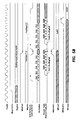
- Figure 3B is a representation of a typical timing diagram illustrating the relationships between the signals shown in Figure 3A;
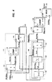
- Figure 4 is a hardware block diagram showing the components used in qualifying sampled signals prior to determination of the background level, in addition to the background determination hardware;
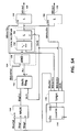
- Figure 5A is another hardware block diagram illustrating the components used for calculation of two relative background values which are used by the image segmentation device of Figure 1;
- Figure 5B is a representation of a typical timing diagram illustrating the relationship between the signals shown in Figure 5A; and
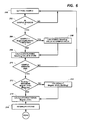
- Figure 6 is a flow diagram illustrating the equivalent steps associated with the operation of the background determination hardware of the present invention.
-
- The following description includes references to slow-scan and fast-scan digital image data, when discussing the orientation of the window coordinates and sampled signals used by the background determination circuitry. For purposes of clarification, data collected along a fast-scan direction is intended to refer to individual pixels located in succession along a raster of image information, while data collected in the slow-scan direction refers to data derived from a common raster position across multiple rasters or scanlines. As an example, slow-scan data would be used to describe signals captured from a plurality of elements along a linear photosensitive array as the array was moved relative to a document. On the other hand, fast-scan data would refer to the sequential signals collected along the length of the linear photosensitive array during a single exposure period, and is also commonly referred to as a raster of data.
- The following description also includes references to video image signals, or pixels, which may be either analog or digital voltage representations of the image, as provided from a suitable source. For example, the image data pixels may be obtained through line by line scanning of an image bearing original by one or more photosensitive element, such as a multiple photosite array of charge coupled devices, commonly referred to as CCD's. Line by line scanning of an image bearing original for the derivation of image data is well known and does not form a part of the present invention. Furthermore, for the purposes of the following description, it will be assumed that the video signals are digital signals that fall within a particular domain of values representing a greyscale, where the lower signal levels generally represent regions of an image having content, as opposed to background regions which will generally be reflected by higher signal levels.
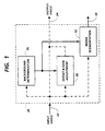
- In the drawings, like reference numerals have been used throughout to designate identical elements. Figure 1 schematically depicts some of the possible components of a digital image processing hardware module, such as might be used in an electrophotographic system for the processing and analysis of a video signal prior to its output.
- Referring now to Figure 1, which illustrates an image processing hardware module incorporating the present invention,
image processing module 20 generally receives video signals online 22, and subsequently processes the video signals to produce an output signal which is transmitted alongline 24. Numerous image processing operations may be carried out withinimage processing module 20, however, in the illustrated example, only two image processing operations are shown in conjunction withbackground determination module 26. The two image processing operation blocks, offset andgain adjustment block 30 andimage segmentation block 32, may be used singularly, in parallel, or may be bypassed completely during processing of the input video. - Typical output from the offset and gain correction block, block 30, is a corrected video signal, possibly utilizing a larger range of the video domain, via gain correction, or a more centralized portion of the domain, via offset correction. In comparison, output from the image segmentation block, via
line 34, is generally in the form of data which is indicative of the imaginal content of certain regions of the image, as defined by the input video signals. As an example, the data output by an image segmentation block designed to detect the presence of high frequency halftoned regions may be used to selectively enable subsequent image processing hardware which might apply a descreening filter (e.g., a low-pass filter) to all image signals indicative of a halftone region. An illustrative example of such an image segmentation block may be found in EP-A-521,662, corresponding to USSN 07/722,568 for "Improved Automatic Image Segmentation". - In addition, the background level determined by the present invention may be further modified to calculate two relative background levels that would be used to classify regions of the image, as described in EP-A-521,662. More specifically, the additional background levels are calculated by multiplying the determined background level by fractional values in order to produce the additional fractional background levels. Once determined, the image segmentation block would utilize these additional levels as thresholds, to identify image signals representing "white" or background pixels or image signals representing grey pixels within the original document. The two fractional background levels are termed, White1 and White2, and are shown as outputs in Figure 5A. Moreover, the fractions used to calculate the White1 and White2 background levels may be programmed, with typical values of 90% for White1 and 82% for White2. These values are used to check or confirm image pixels having values near the background level. For example,
image segmentation block 32 may make a preliminary classification of an image region, and might subsequently confirm the classification by identifying pixels within the region as "white" or background pixels if they have levels greater than White1, or as grey or halftone pixels if they have levels less than White2. Hence, the additional fractional background levels enable a more robust classification method to be used, rather than merely relying on the background level to determine pixels representing background. - Referring now to Figure 2, which illustrates the location of a sample window used by the present invention,
rectangular window 42 defines a region withinimage 44 where pixel signals may be analyzed to determine the background level of the image. The boundaries are defined within the image by the starting location of the window and the length and width of the window. For example,window 42 might have a starting position at position (512, 128), indicated in Figure 2 byreference numeral 46. The starting position will have slow-scan offset of 128 scanlines, distance 50, and a fast-scan offset of 512 pixels,distance 52. The location of the diagonally opposite corner ofwindow 42 is defined by the slow-scan width of the window, and fast-scan length of the window, distances 56 and 58, respectively, both of which are referenced from startingposition 46. In normal operation, the location ofbackground determination window 42 is defined by programming a set of four registers withinbackground detection block 26. Subsequently, during processing of the input video, a set of four counters are used to determine when individual image signals lie within the boundary of the background determination window. - While the size and location of the background determination window is considered to be fully programmable, the present invention has limited the range of possible values, as well as the resolution of the counters, in order to further minimize the cost and number of components necessary to implement the window control or sampling operation. Also, a tradeoff must be made between the size of the sampling window and the accuracy of the background determination value. In other words, image signals generated from documents having a colored background, which are processed using a large background determination window, may show undesirable output or misclassification of image regions, as a result of the delay in determination of an accurate background level, caused by the large window. Moreover, a larger window may result in an overlap of the background sampling region with a non-background region of the image, possibly resulting in a less accurate background level.
- Referring next to Figures 3A and 3B, which detail the digital logic used to make the decision on presence within the background determination window,
Window signal 70 is active high, whenever the image signal passing through the background determination block falls within the boundaries of the window. As illustrated, signal 70 is the product of a NOR operation, block 72, combining five separate signals. The first signal, StartWindow', is produced bycounter 74, and is output whenevercounter 74 reaches a predetermined slow-scan start position value, StartWindVal. As implemented,counter 74 is incremented by a mod-16 pixel clock which produces a single pulse for every sixteen video image signals processed throughimage processing module 20. Because the counter is clocked by a clock that is essentially one-sixteenth the resolution of the pixel clock, PixClk, the resolution of the counter is also reduced, resulting in the need to adjust the value of StartWindVal by dividing by sixteen. For instance, window startposition 46 of Figure 2 was described as being 512 pixels from the start of the scanline. If this were the case, the StartWindVal would be one-sixteenth of that distance, or thirty-two. Upon reaching the StartWindVal value, counter 74 outputs an active-low signal on the carry-out output, StartWindow'line, and disables further counting until reaching the end of a scanline of image signals. At that point, the counter will be reset and reloaded to once again begin counting to determine the offset of the starting position for the window. - In a manner similar to that described for
counter 74,counter 78 is used to track the end of the background determination window, in the fast-scan direction.Counter 78 outputs an active-low carry-out signal, EndWindow', whenever it has reached the EndWindVal value. The actual value of EndWindVal is one-sixteenth the value of the window length, as illustrated bydistance 58 of Figure 2, for the same reasons previously described with respect to counter 74. More importantly,counter 78 is disabled, meaning that it is not incremented, until carry-out ofcounter 74 is active. In other words, counter 78 begins counting aftercounter 74 has stopped counting, thereby establishing the length of the window with reference to the fast-scan start position. The output ofcounter 78, EndWindow', is used in an inverted fashion as an input to NOR block 72 and toOR-gate 80. - While
counters Counter 80 is preprogrammed with a value, WinOffVal, representative of the the slow-scan offset distance, distance 50 of Figure 2, before processing begins. After initiating the processing of the image signals,counter 80 is incremented each time a scanline of image signals has been processed. When the preprogrammed number of scanlines have been processed, the WinOffset output value will transition to an active-high state to indicate that the beginning of the window has been reached along the slow-scan direction. As in the fast-scan window counters, the output ofcounter 80, WinOffset, will be used to enable the subsequent operation of slow-scan width counter 82. -
Counter 82, the counter which tracks the end of the background determination window in the slow-scan direction, increments once per scanline until a value equal to the slow-scan length of the window, SSWinVal, has been reached. At that time, counter 82 will output an active-high signal on the carry-out line, CO. The signal on the CO line is subsequently passed to AND-gate 84 along with the LineSync' signal, an active-high signal that indicates when a raster of image signals is being processed. More importantly, the output ofAND-gate 84 is passed to flip-flop 86 to produce output SSWindow, which is a pulsed signal used by the windowing hardware of Figure 3A and averaging hardware of Figure 4, to signal when the background level has been determined, and is valid. An active-low output from flip-flop 86, SSWind', is used as the second input to OR-gate 80, the output of which controls the enable line of flip-flop 90, thereby causing the output of flip-flop 90, BkgLtchEn, to transition to an active level at the beginning of the first scanline following the end of the background determination window. - As the signals represented in Figure 3B illustrate, sampling regions, S1, S2, S3 are identified by the Window signal which is output from
NOR-gate 72. Also, the timing diagram clearly indicates the slow-scan offset, generally indicated byreference arrow 102, and the fast-scan offsets for each scanline,arrows - Referring now to Figure 4, which illustrates the logic blocks used to verify the video image signals and calculate the running average of the signals,
line 114 supplies the signals to the circuitry, where they are temporarily stored atlatch 116. Aslatch 116 is enabled by the Window signal, no data is latched unless the Window signal of Figures 3A and 3B is active, thereby causing the hardware to operate only on the image signals contained within the window boundaries. Assuming that the image signal lies within the background determination window, the latched value, WinVid, is compared against a threshold value, BkgExclude, atcomparator 118. If the value of WinVid is below the value of BkgExclude, then the signal is determined to be indicative of a marked region of the image, or in other words, a non-background signal which should be excluded from the running average of the background region. The output ofcomparator 118 determines whether the Video signal will be used for subsequent calculation by controlling the select line ofMUX 120.MUX 120 selects the incoming video signal, Video, or the accumulated running average, AccAvg, and outputs the value, Videoln, online 122. - Subsequently,
arithmetic processing circuitry 126 processes the signal online 122 in accordance with equation (a): - AccAvg is the running average for the background level,
- Videoln is the value of the incoming video signal, and
- X is a constant indicative of the relative weighting between the running average and the incoming video signal. In the present implementation, X is assumed to be seven-eighths (7/8), resulting, not only in a minimization of the contribution of each video signal to the running average, but, also making the hardware implementation less complex and less expensive. It should be understood, however, that alternative weightings for the running average and incoming video signals have been contemplated and may be employed by the present invention. Substituting seven-eighths for the value of X in equation (a), and simplifying the equation results in equation (b).
-
- As implemented in
arithmetic circuit 126 using signed two's complement arithmetic, subtractor/divider 128 subtracts the AccAvg value from the Videoln value and subsequently divides the result by eight by dropping the three least significant bits of the result. Once again, to simplify the hardware implementation, subtractor/divider 128 is actually an adder that operates on signed two's compliment values, where the running average, AccAvg, is an eight-bit number having a sign-bit (ninth-bit) which is set, and Videoln is an eight-bit number having a zeroed sign-bit. Next, the six-bit (five significant bits plus sign-bit) result from subtractor/divider 128, Sub, is passed to summation block 130 where it is added to the AccAvg operand. The resultant summation signal, Sum, is output from summation block 130 and is stored inlatch 132, making it available for subsequent use in calculating the running average as previously described. As shown,latch 132 is enabled by the Window signal, thereby continuously latching the resultant running average, Sum, while the video signals are within the sample window. The logic components ofverification circuit 112 andarithmetic circuit 126 are generally operative only when the Window signal is active, thereby limiting the image signal samples processed to those occurring within the boundaries ofbackground determination window 42 of Figure 2. After completing the sampling and calculation of the background level, the AccAvg value is advanced and stored inlatch 134. - Subsequent to determining the final running average and storing it at
latch 134, the value of AccAvg is compared against a lower threshold value atcomparator 138. This test is implemented to assure that the value calculated is within a reasonable range of values, and to prevent deleterious effects that might be caused by a very low background level. Hence, the output ofcomparator 138 is used to select between the actual running average, AccAvg, or a default background level, DefBkg, atMUX 140. The output fromMUX 140 being the background level which will be passed to the remaining digital logic circuitry for determination of the various background percentages, as illustrated in Figures 5A and 5B. - Referring now to Figures 5A and 5B, which illustrate the digital logic operations that are used to determine the two additional background levels, White1 and White2, the BkGndVal signal output from
MUX 140 of Figure 4 is subsequently used to determine the additional background values that are output onlines MUX 150. The value to be used to produce the fractional representation of the background value, White1 or White2, is determined via the MuxSel line, which first enables the processing of fBkg1 and then fBkg2, as illustrated by the transition of MuxSel from a high to a low signal level in Figure 5B. Once selected, the 5-bit fractional value, BkgPct, is output fromMUX 150 toshift register 152, where the the parallel data is serialized into single bits, fract0 - fract4, and passed sequentially toserial multiplier block 154. -
Serial multiplier block 154, the operation of which is illustrated by the timing diagram of Figure 5B, first receives the background level signal, BkGndVal, at AND block 156, where the it is ANDed with one of the sequential bits of the fractional value being output fromshift register 152. The result of the AND operation is then passed to summation block 158 where it is added to a previous result which had been stored inlatch 162. The following example will illustrate the steps of the serial multiply operation carried out byserial multiplier 154. - Assuming,
- BkGndVal =
- 240, or (1111000b); and
- BkgPct =
- 15/32, or (01111b); then
- Both the MuxSel and Shift lines are controlled by
digital logic block 176, generally implemented as a decoder which, in response to output from clock-cycle counter 174, controls the sequencing of the logic components used to produce the output values White1 and White2. In addition,logic block 176 also provides the latch enable signals, White1En and White2En output to latches 164 and 166, respectively, to signal those latches whenlatch 162 contains a valid fractional background value. As illustrated by the above example and the timing diagram of Figure 5B, the five cycles of the serial multiplier are executed, as indicated by the Multiplier and Accum/Sum signals, before the latch enable signals are raised. While the present embodiment is limited to a 5-bit fraction, a larger fraction may be used, however, this would obviously require additional steps in the serial multiplication process. Subsequently, the White1 and White2 fractional background levels may be used byimage segmentation block 32 of Figure 1 for classification of individual image pixels as previously described. - Having described the digital logic elements used to implement one embodiment of the background determination apparatus of the present invention, the operational steps of the apparatus will now be described with respect to the flowchart of Figure 6. In a preferred embodiment, the background determination apparatus is used to detect and output the magnitude of the signals within the background regions of an image while the image is being generated by a scanning device. In order to provide a background level indication, or background signal, the background determination apparatus must use a "substitute" or default level until sufficient image context has been analyzed to determine an actual background level. Accordingly, the present invention allows for maximum flexibility in determining the default value, DefBkg, by providing a register that may be programmed with the desired value. Similarly, the sampling window data (StartWinVal, WinOffVal, EndWinVal, SSWinVal), the background fractions (fBkg1, fBkg2) and the thresholds (BkgExclude, BkgLow) may be programmed by writing a values to a registers in memory, using any suitable microprocessor or microcontroller. Once the default background level, the thresholds, the background fractions, and the window coordinates are programmed, the apparatus is ready to begin receiving image signals for determination of the background video level.
- As previously stated, the background determination apparatus initially outputs the default background level, DefBkg, until the image signals lying within the sample window have been processed. The processing operation that occurs during the interim period before the actual background level is determined, is illustrated in Figure 6. The recurring process begins at
step 200, where the image signal is passed to the background determination apparatus, as represented by the video signal in Figure 1. Once the pixel, or video signal is received, a determination is made atstep 202, as to whether the sampled signal is from within the region defined by the sampling window. This step utilizes the Window signal, Figure 4, to make that determination. If not, processing continues atstep 200, where the system waits for the next sample. If, however, the sample was within the window, it is first compared against a black threshold level, BkgExclude, atstep 204 to determine if it should be included in the running average. If the sample is greater than BkgExclude, then it is determined to be reflective of a possible background value and will be used in the calculation of the new running average atstep 206. However, if the sample was less than BkgExclude, it would not be used, and the previous running average value would be substituted for the sampled signal value,step 208. In alternative embodiments, it may also be possible to simply exclude the sampled signal when it was below the BkgExclude level, or to substitute other alternate values, possibly even programmable constants such as BkgExclude. - As previously shown with respect to Figure 4, the running average is calculated using the arithmetic processing circuitry, 126 of Figure 4. Once the end of the sample window has been detected at
step 210, and as indicated by the SSWlndow signal pulse, processing would continue atstep 212. Otherwise, the running average is calculated for the next pixel sample found within the sample window by continuing atstep 200. Atstep 212, the running average of the background level, AccAvg, is compared against the minimum background level, BkgLow, to determine if the background level determined by the hardware is valid. If greater than the minimum background level, then the actual background level, AccAvg, is used to calculate the the fractional background levels atstep 214. Otherwise, the default background level,step 216, is passed toserial multiplier 154 of Figure 5A for calculation of the fractional background levels. Once the pair of fractional background levels has been determined,step 214, the background determination apparatus interruptsimage segmentation device 32,step 218, to indicate that valid fractional background levels have been generated. Subsequently, the fractional background values inlatches 164 and 166 (Figure 5) would be passed to the image segmentation device. Moreover, the background level determined for the sample window is also made available for retrieval by the system. Finally, once the background level has been determined, the apparatus remains in an idle state until being reset by a signal indicating the end of the image has been reached. - In recapitulation, the present invention implements a background determination or detection process using digital logic components. The invention enables the determination of the background level of an image during image input, thereby enabling the immediate use of one or more background levels for analysis and processing of the image signals. Moreover, the present invention includes programmable features and validation logic to make the device flexible, while assuring that the apparatus produces a highly reliable background level result.

Claims (9)
- An apparatus for determining the background level of an image represented by a plurality of video signals, said video signals (Video) representing both the content regions of the image and the background regions of the image, comprising:sampling window means (72-90) for generating a window signal (70) to identify a background determination window as a selected region of the video signals inside the background determination window during a single pass scanning operation;video signal qualification means (112), operating on the selected region, for determining those sampled video signals which are non-representative of the background level, said video signal qualification means eliminating only the non-representative video signals;means (126), coupled to said video signal qualification means, for calculating a running average background level (AccAvg) as a function of the level of the non-eliminated sampled video signals (Videoln);means (234,138,140) for changing between a default background value (DefBkg) and the running average background level (AccAvg) as an output background level (BkGndVal) during processing of the selected region of the video signals inside the background determination window.
- The image processing apparatus of claim 1 further including means (150-176) for computing at least one additional background level (White 1, White 2) for use by the image processing apparatus, with the additional background level being a fractional portion of the background level (BkGndVal).
- The image processing apparatus of claim 2 wherein the computing means (150-176) comprises:first storing means for storing at least one digital fraction (fBkg1, fBkg2); anda serial multiplier (154), coupled to said first storing means, for sequentially multiplying the stored digital fraction by the background level to produce the additional background level.
- The image processing apparatus of claim 3 wherein the computing means further comprises:second storing means (164,166) for storing at least one additional background level (White 1, White 2) produced by the serial multiplier; andlogic control means (176) for controlling the selection of the first storing means and the second storing means (164,166) in conjunction with the sequencing of the serial multiplier (154), so as to enable the computation of at least two additional background levels.
- The image processing apparatus of claim 2, 3 or 4 including means (32), responsive to the additional background level (White 1, White 2), for delimiting at least two distinct ranges of signal levels to be used for classification of video signals (Video) having levels falling within the ranges.
- The image processing apparatus of any of the preceding claims wherein the window means includes:means (74,78) for identifying a selected region (42) within the image; andcontrol means (70,72,78-90), responsive to said sample region identifying means, for indicating when a video signal received by the background determination apparatus is within the sample region.
- A method of determining the level of the background region of an image represented by a plurality of video signals (Video), during the processing of the video signals in a single pass scanning operation, comprising the steps of:receiving (200) the video signals as a stream of sequential signals generated in a single pass scanning operation;sampling (202) a selected portion of the video signals received to identify signals within a background determination window;eliminating (204-208) only sampled video signals within the background determination window that are non-representative of the level of the background region; andoutputting a default background level (DefBkg) while calculating (212-216) a running average background level (AccAvg) as a function of the non-eliminated sampled video signals within the background determination window, so as to continuously output a background level during the single pass scanning operation.
- The method of claim 7 further including the step (150-176) of computing at lease one additional background magnitude (White 1, White 2) with the additional background magnitude being a function, for example a fractional portion of the background magnitude (BkGndVal).
- The method of claim 7 or 8 including the steps of:storing coordinates, of a window region; andgenerating in response to the stored window coordinates, a window signal associated with the video signal, with the level of the window signal being indicative of whether the video signal is within the window region.
Applications Claiming Priority (2)
| Application Number | Priority Date | Filing Date | Title |
|---|---|---|---|
| US811853 | 1991-12-23 | ||
| US07/811,853 US5282061A (en) | 1991-12-23 | 1991-12-23 | Programmable apparatus for determining document background level |
Publications (3)
| Publication Number | Publication Date |
|---|---|
| EP0549255A2 EP0549255A2 (en) | 1993-06-30 |
| EP0549255A3 EP0549255A3 (en) | 1994-04-06 |
| EP0549255B1 true EP0549255B1 (en) | 1999-04-14 |
Family
ID=25207774
Family Applications (1)
| Application Number | Title | Priority Date | Filing Date |
|---|---|---|---|
| EP92311499A Expired - Lifetime EP0549255B1 (en) | 1991-12-23 | 1992-12-16 | Method and programmable apparatus for determining document background level |
Country Status (4)
| Country | Link |
|---|---|
| US (1) | US5282061A (en) |
| EP (1) | EP0549255B1 (en) |
| JP (1) | JP3254272B2 (en) |
| DE (1) | DE69228921T2 (en) |
Families Citing this family (40)
| Publication number | Priority date | Publication date | Assignee | Title |
|---|---|---|---|---|
| WO1989001650A1 (en) * | 1987-08-10 | 1989-02-23 | Idemitsu Petrochemical Company Limited | Durable patterning member |
| US5537491A (en) * | 1993-11-24 | 1996-07-16 | Xerox Corporation | Analyzing an image or other data to obtain a stable number of groups |
| US5850298A (en) * | 1994-03-22 | 1998-12-15 | Ricoh Company, Ltd. | Image processing device eliminating background noise |
| US5796877A (en) * | 1995-12-11 | 1998-08-18 | Xerox Corporation | Method and apparatus for automatically fitting an input image to the size of the output document |
| US5956468A (en) * | 1996-07-12 | 1999-09-21 | Seiko Epson Corporation | Document segmentation system |
| US5936684A (en) * | 1996-10-29 | 1999-08-10 | Seiko Epson Corporation | Image processing method and image processing apparatus |
| US6038340A (en) * | 1996-11-08 | 2000-03-14 | Seiko Epson Corporation | System and method for detecting the black and white points of a color image |
| US5835628A (en) * | 1996-11-21 | 1998-11-10 | Xerox Corporation | Method and system for generating histograms from a scanned image |
| US5848183A (en) * | 1996-11-21 | 1998-12-08 | Xerox Corporation | System and method for generating and utilizing histogram data from a scanned image |
| US5881166A (en) * | 1996-11-21 | 1999-03-09 | Xerox Corporation | Method and system for generating a histogram of a scanned image |
| US5751848A (en) * | 1996-11-21 | 1998-05-12 | Xerox Corporation | System and method for generating and utilizing histogram data from a scanned image |
| JP3114668B2 (en) * | 1997-10-03 | 2000-12-04 | 日本電気株式会社 | Object detection / background removal method, apparatus, and recording medium recording program |
| US6198835B1 (en) * | 1998-01-08 | 2001-03-06 | Xerox Corporation | Image input device and method for providing scanning artifact detection |
| US6122393A (en) * | 1998-01-08 | 2000-09-19 | Xerox Corporation | Image input device and method for providing scanning artifact detection |
| US6246781B1 (en) * | 1998-01-08 | 2001-06-12 | Xerox Corporation | Image input device and method for providing scanning artifact detection |
| US6323957B1 (en) * | 1998-06-01 | 2001-11-27 | Xerox Corporation | Background noise removal for a low-cost digital color copier |
| US6222642B1 (en) | 1998-08-10 | 2001-04-24 | Xerox Corporation | System and method for eliminating background pixels from a scanned image |
| US7912295B1 (en) * | 1999-09-28 | 2011-03-22 | Transpacific Optics Llc | Method for auto-cropping a scanned image |
| US6618171B1 (en) | 2000-02-25 | 2003-09-09 | Xerox Corporation | Black point adjustment based on image background |
| DE10026700B4 (en) * | 2000-05-30 | 2008-03-27 | Transpacific Optics LLC, Wilmington | Method of automatically trimming a scanned image |
| US6621599B1 (en) * | 2000-06-14 | 2003-09-16 | Xerox Corporation | Auto-width detection using backing image |
| JP4085580B2 (en) * | 2001-02-20 | 2008-05-14 | 富士ゼロックス株式会社 | Image processing device |
| US7057767B2 (en) * | 2001-03-06 | 2006-06-06 | Hewlett-Packard Development Company, L.P. | Automatic background removal method and system |
| US20050265600A1 (en) * | 2004-06-01 | 2005-12-01 | Xerox Corporation | Systems and methods for adjusting pixel classification using background detection |
| US10687166B2 (en) | 2004-09-30 | 2020-06-16 | Uber Technologies, Inc. | Obtaining user assistance |
| US10445799B2 (en) | 2004-09-30 | 2019-10-15 | Uber Technologies, Inc. | Supply-chain side assistance |
| US9747579B2 (en) | 2004-09-30 | 2017-08-29 | The Invention Science Fund I, Llc | Enhanced user assistance |
| US10514816B2 (en) | 2004-12-01 | 2019-12-24 | Uber Technologies, Inc. | Enhanced user assistance |
| US20130238991A1 (en) * | 2004-10-27 | 2013-09-12 | Searete Llc | Enhanced Contextual User Assistance |
| US7574038B1 (en) | 2005-03-31 | 2009-08-11 | Adobe Systems Incorporated | Method and apparatus for determining the background of an image sequence |
| US7555172B2 (en) * | 2005-10-31 | 2009-06-30 | Xerox Corporation | Dynamic range detection and adjustment |
| US8358976B2 (en) | 2006-03-24 | 2013-01-22 | The Invention Science Fund I, Llc | Wireless device with an aggregate user interface for controlling other devices |
| TWI360353B (en) * | 2008-06-11 | 2012-03-11 | Vatics Inc | Method for auto-white-balance control |
| US8111918B2 (en) * | 2008-10-20 | 2012-02-07 | Xerox Corporation | Segmentation for three-layer mixed raster content images |
| US8933927B2 (en) * | 2010-09-02 | 2015-01-13 | Samsung Electronics Co., Ltd. | Display system with image conversion mechanism and method of operation thereof |
| US9483744B2 (en) | 2014-05-06 | 2016-11-01 | Elwha Llc | Real-time carpooling coordinating systems and methods |
| US10458801B2 (en) | 2014-05-06 | 2019-10-29 | Uber Technologies, Inc. | Systems and methods for travel planning that calls for at least one transportation vehicle unit |
| US9552559B2 (en) | 2014-05-06 | 2017-01-24 | Elwha Llc | System and methods for verifying that one or more directives that direct transport of a second end user does not conflict with one or more obligations to transport a first end user |
| US11100434B2 (en) | 2014-05-06 | 2021-08-24 | Uber Technologies, Inc. | Real-time carpooling coordinating system and methods |
| WO2017158483A1 (en) | 2016-03-14 | 2017-09-21 | Insightness Ag | A vision sensor, a method of vision sensing, and a depth sensor assembly |
Family Cites Families (13)
| Publication number | Priority date | Publication date | Assignee | Title |
|---|---|---|---|---|
| US4339745A (en) * | 1980-05-14 | 1982-07-13 | General Electric Company | Optical character recognition |
| US4442544A (en) * | 1981-07-09 | 1984-04-10 | Xerox Corporation | Adaptive thresholder |
| US4593325A (en) * | 1984-08-20 | 1986-06-03 | The Mead Corporation | Adaptive threshold document duplication |
| US5065257A (en) * | 1985-03-20 | 1991-11-12 | Canon Kabushiki Kaisha | Image processing apparatus with means for compensating for dust., etc., on an original |
| DE3623294A1 (en) * | 1985-07-10 | 1987-02-05 | Fuji Electric Co Ltd | SYSTEM FOR BINARY CODING AN IMAGE |
| JPS6269384A (en) * | 1985-09-21 | 1987-03-30 | Nachi Fujikoshi Corp | Automatic setting method for binary coding level |
| FR2602387B1 (en) * | 1986-07-30 | 1988-10-21 | Trt Telecom Radio Electr | METHOD FOR AUTOMATICALLY EXTRACTING A CONTRAST OBJECT FROM A DIGITAL IMAGE |
| US4827253A (en) * | 1987-05-18 | 1989-05-02 | Dubner Computer Systems, Inc. | Video compositing using a software linear keyer |
| US4796219A (en) * | 1987-06-01 | 1989-01-03 | Motorola, Inc. | Serial two's complement multiplier |
| US4868670A (en) * | 1987-07-24 | 1989-09-19 | Eastman Kodak Company | Apparatus and method for improving the compressibility of an enhanced image through use of a momentarily varying threshold level |
| US4811115A (en) * | 1987-10-16 | 1989-03-07 | Xerox Corporation | Image processing apparatus using approximate auto correlation function to detect the frequency of half-tone image data |
| IT1219119B (en) * | 1988-03-18 | 1990-05-03 | Olivetti & Co Spa | AUTOMATIC THRESHOLD ADJUSTMENT CIRCUIT OF A READING SIGNAL FOR A DIGITAL IMAGE SCANNING DEVICE |
| JPH02196565A (en) * | 1989-01-25 | 1990-08-03 | Eastman Kodatsuku Japan Kk | Picture binarizing system |
-
1991
- 1991-12-23 US US07/811,853 patent/US5282061A/en not_active Expired - Lifetime
-
1992
- 1992-12-16 EP EP92311499A patent/EP0549255B1/en not_active Expired - Lifetime
- 1992-12-16 DE DE69228921T patent/DE69228921T2/en not_active Expired - Fee Related
- 1992-12-18 JP JP33911392A patent/JP3254272B2/en not_active Expired - Fee Related
Also Published As
| Publication number | Publication date |
|---|---|
| JP3254272B2 (en) | 2002-02-04 |
| EP0549255A3 (en) | 1994-04-06 |
| DE69228921T2 (en) | 1999-10-07 |
| US5282061A (en) | 1994-01-25 |
| JPH05276365A (en) | 1993-10-22 |
| EP0549255A2 (en) | 1993-06-30 |
| DE69228921D1 (en) | 1999-05-20 |
Similar Documents
| Publication | Publication Date | Title |
|---|---|---|
| EP0549255B1 (en) | Method and programmable apparatus for determining document background level | |
| EP0521662B1 (en) | Improved automatic image segmentation | |
| EP1215884B1 (en) | Automatic background detection of scanned documents | |
| US4856075A (en) | Image discrimination | |
| US4811115A (en) | Image processing apparatus using approximate auto correlation function to detect the frequency of half-tone image data | |
| EP1330111B1 (en) | Automatic image quality evaluation and correction technique | |
| EP0331687B1 (en) | Apparatus and methods for locating edges and document boundaries in video scan lines | |
| US4442544A (en) | Adaptive thresholder | |
| EP0371055B1 (en) | Apparatus for enhancing and thresholding scanned microfilm images and methods for use therein | |
| JP3046493B2 (en) | Image processing device | |
| JPH06103923B2 (en) | Image processing method and apparatus | |
| US4817174A (en) | Image processing apparatus | |
| US5831748A (en) | Image processor | |
| US5086486A (en) | Apparatus for reading a document and processing the image | |
| US5086485A (en) | Method and apparatus for dynamically setting a background level | |
| US7161626B1 (en) | Image reading apparatus | |
| EP0236594A1 (en) | Method of and device for recognizing half-tone image information | |
| JP3262326B2 (en) | Image processing apparatus and image processing method | |
| JPH0787313A (en) | System and device for image processing | |
| US5299030A (en) | Image data processing method and apparatus with mixture of simple binarization and psuedo intermediate tone | |
| US5228099A (en) | Apparatus for reading a document and processing the image | |
| EP0869662B1 (en) | Image binarization system | |
| JP3373876B2 (en) | Image processing device | |
| US6128408A (en) | Method for augmenting sum-of-laplacians in light and dark areas of halftone field to maintain reliable segmentation | |
| JPH05219370A (en) | Picture processing unit |
Legal Events
| Date | Code | Title | Description |
|---|---|---|---|
| PUAI | Public reference made under article 153(3) epc to a published international application that has entered the european phase |
Free format text: ORIGINAL CODE: 0009012 |
|
| AK | Designated contracting states |
Kind code of ref document: A2 Designated state(s): DE FR GB |
|
| PUAL | Search report despatched |
Free format text: ORIGINAL CODE: 0009013 |
|
| AK | Designated contracting states |
Kind code of ref document: A3 Designated state(s): DE FR GB |
|
| 17P | Request for examination filed |
Effective date: 19941006 |
|
| 17Q | First examination report despatched |
Effective date: 19960123 |
|
| GRAG | Despatch of communication of intention to grant |
Free format text: ORIGINAL CODE: EPIDOS AGRA |
|
| GRAG | Despatch of communication of intention to grant |
Free format text: ORIGINAL CODE: EPIDOS AGRA |
|
| GRAH | Despatch of communication of intention to grant a patent |
Free format text: ORIGINAL CODE: EPIDOS IGRA |
|
| GRAH | Despatch of communication of intention to grant a patent |
Free format text: ORIGINAL CODE: EPIDOS IGRA |
|
| GRAA | (expected) grant |
Free format text: ORIGINAL CODE: 0009210 |
|
| AK | Designated contracting states |
Kind code of ref document: B1 Designated state(s): DE FR GB |
|
| REF | Corresponds to: |
Ref document number: 69228921 Country of ref document: DE Date of ref document: 19990520 |
|
| ET | Fr: translation filed | ||
| PLBE | No opposition filed within time limit |
Free format text: ORIGINAL CODE: 0009261 |
|
| STAA | Information on the status of an ep patent application or granted ep patent |
Free format text: STATUS: NO OPPOSITION FILED WITHIN TIME LIMIT |
|
| 26N | No opposition filed | ||
| REG | Reference to a national code |
Ref country code: GB Ref legal event code: IF02 |
|
| PGFP | Annual fee paid to national office [announced via postgrant information from national office to epo] |
Ref country code: FR Payment date: 20081212 Year of fee payment: 17 |
|
| PGFP | Annual fee paid to national office [announced via postgrant information from national office to epo] |
Ref country code: DE Payment date: 20081211 Year of fee payment: 17 |
|
| PGFP | Annual fee paid to national office [announced via postgrant information from national office to epo] |
Ref country code: GB Payment date: 20081210 Year of fee payment: 17 |
|
| GBPC | Gb: european patent ceased through non-payment of renewal fee |
Effective date: 20091216 |
|
| REG | Reference to a national code |
Ref country code: FR Ref legal event code: ST Effective date: 20100831 |
|
| PG25 | Lapsed in a contracting state [announced via postgrant information from national office to epo] |
Ref country code: FR Free format text: LAPSE BECAUSE OF NON-PAYMENT OF DUE FEES Effective date: 20091231 |
|
| PG25 | Lapsed in a contracting state [announced via postgrant information from national office to epo] |
Ref country code: DE Free format text: LAPSE BECAUSE OF NON-PAYMENT OF DUE FEES Effective date: 20100701 |
|
| PG25 | Lapsed in a contracting state [announced via postgrant information from national office to epo] |
Ref country code: GB Free format text: LAPSE BECAUSE OF NON-PAYMENT OF DUE FEES Effective date: 20091216 |