EP0549950A1 - Arrangement for locking against inserting of batteries which are not in regular states of charge into electric appliances and/or charges - Google Patents
Arrangement for locking against inserting of batteries which are not in regular states of charge into electric appliances and/or charges Download PDFInfo
- Publication number
- EP0549950A1 EP0549950A1 EP92121354A EP92121354A EP0549950A1 EP 0549950 A1 EP0549950 A1 EP 0549950A1 EP 92121354 A EP92121354 A EP 92121354A EP 92121354 A EP92121354 A EP 92121354A EP 0549950 A1 EP0549950 A1 EP 0549950A1
- Authority
- EP
- European Patent Office
- Prior art keywords
- battery
- charge
- charger
- consumer
- accumulators
- Prior art date
- Legal status (The legal status is an assumption and is not a legal conclusion. Google has not performed a legal analysis and makes no representation as to the accuracy of the status listed.)
- Withdrawn
Links
Images
Classifications
-
- H—ELECTRICITY
- H01—ELECTRIC ELEMENTS
- H01M—PROCESSES OR MEANS, e.g. BATTERIES, FOR THE DIRECT CONVERSION OF CHEMICAL ENERGY INTO ELECTRICAL ENERGY
- H01M50/00—Constructional details or processes of manufacture of the non-active parts of electrochemical cells other than fuel cells, e.g. hybrid cells
- H01M50/20—Mountings; Secondary casings or frames; Racks, modules or packs; Suspension devices; Shock absorbers; Transport or carrying devices; Holders
- H01M50/247—Mountings; Secondary casings or frames; Racks, modules or packs; Suspension devices; Shock absorbers; Transport or carrying devices; Holders specially adapted for portable devices, e.g. mobile phones, computers, hand tools or pacemakers
-
- H—ELECTRICITY
- H01—ELECTRIC ELEMENTS
- H01M—PROCESSES OR MEANS, e.g. BATTERIES, FOR THE DIRECT CONVERSION OF CHEMICAL ENERGY INTO ELECTRICAL ENERGY
- H01M10/00—Secondary cells; Manufacture thereof
- H01M10/42—Methods or arrangements for servicing or maintenance of secondary cells or secondary half-cells
- H01M10/48—Accumulators combined with arrangements for measuring, testing or indicating the condition of cells, e.g. the level or density of the electrolyte
-
- H—ELECTRICITY
- H01—ELECTRIC ELEMENTS
- H01M—PROCESSES OR MEANS, e.g. BATTERIES, FOR THE DIRECT CONVERSION OF CHEMICAL ENERGY INTO ELECTRICAL ENERGY
- H01M50/00—Constructional details or processes of manufacture of the non-active parts of electrochemical cells other than fuel cells, e.g. hybrid cells
- H01M50/50—Current conducting connections for cells or batteries
- H01M50/572—Means for preventing undesired use or discharge
- H01M50/584—Means for preventing undesired use or discharge for preventing incorrect connections inside or outside the batteries
- H01M50/588—Means for preventing undesired use or discharge for preventing incorrect connections inside or outside the batteries outside the batteries, e.g. incorrect connections of terminals or busbars
-
- H—ELECTRICITY
- H02—GENERATION; CONVERSION OR DISTRIBUTION OF ELECTRIC POWER
- H02J—CIRCUIT ARRANGEMENTS OR SYSTEMS FOR SUPPLYING OR DISTRIBUTING ELECTRIC POWER; SYSTEMS FOR STORING ELECTRIC ENERGY
- H02J7/00—Circuit arrangements for charging or depolarising batteries or for supplying loads from batteries
- H02J7/0029—Circuit arrangements for charging or depolarising batteries or for supplying loads from batteries with safety or protection devices or circuits
- H02J7/0031—Circuit arrangements for charging or depolarising batteries or for supplying loads from batteries with safety or protection devices or circuits using battery or load disconnect circuits
-
- Y—GENERAL TAGGING OF NEW TECHNOLOGICAL DEVELOPMENTS; GENERAL TAGGING OF CROSS-SECTIONAL TECHNOLOGIES SPANNING OVER SEVERAL SECTIONS OF THE IPC; TECHNICAL SUBJECTS COVERED BY FORMER USPC CROSS-REFERENCE ART COLLECTIONS [XRACs] AND DIGESTS
- Y02—TECHNOLOGIES OR APPLICATIONS FOR MITIGATION OR ADAPTATION AGAINST CLIMATE CHANGE
- Y02E—REDUCTION OF GREENHOUSE GAS [GHG] EMISSIONS, RELATED TO ENERGY GENERATION, TRANSMISSION OR DISTRIBUTION
- Y02E60/00—Enabling technologies; Technologies with a potential or indirect contribution to GHG emissions mitigation
- Y02E60/10—Energy storage using batteries
Abstract
Description
Die Erfindung betrifft eine Einrichtung zum Sperren gegen Einlegen von Akkumulatoren, die sich nicht in bestimmungsgemäßen Ladezuständen befinden, in elektrische Verbraucher-Geräte und/oder Ladegeräte gemäß dem Oberbegriff des Anspruchs 1.The invention relates to a device for blocking against insertion of accumulators, which are not in the intended charge states, into electrical consumer devices and / or chargers according to the preamble of
Zum Betrieb von elektrischen Geräten mit veränderlichen Einsatzorten, wie Filmkameras, Videokameras, tragbaren Rundfunk- und Fernsehgeräten, Messgeräten usw., hier kurz Verbraucher-Geräte (VG) genannt, werden meistens wiederaufladbare NiCd-Akkus eingesetzt. In den wenigsten Fällen werden auch sogenannte Batteriepacks verwendet. Bei Verwendung beider Energiequellen kommt es, vornehmlich im Feldbetrieb, zu Ärgernissen, wenn der Energievorrat nicht ausreicht. Speziell beim Einsatz von NiCd-Akkus tritt darüber hinaus noch ein zweiter gravierender Nachteil auf, nämlich der sogenannte Memory-Effekt, welcher dazu führt, daß die volle Kapazität des Akkus nicht mehr zur Verfügung steht, also nicht mehr nutzbar ist. Zu vermeiden ist der Memory-Effekt nur, wenn die Akkus immer einen vollen Lade- und Entladezyklus durchmachen. Das bedeutet, daß sie immer vor dem Einsatz in das VG voll geladen und vor dem Laden im Ladegerät (LG) immer erst vollständig entladen werden müssen. Dies jedoch zu realisieren, erfordert fast schon eine buchführende Maßnahme wie Zeiterfassung, Betriebsstundennachweis, usw. Das wiederum macht den Betrieb der Geräte benutzerunfreundlich, weil der Benutzer eine zu große Aufmerksamkeit der Spannungsversorgung seines Gerätes widmen muß.Rechargeable NiCd batteries are mostly used to operate electrical devices with variable locations, such as film cameras, video cameras, portable radio and television sets, measuring devices, etc., here briefly called consumer devices (VG). So-called battery packs are rarely used. When both energy sources are used, there are annoyances, especially in field operation, if the energy supply is insufficient. Especially when using NiCd batteries, there is also a second serious disadvantage, namely the so-called memory effect, which means that the full capacity of the battery is no longer available stands, that is no longer usable. The memory effect can only be avoided if the batteries always go through a full charge and discharge cycle. This means that they must always be fully charged before use in the VG and must always be fully discharged before charging in the charger (LG). Realizing this, however, almost requires an accounting measure such as time recording, operating hours, etc. This in turn makes the operation of the devices user-unfriendly, because the user has to pay too much attention to the voltage supply of his device.
Aufgabe der Erfindung ist es daher, die Spannungsversorgung von Geräten mit veränderlichen Einsatzorten so zu gestalten, daß sich eine in Bezug auf die bestimmungsgemäßen Ladezustände der Energiequellen richtige und einfache Benutzung der Energiequellen ergibt.The object of the invention is therefore to design the voltage supply of devices with variable locations so that correct and simple use of the energy sources results in relation to the intended charging states of the energy sources.
Diese Aufgabe wird durch die im Anspruch 1 angegebenen Merkmale gelöst. Die erfindungsgemäße Einrichtung weist den Vorteil auf, daß durch Mitbenutzung ohnehin in elektrischen Geräten oder Ladegeräten vorhandener Komponenten, wie Steuereinrichtung, Messeinrichtung, Anzeigeeinrichtung und elektromechanische Sperren, zuverlässig das Einlegen von Akkumulatoren, die sich nicht in bestimmungsgemäßen Ladezuständen befinden, verhindert wird. Dabei wird der zusätzliche Schaltungsaufwand von der programmtechnischen Lösung der Steuereinrichtung bestimmt.This object is achieved by the features specified in
Die zur Realisierung der Einrichtung benötigten Einzelkomponenten sind größtenteils bekannt. Erst durch die erfindungsgemäße Kombination dieser Komponenten kommt die gewünschte Einrichtung zustande.Most of the individual components required to implement the device are known. Only by the combination of these components according to the invention results in the desired device.
Aus DD 251440 ist ein Energieversorgungssystem für batteriebetriebene Geräte bekannt. Dieses Energieversorgungssystem soll eine maximale Verfügbarkeit an Energie von einem Akku und gleichzeitige optimale Wartung des Akkus gewährleisten. Die Einrichtung des Energieversorgungssystems besteht aus zwei Einheiten und zwar aus einer Batteriekassette mit Sekundärelementen (Akkus), einem Informationsspeicher und einem Sensor, sowie einem Verbraucher mit einer Verarbeitungseinheit, einem Taktgeber, einem Sensor-Interface und einem Informationsspeicher-Interface. Diese beiden Einheiten sind zweckmäßig miteinander verbunden, so daß der Energieverbrauch entsprechend einem Programm ausgewertet und im Informationsspeicher des Akkus abgelegt werden kann.From DD 251440 an energy supply system for battery operated devices is known. This energy supply system is intended to ensure maximum availability of energy from a battery and, at the same time, optimal maintenance of the battery. The device of the energy supply system consists of two units, namely a battery cassette with secondary elements (accumulators), an information store and a sensor, and a consumer with a processing unit, a clock generator, a sensor interface and an information store interface. These two units are expediently connected to one another so that the energy consumption can be evaluated according to a program and stored in the information store of the battery.
Der Sinn dieser Einrichtung besteht darin, daß ständige Aussagen über die verfügbare Energiemenge und den Ladezustand der Akkus möglich sind. Bei bekanntem Ladezustand braucht beim Laden nur die fehlende Energiemenge ergänzt werden, was die Ladezeit bedeutend verkürzt. Bei dieser Erfindung handelt es sich um eine sehr aufwendige Einrichtung, um den Energieverbrauch eines Verbrauchers festzustellen und dadurch geringe Ladezeiten zu erreichen. Außerdem kann, da es sich bei diesem Energieversorgungssystem nicht um den Einsatz von NiCd-Akkus handelt, kein Memory-Effect auftreten.The purpose of this device is that constant statements about the available amount of energy and the state of charge of the batteries are possible. If the state of charge is known, only the missing amount of energy needs to be added when charging, which significantly reduces the charging time. This invention is a very complex device for determining the energy consumption of a consumer and thereby achieving short charging times. In addition, since this energy supply system is not the use of NiCd batteries, no memory effect can occur.
In dem DE-GM 90 13 562.8 wird ein Instrument zur Anzeige des Entladezustands von Akkumulatoren offenbart. Das Instrument weist in seinem Anzeigefeld einen LCD-Baustein auf, der über eine mit Lumineszenz-Flüssigkeit gefüllte und getrennte elektrische Anschlüsse aufweisende Kammer oder Zelle verfügt. Dieser LCD-Baustein wird in diesem Fall so angesteuert, daß in analoger Darstellung die Lademenge und der Verlauf des Ladungszustandes von Akkus angezeigt werden.DE-GM 90 13 562.8 discloses an instrument for displaying the discharge state of accumulators. The instrument has an LCD module in its display panel, which has a chamber or cell which is filled with luminescent liquid and has separate electrical connections. In this case, this LCD module is controlled in such a way that the amount of charge and the course of the state of charge of batteries are displayed in an analog representation.
So ist beispielsweise aus EP-A2-0423484 ein Verfahren zur Bestimmung des Zustandes eines Akkumulators bekannt. Dabei wird nach Anschließen eines Akkus an das Ladegerät erst die Restlademenge gemessen und der Akku bei Bedarf entladen, bevor der Ladevorgang beginnt.For example, a method for determining the state of an accumulator is known from EP-A2-0423484. After connecting a battery to the charger, the remaining charge is measured and the battery discharged if necessary before the charging process begins.
Gegenüber dem bekannten Stand der Technik erfüllt die vorliegende Erfindung die Aufgabe, das Einlegen von in nicht bestimmungsgemäßen Ladezuständen sich befindliche Akkus zu verhindern. Für den Verbraucher ist es damit nicht möglich, Akkus mit irgendwelchen Ladungszuständen in Geräte einzulegen, in denen sie eine nichtgewünschte Behandlung erfahren.Compared to the known state of the art, the present invention fulfills the task of preventing the insertion of batteries which are not in the intended charging states. It is therefore not possible for the consumer to insert batteries with any charge status in devices in which they receive unwanted treatment.
Ladeanzeigen auf optischem oder akustischem Weg mit und ohne Warnung bei Erreichen der Restkapazität des Akkus sind von vielen VG her bekannt. Genannt seien hier nur tragbare Audiogeräte, Diktiergeräte, Fotoapparate, tragbare Kameras, Rasierapparate usw. Elektromechanische Sperren sind als magnetisch betätigte Sperrklinken in der Mechanik hinlänglich bekannt. In Kombination mit einer Messeinrichtung, die die Stromflußrichtung feststellt, können die betriebsrichtigen Sperr- oder Freigabestellungen erreicht werden. Diese Sperren können sowohl an den Geräten (LG oder VG) als auch am Akku selbst angebracht sein. Die Entscheidung, welche Komponenten bei der Realisierung der erfindungsgemäßen Einrichtung Verwendung finden, wird der Konstrukteur nicht zuletzt unter wirtschaftlichen Gesichtspunkten treffen.Charging indicators by optical or acoustic means with and without warning when the remaining capacity of the battery is reached are known by many VG. Only portable audio devices, dictation devices, cameras, portable cameras, shavers, etc. are mentioned here. Electromechanical locks are well known in the mechanical field as magnetically operated pawls. In combination with a measuring device, the determines the direction of current flow, the operationally correct blocking or release positions can be reached. These locks can be attached to the devices (LG or VG) as well as to the battery itself. The designer will make the decision which components are used in the implementation of the device according to the invention, not least from an economic point of view.
Die Einrichtung erlaubt selbstverständlich auch den Einsatz von Batterie-Packs in den VG. Die geräteseitige Anzeige der Ladung ist auch hierbei möglich. Der Einsatz von Batterie-Packs im LG kann durch bauliche Gegebenheiten des Batterie-Packs leicht vermieden werden.The facility of course also allows the use of battery packs in the VG. The device-side display of the charge is also possible here. The use of battery packs in the LG can easily be avoided due to the structural conditions of the battery pack.
Die Erfindung wird anhand der nachfolgenden Abbildungen näher erläutert.The invention is explained in more detail using the following figures.
Er zeigen:
- Fig. 1
- Die Symbole der Ladezustände der Akkus bzw. der Batterien,
- Fig. 2
- die weiteren verwendeten Symbole,
- Fig. 3
- die erlaubten und nicht erlaubten Einsätze von vollen Energieträgern,
- Fig. 4
- die erlaubten und nicht erlaubten Einsätze von leeren Energieträgern,
- Fig. 5 + Fig. 6
- die erlaubten und nicht erlaubten Einsätze von teilvollen und teilleeren Energieträgern,
- Fig. 7
- ein Ausführungsbeispiel einer Display-Anzeige im Akku.
- Fig. 1
- The symbols of the charge status of the accumulators or batteries,
- Fig. 2
- the other symbols used,
- Fig. 3
- the permitted and not permitted use of full energy sources,
- Fig. 4
- the permitted and not permitted use of empty energy sources,
- Fig. 5 + Fig. 6
- the permitted and not permitted use of partial and partially empty energy sources,
- Fig. 7
- an embodiment of a display in the battery.
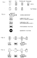
Die Symbole für die einzelnen Ladezustände der Energieträger (Akkus oder Batterien) sind in Fig. 1 dargestellt. Die vorhandene bzw. teilweise bzw. fehlende Schraffur zeigt in Verbindung mit dem Pfeil die Ladung und die Richtung des Stromflusses, d.h. ob entladen oder geladen, an.The symbols for the individual charge states of the energy sources (accumulators or batteries) are shown in FIG. 1. The existing or partial or missing hatching in connection with the arrow shows the charge and the direction of the current flow, i.e. whether unloaded or loaded, on.
In Fig. 2 sind die weiteren verwendeten Symbole aufgezeigt. Das Verbrauchergerät (VG) ist schematisch als Kamera dargestellt. Beim Ladegerät(LG)-Symbol ist zu unterscheiden zwischen Nur-Ladegerät (ohne Pfeil) und Ladegerät mit vorheriger bedarfsweiser Entladung (mit Pfeil) des Akkus. Die freigegebene und die gesperrte Richtung stellen die beiden letzten Symbole dar.2 shows the other symbols used. The consumer device (VG) is shown schematically as a camera. For the charger (LG) symbol, a distinction must be made between charger-only (without arrow) and charger with previous necessary discharge (with arrow) of the battery. The released and the locked direction represent the last two symbols.
Die Fig. 3 zeigt auf, daß ein voller Akku nur in ein VG eingelegt werden kann. Dasselbe gilt auch für eine volle Batterie bzw. einen Batterie-Pack. Die erlaubte Richtung für den Akku geht nur vom LG zum VG. Einsetzen und entnehmen des Akkus bzw. der Batterie in das und aus dem VG ist erlaubt.Fig. 3 shows that a full battery can only be inserted in a VG. The same applies to a full battery or a battery pack. The permitted direction for the battery only goes from the LG to the VG. Inserting and removing the rechargeable battery or the battery in and out of the VG is permitted.
Analog dazu zeigt die Fig. 4 den erlaubten Weg von leeren Energieträgern. Eine leere Batterie kann nur aus dem VG entnommen werden. Wird sie trotzdem wieder eingesetzt, muß die Warnung vom VG her aktiv werden, entweder akustisch oder optisch. Denkbar ist auch eine mechanische Sperre, die den Einsatz der Batterie unmöglich macht, wenn die Mindestkapazität der Batterie unterschritten ist. Die Messung der Mindestkapazität könnte während des versuchten Einlegens der Batterie in das VG erfolgen. Es könnte eine Sperre sein, die nur beim Vorhandensein einer zum Betrieb des VG ausreichenden Mindestkapazität mittels eines Elektromagneten zur Freigabe weggeschwenkt wird. Außer der mechanischen Sperre kann selbstverständlich auch eine elektronische Sperre oder elektronische Sperrung eingesetzt werden. Dieselbe Sperre verhindert auch den Einsatz eines leeren Akkus in das VG. Eine analoge Sperre, die verhindert, daß ein voller Akku in das LG eingesetzt wird, könnte Bestandteil des LG sein. Ein leerer Akku kann nur in das LG eingesetzt werden. Die Ladezustandsanzeige ist zweckmäßigerweise am Akku selbst angebracht.4 shows the permitted path of empty energy sources. An empty battery can only be removed from the VG. If it is used again, the warning must be activated from the VG either acoustically or optically. A mechanical lock is also conceivable, which makes the use of the battery impossible if the minimum capacity of the battery is undershot. The minimum capacity could be measured while trying to insert the battery into the VG. It could be a lock that is only pivoted away for release by means of an electromagnet if there is a minimum capacity sufficient to operate the gearbox. In addition to the mechanical lock, an electronic lock or electronic lock can of course also be used. The same lock also prevents the use of an empty battery in the VG. An analog lock that prevents a full battery from being inserted into the LG could be part of the LG. An empty battery can only be used in the LG. The charge status indicator is conveniently attached to the battery itself.
In Fig. 5 sind die erlaubten Einsätze von teilgeladenen bzw. teilentladenen Akkus dargestellt. Der Austausch von Energieträgern zwischen LG und VG ist nicht erlaubt, wie das Sperrzeichen verdeutlicht. Ein teilweise geladener Akku kann nur wieder in das LG eingelegt werden. Ebenso kann ein teilweise entladener Akku nur wieder in das VG eingesetzt werden.5 shows the permitted use of partially charged or partially discharged batteries. The exchange of energy sources between LG and VG is not allowed, as the lock symbol shows. A partially charged battery can only be reinserted into the LG. Similarly, a partially discharged battery can only be reinserted into the VG.
Anders sieht es nach den in Fig. 6 gezeigten Einsatzmöglichkeiten aus. Hier wird ebenfalls der erlaubte und unerlaubte Einsatz von teilgeladenen bzw. teilentladenen Akkus dargestellt. Unterschiedlich zu Fig. 5 ist nur, daß ein LG eingesetzt wird, das vor der Ladung des Akkus erst die noch vorhandene Ladungsmenge mißt und den Akku bedarfsweise entlädt. Erst nach der Entladung beginnt der Ladevorgang.The situation is different according to the possible uses shown in FIG. 6. The permitted and unauthorized use of partially charged or partially discharged batteries is also shown here. The only difference to Fig. 5 is that a LG is used, which before Charging the battery only measures the amount of charge still present and discharges the battery if necessary. The charging process only begins after the discharge.
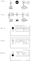
In den Fig. 7a bis 7c ist ein Ausführungsbeispiel einer Display-Anzeige, kombiniert mit LED-Anzeigen in einem Akku aufgezeigt.7a to 7c show an exemplary embodiment of a display, combined with LED displays in a battery.
Die Fig. 7a zeigt die Einsatzfähigkeit eines Akkus in ein VG. Die Zeitangabe gibt die Betriebsrestzeit wieder, die obere LED leuchtet. Der Zähler arbeitet subtrahierend.7a shows the usability of a battery in a VG. The time specification shows the remaining operating time, the upper LED lights up. The counter works subtracting.
In Fig. 7b ist der Leerzustand des Akkus erreicht. Das Display zeigt eine Betriebs-Restzeit von 0 h 00 min an, die obere LED blinkt. Der Akku darf nicht wieder in das VG eingesetzt werden.7b the battery is empty. The display shows an operating time of 0
Schließlich veranschaulicht Fig. 7c den Anzeigezustand des Displays, wenn ein leerer Akku in ein LG eingelegt ist und geladen wird. Die Anzeige gibt die Lade-Restzeit wieder. Die untere LED leuchtet. Der Zähler arbeitet subtrahierend. Die Lade-Restzeit bewegt sich auf Null zu. Die Anzeige bleibt auch erhalten, wenn während des Ladevorgangs der Akku aus dem LG entnommen wird. Er kann dann aber jederzeit wieder in das LG eingesetzt werden. Erst wenn der Akku voll geladen ist, geht er wieder in einen Anzeigezustand analog Fig. 7a.Finally, FIG. 7c illustrates the display state of the display when an empty battery is inserted in an LG and is being charged. The display shows the remaining charging time. The lower LED lights up. The counter works subtracting. The remaining charge time moves to zero. The display is retained even if the battery is removed from the LG during the charging process. However, it can then be reinstalled in the LG at any time. Only when the battery is fully charged does it return to a display state analogous to FIG. 7a.
Die Figuren 3 bis 6 sollen nur veranschaulichen, welche Einsätze der Energieträger in Abhängigkeit ihrer Ladung erlaubt und nicht erlaubt sind. Die Realisierungsmöglichkeiten sind vielfältig und unterliegen mehreren Einflüssen, wie Platzbedarf und Kosten und sind deshalb nach Entscheidung des Konstrukteurs auszuwählen.Figures 3 to 6 are only intended to illustrate which uses of the energy carriers are permitted and not permitted depending on their charge. The Realization options are diverse and are subject to several influences, such as space requirements and costs, and are therefore to be selected after the designer's decision.
Claims (11)
gekennzeichnet durch folgende Merkmale:
Die Steuereinrichtung ist derart ausgestaltet, daß
characterized by the following features:
The control device is designed such that
dadurch gekennzeichnet, daß die Steuereinrichtung derart ausgestaltet ist, daß
und/oder
verhindert wird.
characterized in that the control device is designed such that
and or
is prevented.
dadurch gekennzeichnet, daß der Akku eine Ladungsbestimmungs-Einrichtung beinhaltet, die bei Entnahme des Akkus aus dem Verbrauchergerät oder Ladegerät automatisch die Ladung mißt und automatisch oder durch eine Tastenbetätigung den Ladezustand anzeigt.Device according to claim 1 and 2,
characterized in that the battery includes a charge determination device which automatically measures the charge when the battery is removed from the consumer device or charger and indicates the charge status automatically or by pressing a button.
dadurch gekennzeichnet, daß die Ladungsanzeige über ein Display und/oder LED's erfolgt, wobei das Display in Abhängigkeit von der Stromflußrichtung die geladene Ladungsmenge oder die Restladung anzeigt.Device according to claim 3,
characterized in that the charge is indicated on a display and / or LEDs, the display showing the amount of charge or the remaining charge depending on the direction of current flow.
dadurch gekennzeichnet, daß beim Entnehmen des Akkus aus dem Verbrauchergerät die Restladung und beim Entnehmen aus dem Ladegerät die noch zu ladende bzw. schon geladene Lademenge angezeigt wird.Device according to claim 4,
characterized in that when the battery is removed from the consumer device, the remaining charge and when it is removed from the charger, the amount still to be charged or already charged is displayed.
dadurch gekennzeichnet, daß die Anzeige der Lademenge des Akkus bei Entnahme aus dem Ladegerät wahlweise als noch zu ladende oder als schon geladene Ladungsmenge erfolgt.Device according to claim 5,
characterized in that the amount of charge of the battery is displayed when removed from the charger either as a charge to be charged or as a charge already charged.
dadurch gekennzeichnet, daß die Anzeige als Zeitanzeige im Display erfolgt.Device according to claims 5 and 6,
characterized in that the display is made as a time display.
dadurch gekennzeichnet, daß der Akku eine elektromechanische Einrichtung mit mechanischen Sperren oder eine elektronische Sperre besitzt, welche, dem Ladezustand des Akkus entsprechend, den Einsatz des Akkus in das Verbrauchergerät oder in das Ladegerät sperren.Device according to one or more of claims 1 to 6,
characterized in that the battery has an electromechanical device with mechanical locks or an electronic lock which, according to the state of charge of the battery, block the use of the battery in the consumer device or in the charger.
dadurch gekennzeichnet, daß das Verbrauchergerät eine akustische oder optische Signaleinrichtung besitzt, die kurz vor dem Erreichen des entladenen Zustands des Akkus aktiv wird.Device according to claim 1 and 2,
characterized in that the consumer device has an acoustic or optical signal device which is active shortly before reaching the discharged state of the battery.
dadurch gekennzeichnet, daß das Verbrauchergerät eine Messeinrichtung zur Anzeige der Restkapazität des Akkus oder der Batterie besitzt.Device according to one or more of claims 1 to 9,
characterized in that the consumer device has a measuring device for displaying the remaining capacity of the battery or the battery.
dadurch gekennzeichnet, daß das Verbrauchergerät eine elektromechanische Sperre enthält, die aktiv wird, wenn ein leerer Akku oder eine leere Batterie eingesetzt werden soll.Device according to one or more of claims 1 to 10,
characterized in that the consumer device contains an electromechanical lock which becomes active when an empty battery or an empty battery is to be used.
Applications Claiming Priority (2)
| Application Number | Priority Date | Filing Date | Title |
|---|---|---|---|
| DE4142677A DE4142677C1 (en) | 1991-12-21 | 1991-12-21 | |
| DE4142677 | 1991-12-21 |
Publications (1)
| Publication Number | Publication Date |
|---|---|
| EP0549950A1 true EP0549950A1 (en) | 1993-07-07 |
Family
ID=6447952
Family Applications (1)
| Application Number | Title | Priority Date | Filing Date |
|---|---|---|---|
| EP92121354A Withdrawn EP0549950A1 (en) | 1991-12-21 | 1992-12-16 | Arrangement for locking against inserting of batteries which are not in regular states of charge into electric appliances and/or charges |
Country Status (2)
| Country | Link |
|---|---|
| EP (1) | EP0549950A1 (en) |
| DE (1) | DE4142677C1 (en) |
Cited By (11)
| Publication number | Priority date | Publication date | Assignee | Title |
|---|---|---|---|---|
| EP0588728A1 (en) * | 1992-09-18 | 1994-03-23 | Sony Corporation | Battery pack |
| US5399446A (en) * | 1992-06-30 | 1995-03-21 | Sony Corporation | Battery cartridge having a terminal for transferring information therefrom |
| US5415947A (en) * | 1992-05-29 | 1995-05-16 | Sony Corporation | Battery cartridge having a recess for detecting misuse and/or recessed terminals |
| US5437938A (en) * | 1992-03-06 | 1995-08-01 | Sony Corporation | Battery pack |
| US5465117A (en) * | 1992-09-02 | 1995-11-07 | Sony Corporation | Connecting apparatus for a video tape recorder having a built-in camera |
| US6075341A (en) * | 1999-02-17 | 2000-06-13 | Black & Decker Inc. | Power pack charging system for a power tool |
| JP2002320341A (en) * | 2001-02-14 | 2002-10-31 | Sony Corp | Charge/discharge device and method therefor, power supply device and method therefor, power supply system and method therefor, program storage medium, and program thereof |
| JP2007325498A (en) * | 2001-02-14 | 2007-12-13 | Sony Corp | Charger/discharger and charging/discharging method, power supply device and method, power supply system and method, program storage medium, and program |
| JP2007325499A (en) * | 2001-02-14 | 2007-12-13 | Sony Corp | Charger/discharger and charging/discharging method, power supply device and method, power supply system and method, program storage medium, and program |
| JP2007325500A (en) * | 2001-02-14 | 2007-12-13 | Sony Corp | Charger/discharger and charging/discharging method, power supply device and method, power supply system and method, program storage medium, and program |
| EP2919315A4 (en) * | 2012-11-09 | 2016-07-20 | Pérez Enrique Micó | Device for locking batteries and method for using same |
Citations (3)
| Publication number | Priority date | Publication date | Assignee | Title |
|---|---|---|---|---|
| DD251440A1 (en) * | 1986-07-23 | 1987-11-11 | Koepenick Funkwerk Veb | ENERGY SUPPLY SYSTEM FOR BATTERY-OPERATED DEVICES |
| DE3637669A1 (en) * | 1986-11-05 | 1988-05-19 | Bosch Gmbh Robert | Device for automatically detecting the electrical characteristic values of an accumulator (rechargeable battery) |
| US5057383A (en) * | 1990-03-30 | 1991-10-15 | Anton/Bauer, Inc | Battery system |
Family Cites Families (1)
| Publication number | Priority date | Publication date | Assignee | Title |
|---|---|---|---|---|
| DE9013562U1 (en) * | 1989-09-28 | 1990-11-29 | Landwehr Electronic Gmbh, 2000 Norderstedt, De |
-
1991
- 1991-12-21 DE DE4142677A patent/DE4142677C1/de not_active Expired - Fee Related
-
1992
- 1992-12-16 EP EP92121354A patent/EP0549950A1/en not_active Withdrawn
Patent Citations (3)
| Publication number | Priority date | Publication date | Assignee | Title |
|---|---|---|---|---|
| DD251440A1 (en) * | 1986-07-23 | 1987-11-11 | Koepenick Funkwerk Veb | ENERGY SUPPLY SYSTEM FOR BATTERY-OPERATED DEVICES |
| DE3637669A1 (en) * | 1986-11-05 | 1988-05-19 | Bosch Gmbh Robert | Device for automatically detecting the electrical characteristic values of an accumulator (rechargeable battery) |
| US5057383A (en) * | 1990-03-30 | 1991-10-15 | Anton/Bauer, Inc | Battery system |
Cited By (19)
| Publication number | Priority date | Publication date | Assignee | Title |
|---|---|---|---|---|
| US5437938A (en) * | 1992-03-06 | 1995-08-01 | Sony Corporation | Battery pack |
| US5415947A (en) * | 1992-05-29 | 1995-05-16 | Sony Corporation | Battery cartridge having a recess for detecting misuse and/or recessed terminals |
| US5399446A (en) * | 1992-06-30 | 1995-03-21 | Sony Corporation | Battery cartridge having a terminal for transferring information therefrom |
| US5465117A (en) * | 1992-09-02 | 1995-11-07 | Sony Corporation | Connecting apparatus for a video tape recorder having a built-in camera |
| US5568198A (en) * | 1992-09-02 | 1996-10-22 | Sony Corporation | Power supplying apparatus for a connecting apparatus and a video tape recorder having a built-in camera |
| US5602454A (en) * | 1992-09-18 | 1997-02-11 | Sony Corporation | Battery pack having identification recesses and terminals |
| EP0588728A1 (en) * | 1992-09-18 | 1994-03-23 | Sony Corporation | Battery pack |
| JP2012135210A (en) * | 1999-02-17 | 2012-07-12 | Black & Decker Inc | Power pack charging system and power tool charging system |
| US6075341A (en) * | 1999-02-17 | 2000-06-13 | Black & Decker Inc. | Power pack charging system for a power tool |
| JP2002320341A (en) * | 2001-02-14 | 2002-10-31 | Sony Corp | Charge/discharge device and method therefor, power supply device and method therefor, power supply system and method therefor, program storage medium, and program thereof |
| EP1300921A4 (en) * | 2001-02-14 | 2005-04-13 | Sony Corp | Charging/discharging device and method, power supplying device and method, power supplying system and method, progrom storing medium, and program |
| JP2007325498A (en) * | 2001-02-14 | 2007-12-13 | Sony Corp | Charger/discharger and charging/discharging method, power supply device and method, power supply system and method, program storage medium, and program |
| JP2007325499A (en) * | 2001-02-14 | 2007-12-13 | Sony Corp | Charger/discharger and charging/discharging method, power supply device and method, power supply system and method, program storage medium, and program |
| JP2007325500A (en) * | 2001-02-14 | 2007-12-13 | Sony Corp | Charger/discharger and charging/discharging method, power supply device and method, power supply system and method, program storage medium, and program |
| US7411373B2 (en) | 2001-02-14 | 2008-08-12 | Sony Corporation | Charging/discharging apparatus and method, power supplying apparatus and method, power supplying system and method, program storing medium, and program |
| US7525288B2 (en) | 2001-02-14 | 2009-04-28 | Sony Corporation | Charging/discharging apparatus and method, power supplying apparatus and method, power supplying system and method, program storing medium, and program |
| US7615963B2 (en) | 2001-02-14 | 2009-11-10 | Sony Corporation | Charging/discharging apparatus and method, power supplying device and method, power supplying systems and method, program storing medium, and program |
| EP1300921A1 (en) * | 2001-02-14 | 2003-04-09 | Sony Corporation | Charging/discharging device and method, power supplying device and method, power supplying system and method, progrom storing medium, and program |
| EP2919315A4 (en) * | 2012-11-09 | 2016-07-20 | Pérez Enrique Micó | Device for locking batteries and method for using same |
Also Published As
| Publication number | Publication date |
|---|---|
| DE4142677C1 (en) | 1993-07-08 |
Similar Documents
| Publication | Publication Date | Title |
|---|---|---|
| DE69924860T2 (en) | BATTERY WITH CHARGE INDICATOR | |
| DE4225088C2 (en) | Battery discharge device | |
| DE3736481C2 (en) | Method and device for determining the energy content of electrochemical energy stores | |
| DE4142677C1 (en) | ||
| DE102007031568A1 (en) | Device, in particular charger device, for charging a rechargeable battery | |
| AT506665A1 (en) | POWER SUPPLY FOR AN ELECTRONIC DEVICE PROVIDED WITH A THEFT METER | |
| WO1994014079A1 (en) | Charge-status indicator | |
| DE4106725A1 (en) | BATTERY CHARGE LEVEL INDICATOR | |
| EP0280916A1 (en) | Process and appliance for monitoring the working condition of a battery-driven vehicle | |
| DE102007062648A1 (en) | Apparatus for generating electrical energy in firearms | |
| DE202015106271U1 (en) | Battery pack with switchable total capacity | |
| WO2003033057A1 (en) | Injection device comprising an energy accumulator | |
| DE4025703C2 (en) | ||
| WO1998001917A2 (en) | Accumulator and charging set for an accumulator | |
| DE102008008594A1 (en) | Portable electronic device, charging station, arrangement with a portable electronic device and a charging station and method for charging two batteries | |
| EP0523526A2 (en) | Monitoring device for accumulators | |
| DE102013100471B4 (en) | Method for determining a state of charge of an energy store with at least one energy cell | |
| EP0505622A2 (en) | Circuit for measuring and displaying the remaining capacity of an accumulator | |
| DE202014106185U1 (en) | Device for charging, in particular for sequential charging, of rechargeable batteries | |
| DE4420087C2 (en) | Device for identifying a predetermined state of charge of primary or secondary elements | |
| EP0458232A2 (en) | Control- and measurement device for mobile battery powered equipment | |
| WO2015067560A1 (en) | Apparatus with a battery module and circuit arrangement for detecting cell exchange by unauthorized persons | |
| DE4424337C2 (en) | Method for setting the hands of an electric clock and corresponding clock | |
| DE3910373A1 (en) | ELECTRIC SHAVER | |
| EP3035488B1 (en) | Method and device for charging, in particular for sequential charging of rechargeable batteries and emergency charging of severely drained batteries |
Legal Events
| Date | Code | Title | Description |
|---|---|---|---|
| PUAI | Public reference made under article 153(3) epc to a published international application that has entered the european phase |
Free format text: ORIGINAL CODE: 0009012 |
|
| AK | Designated contracting states |
Kind code of ref document: A1 Designated state(s): DE FR GB IT |
|
| 17P | Request for examination filed |
Effective date: 19930603 |
|
| 17Q | First examination report despatched |
Effective date: 19940617 |
|
| STAA | Information on the status of an ep patent application or granted ep patent |
Free format text: STATUS: THE APPLICATION HAS BEEN WITHDRAWN |
|
| 18W | Application withdrawn |
Withdrawal date: 19941010 |