EP0556748A2 - Method and apparatus for particle manipulation, and measuring apparatus utilizing the same - Google Patents
Method and apparatus for particle manipulation, and measuring apparatus utilizing the same Download PDFInfo
- Publication number
- EP0556748A2 EP0556748A2 EP93102257A EP93102257A EP0556748A2 EP 0556748 A2 EP0556748 A2 EP 0556748A2 EP 93102257 A EP93102257 A EP 93102257A EP 93102257 A EP93102257 A EP 93102257A EP 0556748 A2 EP0556748 A2 EP 0556748A2
- Authority
- EP
- European Patent Office
- Prior art keywords
- particles
- particle
- light
- laser
- flow
- Prior art date
- Legal status (The legal status is an assumption and is not a legal conclusion. Google has not performed a legal analysis and makes no representation as to the accuracy of the status listed.)
- Granted
Links
- 239000002245 particle Substances 0.000 title claims abstract description 105
- 238000000034 method Methods 0.000 title claims description 22
- 230000001678 irradiating effect Effects 0.000 claims abstract description 13
- 230000003287 optical effect Effects 0.000 claims description 45
- 230000005855 radiation Effects 0.000 claims description 9
- 239000010419 fine particle Substances 0.000 abstract description 74
- 239000007788 liquid Substances 0.000 abstract description 20
- 210000004027 cell Anatomy 0.000 description 19
- 239000002612 dispersion medium Substances 0.000 description 19
- 239000002609 medium Substances 0.000 description 8
- 239000006185 dispersion Substances 0.000 description 7
- 238000000651 laser trapping Methods 0.000 description 5
- 230000000694 effects Effects 0.000 description 4
- 244000005700 microbiome Species 0.000 description 4
- 238000000926 separation method Methods 0.000 description 4
- VYPSYNLAJGMNEJ-UHFFFAOYSA-N Silicium dioxide Chemical compound O=[Si]=O VYPSYNLAJGMNEJ-UHFFFAOYSA-N 0.000 description 3
- 241000700605 Viruses Species 0.000 description 3
- 238000004458 analytical method Methods 0.000 description 3
- 238000005516 engineering process Methods 0.000 description 3
- 230000005484 gravity Effects 0.000 description 3
- ORQBXQOJMQIAOY-UHFFFAOYSA-N nobelium Chemical compound [No] ORQBXQOJMQIAOY-UHFFFAOYSA-N 0.000 description 3
- 230000010287 polarization Effects 0.000 description 3
- XLYOFNOQVPJJNP-UHFFFAOYSA-N water Substances O XLYOFNOQVPJJNP-UHFFFAOYSA-N 0.000 description 3
- 210000000601 blood cell Anatomy 0.000 description 2
- 230000008859 change Effects 0.000 description 2
- 238000006243 chemical reaction Methods 0.000 description 2
- 230000008602 contraction Effects 0.000 description 2
- 239000004816 latex Substances 0.000 description 2
- 229920000126 latex Polymers 0.000 description 2
- 230000007246 mechanism Effects 0.000 description 2
- 238000012544 monitoring process Methods 0.000 description 2
- 229920001296 polysiloxane Polymers 0.000 description 2
- 230000001105 regulatory effect Effects 0.000 description 2
- 238000002835 absorbance Methods 0.000 description 1
- 238000010521 absorption reaction Methods 0.000 description 1
- 230000009471 action Effects 0.000 description 1
- 230000004913 activation Effects 0.000 description 1
- 238000013459 approach Methods 0.000 description 1
- 238000005452 bending Methods 0.000 description 1
- 230000015572 biosynthetic process Effects 0.000 description 1
- 238000004364 calculation method Methods 0.000 description 1
- 239000000919 ceramic Substances 0.000 description 1
- 230000005494 condensation Effects 0.000 description 1
- 238000009833 condensation Methods 0.000 description 1
- 230000001276 controlling effect Effects 0.000 description 1
- 238000001816 cooling Methods 0.000 description 1
- 238000007599 discharging Methods 0.000 description 1
- 238000010291 electrical method Methods 0.000 description 1
- 238000000684 flow cytometry Methods 0.000 description 1
- 238000002309 gasification Methods 0.000 description 1
- 239000000499 gel Substances 0.000 description 1
- 239000011521 glass Substances 0.000 description 1
- 229910052736 halogen Inorganic materials 0.000 description 1
- 150000002367 halogens Chemical class 0.000 description 1
- 239000004973 liquid crystal related substance Substances 0.000 description 1
- 238000005259 measurement Methods 0.000 description 1
- 230000004048 modification Effects 0.000 description 1
- 238000012986 modification Methods 0.000 description 1
- 239000004033 plastic Substances 0.000 description 1
- 238000012545 processing Methods 0.000 description 1
- 239000004065 semiconductor Substances 0.000 description 1
- 238000007873 sieving Methods 0.000 description 1
- 238000002834 transmittance Methods 0.000 description 1
- 239000012780 transparent material Substances 0.000 description 1
- 229910052724 xenon Inorganic materials 0.000 description 1
- FHNFHKCVQCLJFQ-UHFFFAOYSA-N xenon atom Chemical compound [Xe] FHNFHKCVQCLJFQ-UHFFFAOYSA-N 0.000 description 1
Images


Classifications
-
- H—ELECTRICITY
- H05—ELECTRIC TECHNIQUES NOT OTHERWISE PROVIDED FOR
- H05H—PLASMA TECHNIQUE; PRODUCTION OF ACCELERATED ELECTRICALLY-CHARGED PARTICLES OR OF NEUTRONS; PRODUCTION OR ACCELERATION OF NEUTRAL MOLECULAR OR ATOMIC BEAMS
- H05H3/00—Production or acceleration of neutral particle beams, e.g. molecular or atomic beams
- H05H3/04—Acceleration by electromagnetic wave pressure
-
- G—PHYSICS
- G01—MEASURING; TESTING
- G01N—INVESTIGATING OR ANALYSING MATERIALS BY DETERMINING THEIR CHEMICAL OR PHYSICAL PROPERTIES
- G01N15/00—Investigating characteristics of particles; Investigating permeability, pore-volume, or surface-area of porous materials
- G01N15/10—Investigating individual particles
- G01N15/14—Electro-optical investigation, e.g. flow cytometers
-
- G—PHYSICS
- G01—MEASURING; TESTING
- G01N—INVESTIGATING OR ANALYSING MATERIALS BY DETERMINING THEIR CHEMICAL OR PHYSICAL PROPERTIES
- G01N30/00—Investigating or analysing materials by separation into components using adsorption, absorption or similar phenomena or using ion-exchange, e.g. chromatography or field flow fractionation
-
- G01N15/149—
-
- G—PHYSICS
- G01—MEASURING; TESTING
- G01N—INVESTIGATING OR ANALYSING MATERIALS BY DETERMINING THEIR CHEMICAL OR PHYSICAL PROPERTIES
- G01N30/00—Investigating or analysing materials by separation into components using adsorption, absorption or similar phenomena or using ion-exchange, e.g. chromatography or field flow fractionation
- G01N30/02—Column chromatography
Definitions
- the present invention relates to a technology for manipulating movement of particles in a medium.
- Sheath flow method is already well known for transporting fine particles dispersed in a medium such as liquid, in linear array one by one.
- a medium such as liquid
- sheath flow method is applied to so-called flow cytometry which is used for counting the number of such fine particles by optical or electrical method or for identifying the sort or property of such particles by statistical processing of a number of thus obtained data.
- the present invention is to provide a novel method for manipulating particles in a medium.
- a more specific object of the present invention is to provide novel method and apparatus for continuously transporting particles in an array with a desired interval.
- Another more specific object of the present invention is to provide novel method and apparatus for separating particles different in size or in refractive index.
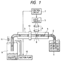
- Fig. 1 is a view showing the configuration of an apparatus constituting a first embodiment of the present invention, wherein a supply container 1 contains therein dispersion of fine particles, consisting of a plurality of fine particles (for example, blood cells, viruses, microorganisms, bioparticles such as DNA or RNA, carrier particles or industrial particles) and dispersion medium.
- the fine particles and the dispersion medium have comparable specific gravities.
- the fine particles are latex particles of a given size while the dispersion medium is water.
- the supply container 1 is connected to a flow path 2, which is provided with a flow cell 3 of quartz glass in the middle and connected to a discharge container 9.
- a vacuum pump 10 and a valve 11 are connected to the discharge container 9.
- the vaccum pump 10 is constantly operated to generate a low pressure in the discharge container 9, thereby creating a flow of particle dispersion of a constant velocity in the flow path 2.
- the fine particles 4 in the dispersion medium move together with the flow.
- the internal diameter of the flow path 2 has to be larger than the diameter of the largest particle, but preferably does not exceed twice of the diameter of the largest particle, since an excessively large internal diameter increases the possibility of simultaneous flowing of plural particles.
- a light source 5, positioned above the flow cell 3, generates a light beam of a predetermined intensity gradient for optical trapping, and is so selected that the wavelength thereof is in a low optical absorption band of the particles.
- a TEM00 mode of YAG laser to generate a Gaussian beam
- various lasers such as solid-state laser, gas laser or semiconductor laser, or light sources not limited to laser, capable of generating light having intensity gradient.
- the light beam emitted by the light source 5 is focused by a lens system 6 to a position 8 in the flow path in the flow cell 3.
- a control means 7 controls the light source 5 itself or light control means (such as a shutter or a light modulating element) separate from the light source 5, thereby effecting on-off control or intensity modulation of the light irradiation on the irradiation position 8.
- the control means 7 also sends instruction to the vacuum pump 10.
- particle measuring means 13 utilizing, for example, optical, electrical, magnetic or acoustooptical method.
- the fine particle When the fine particle passes the irradiation position 8 while the light beam is focused thereon, the fine particle is subjected to two forces, namely, an axial force toward the irradiating direction of the light beam, and a radial force to confine the particle in the optical axis.
- Each of the forces depends on the intensity of the laser beam and the intensity distribution along the optical axis, namely, degree of condensation by the lens and the intensity distribution in a direction perpendicular to the optical axis. They also depend on the refractive index and absorbance (reflectance) of the particle, and on the particle size.
- the radial force the fine particle may be stopped by trapping at the irradiation position 8, or the moving velocity of the particle may be temporarily reduced close to zero.
- the fine particle is not subjected to such forces when the light irradiation is not conducted, and moves together with the flow of the dispersion medium. Consequently, the irradiation of the light beam is repeated by turning on and off at a constant interval under the control of the control means (for example, the light beam on for 1 second and off for 0.1 seconds), whereby gate function with constant period can be applied to the moving fine particles.
- the fine particles can be moved with a desired constant spacing in the flow path behind the irradiating position 8.
- the fine particles move in succession from the supply container 1 to the irradiating position 8 as shown in Fig. 1.
- the period of off-irradiation in which the particle can pass
- the period of on-irradiation is made shorter than the period of on-irradiation (trapping period), so that plural particles do not pass through the irradiating position at a time.
- the spacing of the fine particles in movement may be arbitrarily varied by a variation in the cycle time of the light irradiation.
- the irradiating light intensity need not necessarily be brought to zero, but may be reduced to a level not causing the particle trapping.
- the trapping may be conducted by methods explained in eighth and subsequent embodiments.
- Fig. 2 illustrates the configuration of a part of the apparatus of a second embodiment of the present invention, which is a partial modification of the embodiment shown in Fig. 1 and in which non-illustrated components are the same as those in Fig. 1.
- the flow path 2 in a flow cell 12 is bent in key-shape, and the light for optically trapping is irradiated on the flow path in front of the bent portion, in a direction along the flow path.
- the present embodiment effects the light irradiation in a direction opposite to the flow of the fine particles, thereby trapping the particle by both the axial and radial forces.
- the trapping may be achieved by methods explained in eighth and subsequent embodiments.
- FIG. 3 shows the configuration of an apparatus constituting a third embodiment of the present invention.
- a supply container 20 contains particle dispersion in which a number of fine particles float in a dispersion medium.
- a supply container 20 contains particle dispersion in which a number of fine particles float in a dispersion medium.
- the flow cell 22 is in turn connected to a silicone tube 23, of which the other end is connected to a nozzle 24 equipped with a micropump 25, to be explained below.
- a pump which can be exemplified by a vacuum pump for sucking the dispersion medium from the side of the discharge container, a pressure pump for pressurizing the dispersion medium from the side of the supply container, or a feed pump having a liquid feeding mechanism.
- the vacuum pump is employed in the first embodiment, the present embodiment employs a micropump constituting a feed pump. More specifically, the micropump includes a heat-generating element provided. When a pulse voltage is given to the heat-generating element, the liquid heated by the generated heat is gasified instantaneously to generate a bubble, and liquid drops are discharged from the nozzle 24 by a pressure generated by the impact due to expansion or contraction of the bubble.
- the particle dispersion is sucked in toward the nozzle, corresponding to the amount of such discharge.
- a feeding action on the particle dispersion is obtained by effecting the discharge in consecutive manner with a high frequency to form a flow in the flow cell 22.
- the fine particles move together with the flow.
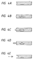
- Figs. 4A to 4E illustrate the mode of liquid droplet discharged by bubble generation.
- the heat-generating element is heated instantaneously by a pulse voltage in an initial state shown in Fig. 4A
- the liquid in the vicinity of the element is gasified to generate a bubble as shown in Fig. 4B.
- the liquid in the vicinity of the nozzle aperture is pushed out from the aperture as shown in Fig. 4C.
- the bubble originally expanding starts to contract by cooling as shown in Fig. 4D, and the liquid pushed out from the aperture forms a liquid droplet and flies in the air as shown in Fig. 4E, because of the volume contraction.
- the liquid is replenished by capillary phenomena, corresponding to the discharged volume, whereby the initial state shown in Fig. 4A is restored.
- the basic principle of the liquid droplet discharging by bubble formation is detailedly described, for example, in U.S. Patent Nos. 4,732,129 and 4,740,796.
- micropump it is also possible to replace the heat-generating element with a piezoelectric element and to apply an electric pulse thereto, thereby emitting a liquid droplet by a pressure generated by the impact due to volume change of the piezoelectric element.
- a cylindrical piezoelement which is so provided as to surround the flow path.
- the liquid feeding ability of the micropump can be selected by the voltage and frequency of the electric pulse given to the heat-generating element or the piezoelectric element.
- the voltage and frequency supplied to the micropump 25 are so selected as to obtain a flow of the velocity in the order of 200 ⁇ m/sec. in the flow path of the flow cell 22.
- a light source 26 is composed of a YAG laser (1064 nm) for providing the fine particle with axial and radial forces, and the light for trapping the particle is condensed by a lens system 27 onto the flow path in the flow cell 22.
- Another light source 28 is composed of an Ar+ laser (488 nm) for measuring the optical characteristics of the fine particle, and the light for particle measurement is focused by a lens system 29 onto the flow path in the flow cell 22.
- the light emitted from the fine particle irradiated by the lens system 29 is collected by a lens system 30 and received by a photodetector 31 (photomultiplier or photodiode).
- a control means 32 effects the control of the light sources 26, 28, the analysis of the particle by the output from the photodetector 31, and the driving of the micropump 25.
- the fine particles moving in the flow path can be trapped against the flow.
- the trapping is released and the fine particle moves again together with the flow. It is therefore possible, as in the foregoing embodiments, to control the spacing of the fine particles separately flowing one by one in the flow path, by turning on and off the irradiation of the light source 26 with a suitable interval corresponding to the flow velocity and the concentration of the fine particles, under the control of the control means 32.
- the fine particles flowing in such array pass the irradiation position of the light source 28 in succession, and the light emitted from each particle (scattered, transmitted or fluorescent light) upon such passing is detected by the photodetector 31.
- the detected data are fetched by the control means 32, which effects the analysis such as the identification of sort and property of the particles, based on the data obtained from a plurality of particles.
- the trapping may be made by methods of eighth and subsequent embodiments to be explained later.
- Fig. 5 illustrates the configuration of an apparatus constituting a fourth embodiment of the present invention, in which the particle movement is achieved by the radiation pressure instead of the pump.
- a first resorvoir 41 and a second reservoir 42 which are mutually connected by paths 43, 44.
- Each of the paths 43, 44 has a square cross section, of which size is selected larger than the maximum diameter of a plurality of particles, but smaller than twice of the maximum diameter.
- first and second laser beams are provided respectively, corresponding to the laser light sources.
- Laser beams emitted from the laser light sources 45, 47 are converted, respectively by the lens systems 46, 48, into parallel light beams (called first and second laser beams).
- An axial force is applied by the laser beams on the fine particles present in the light beams, in the directions of incidence of the laser beams, thereby moving the fine particles along the optical axes. Since the first and second laser beams have Gaussian intensity distribution, there can be obtained an effect that the fine particle once caught in the light beam is attracted to the optical axis by the radial force and is not released from the light beam.
- the first laser beam irradiating the path 43 crosses the second laser beam irradiating the path 44, and, at the crossing point, the radiation pressure of the second light beam is set larger than that of the first laser beam, so that the fine particles moved by the radiation pressure are smoothly moved from the path 43 to the path 44.
- the laser beam emitted from the laser light source 49 is converted, by the lens system 50, into a converging light beam (called third laser beam) condensed on the path 43, thereby providing the fine particle with a radial force for particle trapping, against the axial force of the first laser beam from the laser light source 45.
- the third laser beam is irradiated on a position in front of the crossing point of the first and second light beams, but the third light beam may also be irradiated on the crossing point of the first and second light beams.
- the measured system includes, for effecting measuring light irradiation on the individually moving fine particles, a light source 52 (such as laser light source, halogen light source or xenon light source) and a lens system 53.
- a light source 52 such as laser light source, halogen light source or xenon light source
- a lens system 53 Among the lights emitted from the irradiated fine particle, the scattered light is detected by a lens 54 and a photodetector 5 while the fluorescent light is detected by a lens 56 and a photodetector 57.
- the outputs from the photodetectors 55, 57 are fetched by the control means 51 for the calculation for particle analysis.
- a control means 51 suitably selects the on-off interval of the third laser, whereby the particles move in array with a predetermined spacing in the path 44 without mutual adhesion or overlapping of the particles.
- Fig. 7 shows the configuration of an apparatus constituting a fifth embodiment, which is simplified from the configuration of the foregoing fourth embodiment.
- the light from a laser light source is split by a beam splitter into three laser beams. Also, no path is provided for guiding the moving particles.
- a light source 61 is composed of a YAG laser.
- a beam transmitted by a beam splitter 62 and a lens 67 and split by a beam splitter 63 is further reflected by mirrors 65, 66 and introduced as the first laser beam into the container 60 (direction A).
- a laser beam transmitted by the beam splitter 62, lens 67 and beam splitter 63 is introduced into the container 60 as the second laser beam (direction B).
- a laser beam emitted from the light source 61 and split by the beam splitter 62 is reflected by a mirror 64, then transmitted by a shutter 68 and focused by a lens 69 as the third laser beam onto the optical axis of the first laser beam.
- the positional relationship of the first, second and third laser beams is similar to that in the foregoing fourth embodiment.
- a measuring system similar to that shown in Fig. 6 in order to optically measure the fine particles moved in array in the direction B.
- the spacing in transportation of the particles is determined by on-off control of the irradiation of the third laser beam for optical trapping, through switching of the shutter 68 (liquid crystal shutter or mechanical shutter) under the control of a control means 70.
- the shutter may also be replaced by an optical modulation element, such as an acoustooptical element.
- the trapping force acting on the particle becomes larger, as the particle size increases or as the difference in refractive index between the particle and the dispersion medium becomes larger (in the case the refractive index of the particle is larger than that of the dispersion medium).
- the trapping force acting thereon becomes larger, as the light intensity for optical trapping becomes stronger, or as the focused spot size of the light becomes smaller, or as the wavelength of the light becomes shorter. Consequently, the particles may be trapped or not depending on the size or the refractive index thereof.
- Fig. 8 illustrates the configuration of an apparatus constituting a sixth embodiment, wherein a specimen container 85 contains liquid consisting of at least two different particles and a dispersion medium (for example, water).
- the fine particles and dispersion medium have comparable specific gravities.
- the different particles are defined to be different in (1) size, (2) refractive index, or (3) size and refractive index.
- the fine particles include cells, viruses, microorganisms, bioparticles such as DNA or RNA, carrier particles and industrial particles.
- a container 80 contains the dispersion medium (for example, water).
- the flow path 2 includes a flow cell 3 of quartz glass in the middle, and is connected to a discharge chamber 81.
- the chamber 81 can be maintained in a hermetically sealed condition by closing a valve 11.
- a fraction container 88 into which the liquid having passed the flow path 2 is charged.
- the interior of the discharge chamber 81 is maintained at a low pressure by the activation of a vacuum pump 10, thereby forming a flow of the dispersion medium including the fine particles, in the flow path 2.
- particle measuring means 13 utilizing, for example, an optical, electrical, magnetic or acoustooptical method.
- the intensity of the trapping light beam emitting from a light source 5 and irradiated on the position 8 is rendered adjustable. This adjustment can be achieved, for example, by (1) controlling the emission intensity of the light source 5, (2) regulating the irradiating light amount by placing a modulation element or a filter in the optical path, or (3) regulating the practical light amount by varying the focused spot size at the irradiation position through adjustment of a lens 6.
- the joint valve 82 is connected to the tube 86 to introduce a small amount of the particle dispersion from the specimen container 85 into the flow path 2. Then, the joint valve 82 is switched to the tube 87, thereby introducing the dispersion medium only. Thus, the fine particles flow in the flow cell 3, together with the flow of the dispersion medium. In the irradiation position 8, a larger trapping force acts on a particle larger in size or in refractive index.
- the irradiation intensity is set in advance by the above-mentioned method at such level than the particles large in size (or in refractive index) are trapped but those small in size (or in refractive index) are not trapped. Consequently, the particles larger in size (or in refractive index) alone are trapped at the irradiation position 8, while the smaller particles pass this position.
- the smaller particles alone are selectively transmitted, then measured by the measuring means 13 and are charged in the fraction container 88. Thereafter, the fraction container 88 may be recovered, and the particles trapped at the irradiation position may be measured by flowing one by one through the control of the irradiation timing.
- the threshold value for particle separation is set by adjusting the intensity of the irradiating light, but the threshold value may be varied by the wavelength of the irradiating light instead of the intensity.
- the particle separation is executed by trapping the particles completely at the irradiation position, but the separation may also be achieved by varying the moving velocity in such a manner that suitable braking force is applied to the particles according to the kind of the particle without complete trapping. In the following there will be explained such embodiment.
- Fig. 9 illustrates the configuration of an apparatus constituting a seventh embodiment of the present invention, wherein same components as those in Fig. 8 are represented by same numbers.
- the light emitted from the light source 5 is reflected by a mirror 91, and then separated into five beams by four half mirrors 90a, 90b, 90c, 90d and a mirror 92.
- the beams are respectively focused by lenses onto five positions along the flow in the flow cell 3.
- the reflectance/transmittance of the half mirrors 90a to 90d are so selected that the irradiation intensities are mutually equal at the irradiation positions.
- the irradiation intensity is maintained at such level as to not cause complete trapping of the particles. If necessary, the irradiation intensities may be made different at the irradiation positions. Also, the irradiation intensity may be made variable in order to vary the braking force.
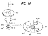
- FIG. 10 explains an eighth embodiment of the present invention.
- a laser beam 101 of Gaussian intensity distribution emitted from an unrepresented laser light source (for example, He-Ne laser) enters an optical element 102 having beam splitting function.
- the optical element 102 is shaped as a thin cylinder whose one of faces is obliquely scraped off from the center toward a condenser lens 103 to form triangular cone.
- the incident laser beam is split into three beams, which are focused by the condenser lens 103 as three beams 101-1, 101-2, 101-3 on a focal plane 104.
- the fine particle 105 has a lower refractive index than in the surrounding medium, or reflects or absorbs the light so that the radiation pressure functions as a repulsive force.
- the fine particle 105 in a position surrounded by the focal positions of three laser beams 101-1, 101-2, 101-3, cannot move from this position, because even if the particle 105 is intended to be moved outside, it is pushed back since the radiation pressures of the laser beams function as repulsive forces. Therefore, the fine particle is trapped in such position surrounded by the laser beams.
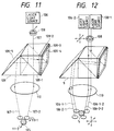
- Fig. 11 is a schematic view of a ninth embodiment of the present invention, in which the fine particles can be transported by the movement of a laser beam.
- a laser beam emitted from a laser light source 106 enters, through an optical pickup 108, a polarization light conversion element 109 having light splitting function, which is detailedly disclosed in Japanese Patent Laid-Open Application No. 3-191318.
- the laser beam 7 entering the polarization light conversion element 109 is separated by a polarization beam splitter 109-1 into S-wave beam (reflected) and P-wave beam (transmitted).
- the reflected S-beam is subjected to a slight bending of the optical axis by a wedge-shaped optical element 109-2, then transmitted by a ⁇ /4-plate 109-3, reflected by a mirror 109-4 and again transmitted by the ⁇ /4-plate 109-3, whereby it is converted into P-wave beam by a phase change of ⁇ /2.
- This P-wave beam is transmitted by the beam splitter 109-1, then reflected by a mirror 109-5 and emerges from the lower face of the element 109.
- the P-wave beam from the incident laser beam 107 and transmitted by the beam splitter 109-1 emerges from the lower face of the element 109.
- These two emerging light beams are focused by a lens 110 as two beams 107-1, 107-2 on a focal plane.
- Fig. 12 schematically shows a tenth embodiment of the present invention, in which same components as those in Fig. 11 are represented by same numbers.
- This embodiment is different from the configuration shown in Fig. 11 in a point that two laser light sources are used to form four beams around the fine particle.
- Two laser light sources 106-1, 106-2 are positioned as illustrated, and four laser beams 106-1-1, 106-1-2, 106-2-1, 106-2-2 are obtained by an optical system similar to that in Fig. 11.
- a fine particle 105 is trapped by these laser beams.
- the fine particle 105 in the present embodiment is trapped by the laser beams in the surrounding four positions, it can be transported in an arbitrary three-dimensional direction by a movement of the optical pickup 108 in an arbitrary direction along the optical axis or perpendicular thereto, thereby three dimensionally moving the focal positions of the laser beams. Also, the fine particle may be trapped or released arbitrarily, by the on-off control of two laser light sources 106-1, 106-2.
- the present embodiment can move two fine particles individually, so that, for example, two fine particles can be attached each other and fused.
- an optical element 112 shaped as a quadrangular cone at a side as shown in Fig. 13, and the optical system is constructed similar to that in Fig. 10. Also, at the light source side on the optical axis, there is provided an optical pickup 108 which can be axially moved. Another similar optical system is symmetrically positioned on the optical axis as shown in Fig. 13, whereby two fine particles can be independently trapped and moved on the same optical axis.
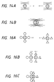
- Figs. 14A and 14B show the mode of such movement. Two fine particles are mutually attached and fused by transferring from a state in Fig. 14A to a state in Fig. 14B.
- an optical shutter 111 divided into four sectors is provided, as shown in Fig. 15, in front of a four-sectored optical element 112.
- the optical shutter 111 is a PLZT optical shutter, and has a circular shape split into four sectors, respectively, so as to correspond to the four faces of the quadrangular cone. It can independently turn on and off four beams on the focal plane.
- Two optical system of such structure are arranged side by side, as shown in Fig. 15.
- Each optical pickup 108 is rendered movable in a plane perpendicular to the optical axis.
- Figs. 16A to 16C show the time-sequential control in the case of attaching of two fine particles.
- Fig. 16A In a state shown in Fig. 16A, four beams are turned on around each particle and are so moved that the two particles approach each other.
- the optical shutters 111 are so controlled as to turn off only a laser beam closest to the opposite particle, as shown in Fig. 16B.
- the two fine particles can be stably attached, as shown in Fig. 16C.
Abstract
Description
- The present invention relates to a technology for manipulating movement of particles in a medium.
- Sheath flow method is already well known for transporting fine particles dispersed in a medium such as liquid, in linear array one by one. In this method, at the center of a high-speed sheath liquid flow, there is formed a very fine flow of liquid in which fine particles such as blood cells, viruses, microorganisms or carrier particles (such as latex particles or ceramic particles) are suspended, whereby the fine particles are separated one by one transported in linear array. Such sheath flow method is applied to so-called flow cytometry which is used for counting the number of such fine particles by optical or electrical method or for identifying the sort or property of such particles by statistical processing of a number of thus obtained data.
- On the other hand, for classifying the fine particles by size or specific gravity thereof, there are known methods utilizing the centrifugal force or the sieving means such as meshes or gels. These methods are applied to classify copying toner or other industrial particles, or to separate microorganisms, cells or the like.
- Apart from these technologies, it is already known that, when fine particles are irradiated with a light beam having intensity gradient such as Gaussian laser beam, the particles are subjected to scattering and gradient forces of radiation pressure so that the fine particles are moved in the direction of irradiation by an axial force and are trapped in the light beam by a radial force. This is a technology called optical trapping, disclosed, for example, in Japanese Patent Laid-Open Application Nos. 2-91545 and 3-223645 and in U.S. Patent No. 3,808,550. Also, U.S. Patent No. 4,887,721 discloses a method of switching two crossing laser beams, thereby transporting the fine particles to a predetermined position by laser optical pressure.
- In consideration of the foregoing, the present invention is to provide a novel method for manipulating particles in a medium. A more specific object of the present invention is to provide novel method and apparatus for continuously transporting particles in an array with a desired interval. Another more specific object of the present invention is to provide novel method and apparatus for separating particles different in size or in refractive index.
-
- Fig. 1 is a view showing the configuration of an apparatus constituting a first embodiment of the present invention;
- Fig. 2 is a view showing a part of the configuration of an apparatus of a second embodiment;
- Fig. 3 is a view showing the configuration of an apparatus of a third embodiment;
- Figs. 4A to 4E are views showing the mode of function of micropump;
- Fig. 5 is a view showing the configuration of an apparatus of a fourth embodiment;
- Fig. 6 is a view showing the configuration of a measuring system in the apparatus shown in Fig. 5;
- Fig. 7 is a view showing the configuration of an apparatus of a fifth embodiment;
- Fig. 8 is a schematic view of a sixth embodiment;
- Fig. 9 is a schematic view of a seventh embodiment;
- Fig. 10 is a schematic view of an eighth embodiment;
- Fig. 11 is a schematic view of a ninth embodiment;
- Fig. 12 is a schematic view of a tenth embodiment;
- Fig. 13 is a schematic view of an eleventh embodiment;
- Figs. 14A and 14B are schematic views of the eleventh embodiment;
- Fig. 15 is a schematic view of a twelfth embodiment; and
- Figs. 16A to 16C are schematic views of the twelfth embodiment.
- Fig. 1 is a view showing the configuration of an apparatus constituting a first embodiment of the present invention, wherein a
supply container 1 contains therein dispersion of fine particles, consisting of a plurality of fine particles (for example, blood cells, viruses, microorganisms, bioparticles such as DNA or RNA, carrier particles or industrial particles) and dispersion medium. The fine particles and the dispersion medium have comparable specific gravities. In the embodiment the fine particles are latex particles of a given size while the dispersion medium is water. Thesupply container 1 is connected to aflow path 2, which is provided with aflow cell 3 of quartz glass in the middle and connected to adischarge container 9. Avacuum pump 10 and avalve 11 are connected to thedischarge container 9. Thevaccum pump 10 is constantly operated to generate a low pressure in thedischarge container 9, thereby creating a flow of particle dispersion of a constant velocity in theflow path 2. Thefine particles 4 in the dispersion medium move together with the flow. The internal diameter of theflow path 2 has to be larger than the diameter of the largest particle, but preferably does not exceed twice of the diameter of the largest particle, since an excessively large internal diameter increases the possibility of simultaneous flowing of plural particles. - A
light source 5, positioned above theflow cell 3, generates a light beam of a predetermined intensity gradient for optical trapping, and is so selected that the wavelength thereof is in a low optical absorption band of the particles. In the present embodiment there is employed a TEM₀₀ mode of YAG laser to generate a Gaussian beam, but there may also be employed various lasers such as solid-state laser, gas laser or semiconductor laser, or light sources not limited to laser, capable of generating light having intensity gradient. The light beam emitted by thelight source 5 is focused by alens system 6 to aposition 8 in the flow path in theflow cell 3. A control means 7 controls thelight source 5 itself or light control means (such as a shutter or a light modulating element) separate from thelight source 5, thereby effecting on-off control or intensity modulation of the light irradiation on theirradiation position 8. The control means 7 also sends instruction to thevacuum pump 10. At a downstream side of theirradiation position 8 in theflow cell 3, there is provided particle measuring means 13 utilizing, for example, optical, electrical, magnetic or acoustooptical method. - When the fine particle passes the
irradiation position 8 while the light beam is focused thereon, the fine particle is subjected to two forces, namely, an axial force toward the irradiating direction of the light beam, and a radial force to confine the particle in the optical axis. Each of the forces depends on the intensity of the laser beam and the intensity distribution along the optical axis, namely, degree of condensation by the lens and the intensity distribution in a direction perpendicular to the optical axis. They also depend on the refractive index and absorbance (reflectance) of the particle, and on the particle size. By means of the radial force, the fine particle may be stopped by trapping at theirradiation position 8, or the moving velocity of the particle may be temporarily reduced close to zero. The fine particle is not subjected to such forces when the light irradiation is not conducted, and moves together with the flow of the dispersion medium. Consequently, the irradiation of the light beam is repeated by turning on and off at a constant interval under the control of the control means (for example, the light beam on for 1 second and off for 0.1 seconds), whereby gate function with constant period can be applied to the moving fine particles. Thus, the fine particles can be moved with a desired constant spacing in the flow path behind the irradiatingposition 8. - More specifically, if the concentration of the fine particles in the dispersion medium is high or if the flow velocity is large, the fine particles move in succession from the
supply container 1 to theirradiating position 8 as shown in Fig. 1. In such condition, the period of off-irradiation (in which the particle can pass) is made shorter than the period of on-irradiation (trapping period), so that plural particles do not pass through the irradiating position at a time. On the other hand, in the case contrary to the above-mentioned condition, there is once conducted a trapping for a long time to accumulate plural particles in front of the trapping position, and then the beam is turned on and off as explained above, thereby transferring the particles at a constant spacing. - Also, since the flow velocity of the dispersion medium is always constant, the spacing of the fine particles in movement may be arbitrarily varied by a variation in the cycle time of the light irradiation. In the condition of the off-irradiation, the irradiating light intensity need not necessarily be brought to zero, but may be reduced to a level not causing the particle trapping.
- It is also possible to discriminate whether the fine particle is trapped at the
irradiation position 8, by monitoring the light amount with a photosensor system positioned opposite to thelight source 5 across theflow cell 3. Also, more reliable control is possible by determining the timing of irradiation, based on the monitoring. - In the case the fine particles are of a lower refractive index than that of the surrounding medium or are reflecting or absorbing the light, the trapping may be conducted by methods explained in eighth and subsequent embodiments.
- Fig. 2 illustrates the configuration of a part of the apparatus of a second embodiment of the present invention, which is a partial modification of the embodiment shown in Fig. 1 and in which non-illustrated components are the same as those in Fig. 1.
- In Fig. 2, the
flow path 2 in aflow cell 12 is bent in key-shape, and the light for optically trapping is irradiated on the flow path in front of the bent portion, in a direction along the flow path. In contrast to the foregoing embodiment in which the light irradiation is made laterally to the flow of the fine particles to trap the particle by the radial force generated by the light irradiation, the present embodiment effects the light irradiation in a direction opposite to the flow of the fine particles, thereby trapping the particle by both the axial and radial forces. - In the case the fine particles are of a lower refractive index than the surrounding medium, or are reflecting or absorbing the light, the trapping may be achieved by methods explained in eighth and subsequent embodiments.
- Fig. 3 shows the configuration of an apparatus constituting a third embodiment of the present invention. A
supply container 20 contains particle dispersion in which a number of fine particles float in a dispersion medium. In thesupply container 20 there is immersed an end of asilicone tube 21, of which the other end is connected to aflow cell 22 of quartz glass. Theflow cell 22 is in turn connected to asilicone tube 23, of which the other end is connected to anozzle 24 equipped with amicropump 25, to be explained below. - As means for forming a flow of the dispersion medium there is employed a pump, which can be exemplified by a vacuum pump for sucking the dispersion medium from the side of the discharge container, a pressure pump for pressurizing the dispersion medium from the side of the supply container, or a feed pump having a liquid feeding mechanism. Although the vacuum pump is employed in the first embodiment, the present embodiment employs a micropump constituting a feed pump. More specifically, the micropump includes a heat-generating element provided. When a pulse voltage is given to the heat-generating element, the liquid heated by the generated heat is gasified instantaneously to generate a bubble, and liquid drops are discharged from the
nozzle 24 by a pressure generated by the impact due to expansion or contraction of the bubble. The particle dispersion is sucked in toward the nozzle, corresponding to the amount of such discharge. A feeding action on the particle dispersion is obtained by effecting the discharge in consecutive manner with a high frequency to form a flow in theflow cell 22. The fine particles move together with the flow. - Figs. 4A to 4E illustrate the mode of liquid droplet discharged by bubble generation. When the heat-generating element is heated instantaneously by a pulse voltage in an initial state shown in Fig. 4A, the liquid in the vicinity of the element is gasified to generate a bubble as shown in Fig. 4B. Then, due to a volume expansion corresponding to the gasification, the liquid in the vicinity of the nozzle aperture is pushed out from the aperture as shown in Fig. 4C. The bubble originally expanding starts to contract by cooling as shown in Fig. 4D, and the liquid pushed out from the aperture forms a liquid droplet and flies in the air as shown in Fig. 4E, because of the volume contraction. The liquid is replenished by capillary phenomena, corresponding to the discharged volume, whereby the initial state shown in Fig. 4A is restored. The basic principle of the liquid droplet discharging by bubble formation is detailedly described, for example, in U.S. Patent Nos. 4,732,129 and 4,740,796.
- As another embodiment of the micropump, it is also possible to replace the heat-generating element with a piezoelectric element and to apply an electric pulse thereto, thereby emitting a liquid droplet by a pressure generated by the impact due to volume change of the piezoelectric element. In such case there is preferred a cylindrical piezoelement which is so provided as to surround the flow path.
- The liquid feeding ability of the micropump can be selected by the voltage and frequency of the electric pulse given to the heat-generating element or the piezoelectric element. In the present embodiment the voltage and frequency supplied to the
micropump 25 are so selected as to obtain a flow of the velocity in the order of 200 µm/sec. in the flow path of theflow cell 22. - Again referring to Fig. 3, a
light source 26 is composed of a YAG laser (1064 nm) for providing the fine particle with axial and radial forces, and the light for trapping the particle is condensed by alens system 27 onto the flow path in theflow cell 22. Anotherlight source 28 is composed of an Ar⁺ laser (488 nm) for measuring the optical characteristics of the fine particle, and the light for particle measurement is focused by alens system 29 onto the flow path in theflow cell 22. The light emitted from the fine particle irradiated by thelens system 29 is collected by alens system 30 and received by a photodetector 31 (photomultiplier or photodiode). A control means 32 effects the control of thelight sources photodetector 31, and the driving of themicropump 25. - When the
light source 26 is turned on and the light thereof is focused on the flow path, the fine particles moving in the flow path can be trapped against the flow. When the light source is turned off, the trapping is released and the fine particle moves again together with the flow. It is therefore possible, as in the foregoing embodiments, to control the spacing of the fine particles separately flowing one by one in the flow path, by turning on and off the irradiation of thelight source 26 with a suitable interval corresponding to the flow velocity and the concentration of the fine particles, under the control of the control means 32. The fine particles flowing in such array pass the irradiation position of thelight source 28 in succession, and the light emitted from each particle (scattered, transmitted or fluorescent light) upon such passing is detected by thephotodetector 31. The detected data are fetched by the control means 32, which effects the analysis such as the identification of sort and property of the particles, based on the data obtained from a plurality of particles. - In the case the fine particles are of a lower refractive index than the surrounding medium, or are reflecting or absorbing the light, the trapping may be made by methods of eighth and subsequent embodiments to be explained later.
- Fig. 5 illustrates the configuration of an apparatus constituting a fourth embodiment of the present invention, in which the particle movement is achieved by the radiation pressure instead of the pump.
- Referring to Fig. 5, in a
cell 40 of a transparent material such as glass or plastic, there are formed afirst resorvoir 41 and asecond reservoir 42, which are mutually connected bypaths paths - There are provided three independent
laser light sources lens systems laser light sources lens systems path 43 crosses the second laser beam irradiating thepath 44, and, at the crossing point, the radiation pressure of the second light beam is set larger than that of the first laser beam, so that the fine particles moved by the radiation pressure are smoothly moved from thepath 43 to thepath 44. - On the other hand, the laser beam emitted from the
laser light source 49 is converted, by thelens system 50, into a converging light beam (called third laser beam) condensed on thepath 43, thereby providing the fine particle with a radial force for particle trapping, against the axial force of the first laser beam from thelaser light source 45. In the present embodiment the third laser beam is irradiated on a position in front of the crossing point of the first and second light beams, but the third light beam may also be irradiated on the crossing point of the first and second light beams. - In the
path 44 there is provided a measuring system as shown in Fig. 6, which is a view seen from the left-hand side of Fig. 5. The measured system includes, for effecting measuring light irradiation on the individually moving fine particles, a light source 52 (such as laser light source, halogen light source or xenon light source) and alens system 53. Among the lights emitted from the irradiated fine particle, the scattered light is detected by alens 54 and aphotodetector 5 while the fluorescent light is detected by alens 56 and aphotodetector 57. The outputs from thephotodetectors - When a fine particle dispersed in the
first reservoir 41 enters within the first laser beam, it is cought in the light beam and is transported in a direction A. It is thus guided to thepath 43 and reach the focused position of the third laser beam. When the irradiation of the third laser beam is turned on, the fine particle stops by trapping with the light beam. When the irradiation is turned off, the trapping force is removed, whereby the fine particle starts to move again in the direction A, under the axial force by the first laser beam. When the fine particle reaches the crossing point of the first and second laser beams, it starts to move in a direction B under the stronger radiation pressure of the second laser beam, and reaches thesecond reservoir 42. - As in the foregoing embodiments, a control means 51 suitably selects the on-off interval of the third laser, whereby the particles move in array with a predetermined spacing in the
path 44 without mutual adhesion or overlapping of the particles. - Fig. 7 shows the configuration of an apparatus constituting a fifth embodiment, which is simplified from the configuration of the foregoing fourth embodiment. In the present embodiment, instead of the independent laser light sources in the foregoing embodiment, the light from a laser light source is split by a beam splitter into three laser beams. Also, no path is provided for guiding the moving particles.
- In a
container 60 there is sealed the particle dispersion similar to that in the foregoing embodiments. Alight source 61 is composed of a YAG laser. Among the laser beams emitted therefrom, a beam transmitted by abeam splitter 62 and alens 67 and split by abeam splitter 63 is further reflected bymirrors beam splitter 62,lens 67 andbeam splitter 63 is introduced into thecontainer 60 as the second laser beam (direction B). Also, a laser beam emitted from thelight source 61 and split by thebeam splitter 62 is reflected by amirror 64, then transmitted by ashutter 68 and focused by alens 69 as the third laser beam onto the optical axis of the first laser beam. The positional relationship of the first, second and third laser beams is similar to that in the foregoing fourth embodiment. Also, there is provided a measuring system similar to that shown in Fig. 6 in order to optically measure the fine particles moved in array in the direction B. - The spacing in transportation of the particles is determined by on-off control of the irradiation of the third laser beam for optical trapping, through switching of the shutter 68 (liquid crystal shutter or mechanical shutter) under the control of a control means 70. The shutter may also be replaced by an optical modulation element, such as an acoustooptical element.
- Generally, assuming that intensity and the wavelength of the light for optical trapping are constant, the trapping force acting on the particle becomes larger, as the particle size increases or as the difference in refractive index between the particle and the dispersion medium becomes larger (in the case the refractive index of the particle is larger than that of the dispersion medium). Also, in the case of the same particle size, the trapping force acting thereon becomes larger, as the light intensity for optical trapping becomes stronger, or as the focused spot size of the light becomes smaller, or as the wavelength of the light becomes shorter. Consequently, the particles may be trapped or not depending on the size or the refractive index thereof. In the following there will be explained an embodiment for separating the particles, utilizing the above-explained phenomenon, according to the size or the refractive index.
- Fig. 8 illustrates the configuration of an apparatus constituting a sixth embodiment, wherein a
specimen container 85 contains liquid consisting of at least two different particles and a dispersion medium (for example, water). The fine particles and dispersion medium have comparable specific gravities. In the present embodiment, the different particles are defined to be different in (1) size, (2) refractive index, or (3) size and refractive index. Examples of the fine particles include cells, viruses, microorganisms, bioparticles such as DNA or RNA, carrier particles and industrial particles. - A
container 80 contains the dispersion medium (for example, water). In thespecimen container 85 and thecontainer 80, there are respectively insertedtubes flow path 2 through ajoint valve 82. Theflow path 2 includes aflow cell 3 of quartz glass in the middle, and is connected to adischarge chamber 81. Thechamber 81 can be maintained in a hermetically sealed condition by closing avalve 11. In thedischarge chamber 81 there is provided afraction container 88, into which the liquid having passed theflow path 2 is charged. In the above-explained configuration, the interior of thedischarge chamber 81 is maintained at a low pressure by the activation of avacuum pump 10, thereby forming a flow of the dispersion medium including the fine particles, in theflow path 2. At a downstream position of the irradiation position in theflow cell 3, there is provided particle measuring means 13 utilizing, for example, an optical, electrical, magnetic or acoustooptical method. - In the apparatus of the present embodiment, in order to set a threshold value for separating the particles according to the size or the refractive index thereof, the intensity of the trapping light beam emitting from a
light source 5 and irradiated on theposition 8, is rendered adjustable. This adjustment can be achieved, for example, by (1) controlling the emission intensity of thelight source 5, (2) regulating the irradiating light amount by placing a modulation element or a filter in the optical path, or (3) regulating the practical light amount by varying the focused spot size at the irradiation position through adjustment of alens 6. - The functions of the above-explained apparatus are as follows. At first, the
joint valve 82 is connected to thetube 86 to introduce a small amount of the particle dispersion from thespecimen container 85 into theflow path 2. Then, thejoint valve 82 is switched to thetube 87, thereby introducing the dispersion medium only. Thus, the fine particles flow in theflow cell 3, together with the flow of the dispersion medium. In theirradiation position 8, a larger trapping force acts on a particle larger in size or in refractive index. In a control means 7, the irradiation intensity is set in advance by the above-mentioned method at such level than the particles large in size (or in refractive index) are trapped but those small in size (or in refractive index) are not trapped. Consequently, the particles larger in size (or in refractive index) alone are trapped at theirradiation position 8, while the smaller particles pass this position. Thus, the smaller particles alone are selectively transmitted, then measured by the measuring means 13 and are charged in thefraction container 88. Thereafter, thefraction container 88 may be recovered, and the particles trapped at the irradiation position may be measured by flowing one by one through the control of the irradiation timing. - In the present embodiment, the threshold value for particle separation is set by adjusting the intensity of the irradiating light, but the threshold value may be varied by the wavelength of the irradiating light instead of the intensity.
- In the foregoing embodiment shown in Fig. 8, the particle separation is executed by trapping the particles completely at the irradiation position, but the separation may also be achieved by varying the moving velocity in such a manner that suitable braking force is applied to the particles according to the kind of the particle without complete trapping. In the following there will be explained such embodiment.
- Fig. 9 illustrates the configuration of an apparatus constituting a seventh embodiment of the present invention, wherein same components as those in Fig. 8 are represented by same numbers. The light emitted from the
light source 5 is reflected by amirror 91, and then separated into five beams by fourhalf mirrors mirror 92. The beams are respectively focused by lenses onto five positions along the flow in theflow cell 3. In the present embodiment, the reflectance/transmittance of the half mirrors 90a to 90d are so selected that the irradiation intensities are mutually equal at the irradiation positions. The irradiation intensity is maintained at such level as to not cause complete trapping of the particles. If necessary, the irradiation intensities may be made different at the irradiation positions. Also, the irradiation intensity may be made variable in order to vary the braking force. - In the above-explained configuration, when the fine particles of plural kinds different in the size or refractive index, a particle receiving a larger trapping force becomes slower in the moving velocity, receiving a larger braking force at each irradiation position. Consequently, the particles receiving smaller braking force flow faster, and the particle separation can be achieved.
- In the following there will be explained a method of trapping the fine particles in the case they are lower in the refractive index than in the surrounding medium, or they reflect or absorb the light. Fig. 10 explains an eighth embodiment of the present invention. A
laser beam 101 of Gaussian intensity distribution, emitted from an unrepresented laser light source (for example, He-Ne laser) enters anoptical element 102 having beam splitting function. Theoptical element 102 is shaped as a thin cylinder whose one of faces is obliquely scraped off from the center toward acondenser lens 103 to form triangular cone. By the function of theoptical element 102, the incident laser beam is split into three beams, which are focused by thecondenser lens 103 as three beams 101-1, 101-2, 101-3 on afocal plane 104. - In the right-hand side of Fig. 10 there is shown a magnified view of the
focal plane 104. Thefine particle 105 has a lower refractive index than in the surrounding medium, or reflects or absorbs the light so that the radiation pressure functions as a repulsive force. Thefine particle 105 in a position surrounded by the focal positions of three laser beams 101-1, 101-2, 101-3, cannot move from this position, because even if theparticle 105 is intended to be moved outside, it is pushed back since the radiation pressures of the laser beams function as repulsive forces. Therefore, the fine particle is trapped in such position surrounded by the laser beams. - Fig. 11 is a schematic view of a ninth embodiment of the present invention, in which the fine particles can be transported by the movement of a laser beam. A laser beam emitted from a
laser light source 106 enters, through anoptical pickup 108, a polarizationlight conversion element 109 having light splitting function, which is detailedly disclosed in Japanese Patent Laid-Open Application No. 3-191318. - The
laser beam 7 entering the polarizationlight conversion element 109 is separated by a polarization beam splitter 109-1 into S-wave beam (reflected) and P-wave beam (transmitted). The reflected S-beam is subjected to a slight bending of the optical axis by a wedge-shaped optical element 109-2, then transmitted by a λ/4-plate 109-3, reflected by a mirror 109-4 and again transmitted by the λ/4-plate 109-3, whereby it is converted into P-wave beam by a phase change of λ/2. This P-wave beam is transmitted by the beam splitter 109-1, then reflected by a mirror 109-5 and emerges from the lower face of theelement 109. On the other hand, the P-wave beam from theincident laser beam 107 and transmitted by the beam splitter 109-1 emerges from the lower face of theelement 109. These two emerging light beams are focused by alens 110 as two beams 107-1, 107-2 on a focal plane. - In such optical configuration, when the
optical pickup 108 is moved by an unrepresented driving mechanism in a direction of arrow perpendicular to the optical axis, the two laser beams 107-1, 107-2 move as indicated by an arrow 111-1. Thus, afine particle 105 is pushed by the repulsive force of the radiation pressure of the laser beams and can be moved as indicated by an arrow 111-2. - Fig. 12 schematically shows a tenth embodiment of the present invention, in which same components as those in Fig. 11 are represented by same numbers. This embodiment is different from the configuration shown in Fig. 11 in a point that two laser light sources are used to form four beams around the fine particle. Two laser light sources 106-1, 106-2 are positioned as illustrated, and four laser beams 106-1-1, 106-1-2, 106-2-1, 106-2-2 are obtained by an optical system similar to that in Fig. 11. A
fine particle 105 is trapped by these laser beams. - As the
fine particle 105 in the present embodiment is trapped by the laser beams in the surrounding four positions, it can be transported in an arbitrary three-dimensional direction by a movement of theoptical pickup 108 in an arbitrary direction along the optical axis or perpendicular thereto, thereby three dimensionally moving the focal positions of the laser beams. Also, the fine particle may be trapped or released arbitrarily, by the on-off control of two laser light sources 106-1, 106-2. - In the following explained is an eleventh embodiment of the present invention. In contrast to the embodiments shown in Figs. 10 to 12 which deal with one fine particle, the present embodiment can move two fine particles individually, so that, for example, two fine particles can be attached each other and fused.
- In order to split a laser beam into four beams, there is employed an optical element 112 shaped as a quadrangular cone at a side as shown in Fig. 13, and the optical system is constructed similar to that in Fig. 10. Also, at the light source side on the optical axis, there is provided an
optical pickup 108 which can be axially moved. Another similar optical system is symmetrically positioned on the optical axis as shown in Fig. 13, whereby two fine particles can be independently trapped and moved on the same optical axis. - In such configuration, when the two
optical pickups 108 are moved in a direction of the optical axis, the focal positions of the laser beams can be axially moved, thereby moving the fine particles trapped therein, respectively. Figs. 14A and 14B show the mode of such movement. Two fine particles are mutually attached and fused by transferring from a state in Fig. 14A to a state in Fig. 14B. - In a twelfth embodiment of the present invention explained in the following, an
optical shutter 111 divided into four sectors is provided, as shown in Fig. 15, in front of a four-sectored optical element 112. Theoptical shutter 111 is a PLZT optical shutter, and has a circular shape split into four sectors, respectively, so as to correspond to the four faces of the quadrangular cone. It can independently turn on and off four beams on the focal plane. Two optical system of such structure are arranged side by side, as shown in Fig. 15. Eachoptical pickup 108 is rendered movable in a plane perpendicular to the optical axis. - Figs. 16A to 16C show the time-sequential control in the case of attaching of two fine particles. In a state shown in Fig. 16A, four beams are turned on around each particle and are so moved that the two particles approach each other. When the two particles are close to each other, the
optical shutters 111 are so controlled as to turn off only a laser beam closest to the opposite particle, as shown in Fig. 16B. Thus, the two fine particles can be stably attached, as shown in Fig. 16C.
Claims (7)
- A particle manipulating method, comprising controlling a movement of a moving particle by optically braking the moving particle.
- A method according to claim 1, comprising controlling a movement spacing of particles by optically braking the particles.
- A method according to claim 1, comprising separating particles by optically braking the particles.
- A particle manipulating apparatus comprising:
means for moving particles; and
means for irradiating toward the moving particles a light for optical braking thereof. - A particle measuring apparatus comprising:
means for moving particles;
means for irradiating toward moving particles a light for optical braking thereof; and
means for measuring said moving particles. - A particle manipulating method comprising optically trapping a particle by focusing plural light beams each having an intensity distribution around the particle to which radiation pressure acts as a repulsive force.
- A method according to claim 6, comprising transporting the trapped particle by simultaneously moving focal positions of said plural light beams.
Applications Claiming Priority (6)
| Application Number | Priority Date | Filing Date | Title |
|---|---|---|---|
| JP3344192 | 1992-02-20 | ||
| JP33441/92 | 1992-02-20 | ||
| JP36262/92 | 1992-02-24 | ||
| JP3626292A JP2714305B2 (en) | 1992-02-24 | 1992-02-24 | Optical trap method |
| JP4344578A JP2756397B2 (en) | 1992-02-20 | 1992-12-24 | Particle operation method and apparatus, and measurement apparatus using the same |
| JP344578/92 | 1992-12-24 |
Publications (3)
| Publication Number | Publication Date |
|---|---|
| EP0556748A2 true EP0556748A2 (en) | 1993-08-25 |
| EP0556748A3 EP0556748A3 (en) | 1995-01-25 |
| EP0556748B1 EP0556748B1 (en) | 1998-10-28 |
Family
ID=27288075
Family Applications (1)
| Application Number | Title | Priority Date | Filing Date |
|---|---|---|---|
| EP93102257A Expired - Lifetime EP0556748B1 (en) | 1992-02-20 | 1993-02-12 | Method and apparatus for particle manipulation, and measuring apparatus utilizing the same |
Country Status (3)
| Country | Link |
|---|---|
| EP (1) | EP0556748B1 (en) |
| AT (1) | ATE172791T1 (en) |
| DE (1) | DE69321748T2 (en) |
Cited By (16)
| Publication number | Priority date | Publication date | Assignee | Title |
|---|---|---|---|---|
| EP0635994A1 (en) * | 1993-07-08 | 1995-01-25 | Canon Kabushiki Kaisha | Method and apparatus for separating particles |
| CN1036093C (en) * | 1994-01-14 | 1997-10-08 | 中国科学院光电技术研究所 | Particle measuring method and particle detecting sensor thereof |
| WO1998039567A1 (en) * | 1997-03-04 | 1998-09-11 | Deutsches Zentrum für Luft- und Raumfahrt e.V. | Process and device for moving particles, and use of said process and device |
| WO1999011373A2 (en) * | 1997-08-28 | 1999-03-11 | Hunter Ian W | Apparatus and methods for droplet microchemistry |
| WO2001031315A1 (en) * | 1999-10-29 | 2001-05-03 | Evotec Oai Ag | Method and device for particle separation |
| WO2002039104A1 (en) * | 2000-11-13 | 2002-05-16 | Genoptix, Inc. | System and method for separating micro-particles |
| WO2002079721A1 (en) * | 2001-03-29 | 2002-10-10 | Kvassheim Torbjoern | A device for a transparent pipe intended for optical counting and measuring |
| WO2004015399A1 (en) * | 2002-08-07 | 2004-02-19 | Bavarian Nordic A/S | Filling device for capsules, in particular medicament capsules |
| EP1390160A1 (en) * | 2001-04-27 | 2004-02-25 | Genoptix, Inc. | Methods and apparatus for use of optical forces for identification, characterization and/or sorting of particles |
| US6812030B2 (en) | 2001-04-25 | 2004-11-02 | Biotrove, Inc. | System and method for high throughput sample preparation and analysis using column chromatography |
| WO2005094141A1 (en) * | 2004-03-02 | 2005-10-06 | Boston Scientific Limited | Apparatus and method for coating objects using an optical system |
| US7118351B2 (en) | 2002-05-16 | 2006-10-10 | Roche Diagnostics Operations, Inc. | Micropump with heating elements for a pulsed operation |
| US7588725B2 (en) | 2001-04-25 | 2009-09-15 | Biotrove, Inc. | High throughput autosampler |
| US8410426B2 (en) | 2007-11-02 | 2013-04-02 | Agilent Technologies, Inc. | Devices and methods for coupling mass spectrometry devices with chromatography systems |
| US8414774B2 (en) | 2001-04-25 | 2013-04-09 | Agilent Technologies, Inc. | Systems and methods for high-throughput screening of fluidic samples |
| EP4024030A4 (en) * | 2019-08-30 | 2023-09-13 | University Public Corporation Osaka | Detection method for substance to be detected and detection system for substance to be detected |
Families Citing this family (20)
| Publication number | Priority date | Publication date | Assignee | Title |
|---|---|---|---|---|
| CA2279574C (en) | 1997-01-31 | 2007-07-24 | The Horticulture & Food Research Institute Of New Zealand Ltd. | Optical apparatus |
| US6149867A (en) | 1997-12-31 | 2000-11-21 | Xy, Inc. | Sheath fluids and collection systems for sex-specific cytometer sorting of sperm |
| US7208265B1 (en) | 1999-11-24 | 2007-04-24 | Xy, Inc. | Method of cryopreserving selected sperm cells |
| US6833542B2 (en) | 2000-11-13 | 2004-12-21 | Genoptix, Inc. | Method for sorting particles |
| US6784420B2 (en) | 2000-11-13 | 2004-08-31 | Genoptix, Inc. | Method of separating particles using an optical gradient |
| US6744038B2 (en) | 2000-11-13 | 2004-06-01 | Genoptix, Inc. | Methods of separating particles using an optical gradient |
| US6778724B2 (en) | 2000-11-28 | 2004-08-17 | The Regents Of The University Of California | Optical switching and sorting of biological samples and microparticles transported in a micro-fluidic device, including integrated bio-chip devices |
| US7713687B2 (en) | 2000-11-29 | 2010-05-11 | Xy, Inc. | System to separate frozen-thawed spermatozoa into x-chromosome bearing and y-chromosome bearing populations |
| CA2468774C (en) | 2000-11-29 | 2015-06-30 | George E. Seidel | System for in-vitro fertilization with spermatozoa separated into x-chromosome and y-chromosome bearing populations |
| US8486618B2 (en) | 2002-08-01 | 2013-07-16 | Xy, Llc | Heterogeneous inseminate system |
| EP2275533B9 (en) | 2002-08-01 | 2016-10-19 | Xy, Llc | Method of assessing sperm cells |
| US7855078B2 (en) | 2002-08-15 | 2010-12-21 | Xy, Llc | High resolution flow cytometer |
| US7169548B2 (en) | 2002-09-13 | 2007-01-30 | Xy, Inc. | Sperm cell processing and preservation systems |
| DK2959774T3 (en) | 2003-03-28 | 2019-05-13 | Inguran Llc | PROCEDURE FOR CRYCONSERVATION OF SEAT CELLS |
| WO2004104178A2 (en) | 2003-05-15 | 2004-12-02 | Xy, Inc. | Efficient haploid cell sorting for flow cytometer systems |
| CA2536360C (en) | 2003-08-28 | 2013-08-06 | Celula, Inc. | Methods and apparatus for sorting cells using an optical switch in a microfluidic channel network |
| BRPI0509485A (en) | 2004-03-29 | 2007-09-11 | Monsanto Technology Llc | sperm suspensions for use in insemination |
| EP1769067A2 (en) | 2004-07-22 | 2007-04-04 | Monsanto Technology LLC | Process for enriching a population of sperm cells |
| DE102006018332B4 (en) | 2006-04-19 | 2023-07-13 | Mykhaylo Ponizovskiy | Method and device for fractionating blood cells |
| DE102008060332B4 (en) * | 2008-12-03 | 2013-01-10 | Albert-Ludwigs-Universität Freiburg | Method for sorting at least one particle with a microfluidic sorting device with optical tweezers |
Citations (2)
| Publication number | Priority date | Publication date | Assignee | Title |
|---|---|---|---|---|
| US3808550A (en) * | 1969-12-15 | 1974-04-30 | Bell Telephone Labor Inc | Apparatuses for trapping and accelerating neutral particles |
| US4887721A (en) * | 1987-11-30 | 1989-12-19 | The United States Of America As Represented By The United States Department Of Energy | Laser particle sorter |
-
1993
- 1993-02-12 AT AT93102257T patent/ATE172791T1/en active
- 1993-02-12 DE DE69321748T patent/DE69321748T2/en not_active Expired - Lifetime
- 1993-02-12 EP EP93102257A patent/EP0556748B1/en not_active Expired - Lifetime
Patent Citations (2)
| Publication number | Priority date | Publication date | Assignee | Title |
|---|---|---|---|---|
| US3808550A (en) * | 1969-12-15 | 1974-04-30 | Bell Telephone Labor Inc | Apparatuses for trapping and accelerating neutral particles |
| US4887721A (en) * | 1987-11-30 | 1989-12-19 | The United States Of America As Represented By The United States Department Of Energy | Laser particle sorter |
Non-Patent Citations (2)
| Title |
|---|
| APPLIED PHYSICS LETTERS, 17 FEB. 1992, USA, VOL. 60, NO. 7, PAGES 807 - 809, ISSN 0003-6951 Sasaki K et al : 'Optical trapping of a metal particle and a water droplet by a scanning laser beam' * |
| JAPANESE JOURNAL OF APPLIED PHYSICS, PART 2 (LETTERS), 15 MAY 1991, JAPAN, VOL. 30, NO. 5B, PAGES L907 - L909, ISSN 0021-4922 Sasaki K et al : 'Laser-scanning micromanipulation and spatial patterning of fine particles' * |
Cited By (28)
| Publication number | Priority date | Publication date | Assignee | Title |
|---|---|---|---|---|
| EP0635994A1 (en) * | 1993-07-08 | 1995-01-25 | Canon Kabushiki Kaisha | Method and apparatus for separating particles |
| US6224732B1 (en) | 1993-07-08 | 2001-05-01 | Canon Kabushiki Kaisha | Method and apparatus for separating particles |
| CN1036093C (en) * | 1994-01-14 | 1997-10-08 | 中国科学院光电技术研究所 | Particle measuring method and particle detecting sensor thereof |
| WO1998039567A1 (en) * | 1997-03-04 | 1998-09-11 | Deutsches Zentrum für Luft- und Raumfahrt e.V. | Process and device for moving particles, and use of said process and device |
| WO1999011373A2 (en) * | 1997-08-28 | 1999-03-11 | Hunter Ian W | Apparatus and methods for droplet microchemistry |
| WO1999011373A3 (en) * | 1997-08-28 | 1999-07-29 | Ian W Hunter | Apparatus and methods for droplet microchemistry |
| US6309600B1 (en) | 1997-08-28 | 2001-10-30 | Biotrove, Inc. | Apparatus for droplet microchemistry |
| WO2001031315A1 (en) * | 1999-10-29 | 2001-05-03 | Evotec Oai Ag | Method and device for particle separation |
| AU2002230696B2 (en) * | 2000-11-13 | 2005-07-21 | Celula, Inc. | System and method for separating micro-particles |
| US6936811B2 (en) | 2000-11-13 | 2005-08-30 | Genoptix, Inc. | Method for separating micro-particles |
| WO2002039104A1 (en) * | 2000-11-13 | 2002-05-16 | Genoptix, Inc. | System and method for separating micro-particles |
| US6965430B2 (en) | 2001-03-29 | 2005-11-15 | Kvassheim Torbjoern | Device for a transparent pipe intended for optical counting and measuring |
| GB2394769B (en) * | 2001-03-29 | 2005-10-12 | Torbjorn Kvassheim | A device for a transparent pipe intended for optical counting and measuring |
| GB2394769A (en) * | 2001-03-29 | 2004-05-05 | Torbjorn Kvassheim | A device for a transparent pipe intended for optical counting and measuring |
| WO2002079721A1 (en) * | 2001-03-29 | 2002-10-10 | Kvassheim Torbjoern | A device for a transparent pipe intended for optical counting and measuring |
| US6812030B2 (en) | 2001-04-25 | 2004-11-02 | Biotrove, Inc. | System and method for high throughput sample preparation and analysis using column chromatography |
| US7588725B2 (en) | 2001-04-25 | 2009-09-15 | Biotrove, Inc. | High throughput autosampler |
| US8414774B2 (en) | 2001-04-25 | 2013-04-09 | Agilent Technologies, Inc. | Systems and methods for high-throughput screening of fluidic samples |
| EP1390160A1 (en) * | 2001-04-27 | 2004-02-25 | Genoptix, Inc. | Methods and apparatus for use of optical forces for identification, characterization and/or sorting of particles |
| AU2002241760B2 (en) * | 2001-04-27 | 2006-08-24 | Celula, Inc. | Methods and apparatus for use of optical forces for identification, characterization and/or sorting of particles |
| EP1390160A4 (en) * | 2001-04-27 | 2008-08-20 | Celula Inc | Methods and apparatus for use of optical forces for identification, characterization and/or sorting of particles |
| US7118351B2 (en) | 2002-05-16 | 2006-10-10 | Roche Diagnostics Operations, Inc. | Micropump with heating elements for a pulsed operation |
| WO2004015399A1 (en) * | 2002-08-07 | 2004-02-19 | Bavarian Nordic A/S | Filling device for capsules, in particular medicament capsules |
| WO2005094141A1 (en) * | 2004-03-02 | 2005-10-06 | Boston Scientific Limited | Apparatus and method for coating objects using an optical system |
| US7425345B2 (en) | 2004-03-02 | 2008-09-16 | Boston Scientific Scimed, Inc. | Apparatus and method for coating objects using an optical system |
| US8410426B2 (en) | 2007-11-02 | 2013-04-02 | Agilent Technologies, Inc. | Devices and methods for coupling mass spectrometry devices with chromatography systems |
| US8677808B2 (en) | 2007-11-02 | 2014-03-25 | Agilent Technologies, Inc. | Sample injection system |
| EP4024030A4 (en) * | 2019-08-30 | 2023-09-13 | University Public Corporation Osaka | Detection method for substance to be detected and detection system for substance to be detected |
Also Published As
| Publication number | Publication date |
|---|---|
| DE69321748D1 (en) | 1998-12-03 |
| EP0556748B1 (en) | 1998-10-28 |
| DE69321748T2 (en) | 1999-06-17 |
| ATE172791T1 (en) | 1998-11-15 |
| EP0556748A3 (en) | 1995-01-25 |
Similar Documents
| Publication | Publication Date | Title |
|---|---|---|
| US5495105A (en) | Method and apparatus for particle manipulation, and measuring apparatus utilizing the same | |
| EP0556748B1 (en) | Method and apparatus for particle manipulation, and measuring apparatus utilizing the same | |
| US5275787A (en) | Apparatus for separating or measuring particles to be examined in a sample fluid | |
| JP5086101B2 (en) | Cell sorting method and apparatus | |
| JP2756397B2 (en) | Particle operation method and apparatus, and measurement apparatus using the same | |
| CA2601739C (en) | Optical manipulation system using a plurality of optical traps | |
| US4887721A (en) | Laser particle sorter | |
| JP6605327B2 (en) | Particle manipulation device with cytometry function | |
| US8717569B2 (en) | Apparatus and method for improved optical detection of particles in fluid | |
| US7880108B2 (en) | Deflection plate | |
| JP2004184217A (en) | Apparatus for obtaining data of biological particle | |
| CN102331396A (en) | Minute particle analyzing device and method | |
| EP0421406B1 (en) | Apparatus and method for separating or measuring particles to be examined in a sample fluid | |
| JPH0526799A (en) | Method for separating particle | |
| KR20090073650A (en) | Microfluidic device for sorting cells using laser ablation | |
| EP4190450A1 (en) | Imaging apparatus for imaging a nozzle section of a droplet dispenser device, dispenser apparatus including the imaging apparatus, and applications thereof | |
| JP7373859B2 (en) | Particle separator and flow cell alignment method | |
| EP4012380A1 (en) | A light excitation and collection device and a method for light excitation and collection | |
| JPH0724311A (en) | Method and apparatus for separation of particle | |
| JPH0838882A (en) | Method and apparatus for fractionating fine particles | |
| JPH0448245A (en) | Particle measuring instrument | |
| Martin et al. | Laser particle sorter |
Legal Events
| Date | Code | Title | Description |
|---|---|---|---|
| PUAI | Public reference made under article 153(3) epc to a published international application that has entered the european phase |
Free format text: ORIGINAL CODE: 0009012 |
|
| AK | Designated contracting states |
Kind code of ref document: A2 Designated state(s): AT BE CH DE DK ES FR GB GR IE IT LI LU NL PT SE |
|
| PUAL | Search report despatched |
Free format text: ORIGINAL CODE: 0009013 |
|
| AK | Designated contracting states |
Kind code of ref document: A3 Designated state(s): AT BE CH DE DK ES FR GB GR IE IT LI LU NL PT SE |
|
| 17P | Request for examination filed |
Effective date: 19950720 |
|
| 17Q | First examination report despatched |
Effective date: 19960202 |
|
| GRAG | Despatch of communication of intention to grant |
Free format text: ORIGINAL CODE: EPIDOS AGRA |
|
| GRAG | Despatch of communication of intention to grant |
Free format text: ORIGINAL CODE: EPIDOS AGRA |
|
| GRAH | Despatch of communication of intention to grant a patent |
Free format text: ORIGINAL CODE: EPIDOS IGRA |
|
| GRAH | Despatch of communication of intention to grant a patent |
Free format text: ORIGINAL CODE: EPIDOS IGRA |
|
| GRAA | (expected) grant |
Free format text: ORIGINAL CODE: 0009210 |
|
| AK | Designated contracting states |
Kind code of ref document: B1 Designated state(s): AT BE CH DE DK ES FR GB GR IE IT LI LU NL PT SE |
|
| PG25 | Lapsed in a contracting state [announced via postgrant information from national office to epo] |
Ref country code: NL Free format text: LAPSE BECAUSE OF FAILURE TO SUBMIT A TRANSLATION OF THE DESCRIPTION OR TO PAY THE FEE WITHIN THE PRESCRIBED TIME-LIMIT Effective date: 19981028 Ref country code: LI Free format text: LAPSE BECAUSE OF FAILURE TO SUBMIT A TRANSLATION OF THE DESCRIPTION OR TO PAY THE FEE WITHIN THE PRESCRIBED TIME-LIMIT Effective date: 19981028 Ref country code: IT Free format text: LAPSE BECAUSE OF FAILURE TO SUBMIT A TRANSLATION OF THE DESCRIPTION OR TO PAY THE FEE WITHIN THE PRE;WARNING: LAPSES OF ITALIAN PATENTS WITH EFFECTIVE DATE BEFORE 2007 MAY HAVE OCCURRED AT ANY TIME BEFORE 2007. THE CORRECT EFFECTIVE DATE MAY BE DIFFERENT FROM THE ONE RECORDED.SCRIBED TIME-LIMIT Effective date: 19981028 Ref country code: GR Free format text: LAPSE BECAUSE OF NON-PAYMENT OF DUE FEES Effective date: 19981028 Ref country code: ES Free format text: THE PATENT HAS BEEN ANNULLED BY A DECISION OF A NATIONAL AUTHORITY Effective date: 19981028 Ref country code: CH Free format text: LAPSE BECAUSE OF FAILURE TO SUBMIT A TRANSLATION OF THE DESCRIPTION OR TO PAY THE FEE WITHIN THE PRESCRIBED TIME-LIMIT Effective date: 19981028 Ref country code: BE Free format text: LAPSE BECAUSE OF FAILURE TO SUBMIT A TRANSLATION OF THE DESCRIPTION OR TO PAY THE FEE WITHIN THE PRESCRIBED TIME-LIMIT Effective date: 19981028 Ref country code: AT Free format text: LAPSE BECAUSE OF FAILURE TO SUBMIT A TRANSLATION OF THE DESCRIPTION OR TO PAY THE FEE WITHIN THE PRESCRIBED TIME-LIMIT Effective date: 19981028 |
|
| REF | Corresponds to: |
Ref document number: 172791 Country of ref document: AT Date of ref document: 19981115 Kind code of ref document: T |
|
| REG | Reference to a national code |
Ref country code: CH Ref legal event code: EP |
|
| REF | Corresponds to: |
Ref document number: 69321748 Country of ref document: DE Date of ref document: 19981203 |
|
| ET | Fr: translation filed | ||
| REG | Reference to a national code |
Ref country code: IE Ref legal event code: FG4D |
|
| PG25 | Lapsed in a contracting state [announced via postgrant information from national office to epo] |
Ref country code: SE Free format text: LAPSE BECAUSE OF FAILURE TO SUBMIT A TRANSLATION OF THE DESCRIPTION OR TO PAY THE FEE WITHIN THE PRESCRIBED TIME-LIMIT Effective date: 19990128 Ref country code: PT Free format text: LAPSE BECAUSE OF FAILURE TO SUBMIT A TRANSLATION OF THE DESCRIPTION OR TO PAY THE FEE WITHIN THE PRESCRIBED TIME-LIMIT Effective date: 19990128 Ref country code: DK Free format text: LAPSE BECAUSE OF FAILURE TO SUBMIT A TRANSLATION OF THE DESCRIPTION OR TO PAY THE FEE WITHIN THE PRESCRIBED TIME-LIMIT Effective date: 19990128 |
|
| PG25 | Lapsed in a contracting state [announced via postgrant information from national office to epo] |
Ref country code: LU Free format text: LAPSE BECAUSE OF NON-PAYMENT OF DUE FEES Effective date: 19990212 Ref country code: IE Free format text: LAPSE BECAUSE OF NON-PAYMENT OF DUE FEES Effective date: 19990212 |
|
| NLV1 | Nl: lapsed or annulled due to failure to fulfill the requirements of art. 29p and 29m of the patents act | ||
| REG | Reference to a national code |
Ref country code: CH Ref legal event code: PL |
|
| PLBE | No opposition filed within time limit |
Free format text: ORIGINAL CODE: 0009261 |
|
| STAA | Information on the status of an ep patent application or granted ep patent |
Free format text: STATUS: NO OPPOSITION FILED WITHIN TIME LIMIT |
|
| 26N | No opposition filed | ||
| REG | Reference to a national code |
Ref country code: IE Ref legal event code: MM4A |
|
| REG | Reference to a national code |
Ref country code: GB Ref legal event code: IF02 |
|
| PGFP | Annual fee paid to national office [announced via postgrant information from national office to epo] |
Ref country code: DE Payment date: 20110228 Year of fee payment: 19 Ref country code: FR Payment date: 20110315 Year of fee payment: 19 |
|
| PGFP | Annual fee paid to national office [announced via postgrant information from national office to epo] |
Ref country code: GB Payment date: 20110224 Year of fee payment: 19 |
|
| GBPC | Gb: european patent ceased through non-payment of renewal fee |
Effective date: 20120212 |
|
| REG | Reference to a national code |
Ref country code: FR Ref legal event code: ST Effective date: 20121031 |
|
| REG | Reference to a national code |
Ref country code: DE Ref legal event code: R119 Ref document number: 69321748 Country of ref document: DE Effective date: 20120901 |
|
| PG25 | Lapsed in a contracting state [announced via postgrant information from national office to epo] |
Ref country code: FR Free format text: LAPSE BECAUSE OF NON-PAYMENT OF DUE FEES Effective date: 20120229 Ref country code: GB Free format text: LAPSE BECAUSE OF NON-PAYMENT OF DUE FEES Effective date: 20120212 |
|
| PG25 | Lapsed in a contracting state [announced via postgrant information from national office to epo] |
Ref country code: DE Free format text: LAPSE BECAUSE OF NON-PAYMENT OF DUE FEES Effective date: 20120901 |