EP0560729A2 - Ink cartridge for a printhead of an ink jet printer - Google Patents
Ink cartridge for a printhead of an ink jet printer Download PDFInfo
- Publication number
- EP0560729A2 EP0560729A2 EP93810169A EP93810169A EP0560729A2 EP 0560729 A2 EP0560729 A2 EP 0560729A2 EP 93810169 A EP93810169 A EP 93810169A EP 93810169 A EP93810169 A EP 93810169A EP 0560729 A2 EP0560729 A2 EP 0560729A2
- Authority
- EP
- European Patent Office
- Prior art keywords
- ink cartridge
- housing
- cartridge according
- ink
- end wall
- Prior art date
- Legal status (The legal status is an assumption and is not a legal conclusion. Google has not performed a legal analysis and makes no representation as to the accuracy of the status listed.)
- Granted
Links
Images


Classifications
-
- B—PERFORMING OPERATIONS; TRANSPORTING
- B41—PRINTING; LINING MACHINES; TYPEWRITERS; STAMPS
- B41J—TYPEWRITERS; SELECTIVE PRINTING MECHANISMS, i.e. MECHANISMS PRINTING OTHERWISE THAN FROM A FORME; CORRECTION OF TYPOGRAPHICAL ERRORS
- B41J2/00—Typewriters or selective printing mechanisms characterised by the printing or marking process for which they are designed
- B41J2/005—Typewriters or selective printing mechanisms characterised by the printing or marking process for which they are designed characterised by bringing liquid or particles selectively into contact with a printing material
- B41J2/01—Ink jet
- B41J2/17—Ink jet characterised by ink handling
- B41J2/175—Ink supply systems ; Circuit parts therefor
- B41J2/17503—Ink cartridges
- B41J2/17513—Inner structure
Definitions
- EP-A-408 241 describes a print head for an ink jet printer with an exchangeable ink cartridge: on a base plate of the print head, the nozzle plate is arranged on one side and a holder for the ink cartridge on the opposite side.
- the cartridge contains a foam body soaked in ink.
- the bottom of the cartridge housing On the side facing the base plate, the bottom of the cartridge housing has a cavity which is closed off from the outside by a rubber plug and is delimited from the foam body by a sieve.
- a needle protrudes from the base plate, the capillary of which communicates with the ink channels of the nozzle plate via cavities. The rubber plug is pierced with the needle when inserting the cartridge. Its tip then protrudes into the cavity.
- the cover on the opposite side of the housing has a ventilation opening that opens into another cavity.
- the present invention has for its object to design an ink cartridge of the type mentioned in such a way that the ink supply can be better used.
- the ink cartridge according to the invention for a print head of an ink jet printer comprises a housing which is closed on all sides and has an end wall which has an opening for receiving a tubular nozzle of the print head.
- the housing contains a foam body soaked in ink. It has snap-in elements for snapping into the snap-in means of the print head and a second, smaller opening for the air supply.
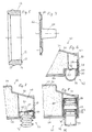
- the print head 1 is only indicated schematically. It consists of a rectangular base plate 2, from which a projection 3 protrudes along a narrow side. A nozzle plate 5 is installed in the end face 4 of this projection 3.
- the nozzle plate 5 contains a series of narrow ink channels. The pressure in these channels can be increased piezoelectrically or thermoelectrically, so that an ink droplet is ejected from the nozzle in question. The surface tension at the nozzle mouth then sucks the ejected ink volume out of an interior space 6 of a tubular nozzle 7 communicating with the nozzle channels.
- the flat end face 8 of the nozzle 7 is covered with a close-meshed sieve 9 and projects beyond the rear side 10 of the base plate 2.
- a prismatic tube with four side walls 11 protrudes from the base plate 2, into which an ink cartridge 20 is inserted.
- a sealing ring 12, shown in more detail in FIG. 5, is placed on the section of the connecting piece 7 projecting beyond the rear.
- the elastomeric sealing ring 12, for example made of silicone rubber, is tubular and has a flat front face 13 and a circumferential sealing bead 15 on the cylindrical outer circumference 14.
- the end face 13 supports the protruding edge of the screen 9 and protects it from tearing when the cartridge 20 is pulled out
- the sealing bead 15 seals the nozzle 7 against the cartridge housing. In operation, the end face 4 is directed downward and the interior 6 is full of ink.
- two opposite side walls 11 of the printhead 1 have coaxial bores 16.
- the ink cartridge 20 has a plastic housing 22 consisting of a hollow body 24 which is open at the bottom in the illustration according to FIG. 2 and is closed off by a cover 26 which is sealed or glued on.
- An end wall 28 of the housing 22 has an opening 30 with a cylindrical wall 32 for receiving the nozzle 7.
- the sealing bead 15 seals against the wall 32.
- the housing 22 is largely filled with an ink-soaked foam body 34.
- Two side walls 36 of the housing 22 have spherical cap-shaped projections 38 for snapping into the holes in the side walls 11 of the print head 1.
- a cavity 40 is formed between the foam body 34 and the housing 22, which can be filled with air or ink.
- a pumping element 42 projects into this cavity 40, in the embodiment according to FIG. 2 in the form of a piston pump.
- a cylindrical tube 44, in which a piston 46 is guided, is formed on the cover 26. The piston 46 is loaded by a spring 48 into the basic position shown in FIG. 2, in which a piston shaft 50 projects beyond the housing 22.
- the piston 46 is shown enlarged in FIG. 3. It consists of a piston crown 52 and the stem 50 snapped onto it. An O-ring 54 is inserted between two end faces of the stem 50 and the bottom 52 and seals against the cylindrical inner wall of the tube 44. The interior of the shaft 50 is connected to the atmosphere via openings 56.
- the piston crown 52 contains a check valve 58.
- a pin 64 molded onto a rotationally symmetrical membrane 62 is inserted into a central bore 60.
- the membrane 62 consists of an elastomer, for example of silicone rubber. On the periphery, it has a projecting, thin-walled, thoracic segment-shaped sealing bead 66 which seals against a flat end face 68 of the piston crown 52.
- the check valve 58 has a very low opening or closing pressure of a few m bar, for example at most 20 m bar.
- An opening 70 connects the outside of the membrane 62 to the interior of the shaft 50.
- the shaft 50 of the pumping goose 42 is pressed in until ink emerges from the nozzle plate 5.
- the print head 1 is expediently held with the nozzle plate 5 upward so that the air can escape from the space 6.
- the interior 6 is then filled with ink and the print head 1 is ready for operation.
- the shaft 50 is released, there is then a negative pressure of a few m bar inside the housing 22, so that no more ink can drip from the nozzle plate 5.
- the stroke volume of the piston 46 is preferably somewhat larger than the volume of the interior 6. This space 6 can be filled with a single push in of the piston 46. However, the check valve 58 also makes it possible to repeat the pumping process if a single push-in is not sufficient.
- FIGS. 6-8 differ from those according to FIGS. 2-4 only in the design of the pumping goose 42, so that the parts identical to the embodiment according to FIGS. 2-4 are partially omitted in the illustration according to FIGS. 6-8. Analog parts have the same reference numerals, so that a detailed description of these parts is unnecessary.
- the pump element 42 is designed as a bellows pump.
- the pumping element 42 according to FIG. 6 has a dome-shaped, elastomeric bellows 76 with a flange 78 which is clamped between a sleeve 80 pressed into the tube 44 and an end wall 82 of the tube 44.
- the wall 82 has an opening 84.
- the check valve 58 which can be designed, for example, in the same way as that according to FIGS. 3 and 4, is inserted here into the end wall 86 of the housing 22 opposite the end wall 28.
- the bellows 76 is a bellows which is pushed onto a tubular extension 88 of the wall 82.
- the check valve 58 is mounted here in the wall 82.
- FIG. 8 differs from that according to FIGS. 2-4 in that the spring 48 and the check valve 58 are missing.
- the piston 46 is pressed in two stages into the depressed position which is also shown. In a first stage, the piston is pushed in so that the O-ring 54 is still on the side of the radial opening 90 in the tube 44 facing the cover 26. This position can be determined by a locking stop (not shown) or by the outer end face 92 of the piston skirt 50 being flush with the outer face of the cover 26.
- the opening 90 can also be formed, for example, in the end wall 86 and can be closed in the delivery state, for example by an adhesive tape.
- the "two-phase movement" consists in pressing in the piston 46 and then detaching the adhesive tape.
- the opening 30 of the housing 22 is also sealed by an adhesive film which is removed before the ink cartridge 20 is inserted into the print head 1.
- the print head 1 has the same design as that according to FIG. 1, except that the sealing ring 12 is missing.
- the cartridge 120 of the embodiment according to FIG. 9 consists of a housing 121 with a prismatic hollow body 122 which is open on one side and has four side walls 123 and a rear wall 124 made of thermoplastic material and which is sealed on the free end edge of the hollow body 121, e.g. cover 125 welded on with ultrasound.
- Cover 125 engages with a circumferential rim 126 in a form-fitting manner in the inside of side walls 123.
- Adjacent to one narrow side, the cover 125 has a bore 127 in which the socket 7 fits.
- Adjacent to the opposite narrow side, the cover 125 has a small ventilation hole 128 which is aligned with a channel 130 formed by closely adjacent inner ribs 129 on the one side wall 123.
- the channel 130 opens out on the rear wall 124 into a ventilation cavity 132, likewise formed by ribs 131.
- An open-pore foam body 135 is inserted into the housing 121 with some compression.
- the foam is suitable e.g. "Melamine” foam (registered trademark) or polyurethane foam.
- Body 135 is soaked in ink.
- an elastomeric sealing film 136 e.g. made of silicone rubber, which has the size of the inner contour of the hollow body 122 at the free edge.
- the sealing film 136 has a circular hole 137 of smaller diameter coaxial to the bore 127. With the edge region adjacent to this hole 137, the film 136 seals the interior of the housing 121 against the end face 8 of the connector 7. In the area of the vent hole 128, the film 136 has a further recess.
- Two opposite side walls 123 of the hollow body 122 each have a spherical cap-shaped locking projection 139.
- the projections 139 snap into corresponding bores in the side walls 11 of the print head 1.
- two opposite side walls 123 of the housing 121 have molded-on grip cams 140, which make it easier for the cartridge 120 to be pulled out of the print head 1.
- the bore 127 and the ventilation hole 128 are closed with an adhesive strip or a sealing film 141 for transport and storage. This ensures clean handling of the cartridge 120.
- the film 141 closes both openings at the same time, it is avoided that the ventilation hole 128 could remain closed due to incorrect operation when inserting the cartridge 120, as a result of which a reliable operation of the print head 1 would not be possible. For this reason, the arrangement of the ventilation hole 128 in the cover 125 is advantageous.
- the channels 130, 132 formed by the ribs 129, 131 nevertheless ensure that the foam body 135 is exposed to atmospheric pressure, as desired from the opposite side of the bore 127.
- the nozzle 7 compresses the foam body 135 locally and therefore at the same time presses an ink supply into the interior 6 of the nozzle 7. This ensures reliable operation of the print head 1 immediately after the cartridge 20 is inserted. Because the relatively large-area sieve 9 of the nozzle 7 presses directly onto the foam body 135, the ink supply is guaranteed until the end of the ink supply. The contact pressure of the foam body 135 against the screen 9 of the nozzle 7 can be ensured by a positive engagement of the locking cams 139 in the locking holes of the print head 1.
Abstract
Description
In der EP-A-408 241 ist ein Druckkopf für einen Ink-Jet-Printer mit einer auswechselbaren Tintenpatrone beschrieben: Auf einer Grundplatte des Druckkopfs ist auf der einen Seite die Düsenplatte und auf der gegenüberliegenden Seite ein Halterfür die Tintenpatrone angeordnet. Die Patrone enthält einen mit Tinte getränkten Schaumkörper. Auf der der Grundplatte zugewandten Seite hat der Boden des Patronengehäuses einen Hohlraum, der gegen aussen durch einen Gummipfropfen abgeschlossen und gegen den Schaumkörper durch ein Sieb abgegrenzt ist. Von der Grundplatte steht eine Nadel ab, deren Kapillare über Hohlräume mit den Tintenkanälen der Düsenplatte kommuniziert. Mit der Nadel wird der Gummipfropfen beim Einsetzen der Patrone durchstochen. Ihre Spitze ragt dann in den Hohlraum. Der Deckel auf der gegenüberliegenden Seite des Gehäuses hat eine Belüftungsöffnung, die in einen weiteren Hohlraum mündet. Diese Lösung setzt für einen einwandfreien Betrieb voraus, dass der erstgenannte Hohlraum immer mit Tinte gefüllt bleibt, was insbesondere gegen das Ende des Tintenvorrates nicht garantiert werden kann.EP-A-408 241 describes a print head for an ink jet printer with an exchangeable ink cartridge: on a base plate of the print head, the nozzle plate is arranged on one side and a holder for the ink cartridge on the opposite side. The cartridge contains a foam body soaked in ink. On the side facing the base plate, the bottom of the cartridge housing has a cavity which is closed off from the outside by a rubber plug and is delimited from the foam body by a sieve. A needle protrudes from the base plate, the capillary of which communicates with the ink channels of the nozzle plate via cavities. The rubber plug is pierced with the needle when inserting the cartridge. Its tip then protrudes into the cavity. The cover on the opposite side of the housing has a ventilation opening that opens into another cavity. For a problem-free operation, this solution presupposes that the first-mentioned cavity always remains filled with ink, which cannot be guaranteed, in particular, towards the end of the ink supply.
Der vorliegenden Erfindung liegt die Aufgabe zugrunde, eine Tintenpatrone der eingangs genannten Art derart auszubilden, dass der Tintenvorrat besser ausgenützt werden kann.The present invention has for its object to design an ink cartridge of the type mentioned in such a way that the ink supply can be better used.
Die erfindungsgemässe Tintenpatrone für einen Druckkopf eines Ink-Jet-Printers umfasst ein allseits geschlossenes Gehäuse mit einer Stirnwand, die eine Oeffnung zur Aufnahme eines rohrförmigen Stutzens des Druckkopfs aufweist. Das Gehäuse enthält einen mit Tinte getränkten Schaumkörper. Es hat Rastelemente zum Einrasten in Rastmittel des Druckkopfs sowie eine zweite, kleinere Oeffnung für die Luftzufuhr.The ink cartridge according to the invention for a print head of an ink jet printer comprises a housing which is closed on all sides and has an end wall which has an opening for receiving a tubular nozzle of the print head. The housing contains a foam body soaked in ink. It has snap-in elements for snapping into the snap-in means of the print head and a second, smaller opening for the air supply.
Nachfolgend werden Ausführungsbeispiele der Erfindung anhand der Zeichnung erläutert. Darin zeigt:
Figur 1 einen Längsschnitt durch einen Druckkopf mit Tintenpatrone,Figur 2 einen Längsschnitt durch die Patrone nachFigur 1- Figur 3 einen vergrösserten Axialschnitt durch den Kolben,
Figur 4 einen Axialschnitt durch eine Dichtung,- Figur 5 einen Axialschnitt durch eine weitere Dichtung,
- Figuren 6-8 Varianten der Ausführungsform nach Figuren 2-4,
Figur 9 einen Längsschnitt durch einen DruckkopfmiteingesetzterTintenpatroneeinerweiterenAusführungsform,Figur 10 eine Stirnansicht der Patrone der Ausführungsform nachFigur 9,Figur 11 eine Stirnansicht eines Gehäuseteils, undFigur 12 eine Ansicht einer Dichtfolie.
- FIG. 1 shows a longitudinal section through a printhead with an ink cartridge,
- FIG. 2 shows a longitudinal section through the cartridge according to FIG. 1
- FIG. 3 shows an enlarged axial section through the piston,
- FIG. 4 shows an axial section through a seal,
- FIG. 5 shows an axial section through a further seal,
- FIGS. 6-8 variants of the embodiment according to FIGS. 2-4,
- FIG. 9 shows a longitudinal section through a printhead with an ink cartridge of another embodiment,
- FIG. 10 shows an end view of the cartridge of the embodiment according to FIG. 9,
- Figure 11 is an end view of a housing part, and
- Figure 12 is a view of a sealing film.
In Figur 1 ist der Druckkopf 1 nur schematisch angedeutet. Er besteht aus einer rechteckigen Grundplatte 2, von der längs einer Schmalseite ein Vorsprung 3 vorsteht. In der Stirnfläche 4 dieses Vorsprungs 3 ist eine Düsenplatte 5 eingebaut. Die Düsenplatte 5 enthält eine Reihe enger Tintenkanäle. Der Druck in diesen Kanälen kann impulsartig piezoelektrisch oder thermoelektrisch erhöht werden, sodass aus der betreffenden Düse ein Tintentröpfchen ausgestossen wird. Die Oberflächenspannung an der Düsenmündung saugt anschliessend das ausgestossene Tintenvolumen aus einem mit den Düsenkanälen kommunizierenden Innenraum 6 eines rohrförmigen Stutzens 7 an. Die ebene Stirnfläche 8 des Stutzens 7 ist mit einem engmaschigen Sieb 9 abgedeckt und überragt die Rückseite 10 der Grundplatte 2. Von der Grundplatte 2 steht auf der Rückseite ein prismatisches Rohr mit vier Seitenwänden 11 ab, in welches eine Tintenpatrone 20 eingesteckt ist. Auf den die Rückseite überragenden Abschnitt des Stutzens 7 ist ein in Figur 5 detaillierter dargestellter Dichtring 12 aufgesetzt. Der elastomere Dichtring 12, zum Beispiel aus Silikongummi, ist rohrförmig und hat vorn eine ebene Stirnfläche 13 und am zylindrischen Aussenumfang 14 einen umlaufenden Dichtwulst 15. Die Stirnfläche 13 stützt den überstehenden Rand des Siebes 9 und schützt ihn vor dem Abreissen beim Ausziehen der Patrone 20. Der Dichtwulst 15 dichtet den Stutzen 7 gegen das Patronengehäuse ab. Im Betrieb ist die Stirnfläche 4 nach unten gerichtet und der Innenraum 6 voll Tinte. Zum Einrasten der Patrone 20 haben zwei gegenüberliegende Seitenwände 11 des Druckkopfs 1 koaxiale Bohrungen 16.In Figure 1, the
Die Tintenpatrone 20 hat ein Kunststoffgehäuse 22 bestehend aus einem in der Darstellung nach Figur 2 unten offenen Hohlkörper 24, der durch einen aufgesiegelten oder aufgeklebten Deckel 26 abgeschlossen ist. Eine Stirnwand 28 des Gehäuses 22 hat eine Oeffnung 30 mit einer zylindrischen Wand 32 zur Aufnahme des Stutzens 7. Der Dichtwulst 15 dichtet gegen die Wand 32 ab. Das Gehäuse 22 ist grösstenteils mit einem tintengetränkten Schaumkörper 34 gefüllt. Zwei Seitenwände 36 des Gehäuses 22 haben kugelkalottenförmige Vorsprünge 38 zum Einrasten in die Bohrungen der Seitenwände 11 des Druckkopfs 1.The
An der der Stirnwand 28 gegenüberliegenden Seite ist zwischen dem Schaumkörper 34 und dem Gehäuse 22 ein Hohlraum 40 gebildet, der mit Luft oder Tinte gefüllt sein kann. In diesen Hohlraum 40 ragt ein Pumporgan 42, bei derAusführungsform nach Figur2 in Form einer Kolbenpumpe. Am Deckel 26 ist ein zylindrisches Rohr 44 angeformt, in welchem ein Kolben 46 geführt ist. Der Kolben 46 ist durch eine Feder 48 in die in Figur 2 dargestellte Grundstellung belastet, in welcher ein Kolbenschaft 50 über das Gehäuse 22 vorsteht.On the side opposite the
Der Kolben 46 ist in Figur 3 vergrössert dargestellt. Er besteht aus einem Kolbenboden 52 und dem darauf aufgeschnappten Schaft 50. Zwischen zwei Stirnflächen von Schaft 50 und Boden 52 ist ein O-Ring 54 eingesetzt, der gegen die zylindrische Innenwand des Rohres 44 abdichtet. Der Innenraum des Schaftes 50 ist über Oeffnungen 56 mit der Atmosphäre verbunden. Der Kolbenboden 52 enthält ein Rückschlagventil 58. In eine zentrische Bohrung 60 ist ein an eine rotationssymmetrische Membran 62 angeformter Zapfen 64 eingesteckt. Die Membran 62 besteht aus einem Elastomer, zum Beispiel aus Silikongummi. An der Peripherie hat sie einen vorstehenden, dünnwandigen, thorussegmentförmigen Dichtwulst 66, der gegen eine ebene Stirnfläche 68 des Kolbenbodens 52 abdichtet. Das Rückschlagventil 58 hat einen sehr geringen Oeffnungs- oder Schliessdruckdruck von einigen m bar, zum Bei-spiel höchstens 20 m bar. Eine Oeffnung 70 verbindet die Aussenseite der Membran 62 mit dem Innenraum des Schaftes 50.The
Nach dem Einsetzen der Patrone 20 in den Druckkopf 1 wird der Schaft 50 des Pumporgans 42 eingedrückt, bis Tinte aus der Düsenplatte 5 austritt. Zweckmässig wird dabei der Druckkopf 1 mit der Düsenplatte 5 nach oben gehalten, damit die Luft aus dem Raum 6 entweichen kann. Dann ist der Innenraum 6 mit Tinte gefüllt und der Druckkopf 1 betriebsbereit. Beim Loslassen des Schaftes 50 herrscht anschliessend im Innern des Gehäuses 22 ein Unterdruck von wenigen m bar, sodass aus der Düsenplatte 5 keine Tinte mehr tropfen kann. Durch die beschriebene Ausbildung der Tintenpatrone wird damit eine einfache und sichere Inbetriebnahme erreicht.After the
Das Hubvolumen des Kolbens 46 ist vorzugsweise etwas grösser als das Volumen des Innenraums 6. Dadurch kann mit einem einzigen Eindrücken des Kolbens 46 dieser Raum 6 gefüllt werden. Es ist jedoch durch das Rückschlagventil 58 auch möglich, den Pumpvorgang zu wiederholen, wenn ein einmaliges Eindrücken nicht ausreichen sollte.The stroke volume of the
Die Ausführungsformen nach Figuren 6-8 unterscheiden sich von jener nach Figuren 2-4 nur durch die Ausbildung des Pumporgans 42, sodass die mit der Ausführungsform nach Figuren 2-4 identischen Teile in der Darstellung nach Figuren 6-8 teilweise weggelassen sind. Analoge Teile tragen gleiche Bezugszeichen, sodass sich eine detaillierte Beschreibung dieser Teile erübrigt.The embodiments according to FIGS. 6-8 differ from those according to FIGS. 2-4 only in the design of the pumping
Bei der Ausführungsform nach Figuren 6 und 7 ist das Pumporgan 42 als Balgpumpe ausgebildet. Das Pumporgan 42 nach Figur 6 hat einen domförmigen, elastomeren Balg 76 mit einem Flansch 78, der zwischen einer ins Rohr 44 eingepressten Hülse 80 und einer Stirnwand 82 des Rohres 44 eingeklemmt ist. Die Wand 82 hat eine Oeffnung 84. Das Rückschlagventil 58, das zum Beispiel gleich ausgebildet sein kann wie jenes nach Figuren 3 und 4, ist hier in die der Stirnwand 28 gegenüberliegende Stirnwand 86 des Gehäuses 22 eingesetzt.In the embodiment according to FIGS. 6 and 7, the
Bei der Variante nach Figur 7 ist der Balg 76 ein Faltenbalg, der auf einen rohrförmigen Ansatz 88 der Wand 82 aufgeschoben ist. Das Rückschlagventil 58 ist hier in der Wand 82 montiert.In the variant according to FIG. 7, the
Die Ausführungsform nach Figur 8 unterscheidet sich von jener nach Figuren 2-4 dadurch, dass die Feder 48 und das Rückschlagventil 58 fehlen. Hier wird der Kolben 46 nach dem Einsetzen der Patrone 20 in den Druckkopf 1 in zwei Stufen in die ebenfalls dargestellte, eingedrückte Stellung gedrückt. In einer ersten Stufe wird der Kolben so eingeschoben, dass der O-Ring 54 noch auf der dem Deckel 26 zugewandten Seite einer radialen Oeffnung 90 im Rohr 44 ist. Diese Stellung kann durch einen nicht dargestellten Rastanschlag oder dadurch bestimmt sein, dass die äussere Stirnfläche 92 des Kolbenschaftes 50 mit der Aussenfläche des Deckels 26 bündig ist. In dieser Stellung wird abgewartet, bis Tinte aus der Düsenplatte 5 austritt und anschliessend der Kolben 46 weitergeschoben, sodass der Raum 40 nunmehr über die Oeffnung 90 mit derAussenatmosphäre kommuniziert, ein verbleibender Ueberdruck im Raum 40 abgebaut und im späteren Betrieb ein Nachfliessen von Luft zum Ersatz des verbrauchten Tintenvolumens ermöglicht ist.The embodiment according to FIG. 8 differs from that according to FIGS. 2-4 in that the
Abweichend von der Ausführungsform nach Figur 8 kann die Oeffnung 90 auch zum Beispiel in der Stirnwand 86 ausgebildet und im Lieferzustand zum Beispiel durch ein Klebband verschlossen sein. In diesem Fall besteht die "Zweiphasenbewegung" im Eindrücken des Kolbens 46 und anschliessenden Ablösen des Klebbandes.In a departure from the embodiment according to FIG. 8, the
Im Lieferzustand wird auch die Oeffnung 30 des Gehäuses 22 durch eine Klebfolie versiegelt, die vor dem Einsetzen der Tintenpatrone 20 in den Druckkopf 1 entfernt wird.In the delivery state, the
Bei der Ausführungsform nach Figur 9 ist der Druckkopf 1 gleich ausgebildet, wie jener nach Figur 1, nur dass der Dichtring 12 fehlt.In the embodiment according to FIG. 9, the
Die Patrone 120 der Ausführungsform nach Fig. 9 besteht aus einem Gehäuse 121 mit einem einseitig offenen, prismatischen Hohlkörper 122 mit vier Seitenwänden 123 und einer Rückwand 124 aus thermoplastischem Kunststoff und einem auf dem freien Stirnrand des Hohlkörpers 121 aufgesiegelten, z.B. mit Ultraschall aufgeschweissten Deckel 125. Der Deckel 125 greift mit einem umlaufenden Bord 126 formschlüssig in die Innenseite der Seitenwände 123 ein. Benachbart der einen Schmalseite hatder Deckel 125 eine Bohrung 127, in welche der Stutzen 7 passt. Benachbart der gegenüberliegenden Schmalseite hat der Deckel 125 ein kleines Belüftungsloch 128, das mit einem durch eng benachbarte, innere Rippen 129 an der einen Seitenwand 123 gebildeten Kanal 130 fluchtet. Der Kanal 130 mündet an der Rückwand 124 in einen ebenfalls durch Rippen 131 gebildeten Belüftungshohlraum 132.The
In das Gehäuse 121 ist ein offenporiger Schaumkörper 135 unter etwas Kompression eingesetzt. Als Schaumstoff eignet sich z.B. "Melamin"-Schaumstoff (eingetragenes Warenzeichen) oder Polyurethan-Schaumstoff. Der Körper 135 ist mit Tinte getränkt. Zwischen den Schaumkörper 135 und den Deckel 125 ist eine elastomere Dichtfolie 136 z.B. aus Silikongummi eingesetzt, welche die Grösse der Innenkonturdes Hohlkörpers 122 am freien Rand hat. Die Dichtfolie 136 hat koaxial zur Bohrung 127 ein kreisrundes Loch 137 kleineren Durchmessers. Mit dem Randbereich benachbart diesem Loch 137 dichtet die Folie 136 den Innenraum des Gehäuses 121 gegen die Stirnfläche 8 des Stutzens 7 ab. In der Gegend des Belüftungslochs 128 hatdie Folie 136 eine weitere Ausnehmung.An open-
Zwei gegenüberliegende Seitenwände 123 des Hohlkörpers 122 haben je einen kugelkalottenförmigen Rastvorsprung 139. Die Vorsprünge 139 rasten in entsprechende Bohrungen der Seitenwände 11 des Druckkopfs 1 ein. In der in eingesetzter Position des Druckkopfs 1 freien Partie haben zwei gegenüberliegende Seitenwände 123 des Gehäuses 121 angeformte Griffnocken 140, die ein Ausziehen der Patrone 120 aus dem Druckkopf 1 erleichtern. Die Bohrung 127 und das Belüftungsloch 128 sind für Transport und Lagerung mit einem Klebstreifen oder einer Siegelfolie 141 verschlossen. Dadurch wird eine saubere Handhabung der Patrone 120 gewährleistet. Weil die Folie 141 gleichzeitig beide Oeffnungen verschliesst, wird vermieden, dass durch Fehlbedienung beim Einsetzen der Patrone 120 das Belüftungsloch 128 verschlossen bleiben könnte, wodurch ein sicherer Betrieb des Druckkopfs 1 nicht möglich wäre. Aus diesem Grunde ist die Anordnung des Belüftungslochs 128 im Deckel 125 vorteilhaft. Die durch die Rippen 129, 131 gebildeten Kanäle 130, 132 sorgen trotzdem für die von der Gegenseite der Bohrung 127 erwünschte Beaufschlagung des Schaumkörpers 135 mit Atmosphärendruck.Two
Wenn die Patrone 120 in den Druckkopf 1 eingesetzt wird, komprimiert der Stutzen 7 den Schaumkörper 135 örtlich und presst deshalb zugleich einen Tintenvorrat in den Innenraum 6 des Stutzens 7. Dadurch wird ein zuverlässiger Betrieb des Druckkopfes 1 unmittelbar nach dem Einsetzen der Patrone 20 erreicht. Weil das relativ grossflächige Sieb 9 des Stutzens 7 unmittelbar auf den Schaumkörper 135 presst, ist der Tintennachschub bis ans Ende des Tintenvorrates gewährleistet. Der Anpressdruck des Schaumkörpers 135 gegen das Sieb 9 des Stutzens 7 kann dabei durch einen formschlüssigen Eingriff der Rastnocken 139 in den Rastbohrungen des Druckkopfs 1 sichergestellt werden.When the
Claims (17)
Applications Claiming Priority (4)
| Application Number | Priority Date | Filing Date | Title |
|---|---|---|---|
| DE9203206U DE9203206U1 (en) | 1992-03-10 | 1992-03-10 | |
| DE9203206U | 1992-03-10 | ||
| DE9300132U DE9300132U1 (en) | 1993-01-07 | 1993-01-07 | |
| DE9300132U | 1993-01-07 |
Publications (3)
| Publication Number | Publication Date |
|---|---|
| EP0560729A2 true EP0560729A2 (en) | 1993-09-15 |
| EP0560729A3 EP0560729A3 (en) | 1994-06-22 |
| EP0560729B1 EP0560729B1 (en) | 1996-05-15 |
Family
ID=25959256
Family Applications (1)
| Application Number | Title | Priority Date | Filing Date |
|---|---|---|---|
| EP93810169A Expired - Lifetime EP0560729B1 (en) | 1992-03-10 | 1993-03-05 | Ink cartridge for a printhead of an ink jet printer |
Country Status (4)
| Country | Link |
|---|---|
| EP (1) | EP0560729B1 (en) |
| AT (1) | ATE138015T1 (en) |
| DE (1) | DE59302549D1 (en) |
| ES (1) | ES2087698T3 (en) |
Cited By (24)
| Publication number | Priority date | Publication date | Assignee | Title |
|---|---|---|---|---|
| EP0672527A2 (en) * | 1994-03-16 | 1995-09-20 | Pelikan Produktions Ag | Multi-colour print head for an ink jet printer |
| EP0676294A2 (en) * | 1994-04-06 | 1995-10-11 | Pelikan Produktions Ag | Ink jet print cartridge |
| DE19512812A1 (en) * | 1994-11-29 | 1996-05-30 | Hewlett Packard Co | Refilling method and refilling device for ink cartridge units |
| GB2298616A (en) * | 1992-07-31 | 1996-09-11 | Canon Kk | Liquid storing container for a recording apparatus |
| EP0741038A2 (en) * | 1995-04-27 | 1996-11-06 | Owens-Illinois Closure Inc. | Liquid containment and dispensing device |
| US5619237A (en) * | 1994-08-24 | 1997-04-08 | Canon Kabushiki Kaisha | Replaceable ink tank |
| US5619239A (en) * | 1993-11-29 | 1997-04-08 | Canon Kabushiki Kaisha | Replaceable ink tank |
| US5631682A (en) * | 1993-07-06 | 1997-05-20 | Brother Kogyo Kabushiki Kaisha | Printhead ink supply device |
| EP0778143A1 (en) * | 1995-12-04 | 1997-06-11 | Hewlett-Packard Company | Ink cartridge adapters |
| EP0778146A1 (en) * | 1995-12-04 | 1997-06-11 | Hewlett-Packard Company | Ink supply for an ink-jet printer |
| EP0780234A2 (en) | 1995-12-21 | 1997-06-25 | Pelikan Produktions Ag | Ink cartridge and printhead for an inkjet printer |
| DE19548032A1 (en) * | 1995-12-21 | 1997-07-03 | Pelikan Produktions Ag | Liquid, esp. ink cartridge for print head of ink jet printer |
| US5663753A (en) * | 1994-11-14 | 1997-09-02 | Jetfill, Inc. | Recording cartridge with replaceable liquid-containing reservoir |
| US5801737A (en) * | 1994-05-25 | 1998-09-01 | Canon Kabushiki Kaisha | Ink container with internal air pressure adjustment |
| US5805189A (en) * | 1994-12-06 | 1998-09-08 | Eastman Kodak Company | Device for fluid supply of a micro-metering device |
| US5917525A (en) * | 1995-10-30 | 1999-06-29 | Pelikan Produktions Ag | Ink cartridge for a print head of an ink-jet printer |
| US5949461A (en) * | 1994-02-18 | 1999-09-07 | Nu-Kote Imaging International, Inc. | Ink refill bottle |
| EP0968829A2 (en) * | 1998-06-29 | 2000-01-05 | Hewlett-Packard Company | Method and apparatus for removing air from an inkjet print cartridge |
| US6170939B1 (en) | 1992-07-31 | 2001-01-09 | Canon Kabushiki Kaisha | Liquid storing container for recording apparatus |
| EP1134083A2 (en) | 1995-12-21 | 2001-09-19 | Pelikan Hardcopy Production AG | Liquid cartridge and print head for an ink jet printer |
| EP1186420A1 (en) * | 1999-05-06 | 2002-03-13 | Firma Artech GmbH, design + production in plastic | Ink supply container for an ink jet print head |
| EP1279509A1 (en) | 2001-07-24 | 2003-01-29 | Pelikan Harcopy Production AG | Device for cleaning a printhead of an inkjet printer |
| DE19614364B4 (en) * | 1995-05-10 | 2007-08-23 | Pelikan Produktions Ag | Printhead for an inkjet printer |
| DE19618986B4 (en) * | 1995-10-30 | 2012-09-27 | Pelikan Produktions Ag | Ink cartridge for a print head of an inkjet printer |
Citations (1)
| Publication number | Priority date | Publication date | Assignee | Title |
|---|---|---|---|---|
| EP0378240A2 (en) | 1989-01-13 | 1990-07-18 | Canon Kabushiki Kaisha | Ink storage portion |
Family Cites Families (2)
| Publication number | Priority date | Publication date | Assignee | Title |
|---|---|---|---|---|
| JPS59131837U (en) * | 1983-02-23 | 1984-09-04 | シャープ株式会社 | Ink cartridge device for inkjet printers |
| US4785314A (en) * | 1984-03-14 | 1988-11-15 | Canon Kabushiki Kaisha | Internally pressure-regulated ink supply |
-
1993
- 1993-03-05 EP EP93810169A patent/EP0560729B1/en not_active Expired - Lifetime
- 1993-03-05 ES ES93810169T patent/ES2087698T3/en not_active Expired - Lifetime
- 1993-03-05 DE DE59302549T patent/DE59302549D1/en not_active Expired - Lifetime
- 1993-03-05 AT AT93810169T patent/ATE138015T1/en not_active IP Right Cessation
Patent Citations (1)
| Publication number | Priority date | Publication date | Assignee | Title |
|---|---|---|---|---|
| EP0378240A2 (en) | 1989-01-13 | 1990-07-18 | Canon Kabushiki Kaisha | Ink storage portion |
Non-Patent Citations (1)
| Title |
|---|
| IBM TECHNICAL DISCLOSURE BULLETIN, vol. 34, no. 1, June 1991 (1991-06-01), pages 459 |
Cited By (55)
| Publication number | Priority date | Publication date | Assignee | Title |
|---|---|---|---|---|
| US5781213A (en) * | 1992-07-31 | 1998-07-14 | Canon Kabushiki Kaisha | Liquid storing container having filter interface for recording apparatus |
| GB2298616B (en) * | 1992-07-31 | 1997-03-19 | Canon Kk | Liquid storing container for recording apparatus |
| US6170939B1 (en) | 1992-07-31 | 2001-01-09 | Canon Kabushiki Kaisha | Liquid storing container for recording apparatus |
| GB2298616A (en) * | 1992-07-31 | 1996-09-11 | Canon Kk | Liquid storing container for a recording apparatus |
| US5583549A (en) * | 1992-07-31 | 1996-12-10 | Canon Kabushiki Kaisha | Liquid storing container for recording apparatus |
| US5589862A (en) * | 1992-07-31 | 1996-12-31 | Canon Kabushiki Kaisha | Liquid storing container for recording apparatus |
| GB2269784B (en) * | 1992-07-31 | 1997-03-19 | Canon Kk | Liquid storing container for recording apparatus |
| US5631682A (en) * | 1993-07-06 | 1997-05-20 | Brother Kogyo Kabushiki Kaisha | Printhead ink supply device |
| US6145975A (en) * | 1993-11-29 | 2000-11-14 | Canon Kabushiki Kaisha | Method of mounting an exchangeable ink container |
| US5619239A (en) * | 1993-11-29 | 1997-04-08 | Canon Kabushiki Kaisha | Replaceable ink tank |
| US6243116B1 (en) | 1993-11-29 | 2001-06-05 | Canon Kabushiki Kaisha | Ink container, installing-removing method therefore and apparatus usable with the same |
| US6070974A (en) * | 1993-11-29 | 2000-06-06 | Canon Kabushiki Kaisha | Ink jet unit for a detachably mountable ink container |
| US5949461A (en) * | 1994-02-18 | 1999-09-07 | Nu-Kote Imaging International, Inc. | Ink refill bottle |
| US5724081A (en) * | 1994-03-16 | 1998-03-03 | Pelikan Produktions Ag | Multi-color print head for an ink-jet printer |
| EP0672527A3 (en) * | 1994-03-16 | 1997-04-16 | Pelikan Produktions Ag | Multi-colour print head for an ink jet printer. |
| EP0672527A2 (en) * | 1994-03-16 | 1995-09-20 | Pelikan Produktions Ag | Multi-colour print head for an ink jet printer |
| EP0676294A2 (en) * | 1994-04-06 | 1995-10-11 | Pelikan Produktions Ag | Ink jet print cartridge |
| EP0676294A3 (en) * | 1994-04-06 | 1998-01-07 | Pelikan Produktions Ag | Ink jet print cartridge |
| US5801737A (en) * | 1994-05-25 | 1998-09-01 | Canon Kabushiki Kaisha | Ink container with internal air pressure adjustment |
| US7914137B2 (en) | 1994-08-24 | 2011-03-29 | Canon Kabushiki Kaisha | Ink container for ink jet printer, holder for the container, carriage for the holder, and ink jet printer |
| US5619237A (en) * | 1994-08-24 | 1997-04-08 | Canon Kabushiki Kaisha | Replaceable ink tank |
| US6361158B1 (en) | 1994-08-24 | 2002-03-26 | Canon Kabushiki Kaisha | Ink container for ink jet printing, holder for the container, carriage for the holder and ink jet printer |
| US7401909B2 (en) | 1994-08-24 | 2008-07-22 | Canon Kabushiki Kaisha | Ink container for ink jet printer, holder for the container, carriage for the holder and ink jet printer |
| US7407275B2 (en) | 1994-08-24 | 2008-08-05 | Canon Kabushiki Kaisha | Ink container for ink jet printer, holder for the container, carriage for the holder and ink jet printer |
| US6336709B1 (en) | 1994-08-24 | 2002-01-08 | Canon Kabushiki Kaisha | Ink container for ink jet printer, holder for the container carriage for the holder and ink jet printer |
| US7407274B2 (en) | 1994-08-24 | 2008-08-05 | Canon Kabushiki Kaisha | Ink container for ink jet printer, holder for the container carriage for the holder and ink jet printer |
| US8425022B2 (en) | 1994-08-24 | 2013-04-23 | Canon Kabushiki Kaisha | Ink container for ink jet printer, holder for the container, carriage for the holder, and ink jet printer |
| US5663753A (en) * | 1994-11-14 | 1997-09-02 | Jetfill, Inc. | Recording cartridge with replaceable liquid-containing reservoir |
| DE19512812C2 (en) * | 1994-11-29 | 2003-11-27 | Hewlett Packard Co | Refill unit for insertion into an empty ink cartridge unit |
| DE19512812A1 (en) * | 1994-11-29 | 1996-05-30 | Hewlett Packard Co | Refilling method and refilling device for ink cartridge units |
| US5805189A (en) * | 1994-12-06 | 1998-09-08 | Eastman Kodak Company | Device for fluid supply of a micro-metering device |
| US5900896A (en) * | 1995-04-27 | 1999-05-04 | Hewlett-Packard Company | Ink cartridge adapters |
| US5784087A (en) * | 1995-04-27 | 1998-07-21 | Owens-Illinois Closure Inc. | Liquid containment and dispensing device |
| EP0741038A2 (en) * | 1995-04-27 | 1996-11-06 | Owens-Illinois Closure Inc. | Liquid containment and dispensing device |
| US6612690B1 (en) | 1995-04-27 | 2003-09-02 | Owens-Illinois Closure Inc. | Liquid containment and dispensing device |
| EP0741038A3 (en) * | 1995-04-27 | 1998-01-21 | Owens-Illinois Closure Inc. | Liquid containment and dispensing device |
| US5856839A (en) * | 1995-04-27 | 1999-01-05 | Hewlett-Packard Company | Ink supply having an integral pump |
| EP1190861A1 (en) * | 1995-04-27 | 2002-03-27 | Owens-Illinois Closure Inc. | Liquid containment and dispensing device |
| DE19614364B4 (en) * | 1995-05-10 | 2007-08-23 | Pelikan Produktions Ag | Printhead for an inkjet printer |
| DE19614364B8 (en) * | 1995-05-10 | 2007-11-22 | Pelikan Produktions Ag | Printhead for an inkjet printer |
| US5917525A (en) * | 1995-10-30 | 1999-06-29 | Pelikan Produktions Ag | Ink cartridge for a print head of an ink-jet printer |
| DE19618986B4 (en) * | 1995-10-30 | 2012-09-27 | Pelikan Produktions Ag | Ink cartridge for a print head of an inkjet printer |
| DE19618986B8 (en) * | 1995-10-30 | 2012-12-20 | Pelikan Produktions Ag | Ink cartridge for a print head of an inkjet printer |
| EP0778146A1 (en) * | 1995-12-04 | 1997-06-11 | Hewlett-Packard Company | Ink supply for an ink-jet printer |
| EP0778143A1 (en) * | 1995-12-04 | 1997-06-11 | Hewlett-Packard Company | Ink cartridge adapters |
| EP1134083A2 (en) | 1995-12-21 | 2001-09-19 | Pelikan Hardcopy Production AG | Liquid cartridge and print head for an ink jet printer |
| DE19548032A1 (en) * | 1995-12-21 | 1997-07-03 | Pelikan Produktions Ag | Liquid, esp. ink cartridge for print head of ink jet printer |
| EP0780234A2 (en) | 1995-12-21 | 1997-06-25 | Pelikan Produktions Ag | Ink cartridge and printhead for an inkjet printer |
| EP0780234A3 (en) * | 1995-12-21 | 1998-10-14 | Pelikan Produktions Ag | Ink cartridge and printhead for an inkjet printer |
| DE19549438C2 (en) * | 1995-12-21 | 2000-11-02 | Pelikan Produktions Ag Egg | Liquid cartridge and printhead for an ink jet printer |
| EP0968829A3 (en) * | 1998-06-29 | 2001-01-03 | Hewlett-Packard Company | Method and apparatus for removing air from an inkjet print cartridge |
| EP0968829A2 (en) * | 1998-06-29 | 2000-01-05 | Hewlett-Packard Company | Method and apparatus for removing air from an inkjet print cartridge |
| US6386693B1 (en) | 1999-05-06 | 2002-05-14 | Artech Gmbh Design And Production In Plastic | Ink supply tank for an inkjet print head |
| EP1186420A1 (en) * | 1999-05-06 | 2002-03-13 | Firma Artech GmbH, design + production in plastic | Ink supply container for an ink jet print head |
| EP1279509A1 (en) | 2001-07-24 | 2003-01-29 | Pelikan Harcopy Production AG | Device for cleaning a printhead of an inkjet printer |
Also Published As
| Publication number | Publication date |
|---|---|
| EP0560729A3 (en) | 1994-06-22 |
| ATE138015T1 (en) | 1996-06-15 |
| ES2087698T3 (en) | 1996-07-16 |
| EP0560729B1 (en) | 1996-05-15 |
| DE59302549D1 (en) | 1996-06-20 |
Similar Documents
| Publication | Publication Date | Title |
|---|---|---|
| EP0560729B1 (en) | Ink cartridge for a printhead of an ink jet printer | |
| EP0088236B1 (en) | Dispenser for liquids or viscous products | |
| DE2640575C3 (en) | Diaphragm pump | |
| DE602004001374T3 (en) | Ink cartridge and inkjet printer | |
| DE19545775C2 (en) | Liquid cartridge, in particular an ink cartridge for a print head of an ink jet printer | |
| DE3725673C2 (en) | ||
| DE4005528C2 (en) | Discharge device for media | |
| DE2538971A1 (en) | SPRAY DEVICE | |
| EP2102012B1 (en) | Ink cartridge for inkjet printers | |
| DE2633320A1 (en) | PUMP FOR DISPENSING A PRODUCT | |
| DE2732564A1 (en) | VENTILATED DISPENSING DEVICE FOR CONTINUOUS DISTRIBUTION OF A PRODUCT | |
| DE202009007139U1 (en) | Hebelsprühpumpe | |
| DE2649915B2 (en) | Hand lever spray device | |
| CH632190A5 (en) | REPLACABLE LIQUID STORAGE CARTRIDGE OF A LIQUID JET PRINTER. | |
| CH692493A5 (en) | Color cartridge. | |
| EP0676294A2 (en) | Ink jet print cartridge | |
| EP0672527B1 (en) | Multi-colour print head for an ink jet printer | |
| DE2720092A1 (en) | VALVE ARRANGEMENT | |
| EP0765769A2 (en) | Writing instrument, especially a fountain pen | |
| DE10220469A1 (en) | Container arrangement for removing and applying partial quantities of a liquid product comprises an elastic inner container for the product, an elastic outer container, and an air intake valve provided between the inner and outer containers | |
| WO2012084354A2 (en) | Discharging device for a liquid | |
| EP1533125B1 (en) | Ink cartridge, ink cartridge unit and ink jet printhead | |
| DE10324059B4 (en) | ink cartridge | |
| DE2705071C2 (en) | ||
| EP0991526B1 (en) | Device for placing a liquid on a substrate |
Legal Events
| Date | Code | Title | Description |
|---|---|---|---|
| PUAI | Public reference made under article 153(3) epc to a published international application that has entered the european phase |
Free format text: ORIGINAL CODE: 0009012 |
|
| AK | Designated contracting states |
Kind code of ref document: A2 Designated state(s): AT CH DE ES FR GB IT LI NL |
|
| PUAL | Search report despatched |
Free format text: ORIGINAL CODE: 0009013 |
|
| AK | Designated contracting states |
Kind code of ref document: A3 Designated state(s): AT CH DE ES FR GB IT LI NL |
|
| RAP1 | Party data changed (applicant data changed or rights of an application transferred) |
Owner name: PELIKAN PRODUKTIONS AG |
|
| 17P | Request for examination filed |
Effective date: 19941206 |
|
| 17Q | First examination report despatched |
Effective date: 19950425 |
|
| GRAG | Despatch of communication of intention to grant |
Free format text: ORIGINAL CODE: EPIDOS AGRA |
|
| GRAH | Despatch of communication of intention to grant a patent |
Free format text: ORIGINAL CODE: EPIDOS IGRA |
|
| GRAA | (expected) grant |
Free format text: ORIGINAL CODE: 0009210 |
|
| AK | Designated contracting states |
Kind code of ref document: B1 Designated state(s): AT CH DE ES FR GB IT LI NL |
|
| REF | Corresponds to: |
Ref document number: 138015 Country of ref document: AT Date of ref document: 19960615 Kind code of ref document: T |
|
| REG | Reference to a national code |
Ref country code: CH Ref legal event code: NV Representative=s name: ISLER & PEDRAZZINI AG PATENTANWAELTE |
|
| REG | Reference to a national code |
Ref country code: ES Ref legal event code: BA2A Ref document number: 2087698 Country of ref document: ES Kind code of ref document: T3 |
|
| REF | Corresponds to: |
Ref document number: 59302549 Country of ref document: DE Date of ref document: 19960620 |
|
| GBT | Gb: translation of ep patent filed (gb section 77(6)(a)/1977) |
Effective date: 19960610 |
|
| REG | Reference to a national code |
Ref country code: ES Ref legal event code: FG2A Ref document number: 2087698 Country of ref document: ES Kind code of ref document: T3 |
|
| ITF | It: translation for a ep patent filed |
Owner name: STUDIO TORTA SOCIETA' SEMPLICE |
|
| ET | Fr: translation filed | ||
| PLBE | No opposition filed within time limit |
Free format text: ORIGINAL CODE: 0009261 |
|
| STAA | Information on the status of an ep patent application or granted ep patent |
Free format text: STATUS: NO OPPOSITION FILED WITHIN TIME LIMIT |
|
| 26N | No opposition filed | ||
| REG | Reference to a national code |
Ref country code: GB Ref legal event code: IF02 |
|
| PGFP | Annual fee paid to national office [announced via postgrant information from national office to epo] |
Ref country code: NL Payment date: 20040317 Year of fee payment: 12 |
|
| PGFP | Annual fee paid to national office [announced via postgrant information from national office to epo] |
Ref country code: AT Payment date: 20040322 Year of fee payment: 12 |
|
| PGFP | Annual fee paid to national office [announced via postgrant information from national office to epo] |
Ref country code: ES Payment date: 20040324 Year of fee payment: 12 |
|
| PG25 | Lapsed in a contracting state [announced via postgrant information from national office to epo] |
Ref country code: AT Free format text: LAPSE BECAUSE OF NON-PAYMENT OF DUE FEES Effective date: 20050305 |
|
| PG25 | Lapsed in a contracting state [announced via postgrant information from national office to epo] |
Ref country code: ES Free format text: LAPSE BECAUSE OF NON-PAYMENT OF DUE FEES Effective date: 20050307 |
|
| PG25 | Lapsed in a contracting state [announced via postgrant information from national office to epo] |
Ref country code: NL Free format text: LAPSE BECAUSE OF NON-PAYMENT OF DUE FEES Effective date: 20051001 |
|
| NLV4 | Nl: lapsed or anulled due to non-payment of the annual fee |
Effective date: 20051001 |
|
| REG | Reference to a national code |
Ref country code: ES Ref legal event code: FD2A Effective date: 20050307 |
|
| PGFP | Annual fee paid to national office [announced via postgrant information from national office to epo] |
Ref country code: GB Payment date: 20070322 Year of fee payment: 15 |
|
| PGFP | Annual fee paid to national office [announced via postgrant information from national office to epo] |
Ref country code: CH Payment date: 20070329 Year of fee payment: 15 |
|
| REG | Reference to a national code |
Ref country code: CH Ref legal event code: PCAR Free format text: ISLER & PEDRAZZINI AG;POSTFACH 1772;8027 ZUERICH (CH) |
|
| PGFP | Annual fee paid to national office [announced via postgrant information from national office to epo] |
Ref country code: IT Payment date: 20070626 Year of fee payment: 15 |
|
| PGFP | Annual fee paid to national office [announced via postgrant information from national office to epo] |
Ref country code: FR Payment date: 20070321 Year of fee payment: 15 |
|
| REG | Reference to a national code |
Ref country code: CH Ref legal event code: PL |
|
| GBPC | Gb: european patent ceased through non-payment of renewal fee |
Effective date: 20080305 |
|
| REG | Reference to a national code |
Ref country code: FR Ref legal event code: ST Effective date: 20081125 |
|
| PG25 | Lapsed in a contracting state [announced via postgrant information from national office to epo] |
Ref country code: LI Free format text: LAPSE BECAUSE OF NON-PAYMENT OF DUE FEES Effective date: 20080331 Ref country code: CH Free format text: LAPSE BECAUSE OF NON-PAYMENT OF DUE FEES Effective date: 20080331 |
|
| PG25 | Lapsed in a contracting state [announced via postgrant information from national office to epo] |
Ref country code: FR Free format text: LAPSE BECAUSE OF NON-PAYMENT OF DUE FEES Effective date: 20080331 |
|
| PG25 | Lapsed in a contracting state [announced via postgrant information from national office to epo] |
Ref country code: GB Free format text: LAPSE BECAUSE OF NON-PAYMENT OF DUE FEES Effective date: 20080305 |
|
| PG25 | Lapsed in a contracting state [announced via postgrant information from national office to epo] |
Ref country code: IT Free format text: LAPSE BECAUSE OF NON-PAYMENT OF DUE FEES Effective date: 20080305 |
|
| PGFP | Annual fee paid to national office [announced via postgrant information from national office to epo] |
Ref country code: DE Payment date: 20120522 Year of fee payment: 20 |
|
| REG | Reference to a national code |
Ref country code: DE Ref legal event code: R084 Ref document number: 59302549 Country of ref document: DE Effective date: 20120703 |
|
| REG | Reference to a national code |
Ref country code: DE Ref legal event code: R071 Ref document number: 59302549 Country of ref document: DE |
|
| PG25 | Lapsed in a contracting state [announced via postgrant information from national office to epo] |
Ref country code: DE Free format text: LAPSE BECAUSE OF EXPIRATION OF PROTECTION Effective date: 20130306 |