EP0561666A1 - Liquid dispenser with a delivery pump and delivery pump for this dispenser - Google Patents
Liquid dispenser with a delivery pump and delivery pump for this dispenser Download PDFInfo
- Publication number
- EP0561666A1 EP0561666A1 EP93400572A EP93400572A EP0561666A1 EP 0561666 A1 EP0561666 A1 EP 0561666A1 EP 93400572 A EP93400572 A EP 93400572A EP 93400572 A EP93400572 A EP 93400572A EP 0561666 A1 EP0561666 A1 EP 0561666A1
- Authority
- EP
- European Patent Office
- Prior art keywords
- valve
- liquid
- peripheral
- chamber
- central
- Prior art date
- Legal status (The legal status is an assumption and is not a legal conclusion. Google has not performed a legal analysis and makes no representation as to the accuracy of the status listed.)
- Granted
Links
Images


Classifications
-
- B—PERFORMING OPERATIONS; TRANSPORTING
- B05—SPRAYING OR ATOMISING IN GENERAL; APPLYING FLUENT MATERIALS TO SURFACES, IN GENERAL
- B05B—SPRAYING APPARATUS; ATOMISING APPARATUS; NOZZLES
- B05B7/00—Spraying apparatus for discharge of liquids or other fluent materials from two or more sources, e.g. of liquid and air, of powder and gas
- B05B7/02—Spray pistols; Apparatus for discharge
- B05B7/06—Spray pistols; Apparatus for discharge with at least one outlet orifice surrounding another approximately in the same plane
- B05B7/062—Spray pistols; Apparatus for discharge with at least one outlet orifice surrounding another approximately in the same plane with only one liquid outlet and at least one gas outlet
- B05B7/066—Spray pistols; Apparatus for discharge with at least one outlet orifice surrounding another approximately in the same plane with only one liquid outlet and at least one gas outlet with an inner liquid outlet surrounded by at least one annular gas outlet
-
- B—PERFORMING OPERATIONS; TRANSPORTING
- B05—SPRAYING OR ATOMISING IN GENERAL; APPLYING FLUENT MATERIALS TO SURFACES, IN GENERAL
- B05B—SPRAYING APPARATUS; ATOMISING APPARATUS; NOZZLES
- B05B11/00—Single-unit hand-held apparatus in which flow of contents is produced by the muscular force of the operator at the moment of use
- B05B11/0005—Components or details
- B05B11/0037—Containers
- B05B11/0039—Containers associated with means for compensating the pressure difference between the ambient pressure and the pressure inside the container, e.g. pressure relief means
- B05B11/0041—Containers associated with means for compensating the pressure difference between the ambient pressure and the pressure inside the container, e.g. pressure relief means compensating underpressure without contact of the fluid remaining in the container with the atmospheric air
-
- B—PERFORMING OPERATIONS; TRANSPORTING
- B05—SPRAYING OR ATOMISING IN GENERAL; APPLYING FLUENT MATERIALS TO SURFACES, IN GENERAL
- B05B—SPRAYING APPARATUS; ATOMISING APPARATUS; NOZZLES
- B05B7/00—Spraying apparatus for discharge of liquids or other fluent materials from two or more sources, e.g. of liquid and air, of powder and gas
- B05B7/02—Spray pistols; Apparatus for discharge
- B05B7/10—Spray pistols; Apparatus for discharge producing a swirling discharge
-
- B—PERFORMING OPERATIONS; TRANSPORTING
- B65—CONVEYING; PACKING; STORING; HANDLING THIN OR FILAMENTARY MATERIAL
- B65D—CONTAINERS FOR STORAGE OR TRANSPORT OF ARTICLES OR MATERIALS, e.g. BAGS, BARRELS, BOTTLES, BOXES, CANS, CARTONS, CRATES, DRUMS, JARS, TANKS, HOPPERS, FORWARDING CONTAINERS; ACCESSORIES, CLOSURES, OR FITTINGS THEREFOR; PACKAGING ELEMENTS; PACKAGES
- B65D83/00—Containers or packages with special means for dispensing contents
- B65D83/14—Containers or packages with special means for dispensing contents for delivery of liquid or semi-liquid contents by internal gaseous pressure, i.e. aerosol containers comprising propellant for a product delivered by a propellant
- B65D83/16—Containers or packages with special means for dispensing contents for delivery of liquid or semi-liquid contents by internal gaseous pressure, i.e. aerosol containers comprising propellant for a product delivered by a propellant characterised by the actuating means
- B65D83/20—Containers or packages with special means for dispensing contents for delivery of liquid or semi-liquid contents by internal gaseous pressure, i.e. aerosol containers comprising propellant for a product delivered by a propellant characterised by the actuating means operated by manual action, e.g. button-type actuator or actuator caps
Definitions
- the present invention relates to a liquid dispenser equipped with a dispensing pump.
- the distribution of a liquid to be dispensed contained in a container, in the form of a spray, is, as is known, advantageously carried out by the action of a pressure.
- This can be obtained thanks to the presence, in the container, of a propellant under pressure: the disadvantage of this solution comes from the need to put the container under very high pressure from the start, in order to be able to have, in end of use of the dispenser, still sufficient pressure.
- the gas is introduced in liquefied form into the distributor: for these applications, the gas chosen is either of the chlorofluorocarbon type, and we know the harmful action caused by this type of gas on the ozone layer. , either propane and / or butane, which can cause a problem of flammability.
- the dispensing pressure can also be obtained by manual actuation of the piston of a dispensing pump fitted to the dispenser; unfortunately, this solution, if it makes it possible to avoid the drawbacks described above, does not result in a spraying as fine as that obtained by the propellant gas solutions, in particular the liquefied gas solution, in which each droplet distributed is a mixture of liquid to be dispensed and liquefied gas which, at the outlet of the dispensing nozzle, bursts the drop and makes it possible to obtain a microdiffusion of the dispensed fluid.
- the present invention relates to a distributor equipped with a pump for distributing a liquid to be sprayed, making it possible to obtain a spray fineness much greater than that obtained with distributors hitherto conventionally equipped with a distribution pump.
- the liquid distributor equipped with a distribution pump, comprises a container containing the liquid to be distributed, said distribution pump being provided with a push button whose actuation introduces liquid to be distributed into a chamber. compression, in communication with the volume of the liquid to distribute, then compresses the liquid in said chamber, then distributes the liquid under pressure through a distribution nozzle carried by the push button, which distribution nozzle comprises a central supply chamber disposed around an axis and a channel central outlet in communication on the one hand, with said central chamber and on the other hand, with the outside, characterized in that the container contains, in addition to the liquid to be dispensed, gas under pressure, the dispensing nozzle comprising a peripheral supply chamber and a peripheral outlet channel in communication, on the one hand, with said peripheral chamber and, on the other hand, with the outside, said peripheral chamber surrounding said central chamber, and the peripheral channel surrounding said central channel, the two said central and peripheral chambers as well as said peripheral channel being arranged circumferentially around said axis of said ch central am
- the pressurized gas strikes, at the outlet of the nozzle, the liquid dispensed by the actuation of the pump, and perfect the spraying, in particular the fineness of the latter.
- the dispenser carries a cup closing the container containing the liquid to be dispensed, said cup carrying, on the one hand, the pump equipped with the push button and on the other hand a valve support crossed with sealing by a control rod carried by the push button, and pierced with a channel in communication with an inlet, in the push button, of pressurized gas supply to the peripheral chamber.
- the valve support has a generally cylindrical shape, the interior of the cylinder communicating, on the one hand, with the volume of gas under pressure in the tank, on the other hand, with the channel, a ball in the support valve being urged by the pressurized gas to a seat provided in the support, and by the rod away from this seat when the push button is operated.
- the rod is mounted in a cylindrical bore in the manner of a drawer, the channel drilled in the control rod opening laterally to the external surface of the rod by means of a return, said return being either obstructed, at rest, either in communication with the gas under pressure by means of a groove in the internal wall of the valve support, position for which the communication from the interior of the valve support with the volume of gas contained in the container is closed.
- the dispensing pump is conventional, perfectly sealed at rest as in operation, the dispenser being arranged so that, when desired, the pressurized gas contained in the dispenser is brought to the peripheral chamber of the dispensing valve.
- the present invention also relates to a dispensing pump comprising the means for supplying liquid to be dispensed and pressurized gas to the central and peripheral chambers of the dispensing valve.
- the dispensing pump is characterized in that the push-button of the pump is slidably mounted on a cuff surrounding a cylindrical pump body of which it is integral, the cuff being held on the container of the reservoir by its cup via a sealing washer, the cuff being traversed in its center by a hollow piston rod, integral with the push button, and the interior of which communicates with the central chamber for its supply of liquid to be dispensed, the piston carrying a cylindrical sock surrounding the piston rod, the lip-shaped end of which cooperates with the external surface of a skirt carried by the cuff, said skirt extending outside the rod of piston and inside the sock of the piston, a first valve comprising a bearing intended to be applied on a seat under the action of a spring to close the supply of the central chamber, and a second valve comprising a bearing intended to be applied on a seat when the push button is operated to close the communication between the liquid to be dispensed contained in the container and the interior of the pump body.
- the first valve comprises a first elongated part extending inside the piston rod and carrying the seat, and a second elongated part extending outside the piston rod and cooperating with the spring.
- the second valve being cylindrical and being guided by the second elongated part of the first valve which it surrounds, the second valve being brought to cooperate in sealing by a seat with a seat carried by an enlarged part of the first valve situated between the two said elongated parts, said seat and said seat making it possible to transmit to the second valve the force applied by the push button to the first valve when it is operated, the scope of the second valve being constituted by its tubular end which s 'engages on a sealing sleeve provided in the support, so that, when this engagement takes place, a compression chamber is defined between the pump support and its piston.
- a dispenser comprises a container, closed by a cup 44, in the usual way: therefore, the entire dispenser is not shown; the cup 44 carries in a sealed manner, thanks to a seal 63, a conventional pump 41 whose rod 42 for actuating the piston carries, to do this, a push button 10, and whose dip tube plunges into the liquid to be dispensed what is in the container; as is known, the rod 42 allows the liquid to be dispensed to pass when the pump is actuated.
- the pump 41 is, for example, the pump manufactured by the company PERFECT, marketed under the commercial designation "PZ AIRLESS".
- the cup 44 also carries, according to the invention, a valve support 46 of generally cylindrical shape, the interior of which communicates, through a passage 51, with the interior space of the container not occupied by the liquid to be dispensed.
- the valve support 46 is sealed through a control rod 45 carried by the push button 10, parallel to the axis of the pump 41; the rod 45 is pierced with a channel 20.
- the valve support contains a ball 47, trapped but able to move inside, a conical seat 48 provided at the upper part of the interior of the support 46 being adapted to the ball which, when it cooperates with it, prevents any communication from inside the container to channel 20.
- the ball 47 can be replaced by a device of the "drawer" type, as shown in the variant of FIG. 3; according to this variant, the internal bore 49 of the valve support 46, of generally cylindrical shape, corresponds to the external diameter of the control rod 45, which slides in the bore 49 in the manner of a drawer; the bore 49 communicates with the interior of the container through a passage 51 passing through the wall of the support 46 located below the cup 44; the channel 20 of the rod 45 is bent at its lower part and opens out through an orifice 52 on the external surface of the rod 45.
- the orifice 52 When the push button is in its rest position, the orifice 52 is in line with the internal surface bore 49, and is thus closed; after a sufficient stroke of the push button, therefore of the rod 45, downwards, in FIG. 3, the orifice 52 is opposite a longitudinal groove 50 provided on the inner surface of the bore 49 and extending, radially, said bore.
- the push-button 10 carries a dispensing nozzle 1 similar to that which is shown, in more detail, in FIG. 6.
- the dispensing nozzle designated as a whole by the reference 1 comprises a central cup 2 fitted on a central end piece 3 carried by the push button 10; a central chamber 4 is thus defined by the internal face 5 of the central cup 2 and the external face 6 of the central end piece 3.
- the bottom of the central cup 2 is crossed by a central outlet channel 7, and the cylindrical part said central cup 2 is fitted with a seal at 32 inside a peripheral end piece 13, of the support, surrounding the central end piece 3; the central cup 2 is held axially in the peripheral end piece 13, for example by clipping at 33.
- a peripheral cup 11 is fitted onto the peripheral end piece 13, and, at sealing, at 34 inside an external end piece 28 carried by the push button, the external end piece 28 surrounding the peripheral tip 13; the peripheral cup 11 is held axially in the external end piece 28, for example by clipping at 35.
- a peripheral chamber 36 is thus defined between the internal face 12 of the peripheral cup 11, the external face of the peripheral end piece 13, and the outside face 14 of the central cup 2.
- the outside face of the bottom of the central cup 2 and the inside face of the bottom of the peripheral cup 11 are conical, so that the bottoms of the two cups being in the same plane perpendicular to the axis, a peripheral exit channel 25 passing through the bottom of the peripheral cup has, when the cups are mounted in the support, an annular shape and surrounds the central channel 7.
- the central chamber 4 is supplied with a liquid to be distributed by a supply inlet 9 and a clearance 8, for example a longitudinal groove in the inner face of the central cup 2, between the central cup 2 and the central sleeve 3, which game 8 opens into an annular space 9 a of the support, the supply inlet 9 opening into the annular space 9 a .
- the peripheral chamber 36 is supplied by a supply inlet 15, an annular space 15 a and a longitudinal groove 16 formed on the internal face of the cylindrical wall of the peripheral cup 11.
- the supply inlet 15, instead of being parallel to the axis of the nozzle 1, is perpendicular to this axis, in the extension of the channel 20 of the control rod 45.
- the actuation of the pump 41 sprays the liquid to be distributed through the central channel 7 of the nozzle 1 via the central chamber 4 supplied by the inlet 9 through the rod 42.
- the container contains gas under pressure; thus, this same action on the push button puts the space in the reservoir containing the pressurized gas into communication with the channel 20, FIG. 2, the supply 15 of the peripheral chamber 36 and therefore the peripheral channel 25: in fact, in the rest position, the rod 45 is distant from the ball 47 which is pressed, by the pressure of the gas, against its seat 48 but, in operation of the pump, the rod 45 takes off the ball from its seat and the gas under pressure gets into the channel 20, by means of radial passages 20 a at the end of the rod 45.
- this stream of gas collides, at the outlet, with the stream of liquid to be dispensed leaving the central channel 7; this arrangement allows better fractionation of the dispensed liquid, and therefore greater fineness thereof.
- the distribution sequences of liquid to be distributed and of gas can be varied: it is, for example, advantageous to distribute gas firstly, then gas and liquid to be distributed at the same time, and then again gas alone , which will clean by driving the central channel 7 thanks to the vacuum created by the gas stream.
- These varied sequences are obtained by varying the relative lengths of the rods 42 and 45.
- the fractionation of the dispensed liquid can be adapted to its nature, in particular by adapting the central 7 and peripheral 25 channels, and / or the central 4 and peripheral 36 chambers.
- the outer face of the bottom of the central cup 2 is in two conical parts 14 a , 14 b , the angle of the part 14 a being more acute than that of the part 14 b ; thanks to this arrangement, the peripheral channel 25 is closer radially to the central channel 7.
- the central and peripheral chambers have volumes, at the entrance, frustoconical annulars, limited, among others, by the conical portions respectively 21 and 22 of the internal faces of the central 2 and peripheral cups 11.
- the hemispherical shape of the end of the external face of the central end piece, the part opposite the inner face 5 of the central cup 2 having a corresponding hemispherical shape, which inner face 5 of the central cup 2 being provided with helical fins 23, also visible in FIG. 8a, so as to provide the liquid to be dispensed with a movement swirling.
- the central channel 7 has, here, a conical shape converging towards the outlet.
- the bottom of the peripheral cup 11 is flat, as well as the outer face of the central cup 2 located opposite; the inner face of the bottom of the peripheral cup 11 is provided with fins 24, also visible in FIG. 8b; these fins 24 are plane, in planes parallel to the axis but not passing through the axis, and inclined at the same angle and in the same direction relative to the rays which pass through their end farthest from the axis: this arrangement makes it possible to endow the gas, also, with a vortex movement; it will be noted that the vortices of liquid to be dispensed and of gases are in opposite directions so as to increase the fractionation.
- FIG. 8b the inner face of the bottom of the peripheral cup 11 is provided with fins 24, also visible in FIG. 8b; these fins 24 are plane, in planes parallel to the axis but not passing through the axis, and inclined at the same angle and in the same direction relative to the rays which pass through their end farthest from the axis: this arrangement makes it possible to endow the
- the peripheral channel is formed by two truncated cones, one, 25A, converging, and the other, 25B, diverging, the planar end perpendicular to the axis of the outlet of the central channel being arranged in line with the connection plane of the two trunks of cones 25A, 25B.
- the variant of nozzle shown in FIG. 9 includes the advantageous arrangements of FIG. 8, namely precompression of fluids thanks to the frustoconical shapes 21, 22 of the internal faces of the cups, as well as swirling movements of the fluids; according to this variant, the fins 26, 27 causing these vortex movements are all carried by the bottom of the central cup: these fins are of the type described according to FIG. 8b; the fins 26 are provided on the internal face of the central cup 2 and also visible in FIG. 9a, seen from the left of FIG. 9, and the fins 27 are provided on the external face of the central cup 2 and also visible on FIG. 9b, view from the right of FIG. 9.
- the variant of Figure 9 is also advantageous by the relative arrangement and the constitution of the central and peripheral channels.
- the central channel is conical converging outwardly 7a, and the conical peripheral channel diverge outwardly in 25 b; the two trunks of cones 7 a and 25 b are separated by a space 7 b in which the fluids meet; this venturi arrangement causes compression of the liquid to be dispensed in 7 a , the meeting of the liquid to be dispensed and the gas in 7 b , the depression of the mixture in 25 b , and promotes the fineness and homogeneity of the spraying.
- the variant nozzle according to FIG. 10, and partially FIG. 10a is similar to that of FIG. 9, to which a cap 37 in the form of a cup has been added; the cap 37 consists of a cylindrical skirt 38 and a spherical cap 39, connected by radial ribs 30.
- the skirt 38 is fitted with a seal, on the one hand, on the cylindrical outer face of the peripheral cup 11 clipped at 35 and, on the other hand, inside the external end piece 28, clipped at 40, also with sealing.
- the space between the inside face of the cap 39 and the outside face of the peripheral cup 11 defines a plurality of conical channels converging towards the outside, the outside face of the cup being provided conical according to 29 in FIG.
- the dispensing nozzle variants described with reference to FIGS. 6 to 10a apply regardless of the dispensing pump fitted to the dispenser according to the invention. They also apply to the distribution pump, also according to the present invention, in particular that described with reference to FIGS. 4 and 5.
- the pump 60 comprises a cylindrical pump body 69; at the upper end of this pump body 69 is fixed, for example by clipping, a cuff 61 which is held on the container by a cup 62, by means of a sealing washer 63.
- the push button 10 of the pump is slidably mounted along the outer wall of the cuff 61, which is in the general shape of a cap, the bottom of which is crossed, at its center, by a hollow piston rod 18, secured to the push button 10 ; the interior 19 of the hollow rod 18 communicates, via a supply inlet 9, with the central chamber 4 of the dispensing nozzle 1 carried by the push-button 10.
- the piston by its sealing lip 67 a , slides inside the body 69, and carries a cylindrical sock 67 surrounding the piston rod 18, and extending opposite the seal.
- the cuff 61 carries a cylindrical skirt 17 also surrounding the piston rod 18, but located inside the sock 67 of the piston; the end 68 of the sock 67, in the form of a lip, cooperates in sealing with the external face of the skirt, at least over an axial length of the latter.
- a first valve 76 comprises a first elongate part extending inside the piston rod 18 and bearing 76 has a conical portion for bearing on a seat 18 constituted by the rim of a short hollow cylindrical portion formed in the bore 19: a spring 71 cooperates with a second elongated part of the first valve 76 which extends outside the piston rod 18.
- a second valve 72 surrounds the second elongated portion of the first valve 76; cylindrical in shape, the second valve carries, at one end, a conical part 75 intended to cooperate with a complementary conical seat 78 carried by an enlarged part of the first valve 76, located between its two elongated parts.
- the second valve 72 is provided with a sealing surface 73 intended to cooperate, sealingly, with the external surface of a tubular sealing sleeve 74, provided in the support 69 coaxially, the outer surface of the sleeve 74 and the inner face of the support connecting to the lower end of the support 69.
- the extension of a hollow heel 70 makes it possible to connect to the support 69 a dip tube, as usual.
- FIG. 4 The container containing gas under pressure, the constituent elements of the pump are shown in FIG. 4 in the rest position, the push-button 10 not being subjected to any action.
- the spring 71 applies the first valve 76 on the seat 18 a
- the liquid under the pressure of the pressurized gas contained in the container, rises the piston-first valve-push-button assembly upwards until the end 68 of the sock 67 comes abut against the edge of the cuff 61
- additional safety and sealing surfaces are further provided on the push button and the cuff, respectively interior 10 a , and exterior 61 a
- the second valve 72 rests, by gravity, on the first turns of the spring 71 which surround the second elongated part of the first valve by projecting its outer surface, here thinned to define the support of the spring on the first valve 76; in
- the pressurized gas is retained by the cooperation of the end 68 of the sock 67 with the external face of the skirt 17: in fact, the pressurized gas is present around the body 69 and inside the cup 62, passes at 63 to the washer 63, a continuous space 64 and located at 65 between the body 69 and the cuff 61, then a passage 66 provided on the upper edge of the body 69 facing the bottom of the cuff 61.
- the lip 68 of the sock does not ensures more tightness of the gas under pressure, and this is brought to the peripheral chamber of the nozzle 1 via the circular passage 20 between the skirt 17 and the rod 18, the interior of the push button mounted at 10 a and 61 has a seal on the sleeve 61.
- the end of travel of the push button and of the elements of the pump is shown in FIG. 5.
Landscapes
- Chemical & Material Sciences (AREA)
- Dispersion Chemistry (AREA)
- Engineering & Computer Science (AREA)
- Mechanical Engineering (AREA)
- Containers And Packaging Bodies Having A Special Means To Remove Contents (AREA)
- Nozzles (AREA)
- Closures For Containers (AREA)
- Devices For Dispensing Beverages (AREA)
Abstract
Description
La présente invention a pour objet un distributeur de liquide équipé d'une pompe de distribution.The present invention relates to a liquid dispenser equipped with a dispensing pump.
La distribution d'un liquide à distribuer contenu dans un récipient, sous forme de pulvérisation, est, comme on le sait, avantageusement réalisée par l'action d'une pression. Celle-ci peut être obtenue grâce à la présence, dans le récipient, d'un gaz propulseur sous pression : l'inconvénient de cette solution provient de la nécessité de mettre le récipient sous très forte pression dès le départ, pour pouvoir disposer, en fin d'utilisation du distributeur, d'une pression encore suffisante. Pour éviter cet inconvénient, le gaz est introduit sous forme liquéfiée dans le distributeur : pour ces applications, le gaz choisi est soit du type chlorofluorocarboné, et l'on connait l'action néfaste occasionnée par ce type de gaz sur la couche d'ozone, soit du propane et/ou du butane, qui peut poser un problème d'inflammabilité.The distribution of a liquid to be dispensed contained in a container, in the form of a spray, is, as is known, advantageously carried out by the action of a pressure. This can be obtained thanks to the presence, in the container, of a propellant under pressure: the disadvantage of this solution comes from the need to put the container under very high pressure from the start, in order to be able to have, in end of use of the dispenser, still sufficient pressure. To avoid this drawback, the gas is introduced in liquefied form into the distributor: for these applications, the gas chosen is either of the chlorofluorocarbon type, and we know the harmful action caused by this type of gas on the ozone layer. , either propane and / or butane, which can cause a problem of flammability.
La pression de distribution peut être également obtenue par actionnement manuel du piston d'une pompe de distribution équipant le distributeur ; malheureusement, cette solution, si elle permet d'éviter les inconvénients décrits ci-dessus, ne conduit pas à une pulvérisation aussi fine que celle obtenue par les solutions à gaz propulseur, notamment la solution à gaz liquéfié, dans laquelle chaque gouttelette distribuée est un mélange de liquide à distribuer et de gaz liquéfié qui, à la sortie de la buse de distribution, fait éclater la goutte et permet d'obtenir une microdiffusion du fluide distribué.The dispensing pressure can also be obtained by manual actuation of the piston of a dispensing pump fitted to the dispenser; unfortunately, this solution, if it makes it possible to avoid the drawbacks described above, does not result in a spraying as fine as that obtained by the propellant gas solutions, in particular the liquefied gas solution, in which each droplet distributed is a mixture of liquid to be dispensed and liquefied gas which, at the outlet of the dispensing nozzle, bursts the drop and makes it possible to obtain a microdiffusion of the dispensed fluid.
La présente invention a pour objet un distributeur équipé d'une pompe de distribution d'un liquide à pulvériser permettant d'obtenir une finesse de pulvérisation beaucoup plus grande que celle obtenue avec les distributeurs équipés jusqu'ici classiquement d'une pompe de distribution.The present invention relates to a distributor equipped with a pump for distributing a liquid to be sprayed, making it possible to obtain a spray fineness much greater than that obtained with distributors hitherto conventionally equipped with a distribution pump.
Le distributeur de liquide, selon l'invention, équipé d'une pompe de distribution, comporte un récipient contenant le liquide à distribuer, ladite pompe de distribution étant dotée d'un bouton poussoir dont l'actionnement introduit du liquide à distribuer dans une chambre de compression, en communication avec le volume du liquide à distribuer, puis comprime le liquide dans ladite chambre, puis distribue le liquide sous pression à travers une buse de distribution portée par le bouton poussoir, laquelle buse de distribution comporte une chambre centrale d'alimentation disposée autour d'un axe et un canal de sortie central en communication d'une part, avec ladite chambre centrale et d'autre part, avec l'extérieur, caractérisé par le fait que le récipient contient, en plus du liquide à distribuer, du gaz sous pression, la buse de distribution comportant une chambre périphérique d'alimentation et un canal de sortie périphérique en communication, d'une part, avec ladite chambre périphérique et, d'autre part, avec l'extérieur, ladite chambre périphérique entourant ladite chambre centrale, et le canal périphérique entourant ledit canal central, les deux dites chambres centrale et périphérique ainsi que ledit canal périphérique étant disposés circonférentiellement autour dudit axe de ladite chambre centrale, la chambre périphérique étant en communication avec le volume de gaz contenu dans le récipient au travers d'une valve qui est fermée lorsque le bouton poussoir est dans sa position de repos, et ouverte lorsque le bouton poussoir est actionné.The liquid distributor, according to the invention, equipped with a distribution pump, comprises a container containing the liquid to be distributed, said distribution pump being provided with a push button whose actuation introduces liquid to be distributed into a chamber. compression, in communication with the volume of the liquid to distribute, then compresses the liquid in said chamber, then distributes the liquid under pressure through a distribution nozzle carried by the push button, which distribution nozzle comprises a central supply chamber disposed around an axis and a channel central outlet in communication on the one hand, with said central chamber and on the other hand, with the outside, characterized in that the container contains, in addition to the liquid to be dispensed, gas under pressure, the dispensing nozzle comprising a peripheral supply chamber and a peripheral outlet channel in communication, on the one hand, with said peripheral chamber and, on the other hand, with the outside, said peripheral chamber surrounding said central chamber, and the peripheral channel surrounding said central channel, the two said central and peripheral chambers as well as said peripheral channel being arranged circumferentially around said axis of said ch central amber, the peripheral chamber being in communication with the volume of gas contained in the container through a valve which is closed when the push button is in its rest position, and open when the push button is actuated.
Aussi, grâce à cette disposition, en fonctionnement, le gaz sous pression vient heurter, à la sortie de la buse, le liquide distribué par l'actionnement de la pompe, et parfaire la pulvérisation, en particulier la finesse de celle-ci.Also, thanks to this arrangement, in operation, the pressurized gas strikes, at the outlet of the nozzle, the liquid dispensed by the actuation of the pump, and perfect the spraying, in particular the fineness of the latter.
Plus précisément, le distributeur porte une coupelle fermant le récipient contenant le liquide à distribuer, ladite coupelle portant, d'une part, la pompe équipée du bouton-poussoir et d'autre part un support de valve traversé à étanchéité par une tige de commande portée par le bouton-poussoir, et percée d'un canal en communication avec une arrivée, dans le bouton-poussoir, d'alimentation en gaz sous pression de la chambre périphérique.More specifically, the dispenser carries a cup closing the container containing the liquid to be dispensed, said cup carrying, on the one hand, the pump equipped with the push button and on the other hand a valve support crossed with sealing by a control rod carried by the push button, and pierced with a channel in communication with an inlet, in the push button, of pressurized gas supply to the peripheral chamber.
De préférence, le support de valve a une forme générale cylindrique, l'intérieur du cylindre communiquant, d'une part, avec le volume de gaz sous pression dans le réservoir, d'autre part, avec le canal, une bille dans le support de valve étant sollicitée par le gaz sous pression vers un siège prévu dans le support, et par la tige loin de ce siège lorsque le bouton-poussoir est manoeuvré.Preferably, the valve support has a generally cylindrical shape, the interior of the cylinder communicating, on the one hand, with the volume of gas under pressure in the tank, on the other hand, with the channel, a ball in the support valve being urged by the pressurized gas to a seat provided in the support, and by the rod away from this seat when the push button is operated.
En variante, la tige est montée dans un alésage cylindrique à la manière d'un tiroir, le canal percé dans la tige de commande débouchant latéralement à la surface externe de la tige grâce à un retour, ledit retour étant soit obstrué, au repos, soit en communication avec le gaz sous pression grâce à une saignée dans la paroi interne du support de valve, position pour laquelle la communication de l'intérieur du support de valve avec le volume de gaz contenu dans le récipient est fermée.As a variant, the rod is mounted in a cylindrical bore in the manner of a drawer, the channel drilled in the control rod opening laterally to the external surface of the rod by means of a return, said return being either obstructed, at rest, either in communication with the gas under pressure by means of a groove in the internal wall of the valve support, position for which the communication from the interior of the valve support with the volume of gas contained in the container is closed.
Dans ce qui précède, la pompe de distribution est classique, parfaitement étanche au repos comme en fonctionnement le distributeur étant agencé pour que, lorsque désiré, le gaz sous pression contenu dans le distributeur soit amené à la chambre périphérique de la valve de distribution.In the foregoing, the dispensing pump is conventional, perfectly sealed at rest as in operation, the dispenser being arranged so that, when desired, the pressurized gas contained in the dispenser is brought to the peripheral chamber of the dispensing valve.
La présente invention a également pour objet une pompe de distribution comportant les moyens d'alimentation en liquide à distribuer et en gaz sous pression des chambres centrale et périphérique de la valve de distribution.The present invention also relates to a dispensing pump comprising the means for supplying liquid to be dispensed and pressurized gas to the central and peripheral chambers of the dispensing valve.
La pompe de distribution, selon l'invention, est caractérisée par le fait que le bouton-poussoir de la pompe est monté à coulissement sur une manchette entourant un corps de pompe cylindrique dont elle est solidaire, la manchette étant maintenue sur le récipient du réservoir par sa coupelle par l'intermédiaire d'une rondelle d'étanchéité, la manchette étant traversée en son centre par une tige creuse de piston, solidaire du bouton-poussoir, et dont l'intérieur communique avec la chambre centrale pour son alimentation en liquide à distribuer, le piston portant une chaussette cylindrique, entourant la tige de piston, dont l'extrémité en forme de lèvre coopère avec la surface extérieure d'une jupe portée par la manchette, ladite jupe s'étendant à l'extérieur de la tige de piston et à l'intérieur de la chaussette du piston, une première valve comportant une portée destinée à s'appliquer sur un siège sous l'action d'un ressort pour fermer l'alimentation de la chambre centrale, et une deuxième valve comportant une portée destinée à s'appliquer sur un siège lorsque le bouton-poussoir est manoeuvré pour fermer la communication entre le liquide à distribuer contenu dans le récipient et l'intérieur du corps de la pompe.The dispensing pump, according to the invention, is characterized in that the push-button of the pump is slidably mounted on a cuff surrounding a cylindrical pump body of which it is integral, the cuff being held on the container of the reservoir by its cup via a sealing washer, the cuff being traversed in its center by a hollow piston rod, integral with the push button, and the interior of which communicates with the central chamber for its supply of liquid to be dispensed, the piston carrying a cylindrical sock surrounding the piston rod, the lip-shaped end of which cooperates with the external surface of a skirt carried by the cuff, said skirt extending outside the rod of piston and inside the sock of the piston, a first valve comprising a bearing intended to be applied on a seat under the action of a spring to close the supply of the central chamber, and a second valve comprising a bearing intended to be applied on a seat when the push button is operated to close the communication between the liquid to be dispensed contained in the container and the interior of the pump body.
De préférence, la première valve comprend une première partie allongée s'étendant à l'intérieur de la tige de piston et portant la portée, et une deuxième partie allongée s'étendant à l'extérieur de la tige de piston et coopérant avec le ressort, la deuxième valve étant cylindrique et étant guidée par la deuxième partie allongée de la première valve qu'elle entoure, la deuxième valve étant amenée à coopérer à étanchéité par une portée avec un siège porté par une partie élargie de la première valve située entre les deux dites parties allongées, ladite portée et ledit siège permettant de transmettre à la deuxième valve l'effort appliqué par le bouton-poussoir à la première valve lorsqu'il est manoeuvré, la portée de la deuxième valve étant constituée par son extrémité tubulaire qui s'engage sur un manchon d'étanchéité prévu dans le support, en sorte que, lorsque cet engagement a lieu, une chambre de compression est définie entre le support de pompe et son piston.Preferably, the first valve comprises a first elongated part extending inside the piston rod and carrying the seat, and a second elongated part extending outside the piston rod and cooperating with the spring. , the second valve being cylindrical and being guided by the second elongated part of the first valve which it surrounds, the second valve being brought to cooperate in sealing by a seat with a seat carried by an enlarged part of the first valve situated between the two said elongated parts, said seat and said seat making it possible to transmit to the second valve the force applied by the push button to the first valve when it is operated, the scope of the second valve being constituted by its tubular end which s 'engages on a sealing sleeve provided in the support, so that, when this engagement takes place, a compression chamber is defined between the pump support and its piston.
Pour mieux faire comprendre l'objet de l'invention, on va décrire ci-après, à titre purement illustratif et non limitatif, un mode de réalisation représenté sur le dessin annexé.To better understand the object of the invention, there will be described below, purely by way of illustration and not limitation, an embodiment shown in the accompanying drawing.
Sur ce dessin :
- la figure 1 représente, en coupe, une vue partielle d'un distributeur de liquide selon l'invention ;
- la figure 2 est une vue, à plus grande échelle, d'un détail de la figure 1 ;
- la figure 3 représente une variante d'une partie du détail de la figure 2 ;
- la figure 4 montre, en coupe, une variante de réalisation de la pompe de distribution équipant un distributeur de liquide selon l'invention ;
- la figure 5 représente, en coupe, la pompe de la figure 4, le piston de la pompe étant dans une position différente de celle qu'il occupe dans la figure 4.
- la figure 6 représente, en coupe, une buse de distribution selon l'invention ;
- la figure 7 représente, en coupe, une variante de la buse de distribution selon la figure 6 ;
- la figure 8 montre, en coupe, une autre variante de buse de distribution selon l'invention ;
- la figure 8a est une vue de côté montrant la face intérieure de la coupelle centrale de la buse selon la figure 8 ;
- la figure 8b est une vue de côté montrant la face intérieure de la coupelle périphérique de la buse selon la figure 8 ;
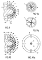
- la figure 9 est une coupe montrant une autre variante de buse selon l'invention ;
- la figure 9a est une vue de côté montrant la face intérieure de la coupelle centrale de la buse selon la figure 9 ;
- la figure 9b est une vue de côté montrant la face extérieure de la coupelle centrale de la buse selon la figure 9 ;
- la figure 10 est une coupe montrant une autre variante de buse de distribution selon l'invention ;
- la figure 10a est une vue de côté montrant la face intérieure de la coiffe, en forme de coupelle, de la buse selon la figure 10.
- Figure 1 shows, in section, a partial view of a liquid dispenser according to the invention;
- Figure 2 is a view, on a larger scale, of a detail of Figure 1;
- Figure 3 shows a variant of part of the detail of Figure 2;
- Figure 4 shows, in section, an alternative embodiment of the distribution pump fitted to a liquid distributor according to the invention;
- FIG. 5 represents, in section, the pump of FIG. 4, the piston of the pump being in a position different from that which it occupies in FIG. 4.
- Figure 6 shows, in section, a dispensing nozzle according to the invention;
- Figure 7 shows, in section, a variant of the dispensing nozzle according to Figure 6;
- FIG. 8 shows, in section, another variant of the dispensing nozzle according to the invention;
- Figure 8 a is a side view showing the inner face of the central cup of the nozzle assembly of Figure 8;
- Figure 8b is a side view showing the inner face of the peripheral cup of the nozzle according to Figure 8;
- FIG. 9 is a section showing another variant of a nozzle according to the invention;
- Figure 9 a is a side view showing the inner face of the central cup of the nozzle according to Figure 9;
- Figure 9b is a side view showing the outer face of the central cup of the nozzle according to Figure 9;
- FIG. 10 is a section showing another variant of the dispensing nozzle according to the invention;
- FIG. 10 a is a side view showing the inner face of the cap, in the form of a cup, of the nozzle according to FIG. 10.
En se reportant aux figures 1 et 2, un distributeur comprend un récipient, fermé par une coupelle 44, de manière habituelle : dès lors, l'ensemble du distributeur n'est pas représenté ; la coupelle 44 porte de manière étanche, grâce à un joint 63, une pompe classique 41 dont la tige 42 d'actionnement du piston porte, pour ce faire, un bouton-poussoir 10, et dont le tube plongeur plonge dans le liquide à distribuer que contient le récipient ; comme il est connu, la tige 42 laisse passer le liquide à distribuer lors de l'actionnement de la pompe. La pompe 41 est, par exemple, la pompe fabriquée par la société PERFECT, commercialisée sous la désignation commerciale "PZ AIRLESS".Referring to Figures 1 and 2, a dispenser comprises a container, closed by a
La coupelle 44 porte également, selon l'invention, un support de valve 46 de forme générale cylindrique, dont l'intérieur communique, par un passage 51, avec l'espace intérieur du récipient non occupé par le liquide à distribuer. Le support de valve 46 est traversé à étanchéité par une tige de commande 45 portée par le bouton-poussoir 10, parallèlement à l'axe de la pompe 41 ; la tige 45 est percée d'un canal 20.The
Le support de valve contient une bille 47, prisonnière mais pouvant se déplacer à l'intérieur, un siège conique 48 prévu à la partie supérieure de l'intérieur du support 46 étant adapté à la bille qui, lorsqu'elle coopère avec lui, empêche toute communication depuis l'intérieur du récipient vers le canal 20.The valve support contains a
La bille 47 peut être remplacée par un dispositif du type "à tiroir", comme le montre la variante de la figure 3 ; selon cette variante, l'alésage intérieur 49 du support de valve 46, de forme générale cylindrique, correspond au diamètre extérieur de la tige de commande 45, qui coulisse dans l'alésage 49 à la manière d'un tiroir ; l'alésage 49 communique avec l'intérieur du récipient par un passage 51 traversant la paroi du support 46 située en-dessous de la coupelle 44 ; le canal 20 de la tige 45 est coudé à sa partie inférieure et débouche par un orifice 52 à la surface extérieure de la tige 45. Lorsque le bouton poussoir est dans sa position de repos, l'orifice 52 est au droit de la surface intérieure de l'alésage 49, et se trouve ainsi obturé ; après une course suffisante du bouton-poussoir, donc de la tige 45, vers le bas, sur la figure 3, l'orifice 52 est en face d'une saignée 50 longitudinale prévue à la surface intérieure de l'alésage 49 et prolongeant, radialement, ledit alésage.The
Le bouton-poussoir 10 porte une buse de distribution 1 analogue à celle qui est représentée, plus détaillée, sur la figure 6.The push-
Sur la figure 6, la buse de distribution désignée dans son ensemble par le repère 1, comprend une coupelle centrale 2 emmanchée sur un embout central 3 porté par le bouton-poussoir 10 ; une chambre centrale 4 est ainsi définie par la face intérieure 5 de la coupelle centrale 2 et la face extérieure 6 de l'embout central 3. Le fond de la coupelle centrale 2 est traversé par un canal de sortie central 7, et la partie cylindrique de ladite coupelle centrale 2 est emmanchée à étanchéité en 32 à l'intérieur d'un embout périphérique 13, du support, entourant l'embout central 3 ; la coupelle centrale 2 est maintenue axialement dans l'embout périphérique 13, par exemple par clipsage en 33.In Figure 6, the dispensing nozzle designated as a whole by the
Une coupelle périphérique 11 est emmanchée sur l'embout périphérique 13, et, à étanchéité, en 34 à l'intérieur d'un embout externe 28 porté par le bouton-poussoir, l'embout externe 28 entourant l'embout périphérique 13 ; la coupelle périphérique 11 est maintenue axialement dans l'embout externe 28, par exemple par clipsage en 35. Une chambre périphérique 36 est ainsi définie entre la face intérieure 12 de la coupelle périphérique 11, la face extérieure de l'embout périphérique 13, et la face extérieure 14 de la coupelle centrale 2. La face extérieure du fond de la coupelle centrale 2 et la face intérieure du fond de la coupelle périphérique 11 sont coniques, en sorte que, les fonds des deux coupelles étant dans un même plan perpendiculaire à l'axe, un canal de sortie phériphérique 25 traversant le fond de la coupelle périphérique a, lorsque les coupelles sont montées dans le support, une forme annulaire et entoure le canal central 7.A
La chambre centrale 4 est alimentée en un liquide à distribuer par une arrivée d'alimentation 9 et un jeu 8, par exemple une saignée longitudinale dans la face intérieure de la coupelle centrale 2, entre la coupelle centrale 2 et le manchon central 3, lequel jeu 8 débouche dans un espace annulaire 9a du support, l'arrivée d'alimentation 9 débouchant dans l'espace annulaire 9a. La chambre périphérique 36 est alimentée par une arrivée d'alimentation 15, un espace annulaire 15a et une saignée longitudinale 16 ménagée sur la face intérieure de la paroi cylindrique de la coupelle périphérique 11.The central chamber 4 is supplied with a liquid to be distributed by a
Sur les figures 1 et 2, l'arrivée d'alimentation 15, au lieu d'être parallèle à l'axe de la buse 1, est perpendiculaire à cet axe, dans le prolongement du canal 20 de la tige de commande 45.In FIGS. 1 and 2, the
De manière habituelle, l'actionnement de la pompe 41 pulvérise le liquide à distribuer à travers le canal central 7 de la buse 1 via la chambre centrale 4 alimentée par l'arrivée 9 au travers de la tige 42.In the usual way, the actuation of the
Selon la présente invention, le récipient contient du gaz sous pression ; ainsi, cette même action sur le bouton-poussoir met en communication l'espace du réservoir contenant le gaz sous pression avec le canal 20, figure 2, l'alimentation 15 de la chambre périphérique 36 et donc le canal périphérique 25 : en effet, en position de repos, la tige 45 est éloignée de la bille 47 qui est plaquée, par la pression du gaz, contre son siège 48 mais, en fonctionnement de la pompe, la tige 45 décolle la bille de son siège et le gaz sous pression s'introduit dans le canal 20, grâce à des passages radiaux 20a à l'extrémité de la tige 45.According to the present invention, the container contains gas under pressure; thus, this same action on the push button puts the space in the reservoir containing the pressurized gas into communication with the
En raison de la forme conique de la chambre périphérique, ce courant de gaz vient heurter, à la sortie, le courant du liquide à distribuer sortant du canal central 7 ; cette disposition permet un meilleur fractionnement du liquide distribué, et donc une plus grande finesse de celui-ci.Due to the conical shape of the peripheral chamber, this stream of gas collides, at the outlet, with the stream of liquid to be dispensed leaving the
Les séquences de distribution de liquide à distribuer et de gaz peuvent être variées : il est, par exemple, avantageux de distribuer du gaz dans un premier temps, puis du gaz et du liquide à distribuer en même temps, et ensuite à nouveau du gaz seul, qui nettoiera par entraînement le canal central 7 grâce à la dépression créée par le courant gazeux. Ces séquences variées sont obtenues en jouant sur les longueurs relatives des tiges 42 et 45.The distribution sequences of liquid to be distributed and of gas can be varied: it is, for example, advantageous to distribute gas firstly, then gas and liquid to be distributed at the same time, and then again gas alone , which will clean by driving the
Le fractionnement du liquide distribué peut être adapté à sa nature, en adaptant notamment les canaux central 7 et périphérique 25, et/ou les chambres centrale 4 et périphérique 36.The fractionation of the dispensed liquid can be adapted to its nature, in particular by adapting the central 7 and peripheral 25 channels, and / or the central 4 and peripheral 36 chambers.
Selon la variante de la figure 7, la face extérieure du fond de la coupelle centrale 2 est en deux parties coniques 14a, 14b, l'angle de la partie 14a étant plus aigu que celui de la partie 14b ; grâce à cette disposition, le canal périphérique 25 est plus proche radialement du canal central 7.According to the variant of FIG. 7, the outer face of the bottom of the
Selon la variante de la figure 8, une précompression progressive est donnée au liquide à distribuer avant sa sortie à l'extérieur : pour celà, les chambres centrale et périphérique ont des volumes, à l'entrée, annulaires tronconiques, limités, entre autres, par les portions coniques respectivement 21 et 22 des faces internes des coupelles centrale 2 et périphérique 11. On notera, également sur cette figure, la forme hémisphérique de l'extrémité de la face extérieure de l'embout central, la partie en regard de la face intérieure 5 de la coupelle centrale 2 ayant une forme hémisphérique correspondante, laquelle face intérieure 5 de la coupelle centrale 2 étant pouvue d'ailettes hélicoïdales 23, visibles également sur la figure 8a, de manière à doter le liquide à distribuer d'un mouvement tourbillonnaire. Le canal central 7 a, ici, une forme conique convergent vers la sortie.According to the variant of FIG. 8, a progressive precompression is given to the liquid to be distributed before it leaves outside: for this, the central and peripheral chambers have volumes, at the entrance, frustoconical annulars, limited, among others, by the conical portions respectively 21 and 22 of the internal faces of the central 2 and
Selon cette même variante de la figure 8, le fond de la coupelle périphérique 11 est plat, ainsi que la face extérieure de la coupelle centrale 2 située en regard ; la face intérieure du fond de la coupelle périphérique 11 est munie d'ailettes 24, également visibles sur la figure 8b ; ces ailettes 24 sont planes, selon des plans parallèles à l'axe mais ne passant pas par l'axe, et inclinées d'un même angle et dans le même sens par rapport aux rayons qui passent par leur extrémité la plus éloignée de l'axe : cette disposition permet de doter le gaz, également, d'un mouvement tourbillonnaire ; on notera que les tourbillons de liquide à distribuer et de gaz sont en sens opposés de manière à augmenter le fractionnement. Dans l'exemple de la figure 8, le canal périphérique est formé de deux troncs de cônes, l'un, 25A, convergent, et l'autre, 25B, divergent, l'extrémité plane perpendiculaire à l'axe de la sortie du canal central étant disposée au droit du plan de raccordement des deux troncs de cônes 25A, 25B.According to this same variant of Figure 8, the bottom of the
La variante de buse représentée sur la figure 9, comporte les dispositions avantageuses de la figure 8, à savoir précompression des fluides grâce aux formes tronconiques 21, 22 des faces internes des coupelles, ainsi que mouvements tourbillonnaires des fluides ; selon cette variante, les ailettes 26, 27 provoquant ces mouvements tourbillonnaires sont toutes portées par le fond de la coupelle centrale : ces ailettes sont du type décrit selon la figure 8b ; les ailettes 26 sont prévues sur la face interne de la coupelle centrale 2 et visibles également sur la figure 9a, vue de la gauche de la figure 9, et les ailettes 27 sont prévues sur la face externe de la coupelle centrale 2 et visibles également sur la figure 9b, vue de la droite de la figure 9.The variant of nozzle shown in FIG. 9 includes the advantageous arrangements of FIG. 8, namely precompression of fluids thanks to the frustoconical shapes 21, 22 of the internal faces of the cups, as well as swirling movements of the fluids; according to this variant, the
La variante de la figure 9 est également avantageuse de par la disposition relative et la constitution des canaux central et périphérique. Le canal central est conique convergent vers l'extérieur en 7a, et le canal périphérique conique divergent vers l'extérieur en 25b ; les deux troncs de cônes 7a et 25b sont séparés par un espace 7b dans lequel les fluides se rencontrent ; cette disposition en venturi provoque la compression du liquide à distribuer en 7a, la rencontre du liquide à distribuer et du gaz en 7b, la dépression du mélange en 25b, et favorise la finesse et l'homogénéité de la pulvérisation.The variant of Figure 9 is also advantageous by the relative arrangement and the constitution of the central and peripheral channels. The central channel is conical converging outwardly 7a, and the conical peripheral channel diverge outwardly in 25 b; the two trunks of
La variante de buse selon la figure 10, et partiellement la figure 10a, est analogue à celle de la figure 9, à laquelle a été ajoutée une coiffe 37 en forme de coupelle ; la coiffe 37 est constituée d'une jupe cylindrique 38 et d'une calotte sphérique 39, raccordées par des nervures radiales 30. La jupe 38 est emmanchée à étanchéité, d'une part, sur la face extérieure cylindrique de la coupelle périphérique 11 clipsée en 35 et, d'autre part, à l'intérieur de l'embout externe 28, clipsée en 40, également à étanchéité. L'espace compris entre la face intérieure de la calotte 39 et la face extérieure de la coupelle périphérique 11 définit une pluralité de canaux coniques convergents vers l'extérieur, la face extérieure de la coupelle étant prévue conique selon 29 sur la figure 9 ; ces canaux répartis conférentiellement autour de l'axe débouchent de part et d'autre à l'extérieur, en ayant une entrée, éloignée de l'axe, plus large que la sortie proche de l'axe ; une sortie annulaire 31 est ainsi définie ; cette sortie 31 entoure la sortie du canal périphérique 25b et est proche de celle-ci ; grâce à cette disposition, la dépression régnant à la sortie du venturi 7a, 7b, 25b aspire de l'air extérieur qui traverse ces canaux et vient également fractionner et aérer le liquide pulvérisé.The variant nozzle according to FIG. 10, and partially FIG. 10a, is similar to that of FIG. 9, to which a
Les variantes de buse de distribution décrites en référence aux figures 6 à 10a s'appliquent quelle que soit la pompe de distribution équipant le distributeur selon l'invention. Elles s'appliquent également à la pompe de distribution, selon également la présente invention, notamment celle décrite en référence aux figures 4 et 5.The dispensing nozzle variants described with reference to FIGS. 6 to 10a apply regardless of the dispensing pump fitted to the dispenser according to the invention. They also apply to the distribution pump, also according to the present invention, in particular that described with reference to FIGS. 4 and 5.
Sur la figure 4, la pompe 60, selon l'invention, comporte un corps de pompe 69 cylindrique ; à l'extrémité supérieure de ce corps de pompe 69 est assujettie, par exemple par clipsage, une manchette 61 qui est maintenue sur le récipient par une coupelle 62, par l'intermédiaire d'une rondelle d'étanchéité 63. Le bouton-poussoir 10 de la pompe est monté coulissant le long de la paroi extérieure de la manchette 61, qui est en forme générale de chapeau, dont le fond est traversé, en son centre, par une tige creuse 18 de piston, solidarisée au bouton-poussoir 10 ; l'intérieur 19 de la tige creuse 18 communique, par une arrivée 9 d'alimentation, avec la chambre centrale 4 de la buse de distribution 1 portée par le bouton-poussoir 10. Le piston, par sa lèvre d'étanchéité 67a, coulisse à l'intérieur du corps 69, et porte une chaussette cylindrique 67 entourant la tige de piston 18, et s'étendant à l'opposé du joint d'étanchéité.In Figure 4, the
La manchette 61 porte une jupe cylindrique 17 entourant également la tige de piston 18, mais située à l'intérieur de la chaussette 67 du piston ; l'extrémité 68 de la chaussette 67, en forme de lèvre, coopère à étanchéité avec la face extérieure de la jupe, au moins sur une longueur axiale de celle-ci.The
Une première valve 76 comprend une première partie allongée s'étendant à l'intérieur de la tige de piston 18 et portant une partie conique 76a destinée à s'appliquer sur un siège 18a constitué par le rebord d'une courte partie cylindrique creuse ménagée dans le perçage 19 : un ressort 71 coopère avec une deuxième partie allongée de la première valve 76 qui s'étend à l'extérieur de la tige de piston 18.A
Une deuxième valve 72 entoure la deuxième partie allongée de la première valve 76 ; de forme cylindrique, la deuxième valve porte, à une extrémité, une partie conique 75 destinée à coopérer avec un siège conique complémentaire 78 porté par une partie élargie de la première valve 76, située entre ses deux parties allongées. A l'extrémité opposée à celle qui porte la partie conique 75, la deuxième valve 72 est munie d'une portée d'étanchéité 73 destinée à coopérer, à étanchéité, avec la surface extérieure d'un manchon tubulaire d'étanchéité 74, prévu dans le support 69 coaxialement, la surface extérieure du manchon 74 et la face intérieure du support se raccordant à l'extrémité inférieure du support 69. Le prolongement d'un talon creux 70 permet de raccorder au support 69 un tube plongeur, comme habituellement.A
Le récipient contenant du gaz sous pression, les éléments constitutifs de la pompe sont représentés à la figure 4 dans la position de repos, le bouton-poussoir 10 n'étant soumis à aucune action. Dans cette position, le volume compris en dessous du siège 18a dans la tige de piston, le corps de pompe sous le joint de piston 67a et le tube plongeur sont remplis de liquide à distribuer : le ressort 71 applique la première valve 76 sur le siège 18a, et le liquide, sous la pression du gaz sous pression contenu dans le récipient, remonte l'ensemble piston-première valve-bouton-poussoir vers le haut jusqu'à ce que l'extrémité 68 de la chaussette 67 vienne buter contre le bord de la manchette 61 ; des portées complémentaires de sécurité et d'étanchéité sont en outre prévues sur le bouton-poussoir et la manchette, respectivement intérieure 10a, et extérieure 61a ; la deuxième valve 72 repose, par gravité, sur les premières spires du ressort 71 qui entourent la deuxième partie allongée de la première valve en débordant sa surface extérieure, ici amincie pour définir l'appui du ressort sur la première valve 76 ; dans cette position, la portée 73 de la deuxième valve est à distance du manchon 74.The container containing gas under pressure, the constituent elements of the pump are shown in FIG. 4 in the rest position, the push-
Le gaz sous pression est retenu par la coopération de l'extrémité 68 de la chaussette 67 avec la face externe de la jupe 17 : en effet, le gaz sous pression est présent autour du corps 69 et à l'intérieur de la coupelle 62, passe en 63a la rondelle 63, un espace continu 64 et localisé en 65 entre le corps 69 et la manchette 61, puis un passage 66 prévu sur le rebord supérieur du corps 69 face au fond de la manchette 61.The pressurized gas is retained by the cooperation of the
Une action sur le bouton-poussoir 10 est transmise à la tige de piston 18 et à la première valve 76 ; la deuxième valve, dans un premier temps, vient en appui par sa portée 73 sur le bord du siège 74 constitué par le manchon d'étanchéité et, dans un deuxième temps, vient, par sa partie conique 75, en appui sur le siège 78, ce par quoi lui est transmis l'effort appliqué au bouton-poussoir 10. A partir de cet instant, une chambre de compression est créée, enfermant du liquide entre le corps de pompe et le piston ; la descente du bouton-poussoir étant poursuivie, la distribution du liquide, sous la pression de la pompe, par le canal 7, via les passages 9 et 19 est obtenue comme habituellement, l'effort dû à la pression sur la section 76a s'opposant à celui du ressort 71 pour alors ouvrir la première valve 76.An action on the push-
Selon l'invention, après une course définie par les longueurs axiales respectives de la chaussette 67 et de la jupe 17 et de la position d'une portion 17a de plus petit diamètre de la jupe 17, la lèvre 68 de la chaussette n'assure plus l'étanchéité du gaz sous pression, et celui-ci est amené à la chambre périphérique de la buse 1 via le passage circulaire 20 entre la jupe 17 et la tige 18, l'intérieur du bouton-poussoir monté en 10a et 61a à étanchéité sur la manchette 61. La fin de course du bouton-poussoir et des éléments de la pompe est montrée à la figure 5.According to the invention, after a stroke defined by the respective axial lengths of the
Claims (6)
Applications Claiming Priority (2)
| Application Number | Priority Date | Filing Date | Title |
|---|---|---|---|
| FR929203352A FR2688714B1 (en) | 1992-03-20 | 1992-03-20 | LIQUID DISPENSER HAVING A DISPENSING PUMP AND DISPENSING PUMP FOR SUCH A DISPENSER. |
| FR9203352 | 1992-03-20 |
Publications (2)
| Publication Number | Publication Date |
|---|---|
| EP0561666A1 true EP0561666A1 (en) | 1993-09-22 |
| EP0561666B1 EP0561666B1 (en) | 1997-11-19 |
Family
ID=9427879
Family Applications (1)
| Application Number | Title | Priority Date | Filing Date |
|---|---|---|---|
| EP93400572A Expired - Lifetime EP0561666B1 (en) | 1992-03-20 | 1993-03-05 | Liquid dispenser with a delivery pump and delivery pump for this dispenser |
Country Status (6)
| Country | Link |
|---|---|
| EP (1) | EP0561666B1 (en) |
| JP (1) | JPH07256161A (en) |
| CA (1) | CA2092063C (en) |
| DE (1) | DE69315243T2 (en) |
| ES (1) | ES2109446T3 (en) |
| FR (1) | FR2688714B1 (en) |
Cited By (2)
| Publication number | Priority date | Publication date | Assignee | Title |
|---|---|---|---|---|
| NL2020054B1 (en) * | 2017-12-12 | 2019-06-21 | Protix Bv | Centralized system for distributing olfactory triggers for ovipositioning to insect breeding enclosures |
| US11382323B2 (en) | 2017-04-04 | 2022-07-12 | Protix B.V. | Centralized system for distributing olfactory triggers for ovipositioning to insect breeding enclosures |
Families Citing this family (1)
| Publication number | Priority date | Publication date | Assignee | Title |
|---|---|---|---|---|
| CN110589208A (en) * | 2019-08-12 | 2019-12-20 | 浙江正庄实业有限公司 | Improved pump core and preparation method of environment-friendly high-tech material thereof |
Citations (3)
| Publication number | Priority date | Publication date | Assignee | Title |
|---|---|---|---|---|
| EP0307310A1 (en) * | 1987-09-09 | 1989-03-15 | VALOIS Société Anonyme dite: | Spray device of the precompression hand pump type for use with a propelling gas |
| EP0309010A1 (en) * | 1987-07-08 | 1989-03-29 | Ing. Erich Pfeiffer GmbH & Co. KG | Manual fluid dispenser |
| EP0451615A2 (en) * | 1990-04-10 | 1991-10-16 | Ing. Erich Pfeiffer GmbH & Co. KG | Discharge device for at least one medium |
-
1992
- 1992-03-20 FR FR929203352A patent/FR2688714B1/en not_active Expired - Fee Related
-
1993
- 1993-03-05 ES ES93400572T patent/ES2109446T3/en not_active Expired - Lifetime
- 1993-03-05 EP EP93400572A patent/EP0561666B1/en not_active Expired - Lifetime
- 1993-03-05 DE DE69315243T patent/DE69315243T2/en not_active Expired - Fee Related
- 1993-03-19 CA CA002092063A patent/CA2092063C/en not_active Expired - Fee Related
- 1993-03-22 JP JP5085154A patent/JPH07256161A/en active Pending
Patent Citations (3)
| Publication number | Priority date | Publication date | Assignee | Title |
|---|---|---|---|---|
| EP0309010A1 (en) * | 1987-07-08 | 1989-03-29 | Ing. Erich Pfeiffer GmbH & Co. KG | Manual fluid dispenser |
| EP0307310A1 (en) * | 1987-09-09 | 1989-03-15 | VALOIS Société Anonyme dite: | Spray device of the precompression hand pump type for use with a propelling gas |
| EP0451615A2 (en) * | 1990-04-10 | 1991-10-16 | Ing. Erich Pfeiffer GmbH & Co. KG | Discharge device for at least one medium |
Cited By (2)
| Publication number | Priority date | Publication date | Assignee | Title |
|---|---|---|---|---|
| US11382323B2 (en) | 2017-04-04 | 2022-07-12 | Protix B.V. | Centralized system for distributing olfactory triggers for ovipositioning to insect breeding enclosures |
| NL2020054B1 (en) * | 2017-12-12 | 2019-06-21 | Protix Bv | Centralized system for distributing olfactory triggers for ovipositioning to insect breeding enclosures |
Also Published As
| Publication number | Publication date |
|---|---|
| ES2109446T3 (en) | 1998-01-16 |
| FR2688714B1 (en) | 1994-06-17 |
| EP0561666B1 (en) | 1997-11-19 |
| CA2092063C (en) | 1999-01-12 |
| DE69315243T2 (en) | 1998-03-19 |
| JPH07256161A (en) | 1995-10-09 |
| FR2688714A1 (en) | 1993-09-24 |
| CA2092063A1 (en) | 1993-09-21 |
| DE69315243D1 (en) | 1998-01-02 |
Similar Documents
| Publication | Publication Date | Title |
|---|---|---|
| EP0734969B1 (en) | Aerosol dispenser with two spray nozzles | |
| EP1268083B1 (en) | Dispensing member with outlet valve formed by a differential piston | |
| CA2163483C (en) | Precompression manual pump for liquid pulverizing and dispensing assembly equipped with such pump | |
| CA2152147C (en) | Pre-compression manual pump for spraying a liquid and dispensing assembly equipped with such pump | |
| EP0747131B1 (en) | Pumping device for removing liquid from a container and for spraying it | |
| FR2656900A1 (en) | MANUAL PRECOMPRESSION PUMP FOR SPRAYING A LIQUID, ESPECIALLY A PERFUME. | |
| CA2360883C (en) | Spraying device having at least two exhaust ports for carrier gas | |
| EP1606192B1 (en) | Product distributor comprising a pump operated by a plunger | |
| CA2407213C (en) | Spraying device for application of at least on product on a substrate, namely a keratenized substrate such as skin | |
| EP1867396A1 (en) | Spray gun for painting using aerosol cartridges | |
| EP0000313A1 (en) | Pressure accumulative spraying pump and spray head | |
| EP0544549B1 (en) | Pump for the delivery of a product, liquid or paste-like, and dispenser-container with such a pump | |
| EP0658490B1 (en) | Depressible valve for vaporising a liquid and pressurised container provided with such a valve | |
| EP0561666B1 (en) | Liquid dispenser with a delivery pump and delivery pump for this dispenser | |
| EP1616632B1 (en) | Pump to spray a product in different positions and container therefor | |
| FR2699835A1 (en) | Kit for spraying a liquid comprising a precompression pump. | |
| EP0561696B1 (en) | Dispensing nozzle | |
| CH625019A5 (en) | ||
| FR2705323A1 (en) | Spray valve for aerosol container, and aerosol container equipped with such a valve | |
| EP0499537B1 (en) | Spraying or dispensing device for a fluid product comprising a sliding dip tube in its inlet port | |
| EP2279795B1 (en) | System for dispensing a fluid product | |
| FR2708908A1 (en) | Push-button with a spray nozzle intended for mounting on a dispenser and dispenser fitted with such a push-button | |
| EP0518723B1 (en) | Method and device for dispensing a viscous gel | |
| FR2779185A1 (en) | pump for liquids or paste, |
Legal Events
| Date | Code | Title | Description |
|---|---|---|---|
| PUAI | Public reference made under article 153(3) epc to a published international application that has entered the european phase |
Free format text: ORIGINAL CODE: 0009012 |
|
| 17P | Request for examination filed |
Effective date: 19930308 |
|
| AK | Designated contracting states |
Kind code of ref document: A1 Designated state(s): DE ES FR GB IT |
|
| 17Q | First examination report despatched |
Effective date: 19950726 |
|
| GRAG | Despatch of communication of intention to grant |
Free format text: ORIGINAL CODE: EPIDOS AGRA |
|
| GRAH | Despatch of communication of intention to grant a patent |
Free format text: ORIGINAL CODE: EPIDOS IGRA |
|
| GRAH | Despatch of communication of intention to grant a patent |
Free format text: ORIGINAL CODE: EPIDOS IGRA |
|
| GRAA | (expected) grant |
Free format text: ORIGINAL CODE: 0009210 |
|
| AK | Designated contracting states |
Kind code of ref document: B1 Designated state(s): DE ES FR GB IT |
|
| ITF | It: translation for a ep patent filed |
Owner name: JACOBACCI & PERANI S.P.A. |
|
| GBT | Gb: translation of ep patent filed (gb section 77(6)(a)/1977) |
Effective date: 19971119 |
|
| REF | Corresponds to: |
Ref document number: 69315243 Country of ref document: DE Date of ref document: 19980102 |
|
| REG | Reference to a national code |
Ref country code: ES Ref legal event code: FG2A Ref document number: 2109446 Country of ref document: ES Kind code of ref document: T3 |
|
| PLBE | No opposition filed within time limit |
Free format text: ORIGINAL CODE: 0009261 |
|
| STAA | Information on the status of an ep patent application or granted ep patent |
Free format text: STATUS: NO OPPOSITION FILED WITHIN TIME LIMIT |
|
| 26N | No opposition filed | ||
| PGFP | Annual fee paid to national office [announced via postgrant information from national office to epo] |
Ref country code: DE Payment date: 19991231 Year of fee payment: 8 |
|
| PGFP | Annual fee paid to national office [announced via postgrant information from national office to epo] |
Ref country code: GB Payment date: 20000301 Year of fee payment: 8 |
|
| PGFP | Annual fee paid to national office [announced via postgrant information from national office to epo] |
Ref country code: FR Payment date: 20000310 Year of fee payment: 8 |
|
| PGFP | Annual fee paid to national office [announced via postgrant information from national office to epo] |
Ref country code: ES Payment date: 20000322 Year of fee payment: 8 |
|
| PG25 | Lapsed in a contracting state [announced via postgrant information from national office to epo] |
Ref country code: GB Free format text: LAPSE BECAUSE OF NON-PAYMENT OF DUE FEES Effective date: 20010305 |
|
| PG25 | Lapsed in a contracting state [announced via postgrant information from national office to epo] |
Ref country code: ES Free format text: LAPSE BECAUSE OF NON-PAYMENT OF DUE FEES Effective date: 20010306 |
|
| GBPC | Gb: european patent ceased through non-payment of renewal fee |
Effective date: 20010305 |
|
| PG25 | Lapsed in a contracting state [announced via postgrant information from national office to epo] |
Ref country code: FR Free format text: LAPSE BECAUSE OF NON-PAYMENT OF DUE FEES Effective date: 20011130 |
|
| REG | Reference to a national code |
Ref country code: FR Ref legal event code: ST |
|
| PG25 | Lapsed in a contracting state [announced via postgrant information from national office to epo] |
Ref country code: DE Free format text: LAPSE BECAUSE OF NON-PAYMENT OF DUE FEES Effective date: 20020101 |
|
| REG | Reference to a national code |
Ref country code: ES Ref legal event code: FD2A Effective date: 20030203 |
|
| PG25 | Lapsed in a contracting state [announced via postgrant information from national office to epo] |
Ref country code: IT Free format text: LAPSE BECAUSE OF NON-PAYMENT OF DUE FEES;WARNING: LAPSES OF ITALIAN PATENTS WITH EFFECTIVE DATE BEFORE 2007 MAY HAVE OCCURRED AT ANY TIME BEFORE 2007. THE CORRECT EFFECTIVE DATE MAY BE DIFFERENT FROM THE ONE RECORDED. Effective date: 20050305 |