EP0562402A1 - Plate for coverings, especially for heavy duty floor coverings, and covering produced with this plate - Google Patents
Plate for coverings, especially for heavy duty floor coverings, and covering produced with this plate Download PDFInfo
- Publication number
- EP0562402A1 EP0562402A1 EP93104158A EP93104158A EP0562402A1 EP 0562402 A1 EP0562402 A1 EP 0562402A1 EP 93104158 A EP93104158 A EP 93104158A EP 93104158 A EP93104158 A EP 93104158A EP 0562402 A1 EP0562402 A1 EP 0562402A1
- Authority
- EP
- European Patent Office
- Prior art keywords
- plate
- projection
- projections
- usable
- coverings
- Prior art date
- Legal status (The legal status is an assumption and is not a legal conclusion. Google has not performed a legal analysis and makes no representation as to the accuracy of the status listed.)
- Withdrawn
Links
Images


Classifications
-
- E—FIXED CONSTRUCTIONS
- E04—BUILDING
- E04F—FINISHING WORK ON BUILDINGS, e.g. STAIRS, FLOORS
- E04F13/00—Coverings or linings, e.g. for walls or ceilings
- E04F13/07—Coverings or linings, e.g. for walls or ceilings composed of covering or lining elements; Sub-structures therefor; Fastening means therefor
- E04F13/08—Coverings or linings, e.g. for walls or ceilings composed of covering or lining elements; Sub-structures therefor; Fastening means therefor composed of a plurality of similar covering or lining elements
- E04F13/18—Coverings or linings, e.g. for walls or ceilings composed of covering or lining elements; Sub-structures therefor; Fastening means therefor composed of a plurality of similar covering or lining elements of organic plastics with or without reinforcements or filling materials or with an outer layer of organic plastics with or without reinforcements or filling materials; plastic tiles
-
- E—FIXED CONSTRUCTIONS
- E04—BUILDING
- E04F—FINISHING WORK ON BUILDINGS, e.g. STAIRS, FLOORS
- E04F15/00—Flooring
- E04F15/02—Flooring or floor layers composed of a number of similar elements
- E04F15/02172—Floor elements with an anti-skid main surface, other than with grooves
-
- E—FIXED CONSTRUCTIONS
- E04—BUILDING
- E04F—FINISHING WORK ON BUILDINGS, e.g. STAIRS, FLOORS
- E04F15/00—Flooring
- E04F15/02—Flooring or floor layers composed of a number of similar elements
- E04F15/10—Flooring or floor layers composed of a number of similar elements of other materials, e.g. fibrous or chipped materials, organic plastics, magnesite tiles, hardboard, or with a top layer of other materials
Definitions
- the invention relates to a plate for coverings, in particular for heavy-duty floor coverings, according to the preamble of claim 1 and a plate covering produced with this plate according to the preamble of claim 7.
- Highly resistant floor coverings for example for industrial use, which are stressed by heavy machinery and vehicles such as forklifts, but also by chemicals or moisture, are required for the construction and renovation, possibly in connection with a change of use, of buildings.
- the object of the invention is therefore seen in proposing a plate for coverings, in particular heavy-duty floor coverings of the type mentioned at the outset, and a floor covering produced with this plate.
- the object is achieved by a plate of the type mentioned at the beginning, which is defined by the characterizing part of patent claim 1, and a plate covering produced with this plate, which is defined by the characterizing part of patent claim 6.
- the plates Thanks to the formation of the projections on the usable surface, which rest on the projections on the system side, the plates have a pressure-distributing effect. They can therefore be installed on an uneven old floor without fastening, for example by gluing or with additional fixing elements, and form a flat floor covering without the need to level the old floor beforehand. Since the plates are connected to one another or guided together at their edge regions by the projections, they do not move away from the plate assembly forming the base even if they have to absorb forces other than vertical forces.
- Particularly advantageous plates and plate coverings are obtained by combining the advantages of the new plate shape with the advantages of a plate material made of highly compressed plastic; As this is largely chemically resistant, the panels can also be laid on a dirty or damp surface, for example in new buildings without drying the sub-floor. Sheets made of highly compressed thermoplastic serve both as underlay and as flooring and have a vapor barrier function.
- the problems which occur in known floor covering boards as a result of temperature differences within the floor covering do not exist in the inventive boards made of thermoplastic material due to the combination of the boards with the thermoplastic properties.
- Panel coverings with the new panels and especially made of highly compressed plastic are therefore suitable thanks to their Design and its material properties for floor coverings that have to meet the highest chemical and mechanical requirements, i.e. for all types of industrial buildings.
- the new panels have been specially developed for industrial floor coverings, they can also be used for wall and ceiling coverings, both in industrial buildings and in public and private buildings.
- Panels in the new form can be produced in a simple manner, as mentioned, without additional fixing elements and, in the event of damage to individual panels or during a later building renovation, they can also be easily removed individually or in their entirety and, if necessary, recycled as recycling material.
- the panels can be used not only on uneven sub-floors, but also on a grid-like surface, e.g. can be laid over cable or pipe ducts and, with a suitable choice of material, also over pipe systems of floor heating or cooling systems as well as outdoors.
- the overlapping projections on the usable area and the engaging projections on the plant side must be of the same width.
- the grooves and tongues that form the fastening elements can have rectangular cross sections or can be tapered. It is particularly favorable to provide roundings in the base of the groove; the plate part above or below the groove base, which is the thinnest and weakest part of the plate, can be protected against breakage there easily arise due to the notch effects caused by protruding edges.
- the new slabs are shaped in such a way that at least their usable areas are straight-lined polygons that can be laid across the entire surface. Although triangular or hexagonal slab shapes are also possible, slabs with rectangular usable areas, in particular with even-numbered ratios of length and width, are particularly simple to manufacture or to lay in various arrangements.
- the plates are preferably designed in such a way that they have mutually opposite, parallel edge regions, one of which is arranged on the usable surface side and the other on the plant side, so that the plates are rotationally symmetrical with respect to the parallel plate center axis.
- Such plates result in an optimal pressure equalization and the possibility to get by with a single plate shape.
- parts of the system-side projections can be omitted in order to save material and / or to reduce the weight. It is also possible to provide the panels with recesses on the system side.
- Joints are occasionally required, for example to reduce the risk of slipping or to facilitate the replacement of damaged panels; for this purpose, the overlapping flange-like projections of the usable areas across the plate edge must be narrower than the under-engaging projections of the contact surfaces, so that joints are created between the usable areas of adjacent panels. Rectangular panels can be laid so that their edges are aligned in both surface dimensions, which makes it easier to replace individual panels. However, you can achieve a higher load-bearing capacity of the slab covering if you move adjacent rows of slabs alongside one another along part of their length.
- the adaptation of a panel covering to a certain building size is done either by cutting the edge panels or by filling an edge joint, for example with a silicone compound or by covering the edge joint with an edge strip made of a flexible or rigid material.
- the plates are easily removed from the large plates or strips by thermal cutting or other separation processes.
- the plate material can also be machined like soft metal or wood.
- the highly compressed plastic material can be produced in different colors, so that patterns can be created when laying or transport routes and danger areas can be identified by panels of a different color.
- an additive can be added to the material, which largely prevents a static charge on the plate coverings.
- the surfaces of the plates are smooth and can therefore be easily cleaned.
- the plates made of this plastic are homogeneous, so that on the material side there is no difference between an upper and a lower plate layer or between the usable and the contact surface. For this reason it is also possible to clean the plates with abrasive agents or to grind them completely.
- Panels made from this material are largely chemically resistant and flame-retardant. They can therefore be used in buildings for chemical production facilities and laboratories but also in hospitals and they can be used especially on old floors that are contaminated by residues of chemically aggressive substances.
- the panels made of the high-density plastic are moisture-resistant and can therefore be laid on a damp surface, even without a vapor barrier, for example, as already mentioned, on a non-dried floor of a new building, where the moisture can escape laterally.
- the plates are also suitable for wet areas and can of course be easily cleaned wet.
- the panels made of the material mentioned are frost-proof so that they can be laid outdoors.
- the thermal properties of the board material are such that the boards can be laid directly on the pipe systems of heating or cooling systems. As the elasticity of thermoplastic panels is also increased during heating, the panels can also be installed at low temperatures.
- Panels made of this material are practically neutral in terms of their strength properties at least and can therefore be laid in any orientation if their shape is selected accordingly.
- Adjacent plates made of highly compressed plastic can be thermally welded together in a simple manner.
- an absolutely liquid-tight floor covering is required, for example to prevent the seepage or rising of water or environmentally harmful substances, there can be a difference between the individual plates are given a small amount of a non-adhesive sealant.
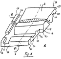
- the plate 2 in FIGS. 1 and 2 has a rectangular usable surface 4 and a congruent contact surface 6 oriented parallel thereto.
- the upper, that is to say usable, edge regions of the plate 2 on the right and rear in FIG. 1 are designed as flange-like projections 8 and 10, and their surface forms part of the usable surface 4.
- the lower, on the left and in front in FIG. 1, are accordingly , that is to say the edge regions of the plate 2 on the system side are designed as flange-like projections 12 and 14, and their lower surface forms part of the contact surface 6.
- the projection 8 has, on its surface opposite the usable surface 4, 16 fastening members 17 which are designed as follows: a groove parallel to the plate edge 18 extends along the entire projection 8. The cross section of this groove 18 is rectangular.
- the groove-free edge strip of the surface 16 becomes a rib which extends along the projection 9e and which, as will be described later, acts as a tongue in conjunction with a groove of an adjacent plate and is also referred to as tongue 20.
- the projections 10, 12 and 14 have corresponding grooves 22, 26 and 30 and corresponding springs 24, 28 and 32.
- the plate 2 is thus rotationally symmetrical with respect to its plate center axes l and k.
- the projections 8 and 10 on the usable surface extend over the entire length of the corresponding edge regions of the usable surface 4 or the contact surface 6, and the grooves 18, 22, 26, 30 and the springs 20, 24 , 28, 32 of the upper and lower projections 8, 10, 12, 14 continue up to corner portions 34 and 36 respectively.
- a first slab 2 is laid. Further panels are laid, to a certain extent, like roof tiles, continuously to the left and front thereof, so that the upper projections 8 and 10 of the further panels are supported on the lower projections 12 and 14 of the panels that have already been installed. As a result, vertical forces acting on a plate are partially transmitted to at least two of the adjacent plates. In a way, this achieves a vertical pressure distribution, i.e. to compensate for uneven stress caused by uneven ground and high loads, for example from heavy machinery.
- the grooves 18 or 22 or 26 or 30 and springs 20 or 24 or 28 or 32 form a novel tongue and groove connection, by means of which Plates arranged next to one another are guided parallel to one another so that a relative movement transverse to their edges is prevented.
- the result of this is that horizontal forces or force components are transmitted from one plate to a part of the adjacent plates, which to a certain extent results in a horizontal pressure distribution in both directions across the plate edges; this is particularly favorable when there are strong bumps in the ground and on floors that are driven on by vehicles, for example trucks with high accelerations and speeds of rotation.
- Fig. 3 shows a similar plate 42 as the plate 2 shown in Figs. 1 and 2, with a different design of the tongue and groove connection, which form fastening members 44.
- plates 42 are not rotationally symmetrical With regard to their central axes, a covering can be created with plates, which are all of the same shape.
- FIG. 4 shows plates 52 which are shaped in such a way that in the plate assembly, at least on the usable surface side, joints 54 are formed between adjacent plates 52, which are filled with a suitable mass 56. If the expected thermal dilatation is high, you can also provide joints on the system side and choose elastic fillers.
- FIG. 5 shows plates 62 in which the cross sections of grooves 64 and springs 66 forming fastening elements are tapered and their edges are rounded. This makes laying easier and reduces the risk of breakage in the area of the protruding edges 68 of the groove base, since the notch effect is reduced by the rounding.
- FIG. 7 shows another laying pattern in which the edges of the usable areas 4 are only aligned in one dimension.
- the durability is higher than with a laying pattern according to FIG. 6, but replacing a damaged plate 2 is more difficult.
- Fig. 8 shows a plate covering with hexagonal plates 72.
- Such plate coverings are very durable, but the manufacture of the plates 72 and the laying are more complex in comparison with rectangular plates 2.
- FIG. 9 shows a light panel for low loads, in which parts 74 of the edge regions on the system side are omitted and the recesses 76 on the system side have. This saves material and weight, while reducing strength and pressure distribution.
Abstract
Description
Die Erfindung betrifft eine Platte für Beläge, insbesondere für hochbeanspruchbare Bodenbeläge, nach dem Oberbegriff des Patentanspruchs 1 und einen mit dieser Platte hergestellten Plattenbelag nach dem Oberbegriff des Patentanspruchs 7.The invention relates to a plate for coverings, in particular for heavy-duty floor coverings, according to the preamble of claim 1 and a plate covering produced with this plate according to the preamble of claim 7.
Hochresistente Bodenbeläge, zum Beispiel für industriellen Gebrauch, die durch schwere Maschinen und Fahrzeuge wie Stapler aber auch durch Chemikalien oder Feuchtigkeit beansprucht sind, werden bei der Erstellung und bei der Sanierung, ggfs. in Verbindung mit einer Umnutzung, von Bauten benötigt.Highly resistant floor coverings, for example for industrial use, which are stressed by heavy machinery and vehicles such as forklifts, but also by chemicals or moisture, are required for the construction and renovation, possibly in connection with a change of use, of buildings.
Die Anforderungen, die vom Benützer an solche Bodenbeläge gestellt werden, sind im wesentlichen hohe mechanische Festigkeit, gute chemische Resistenz und einfache Unterhaltsmöglichkeiten sowie keine nachteiligen Folgen von Wärmedilatationen bei Verwendung in grossen Räumen mit hohen Temperaturschwankungen.The requirements that the user places on such floor coverings are essentially high mechanical strength, good chemical resistance and simple maintenance options, and no adverse consequences of thermal dilatation when used in large rooms with high temperature fluctuations.
Weitere Anforderungen sind zu erfüllen, wenn die Bodenbeläge bei der Sanierung von Altbauten verwendet werden. Der vorhandene Untergrund oder Altboden, welchen man aus Kostengründen wenn möglich belässt, ist im allgemeinen infolge ungleichmässiger Abnützung nicht mehr plan und ausserdem oft verschmutzt, zum Beispiel durch Teer- und Oelreste und gelegentlich durch Klebstoffreste früherer Bodenbeläge.Additional requirements must be met if the flooring is used for the renovation of old buildings. The existing subsoil or old floor, which should be left as possible for reasons of cost, is generally no longer flat due to uneven wear and is also often dirty, e.g. from tar and oil residues and occasionally from adhesive residues from previous floor coverings.
Bis heute werden solche Altböden vor allem auf zwei Arten saniert:
Bei der ersten Art wird durch ein Ausgiessen ein neuer Bodenbelag erstellt, wodurch auch die vorhandenen Unebenheiten möglichst ausgeglichen werden. Der Nachteil dieses Systems liegt vor allem darin, dass anschliessend eine Trocknungs- oder Aushärtungsfrist von mehreren Wochen verstreichen muss, bis der neue Belag benutzt werden kann, was zu einer Erhöhung der Baukosten führt.To date, old floors of this type are mainly renovated in two ways:
In the first type, a new floor covering is created by pouring, which also compensates for any unevenness. The main disadvantage of this system is that a drying or curing period of several weeks must then pass before the new covering can be used, which leads to an increase in construction costs.
Bei der zweiten Art, Altböden zu sanieren, wird ein neuer Belag aufgeklebt. Nachteilig ist dabei, dass die Haftung schlecht ist, wenn die Böden verschmutzt sind. Ausserdem werden die Unebenheiten nur zum Teil ausgeglichen, vor allem bei der Verwendung der üblichen, verhältnismässig dünnen, flexiblen Kunststoffplatten, welche miteinander durch Befestigungsorgane verbindbar sind, die durch ihre in Draufsicht schwalbenschwanzartigen Randbereiche gebildet werden.In the second way of renovating old floors, a new covering is glued on. The disadvantage is that the adhesion is poor when the floors are dirty. In addition, the unevenness is only partially compensated for, especially when using the usual, relatively thin, flexible plastic plates which can be connected to one another by fastening members which are formed by their dovetail-like edge regions in plan view.
Die Aufgabe der Erfindung wird somit darin gesehen, eine Platte für Beläge, insbesondere hochbeanspruchbare Bodenbeläge der eingangs genannten Art sowie einen mit dieser Platte hergestellten Bodenbelag vorzuschlagen.The object of the invention is therefore seen in proposing a plate for coverings, in particular heavy-duty floor coverings of the type mentioned at the outset, and a floor covering produced with this plate.
Die Lösung der Aufgabe bildet erfindungsgemäss eine Platte der eingangs genannten Art, welche durch den kennzeichnenden Teil des Patentanspruchs 1 definiert wird, sowie ein mit dieser Platte hergestellter Plattenbelag, welcher durch den kennzeichnenden Teil des Patentanspruchs 6 definiert ist.According to the invention, the object is achieved by a plate of the type mentioned at the beginning, which is defined by the characterizing part of patent claim 1, and a plate covering produced with this plate, which is defined by the characterizing part of
Bevorzugte Ausbildungen der Platte und des Plattenbelages werden durch die kennzeichnenden Teile der weiteren Patentansprüche definiert.Preferred configurations of the plate and the plate covering are defined by the characterizing parts of the further claims.
Dank der Ausbildung der nutzflächenseitigen Vorsprünge, welche auf den anlageseitigen Vorsprüngen aufliegen, wirken die Platten druckverteilend. Sie können somit ohne Befestigung, zum Beispiel durch Verklebung oder mit zusätzlichen Fixierelementen, auf einem unebenen Altboden verlegt werden und bilden einen planen Bodenbelag, ohne dass eine vorherige Ausebnung des Altbodens erforderlich wäre. Da die Platten durch die Vorsprünge an ihren Randbereichen miteinander verbunden bzw. aneinander geführt sind, entfernen sie sich auch dann nicht aus dem den Boden bildenden Plattenverbund, wenn sie andere als vertikale Kräfte aufnehmen müssen.Thanks to the formation of the projections on the usable surface, which rest on the projections on the system side, the plates have a pressure-distributing effect. They can therefore be installed on an uneven old floor without fastening, for example by gluing or with additional fixing elements, and form a flat floor covering without the need to level the old floor beforehand. Since the plates are connected to one another or guided together at their edge regions by the projections, they do not move away from the plate assembly forming the base even if they have to absorb forces other than vertical forces.
Besonders vorteilhafte Platten und Plattenbeläge erhält man durch die Kombination der Vorteile der neuen Plattenform mit den Vorteilen eines Plattenmaterials aus hochverdichtetem Kunststoff; da dieser chemisch weitgehend resistent ist, können die Platten auch auf einen verschmutzten oder feuchten Untergrund, zum Beispiel in Neubauten ohne Trocknung des Unterbodens, verlegt werden. Platten aus hochverdichtetem thermoplastischem Kunststoff dienen gleichzeitig als Unterlagsboden und als Bodenbelag und weisen Dampfsperrenfunktion auf. Die bei bekannten Bodenbelagsplatten auftretenden Probleme infolge Temperaturunterschiede innerhalb des Belages liegen bei den erfindungsgemässen Platten aus thermoplastischem Kunststoff infolge der Kombination der Platten mit den thermoplastischen Eigenschaften nicht vor.Particularly advantageous plates and plate coverings are obtained by combining the advantages of the new plate shape with the advantages of a plate material made of highly compressed plastic; As this is largely chemically resistant, the panels can also be laid on a dirty or damp surface, for example in new buildings without drying the sub-floor. Sheets made of highly compressed thermoplastic serve both as underlay and as flooring and have a vapor barrier function. The problems which occur in known floor covering boards as a result of temperature differences within the floor covering do not exist in the inventive boards made of thermoplastic material due to the combination of the boards with the thermoplastic properties.
Plattenbeläge mit den neuen Platten und insbesondere aus hochverdichtetem Kunststoff eignen sich also dank ihrer Formgebung und ihrer Materialeigenschaften für Bodenbeläge, an die höchste chemische und mechanische Anforderungen gestellt werden, also für Industriebauten jeglicher Art.Panel coverings with the new panels and especially made of highly compressed plastic are therefore suitable thanks to their Design and its material properties for floor coverings that have to meet the highest chemical and mechanical requirements, i.e. for all types of industrial buildings.
Obwohl die neuen Platten besonders für industrielle Bodenbeläge entwickelt wurden, können sie auch für Wand- und Deckenbeläge verwendet werden, und zwar sowohl in Industriebauten wie auch in öffentlichen und privaten Gebäuden.Although the new panels have been specially developed for industrial floor coverings, they can also be used for wall and ceiling coverings, both in industrial buildings and in public and private buildings.
Platten in der neuen Form lassen sich in einfacher Weise herstellen, wie erwähnt ohne zusätzliche Fixierelemente verlegen und bei Beschädigung einzelner Platten oder bei einer späteren Gebäuderenovation auch problemlos wieder einzeln oder gesamthaft entfernen und ggfs. als Recyclingmaterial einer Wiederverwertung zuführen.Panels in the new form can be produced in a simple manner, as mentioned, without additional fixing elements and, in the event of damage to individual panels or during a later building renovation, they can also be easily removed individually or in their entirety and, if necessary, recycled as recycling material.
Dank ihrer druckverteilenden Eigenschaften können die Platten nicht nur auf unebene Unterböden sondern auch auf einen gitterartigen Untergrund, z.B. über Kabel- oder Rohrkanäle verlegt werden und bei geeigneter Wahl des Materials auch über Leitungssysteme von Bodenheizungen oder Kühlanlagen wie auch im Freien.Thanks to their pressure-distributing properties, the panels can be used not only on uneven sub-floors, but also on a grid-like surface, e.g. can be laid over cable or pipe ducts and, with a suitable choice of material, also over pipe systems of floor heating or cooling systems as well as outdoors.
Um einen Plattenbelag zu erhalten, dessen Nutzfläche fugenlos ist, müssen die übergreifenden, nutzflächenseitigen Vorsprünge und die untergreifenden, anlageseitigen Vorsprünge gleich breit sein.In order to obtain a slab covering, the usable area of which is seamless, the overlapping projections on the usable area and the engaging projections on the plant side must be of the same width.
Die Nuten und Federn, die die Befestigungsorgane bilden, können rechteckige Querschnitte aufweisen oder zulaufend ausgebildet sein. Besonders günstig ist es, im Nutgrund Abrundungen vorzusehen; der Plattenteil über bzw. unter dem Nutgrund, welcher der dünnste und schwächste Teil der Platte ist, kann dadurch geschützt werden vor Brüchen, die dort infolge der von einspringenden Kanten verursachten Kerbwirkungen leicht entstehen.The grooves and tongues that form the fastening elements can have rectangular cross sections or can be tapered. It is particularly favorable to provide roundings in the base of the groove; the plate part above or below the groove base, which is the thinnest and weakest part of the plate, can be protected against breakage there easily arise due to the notch effects caused by protruding edges.
Die neuen Platten sind so geformt, dass mindestens ihre Nutzflächen geradlinig begrenzte und im wesentlichen flächendeckend verlegbare Polygone sind. Obwohl auch drei- oder sechseckige Plattenformen möglich sind, sind doch Platten mit rechteckigen Nutzflächen, insbesondere mit geradzahligen Verhältnissen von Länge und Breite besonders einfach zum Herstellen bzw. zum Verlegen in verschiedenen Anordnungen.The new slabs are shaped in such a way that at least their usable areas are straight-lined polygons that can be laid across the entire surface. Although triangular or hexagonal slab shapes are also possible, slabs with rectangular usable areas, in particular with even-numbered ratios of length and width, are particularly simple to manufacture or to lay in various arrangements.
Bevorzugt werden die Platten so ausgebildet, dass sie einander gegenüberliegende, parallele Randbereiche aufweisen, von welchen der eine nutzflächenseitig und der andere anlageseitig angeordnet ist, so dass die Platten mit Bezug auf die dazu parallele Plattenmittelachse drehsymmetrisch sind. Solche Platten ergeben einen optimalen Druckausgleich und die Möglichkeit, mit einer einzigen Plattenform auszukommen.The plates are preferably designed in such a way that they have mutually opposite, parallel edge regions, one of which is arranged on the usable surface side and the other on the plant side, so that the plates are rotationally symmetrical with respect to the parallel plate center axis. Such plates result in an optimal pressure equalization and the possibility to get by with a single plate shape.
Die bestmögliche gegenseitige Verbindung der Platten und den besten Druckausgleich erhält man, wenn sich nicht nur die nutzflächenseitigen sondern auch die anlageseitigen Vorsprünge über die ganze Länge des entsprechenden Plattenrandes erstrecken; die Befestigungsorgane verlaufen längs der ganzen Vorsprünge, und bei einer rechteckigen drehsymmetrischen Platte kreuzen sie sich in den Eckbereichen benachbarter Vorsprünge.The best possible mutual connection of the plates and the best pressure equalization are obtained if not only the projections on the usable surface side but also the plant-side projections extend over the entire length of the corresponding plate edge; the fastening elements run along the entire protrusions, and in the case of a rectangular, rotationally symmetrical plate, they intersect in the corner regions of adjacent protrusions.
Bei geringen Anforderungen an die Festigkeit können zur Einsparung von Material und/oder zur Reduktion des Gewichtes Teile der anlageseitigen Vorsprünge weggelassen werden. Ebenso ist es möglich, die Platten anlageseitig mit Ausnehmungen zu versehen.In the case of low strength requirements, parts of the system-side projections can be omitted in order to save material and / or to reduce the weight. It is also possible to provide the panels with recesses on the system side.
Gelegentlich sind Fugen erwünscht, beispielsweise um die Rutschgefahr zu vermindern oder einen Austausch beschädigter Platten zu erleichtern; dazu müssen die übergreifenden flanschartigen Vorsprünge der Nutzflächen quer zum Plattenrand schmaler sein als die untergreifenden Vorsprünge der Anlageflächen, so dass zwischen den Nutzflächen nebeneinanderliegender Platten Fugen entstehen. Rechteckige Platten können so verlegt werden, dass ihre Kanten in beiden Flächendimensionen fluchtend angeordnet sind, was ein Auswechseln einzelner Platten erleichtert. Eine höhere Beanspruchbarkeit des Plattenbelags erhält man aber, wenn man benachbarte Plattenreihen um einen Teil ihrer Länge aneinander längs verschiebt.Joints are occasionally required, for example to reduce the risk of slipping or to facilitate the replacement of damaged panels; for this purpose, the overlapping flange-like projections of the usable areas across the plate edge must be narrower than the under-engaging projections of the contact surfaces, so that joints are created between the usable areas of adjacent panels. Rectangular panels can be laid so that their edges are aligned in both surface dimensions, which makes it easier to replace individual panels. However, you can achieve a higher load-bearing capacity of the slab covering if you move adjacent rows of slabs alongside one another along part of their length.
Die Anpassung eines Plattenbelags an eine bestimmte Gebäudegrösse geschieht je nach Plattenmaterial und anderen Anforderungen entweder durch Zuschneiden der Randplatten oder durch Füllen einer Randfuge, beispielweise mit einer Silikonmasse oder durch Ueberdeckung der Randfuge mit einer Randleiste aus einem flexiblem oder steifen Material.Depending on the panel material and other requirements, the adaptation of a panel covering to a certain building size is done either by cutting the edge panels or by filling an edge joint, for example with a silicone compound or by covering the edge joint with an edge strip made of a flexible or rigid material.
Wenn auch für die neue Platte verschiedene Werkstoffe wie Beton, Keramik oder Holz verwendet werden können, erweist es sich, wie früher erwähnt, als besonders günstig, sie aus einem hochverdichteten Kunststoff zu fertigen, wie er beispielweise in der EP-A-0 046 526 beschrieben ist. Besonders vorteilhaft ist es, zur Herstellung der Platten Recycling-Material zu verwenden, beispielsweise Randabschnitte aus der Produktion, Verschnittware und Altbeläge in Pulver- oder Schnitzelform, aus geeigneten Kunststoffen wie Polyvinylchlorid, Polyethylen, Polyurethan oder Epoxydharzen. Aus diesen Materialien werden chargenweise Grossplatten, ggfs. auch die Platten selbst, oder kontinuierlich Bänder hergestellt, indem man das Material über Mischvorrichtungen und eine Granuliervorrichtung Pressformen oder Presswalzen zuführt und dort hochverdichtet. Geeignet sind Grossplatten, ggfs. Platten, sowie Bänder, deren Dicke mindestens 8 bis 10 mm beträgt.If different materials such as concrete, ceramic or wood can also be used for the new plate, it has proven, as mentioned earlier, to be particularly favorable to manufacture it from a highly compressed plastic, as described, for example, in EP-A-0 046 526 is described. It is particularly advantageous to use recycled material for the production of the boards, for example edge sections from production, cut goods and old coverings in powder or chip form, made of suitable plastics such as polyvinyl chloride, polyethylene, polyurethane or epoxy resins. Large batches, possibly also the panels themselves, or strips are continuously produced from these materials by feeding the material via mixing devices and a pelletizer to press molds or press rolls and highly compressed there. Large plates, possibly plates, and strips with a thickness of at least 8 to 10 mm are suitable.
Aus den Grossplatten oder Bändern werden die Platten in einfacher Weise durch thermisches Schneiden oder andere Trennverfahren abgetrennt. Das Plattenmaterial lässt sich im übrigen wie Weichmetall oder Holz spangebend verformen.The plates are easily removed from the large plates or strips by thermal cutting or other separation processes. The plate material can also be machined like soft metal or wood.
Das hochverdichtete Kunststoffmaterial kann in verschiedenen Farben hergestellt werden, so dass beim Verlegen Muster erzeugt oder Transportwege und Gefahrenbereiche durch andersfarbige Platten gekennzeichnet werden können.The highly compressed plastic material can be produced in different colors, so that patterns can be created when laying or transport routes and danger areas can be identified by panels of a different color.
Ausserdem kann dem Material ein Zusatz beigemischt werden, welcher eine statische Aufladung der Plattenbeläge weitgehend verhindert.In addition, an additive can be added to the material, which largely prevents a static charge on the plate coverings.
Die Flächen der Platten sind im Prinzip glatt und lassen sich somit leicht reinigen. Sie können aber, insbesondere zur Verminderung der Rutschgefahr, bereits bei der Herstellung durch Verwendung entsprechender Pressformen oder Walzen eine strukturierte Nutzfläche erhalten.In principle, the surfaces of the plates are smooth and can therefore be easily cleaned. However, in particular to reduce the risk of slipping, you can obtain a structured usable surface during manufacture by using appropriate molds or rollers.
Die Platten aus diesem Kunststoff sind homogen, so dass materialseitig kein Unterschied zwischen einer oberen und einer unteren Plattenschicht bzw. zwischen der Nutz- und der Anlagefläche besteht. Aus diesem Grunde ist es auch möglich, die Platten mit abrasiven Mitteln zu reinigen oder vollständig abzuschleifen.The plates made of this plastic are homogeneous, so that on the material side there is no difference between an upper and a lower plate layer or between the usable and the contact surface. For this reason it is also possible to clean the plates with abrasive agents or to grind them completely.
Platten aus diesem Material sind chemisch weitgehend resistent und schwer flammbar. Sie können daher in Gebäuden für chemische Produktionsstätten und Laboratorien aber auch in Krankenhäusern verwendet werden, und sie können vor allem auch auf Altböden verlegt werden, die durch Rückstände von chemisch agressiven Stoffen verschmutzt sind.Panels made from this material are largely chemically resistant and flame-retardant. They can therefore be used in buildings for chemical production facilities and laboratories but also in hospitals and they can be used especially on old floors that are contaminated by residues of chemically aggressive substances.
Ausserdem sind die Platten aus dem hochverdichteten Kunststoff feuchtigkeitsresistent und können daher auf einen feuchten Untergrund, sogar ohne Dampfsperre verlegt werden, beispielsweise wie schon erwähnt auf einen nichtausgetrockneten Boden eines Neubaus, wobei die Feuchtigkeit seitlich entweichen kann. Die Platten sind auch für Nassbereiche tauglich und können natürlich problemlos nass gereinigt werden.In addition, the panels made of the high-density plastic are moisture-resistant and can therefore be laid on a damp surface, even without a vapor barrier, for example, as already mentioned, on a non-dried floor of a new building, where the moisture can escape laterally. The plates are also suitable for wet areas and can of course be easily cleaned wet.
Im weiteren sind die Platten aus dem erwähnten Material frostsicher, so dass sie selbst im Freien verlegt werden können.Furthermore, the panels made of the material mentioned are frost-proof so that they can be laid outdoors.
Die thermischen Eigenschaften des Plattenmaterials sind so, dass die Platten direkt auf Leitungssysteme von Heiz- oder Kühlanlagen verlegbar sind. Da bei der Erwärmung auch die Elastizität von thermoplastischen Platten erhöht wird, können die Platten auch bei tiefen Temperaturen verlegt werden.The thermal properties of the board material are such that the boards can be laid directly on the pipe systems of heating or cooling systems. As the elasticity of thermoplastic panels is also increased during heating, the panels can also be installed at low temperatures.
Platten aus diesem Material sind mindestens bezüglich ihrer Festigkeitseigenschaften praktisch richtungsneutral und können also in beliebiger Ausrichtung verlegt werden, wenn ihre Formgebung entsprechend gewählt wird.Panels made of this material are practically neutral in terms of their strength properties at least and can therefore be laid in any orientation if their shape is selected accordingly.
Benachbarte Platten aus hochverdichtetem Kunststoff können in einfacher Weise thermisch miteinander verschweisst werden. In besonderen Fällen, wenn ein absolut flüssigkeitsdichter Plattenbelag erforderlich ist, zum Beispiel um das Versickern oder Aufsteigen von Wasser oder umweltschädlichen Stoffen zu verhindern, kann zwischen die einzelnen Platten eine kleine Menge einer nicht klebenden Dichtungsmasse gegeben werden.Adjacent plates made of highly compressed plastic can be thermally welded together in a simple manner. In special cases, when an absolutely liquid-tight floor covering is required, for example to prevent the seepage or rising of water or environmentally harmful substances, there can be a difference between the individual plates are given a small amount of a non-adhesive sealant.
Im folgenden werden bevorzugte Ausführungsformen von erfindungsgemässen Platten und damit hergestellten Plattenbelägen mit bezug auf die Zeichnung ausführlich beschrieben. Darin zeigt
- Fig. 1
- eine Platte nach der Erfindung in perspektivischer Darstellung;
- Fig. 2
- die in Fig. 1 dargestellte Platte in einem Vertikalschnitt quer zum Plattenrand, mit einem Teil einer angrenzenden Platte;
- Fig. 3
- eine weitere Platte nach der Erfindung, in gleicher Darstellung wie die Platte der Fig. 2;
- Fig. 4
- eine weitere Platte nach der Erfindung, in gleicher Darstellung wie die Platten der Fig. 2 und 3;
- Fig. 5
- eine weitere Platte nach der Erfindung, in gleicher Darstellung wie die Platten der Fig. 2 bis 4;
- Fig. 6
- einen Plattenbelag nach der Erfindung, in Draufsicht;
- Fig. 7
- einen weiteren Plattenbelag nach der Erfindung, in Draufsicht;
- Fig. 8
- einen weiteren Plattenbelag nach der Erfindung, in Draufsicht; und
- Fig. 9
- einen Ausschnitt aus einer Platte nach der Erfindung, in perspektivischer Darstellung.
- Fig. 1
- a plate according to the invention in perspective;
- Fig. 2
- the plate shown in Figure 1 in a vertical section transverse to the edge of the plate, with part of an adjacent plate.
- Fig. 3
- another plate according to the invention, in the same representation as the plate of Fig. 2;
- Fig. 4
- another plate according to the invention, in the same representation as the plates of Figures 2 and 3;
- Fig. 5
- another plate according to the invention, in the same representation as the plates of Figures 2 to 4;
- Fig. 6
- a plate covering according to the invention, in plan view;
- Fig. 7
- another plate covering according to the invention, in plan view;
- Fig. 8
- another plate covering according to the invention, in plan view; and
- Fig. 9
- a section of a plate according to the invention, in perspective.
Die Platte 2 der Figuren 1 und 2 weist eine rechteckige Nutzfläche 4 und eine parallel dazu gerichtete kongruente Anlagefläche 6 auf. Die in Fig. 1 rechts und hinten liegenden, oberen, d.h. nutzflächenseitigen Randbereiche der Platte 2 sind als flanschartige Vorsprünge 8 und 10 ausgebildet, und ihre Oberfläche bildet einen Teil der Nutzfläche 4. Entsprechend sind die in Fig. 1 links und vorne liegenden, unteren, d.h. anlageseitigen Randbereiche der Platte 2 als flanschartige Vorsprünge 12 und 14 ausgebildet, und ihre Unterfläche bildet einen Teil der Anlagefläche 6. Der Vorsprung 8 weist an seiner der Nutzfläche 4 entgegengesetzten Fläche 16 Befestigungsorgane 17 auf, die wie folgt ausgebildet sind: eine plattenkantenparallele Nut 18 erstreckt sich längs des ganzen Vorsprungs 8. Der Querschnitt dieser Nut 18 ist rechteckig. Dadurch wird der nutfreie Randstreifen der Fläche 16 zu einem sich längs des Vorsprungs 9e erstreckenden Rippe, die, wie später beschrieben wird, in Verbindung mit einer Nut einer angrenzenden Platte als Feder wirkt und auch als Feder 20 bezeichnet ist. Die Vorsprünge 10, 12 und 14 weisen entsprechende Nuten 22, 26 und 30 sowie entsprechende Federn 24, 28 und 32 auf. Die Platte 2 ist also bezüglich ihrer Plattenmittelachsen l und k drehsymmetrisch. Nicht nur die nutzflächenseitigen Vorsprünge 8 und 10 sondern auch die anlageseitigen Vorsprünge 12 und 14 erstrecken sich über die gesamte Länge der entsprechenden Randbereiche der Nutzfläche 4 bzw. der Anlagefläche 6, und die Nuten 18, 22, 26, 30 sowie die Federn 20, 24, 28, 32 der oberen und unteren Vorsprünge 8, 10, 12, 14 setzen sich bis in Eckpartien 34 bzw. 36 fort.The plate 2 in FIGS. 1 and 2 has a rectangular usable surface 4 and a
Beim Verlegen solcher Platten zur Herstellung eines Plattenbelags wird eine erste Platte 2 verlegt. Weitere Platten werden, gewissermassen dachziegelartig, fortlaufend links und vorne davon verlegt, so dass die oberen Vorsprünge 8 und 10 der weiteren Platten sich auf die unteren Vorsprünge 12 und 14 der schon verlegten Platten abstützen. Dadurch werden vertikale Kräfte, die auf eine Platte wirken, teilweise auf mindestens zwei der angrenzenden Platten weitergeleitet. Damit erreicht man gewissermassen eine vertikale Druckverteilung, d.h. einen Ausgleich ungleicher Beanspruchung, die durch Unebenheiten des Untergrundes sowie hohe Belastungen, beispielweise durch schwere Maschinen, entsteht.When laying such slabs for the production of a slab covering, a first slab 2 is laid. Further panels are laid, to a certain extent, like roof tiles, continuously to the left and front thereof, so that the
Da die nutzflächenseitigen Vorsprünge 8 und 10 die anlageseitigen Vorsprünge 12 und 14 übergreifen, bilden die Nuten 18 bzw. 22 bzw. 26 bzw. 30 und Federn 20 bzw. 24 bzw. 28 bzw. 32 eine neuartige Nut/Feder-Verbindung, durch welche nebeneinander angeordnete Platten kantenparallel aneinander geführt sind, so dass eine Relativbewegung quer zu ihren Kanten verhindert wird. Dies hat zur Folge, dass horizontale Kräfte bzw. Kraftkomponenten von einer Platte auf einen Teil der angrenzenden Platten weitergeleitet werden, was gewissermassen eine horizontale Druckverteilung in beiden Richtungen quer zu den Plattenkanten zur Folge hat; dies ist besonders günstig bei starken Unebenheiten des Untergrundes sowie bei Böden, die von Fahrzeugen, zum Beispiel von Staplern mit hohen Beschleunigungen und Drehgeschwindigkeiten, befahren werden.Since the usable surface-
Fig. 3 zeigt eine ähnliche Platte 42 wie die in Fig. 1 und 2 dargestellte Platte 2, mit einer anderen Ausbildung der nut/feder-artigen Verbindung, welche Befestigungsorgane 44 bilden. Obwohl solche Platten 42 nicht drehsymmetrisch sind bezüglich ihrer Mittelachsen, lässt sich ein Belag mit Platten, die alle gleich geformt sind, erstellen.Fig. 3 shows a
Fig. 4 zeigt Platten 52, die so geformt sind, dass im Plattenverbund mindestens nutzflächenseitig Fugen 54 zwischen aneinandergrenzenden Platten 52 entstehen, die mit einer geeigneten Masse 56 gefüllt sind. Ist die zu erwartende Wärmedilatation gross, so kann man auch anlageseitige Fugen vorsehen und elastische Füllmassen wählen.FIG. 4 shows plates 52 which are shaped in such a way that in the plate assembly, at least on the usable surface side, joints 54 are formed between adjacent plates 52, which are filled with a
Fig. 5 zeigt Platten 62, bei welchen die Querschnitte von Befestigungsorgane bildenden Nuten 64 und Federn 66 zulaufend ausgebildet und ihre Kanten gerundet sind. Damit wird das Verlegen erleichtert und die Bruchgefahr im Bereich der einspringenden Kanten 68 des Nutgrundes vermindert, da die Kerbwirkung durch die Abrundung reduziert ist.FIG. 5 shows
Fig. 6 zeigt ein bevorzugtes Verlegemuster für rechteckige Platten 2, wobei alle Kanten der Nutzflächen 4 fluchtend angeordnet sind. Diese Anordnung erweist sich als besonders vorteilhaft, wenn einzelne beschädigte Platten 2 ersetzt werden sollen.6 shows a preferred laying pattern for rectangular panels 2, with all edges of the usable areas 4 being arranged in alignment. This arrangement proves to be particularly advantageous if individual damaged plates 2 are to be replaced.
Fig. 7 zeigt ein anderes Verlegemuster, bei welchem die Kanten der Nutzflächen 4 nur in einer Dimension fluchten. Die Haltbarkeit ist höher als bei einem Verlegemuster gemäss Fig. 6, aber ein Austausch einer beschädigten Platte 2 ist schwieriger.FIG. 7 shows another laying pattern in which the edges of the usable areas 4 are only aligned in one dimension. The durability is higher than with a laying pattern according to FIG. 6, but replacing a damaged plate 2 is more difficult.
Fig. 8 zeigt einen Plattenbelag mit sechseckigen Platten 72. Solche Plattenbeläge sind sehr haltbar, aber die Herstellung der Platten 72 und das Verlegen sind im Vergleich mit rechteckigen Platten 2 aufwendiger.Fig. 8 shows a plate covering with
Fig. 9 zeigt eine Leichtplatte für niedrige Beanspruchung, bei welcher Teile 74 der anlageseitigen Randbereiche weggelassen sind und die anlageseitige Ausnehmungen 76 aufweist. Damit erzielt man eine Einsparung an Material und Gewicht, während die Festigkeit und die Druckverteilung reduziert werden.FIG. 9 shows a light panel for low loads, in which
Claims (13)
Applications Claiming Priority (2)
| Application Number | Priority Date | Filing Date | Title |
|---|---|---|---|
| CH944/92A CH684544A5 (en) | 1992-03-25 | 1992-03-25 | Plate for coverings, particularly for heavy-duty floor coverings, and with this record produced paving. |
| CH944/92 | 1992-03-25 |
Publications (1)
| Publication Number | Publication Date |
|---|---|
| EP0562402A1 true EP0562402A1 (en) | 1993-09-29 |
Family
ID=4198807
Family Applications (1)
| Application Number | Title | Priority Date | Filing Date |
|---|---|---|---|
| EP93104158A Withdrawn EP0562402A1 (en) | 1992-03-25 | 1993-03-15 | Plate for coverings, especially for heavy duty floor coverings, and covering produced with this plate |
Country Status (3)
| Country | Link |
|---|---|
| EP (1) | EP0562402A1 (en) |
| CH (1) | CH684544A5 (en) |
| HU (1) | HUT68902A (en) |
Cited By (31)
| Publication number | Priority date | Publication date | Assignee | Title |
|---|---|---|---|---|
| EP0683288A1 (en) * | 1994-05-20 | 1995-11-22 | SOCIETE CIVILE NEURONE Société Civile dite : | Facing panel of composite material for producing a façade covering |
| DE19636021A1 (en) * | 1995-10-28 | 1997-04-30 | Johann Ehrmaier | Cladding for walls, ceilings or floors, particularly for balconies and terraces |
| WO2001002670A1 (en) * | 1999-06-30 | 2001-01-11 | Akzenta Paneele + Profile Gmbh | Panel and panel fastening system |
| WO2001066877A1 (en) * | 2000-03-10 | 2001-09-13 | Perstorp Flooring Ab | Vertically joined floor elements comprising a combination of different floor elements |
| EP1215351A3 (en) * | 1999-12-27 | 2002-07-24 | Kronospan Technical Company | Panel with a plug profile comprising multiple noses |
| US6769219B2 (en) | 2000-01-13 | 2004-08-03 | Hulsta-Werke Huls Gmbh & Co. | Panel elements |
| US6804926B1 (en) | 1999-07-02 | 2004-10-19 | Akzenta Paneele + Profile Gmbh | Method for laying and interlocking panels |
| US7451578B2 (en) | 2001-08-10 | 2008-11-18 | Akzenta Paneele + Profile Gmbh | Panel and fastening system for such a panel |
| US7644554B2 (en) | 1996-06-11 | 2010-01-12 | Unilin Beheer B.V. Besloten Vennootschap | Floor panels with edge connectors |
| DE102004037802B4 (en) * | 2004-08-03 | 2010-12-23 | E.F.P. Floor Products Fussböden GmbH | Panel, cover with at least two panels and manufacturing process of a panel |
| WO2012001503A1 (en) | 2010-06-30 | 2012-01-05 | Kreafin Group Sa | Panel with improved coupling means |
| US8627631B2 (en) | 2000-06-20 | 2014-01-14 | Flooring Industries Limited, Sarl | Floor covering |
| US8658274B2 (en) | 1999-12-14 | 2014-02-25 | Mannington Mills, Inc. | Thermoplastic planks and methods for making the same |
| US8925275B2 (en) | 2010-05-10 | 2015-01-06 | Flooring Industries Limited, Sarl | Floor panel |
| US9163414B2 (en) | 2010-05-10 | 2015-10-20 | Flooring Industries Limited, Sarl | Floor panel |
| US9200460B2 (en) | 2006-06-02 | 2015-12-01 | Flooring Industries Limited, Sarl | Floor covering, floor element and method for manufacturing floor elements |
| US9216610B2 (en) | 2008-12-19 | 2015-12-22 | Flooring Industries Limited, Sarl | Coated panel and method for manufacturing such panel |
| US9222267B2 (en) | 2006-01-12 | 2015-12-29 | Valinge Innovation Ab | Set of floorboards having a resilient groove |
| US9249581B2 (en) | 2009-09-04 | 2016-02-02 | Valinge Innovation Ab | Resilient floor |
| US9255414B2 (en) | 2000-03-31 | 2016-02-09 | Pergo (Europe) Ab | Building panels |
| US9464443B2 (en) | 1998-10-06 | 2016-10-11 | Pergo (Europe) Ab | Flooring material comprising flooring elements which are assembled by means of separate flooring elements |
| US9464444B2 (en) | 2010-01-15 | 2016-10-11 | Pergo (Europe) Ab | Set of panels comprising retaining profiles with a separate clip and method for inserting the clip |
| US9528278B2 (en) | 2009-12-22 | 2016-12-27 | Flooring Industries Limited, Sarl | Panel, covering and method for installing such panels |
| US9593491B2 (en) | 2010-05-10 | 2017-03-14 | Pergo (Europe) Ab | Set of panels |
| US10059084B2 (en) | 2014-07-16 | 2018-08-28 | Valinge Innovation Ab | Method to produce a thermoplastic wear resistant foil |
| US10190323B2 (en) | 2010-05-10 | 2019-01-29 | Flooring Industries Limited, Sarl | Floor panel |
| WO2019142161A1 (en) | 2018-01-22 | 2019-07-25 | Inovame | Panel whose coupling means are suitable for connecting the longitudinal sides and/or end sides to each other |
| WO2019175695A1 (en) | 2018-03-16 | 2019-09-19 | Inovame | Method for producing a profiled strip having improved connecting means |
| US10975580B2 (en) | 2001-07-27 | 2021-04-13 | Valinge Innovation Ab | Floor panel with sealing means |
| US11725395B2 (en) | 2009-09-04 | 2023-08-15 | Välinge Innovation AB | Resilient floor |
| US11794460B2 (en) | 2018-01-04 | 2023-10-24 | Flooring Industries Limited, Sarl | Methods for manufacturing panels |
Families Citing this family (4)
| Publication number | Priority date | Publication date | Assignee | Title |
|---|---|---|---|---|
| DE10008166C2 (en) * | 2000-02-23 | 2003-04-24 | Kronotec Ag | floor panel |
| DE10112958B4 (en) | 2001-03-17 | 2005-06-30 | Kronotec Ag | floor panel |
| DE10118256B4 (en) * | 2001-04-11 | 2005-03-17 | Kronospan Ag | floor panel |
| DE10120062B4 (en) * | 2001-04-24 | 2008-03-20 | Kronotec Ag | floor panel |
Citations (5)
| Publication number | Priority date | Publication date | Assignee | Title |
|---|---|---|---|---|
| FR1293043A (en) * | 1961-03-27 | 1962-05-11 | Piraud Plastiques Ets | Flooring Tile |
| GB1308011A (en) * | 1969-04-30 | 1973-02-21 | Couquet P | Tiles which are interconnectable to form continuous coverings |
| FR2278876A1 (en) * | 1973-10-09 | 1976-02-13 | Choppe Roger | Flexible floor covering tile with interlocking edges - has grooves crossing at corner on each two adjoining edges |
| EP0085196A1 (en) * | 1982-01-29 | 1983-08-10 | JANSSEN & FRITSEN B.V. | Couplable mat |
| US4426820A (en) * | 1979-04-24 | 1984-01-24 | Heinz Terbrack | Panel for a composite surface and a method of assembling same |
-
1992
- 1992-03-25 CH CH944/92A patent/CH684544A5/en not_active IP Right Cessation
-
1993
- 1993-03-04 HU HU9300591A patent/HUT68902A/en unknown
- 1993-03-15 EP EP93104158A patent/EP0562402A1/en not_active Withdrawn
Patent Citations (5)
| Publication number | Priority date | Publication date | Assignee | Title |
|---|---|---|---|---|
| FR1293043A (en) * | 1961-03-27 | 1962-05-11 | Piraud Plastiques Ets | Flooring Tile |
| GB1308011A (en) * | 1969-04-30 | 1973-02-21 | Couquet P | Tiles which are interconnectable to form continuous coverings |
| FR2278876A1 (en) * | 1973-10-09 | 1976-02-13 | Choppe Roger | Flexible floor covering tile with interlocking edges - has grooves crossing at corner on each two adjoining edges |
| US4426820A (en) * | 1979-04-24 | 1984-01-24 | Heinz Terbrack | Panel for a composite surface and a method of assembling same |
| EP0085196A1 (en) * | 1982-01-29 | 1983-08-10 | JANSSEN & FRITSEN B.V. | Couplable mat |
Cited By (149)
| Publication number | Priority date | Publication date | Assignee | Title |
|---|---|---|---|---|
| FR2720093A1 (en) * | 1994-05-20 | 1995-11-24 | Neurone Soc Civ | Composite material facing for the realization of a facade cladding. |
| EP0683288A1 (en) * | 1994-05-20 | 1995-11-22 | SOCIETE CIVILE NEURONE Société Civile dite : | Facing panel of composite material for producing a façade covering |
| DE19636021C5 (en) * | 1995-10-28 | 2009-03-05 | Johann Ehrmaier | Cladding or cladding |
| DE19636021A1 (en) * | 1995-10-28 | 1997-04-30 | Johann Ehrmaier | Cladding for walls, ceilings or floors, particularly for balconies and terraces |
| DE19636021C2 (en) * | 1995-10-28 | 1999-04-01 | Johann Ehrmaier | Formwork or cladding |
| US7677008B2 (en) | 1996-06-11 | 2010-03-16 | Unilin Beheer B.V., Besloten Vennootschap | Floor panels with edge connectors |
| US8365494B2 (en) | 1996-06-11 | 2013-02-05 | Unilin Beheer B.V., Besloten Vennootschap | Floor panels with edge connectors |
| US7707793B2 (en) | 1996-06-11 | 2010-05-04 | Unilin Beheer B.V., Besloten Vennootschap | Floor panels with edge connectors |
| US8997429B2 (en) | 1996-06-11 | 2015-04-07 | Unilin Beheer B.V. | Floor panels with edge connectors |
| US7712280B2 (en) | 1996-06-11 | 2010-05-11 | Unilin Beheer B.V., Besloten Vennootschap | Floor panels with edge connectors |
| US8789334B2 (en) | 1996-06-11 | 2014-07-29 | Unilin Beheer B.V., Besloten Vennootschap | Floor panels with edge connectors |
| US7726089B2 (en) | 1996-06-11 | 2010-06-01 | Unilin Beheer B.V., Besloten Vennootschap | Floor panels with edge connectors |
| US8166723B2 (en) | 1996-06-11 | 2012-05-01 | Unilin Beheer B.V., Besloten Vennootschap | Floor panels with edge connectors |
| US7644554B2 (en) | 1996-06-11 | 2010-01-12 | Unilin Beheer B.V. Besloten Vennootschap | Floor panels with edge connectors |
| US7644555B2 (en) | 1996-06-11 | 2010-01-12 | Unilin Beheer B.V., Besloten Vennootschap | Floor panels with edge connectors |
| US7647741B2 (en) | 1996-06-11 | 2010-01-19 | Unilin Beheer B.V. Besloten Vennootschap | Floor panels with edge connectors |
| US7647743B2 (en) | 1996-06-11 | 2010-01-19 | Unilin Beheer B.V. Besloten Vennootschap | Method of making floor panels with edge connectors |
| US7650727B2 (en) | 1996-06-11 | 2010-01-26 | Unilin Beheer B.V., Besloten Vennootschap | Floor panels with edge connectors |
| US7650728B2 (en) | 1996-06-11 | 2010-01-26 | UNILIN BEHEER BV besloten vennootschap | Floor panels with edge connectors |
| US7654054B2 (en) | 1996-06-11 | 2010-02-02 | Uniliin Beheer B.V. besloten vennootschap | Floor panels with edge connectors |
| US7658048B2 (en) | 1996-06-11 | 2010-02-09 | Unilin Beheer B.V. Besloten Vennootschap | Floor panels with edge connectors |
| US7665267B2 (en) | 1996-06-11 | 2010-02-23 | Unilin Beheer B.V., Besloten Vennootschap | Floor panels with edge connectors |
| US7665265B2 (en) | 1996-06-11 | 2010-02-23 | Unlin Beheer B.V. | Floor panels with edge connectors |
| US7665268B2 (en) | 1996-06-11 | 2010-02-23 | Unilin Beheer B.V., Besloten Vennootschap | Floor panels with edge connectors |
| US7665266B2 (en) | 1996-06-11 | 2010-02-23 | Unilin Beheer B.V., Besloten Vennootschap | Floor panels with edge connectors |
| US7669376B2 (en) | 1996-06-11 | 2010-03-02 | Unilin Beheer B.V., Besloten Vennootschap | Floor panels with edge connectors |
| US7669377B2 (en) | 1996-06-11 | 2010-03-02 | Unilin Beheer B.V., Besloten Vennootschap | Floor panels with edge connectors |
| US7673431B2 (en) | 1996-06-11 | 2010-03-09 | Unilin Beheer B.V. besloten, vennootschap | Floor panels with edge connectors |
| US7827754B2 (en) | 1996-06-11 | 2010-11-09 | Unilin Beheer B.V., Besloten Vennootschap | Floor panels with edge connectors |
| US7698868B2 (en) | 1996-06-11 | 2010-04-20 | Unilin Beheer B.V. Besloten Vennootschap | Floor panels with edge connectors |
| US7698869B2 (en) | 1996-06-11 | 2010-04-20 | Unilin Beheer B.V. Besloten Vennootschap | Floor panels with edge connectors |
| US7827755B2 (en) | 1996-06-11 | 2010-11-09 | Unilin Beheer B.V., Besloten Vennootschap | Floor panels with edge connectors |
| US7810297B2 (en) | 1996-06-11 | 2010-10-12 | Unilin Beheer B.V., Besloten Vennootschap | Floor panels with edge connectors |
| US7770350B2 (en) | 1996-06-11 | 2010-08-10 | Unilin Beheer B. V., besloten vennootschap | Floor panels with edge connectors |
| US7735288B2 (en) | 1996-06-11 | 2010-06-15 | Unilin Beheer B.V., Besloten Vennootschap | Floor panels with edge connectors |
| US7757453B2 (en) | 1996-06-11 | 2010-07-20 | Unilin Beheer B.V., Besloten Vennootschap | Floor panels with edge connectors |
| US9464443B2 (en) | 1998-10-06 | 2016-10-11 | Pergo (Europe) Ab | Flooring material comprising flooring elements which are assembled by means of separate flooring elements |
| US7896571B1 (en) | 1999-06-30 | 2011-03-01 | Akzenta Paneele + Profile Gmbh | Panel and panel fastening system |
| WO2001002670A1 (en) * | 1999-06-30 | 2001-01-11 | Akzenta Paneele + Profile Gmbh | Panel and panel fastening system |
| US8038363B2 (en) | 1999-06-30 | 2011-10-18 | Akzenta Paneele+Profile GmbH | Panel and panel fastening system |
| US7856789B2 (en) * | 1999-07-02 | 2010-12-28 | Akzenta Paneele & Profile Gmbh | Method for laying and interlocking panels |
| US7065935B2 (en) | 1999-07-02 | 2006-06-27 | Akzenta Paneele & Profile Gmbh | Method for laying and interlocking panels |
| US6804926B1 (en) | 1999-07-02 | 2004-10-19 | Akzenta Paneele + Profile Gmbh | Method for laying and interlocking panels |
| US10486399B2 (en) | 1999-12-14 | 2019-11-26 | Valinge Innovation Ab | Thermoplastic planks and methods for making the same |
| US8834992B2 (en) | 1999-12-14 | 2014-09-16 | Valinge Innovation Ab | Thermoplastic planks and methods for making the same |
| US8658274B2 (en) | 1999-12-14 | 2014-02-25 | Mannington Mills, Inc. | Thermoplastic planks and methods for making the same |
| EP1215351A3 (en) * | 1999-12-27 | 2002-07-24 | Kronospan Technical Company | Panel with a plug profile comprising multiple noses |
| US6769219B2 (en) | 2000-01-13 | 2004-08-03 | Hulsta-Werke Huls Gmbh & Co. | Panel elements |
| US6880307B2 (en) | 2000-01-13 | 2005-04-19 | Hulsta-Werke Huls Gmbh & Co., Kg | Panel element |
| WO2001066877A1 (en) * | 2000-03-10 | 2001-09-13 | Perstorp Flooring Ab | Vertically joined floor elements comprising a combination of different floor elements |
| US10156078B2 (en) | 2000-03-31 | 2018-12-18 | Pergo (Europe) Ab | Building panels |
| US9611656B2 (en) | 2000-03-31 | 2017-04-04 | Pergo (Europe) Ab | Building panels |
| US9677285B2 (en) | 2000-03-31 | 2017-06-13 | Pergo (Europe) Ab | Building panels |
| US9534397B2 (en) | 2000-03-31 | 2017-01-03 | Pergo (Europe) Ab | Flooring material |
| US10626619B2 (en) | 2000-03-31 | 2020-04-21 | Unilin Nordic Ab | Flooring material |
| US9260869B2 (en) | 2000-03-31 | 2016-02-16 | Pergo (Europe) Ab | Building panels |
| US10233653B2 (en) | 2000-03-31 | 2019-03-19 | Pergo (Europe) Ab | Flooring material |
| US9316006B2 (en) | 2000-03-31 | 2016-04-19 | Pergo (Europe) Ab | Building panels |
| US9255414B2 (en) | 2000-03-31 | 2016-02-09 | Pergo (Europe) Ab | Building panels |
| US9394699B1 (en) | 2000-06-20 | 2016-07-19 | Flooring Industries Limited, Sarl | Floor covering |
| US8627631B2 (en) | 2000-06-20 | 2014-01-14 | Flooring Industries Limited, Sarl | Floor covering |
| US8793958B2 (en) | 2000-06-20 | 2014-08-05 | Flooring Industries Limited, Sarl | Floor covering |
| US9234356B2 (en) | 2000-06-20 | 2016-01-12 | Flooring Industries Limited, Sarl | Floor covering |
| US8631625B2 (en) | 2000-06-20 | 2014-01-21 | Flooring Industries Limited, Sarl | Floor covering |
| US8904729B2 (en) | 2000-06-20 | 2014-12-09 | Flooring Industries Limited, Sarl | Floor covering |
| US9482013B2 (en) | 2000-06-20 | 2016-11-01 | Flooring Industries Limited, Sarl | Floor covering |
| US9624676B2 (en) | 2000-06-20 | 2017-04-18 | Flooring Industries Limited, Sarl | Floor covering |
| US9334657B2 (en) | 2000-06-20 | 2016-05-10 | Flooring Industries Limted, Sarl | Floor covering |
| US9856657B2 (en) | 2000-06-20 | 2018-01-02 | Flooring Industries Limited, Sarl | Floor covering |
| US10125498B2 (en) | 2000-06-20 | 2018-11-13 | Flooring Industries Limited, Sarl | Floor covering |
| US9376823B1 (en) | 2000-06-20 | 2016-06-28 | Flooring Industries Limited, Sarl | Floor covering |
| US9388586B1 (en) | 2000-06-20 | 2016-07-12 | Flooring Industries Limited, Sarl | Floor covering |
| US9388585B1 (en) | 2000-06-20 | 2016-07-12 | Flooring Industries Limited, Sarl | Floor covering |
| US9068356B2 (en) | 2000-06-20 | 2015-06-30 | Flooring Industries Limited, Sarl | Floor covering |
| US10407920B2 (en) | 2000-06-20 | 2019-09-10 | Flooring Industries Limited, Sarl | Floor covering |
| US10975580B2 (en) | 2001-07-27 | 2021-04-13 | Valinge Innovation Ab | Floor panel with sealing means |
| US7451578B2 (en) | 2001-08-10 | 2008-11-18 | Akzenta Paneele + Profile Gmbh | Panel and fastening system for such a panel |
| DE102004037802B4 (en) * | 2004-08-03 | 2010-12-23 | E.F.P. Floor Products Fussböden GmbH | Panel, cover with at least two panels and manufacturing process of a panel |
| US11702847B2 (en) | 2006-01-12 | 2023-07-18 | Valinge Innovation Ab | Floorboards comprising a decorative edge part in a resilient surface layer |
| US11066836B2 (en) | 2006-01-12 | 2021-07-20 | Valinge Innovation Ab | Floorboards comprising a decorative edge part in a resilient surface layer |
| US9765530B2 (en) | 2006-01-12 | 2017-09-19 | Valinge Innovation Ab | Floorboards comprising a decorative edge part in a resilient surface layer |
| US10450760B2 (en) | 2006-01-12 | 2019-10-22 | Valinge Innovation Ab | Floorboards comprising a decorative edge part in a resilient surface layer |
| US9222267B2 (en) | 2006-01-12 | 2015-12-29 | Valinge Innovation Ab | Set of floorboards having a resilient groove |
| US10975579B2 (en) | 2006-06-02 | 2021-04-13 | Flooring Industries Limited, Sarl | Floor covering, floor element and method for manufacturing floor elements |
| US11680414B2 (en) | 2006-06-02 | 2023-06-20 | Flooring Industries Limited, Sarl | Floor covering, floor element and method for manufacturing floor elements |
| US10358831B2 (en) | 2006-06-02 | 2019-07-23 | Flooring Industries Limited, Sarl | Floor covering, floor element and method for manufacturing floor elements |
| US9200460B2 (en) | 2006-06-02 | 2015-12-01 | Flooring Industries Limited, Sarl | Floor covering, floor element and method for manufacturing floor elements |
| US9695599B2 (en) | 2006-06-02 | 2017-07-04 | Flooring Industries Limited, Sarl | Floor covering, floor element and method for manufacturing floor elements |
| US10519674B2 (en) | 2006-06-02 | 2019-12-31 | Flooring Industries Limited, Sarl | Floor covering, floor element and method for manufacturing floor elements |
| US9487957B2 (en) | 2006-06-02 | 2016-11-08 | Flooring Industries Limited, Sarl | Floor covering, floor element and method for manufacturing floor elements |
| US11933055B2 (en) | 2006-06-02 | 2024-03-19 | Unilin, Bv | Floor covering, floor element and method for manufacturing floor elements |
| US10125499B2 (en) | 2006-06-02 | 2018-11-13 | Flooring Industries Limited, Sarl | Floor covering, floor element and method for manufacturing floor elements |
| US9890542B2 (en) | 2006-06-02 | 2018-02-13 | Flooring Industries Limited, Sarl | Floor covering, floor element and method for manufacturing floor elements |
| US9366037B2 (en) | 2006-06-02 | 2016-06-14 | Flooring Industries Limited, Sarl | Floor covering, floor element and method for manufacturing floor elements |
| US10975578B2 (en) | 2006-06-02 | 2021-04-13 | Flooring Industries Limited, Sarl | Floor covering, floor element and method for manufacturing floor elements |
| US10745921B2 (en) | 2006-06-02 | 2020-08-18 | Flooring Industries Limited, Sarl | Floor covering, floor element and method for manufacturing floor elements |
| US11059320B2 (en) | 2008-12-19 | 2021-07-13 | Flooring Industries Limited, Sarl | Coated panel and method for manufacturing such panel |
| US10017005B2 (en) | 2008-12-19 | 2018-07-10 | Flooring Industries Limited, Sarl | Coated panel and method for manufacturing such panel |
| US11654712B2 (en) | 2008-12-19 | 2023-05-23 | Flooring Industries Limited, Sarl | Coated panel and method for manufacturing such panel |
| US9216610B2 (en) | 2008-12-19 | 2015-12-22 | Flooring Industries Limited, Sarl | Coated panel and method for manufacturing such panel |
| US11725395B2 (en) | 2009-09-04 | 2023-08-15 | Välinge Innovation AB | Resilient floor |
| US9249581B2 (en) | 2009-09-04 | 2016-02-02 | Valinge Innovation Ab | Resilient floor |
| US11668099B2 (en) | 2009-12-22 | 2023-06-06 | Flooring Industries Limited, Sarl | Panel, covering and method for installing such panels |
| US9670683B2 (en) | 2009-12-22 | 2017-06-06 | Flooring Industries Limited,Sarl | Panel, covering and method for installing such panels |
| US10550582B2 (en) | 2009-12-22 | 2020-02-04 | Flooring Industries Limited, Sarl | Panel, covering and method for installing such panels |
| US9528278B2 (en) | 2009-12-22 | 2016-12-27 | Flooring Industries Limited, Sarl | Panel, covering and method for installing such panels |
| US10428534B2 (en) | 2009-12-22 | 2019-10-01 | Flooring Industries Limited, Sarl | Panel, covering and method for installing such panels |
| US9670682B2 (en) | 2009-12-22 | 2017-06-06 | Flooring Industries Limited, Sarl | Panel, covering and method for installing such panels |
| US9464444B2 (en) | 2010-01-15 | 2016-10-11 | Pergo (Europe) Ab | Set of panels comprising retaining profiles with a separate clip and method for inserting the clip |
| US10233655B2 (en) | 2010-05-10 | 2019-03-19 | Flooring Industries Limited, Sarl | Floor panel |
| US10094123B2 (en) | 2010-05-10 | 2018-10-09 | Flooring Industries Limited, Sarl | Floor panel |
| US9163414B2 (en) | 2010-05-10 | 2015-10-20 | Flooring Industries Limited, Sarl | Floor panel |
| US11795702B2 (en) | 2010-05-10 | 2023-10-24 | Flooring Industries Limited Sarl | Floor panel |
| US10301831B2 (en) | 2010-05-10 | 2019-05-28 | Flooring Industries Limited, Sarl | Floor panel |
| US9080330B2 (en) | 2010-05-10 | 2015-07-14 | Flooring Industries Limited, Sarl | Floor panel |
| US10267048B2 (en) | 2010-05-10 | 2019-04-23 | Flooring Industries Limited, Sarl | Floor panel |
| US9366035B2 (en) | 2010-05-10 | 2016-06-14 | Flooring Industries Limited, Sarl | Floor panel |
| US9453348B1 (en) | 2010-05-10 | 2016-09-27 | Flooring Industries Limited, Sarl | Floor panel |
| US10214921B2 (en) | 2010-05-10 | 2019-02-26 | Flooring Industries Limited, Sarl | Floor panel |
| US10208490B2 (en) | 2010-05-10 | 2019-02-19 | Flooring Industries Limited, Sarl | Floor panel |
| US10597876B2 (en) | 2010-05-10 | 2020-03-24 | Flooring Industries Limited, Sarl | Floor panel |
| US10190323B2 (en) | 2010-05-10 | 2019-01-29 | Flooring Industries Limited, Sarl | Floor panel |
| US10100533B2 (en) | 2010-05-10 | 2018-10-16 | Flooring Industries Limited, Sarl | Floor panel |
| US10815676B2 (en) | 2010-05-10 | 2020-10-27 | Flooring Industries Limited, Sarl | Floor panel |
| US10870994B2 (en) | 2010-05-10 | 2020-12-22 | Flooring Industries Limited Sarl | Floor panel |
| US10876303B2 (en) | 2010-05-10 | 2020-12-29 | Flooring Industries Limited, Sarl | Floor panel |
| US10889998B2 (en) | 2010-05-10 | 2021-01-12 | Flooring Industries Limited, Sarl | Floor panel |
| US10927553B2 (en) | 2010-05-10 | 2021-02-23 | Flooring Industries Limited, Sarl | Floor panel |
| US8925275B2 (en) | 2010-05-10 | 2015-01-06 | Flooring Industries Limited, Sarl | Floor panel |
| US9593491B2 (en) | 2010-05-10 | 2017-03-14 | Pergo (Europe) Ab | Set of panels |
| US10041259B2 (en) | 2010-05-10 | 2018-08-07 | Flooring Industries Limited, Sarl | Floor panel |
| US9809984B2 (en) | 2010-05-10 | 2017-11-07 | Flooring Industries Limited, Sarl | Floor panel |
| US9783995B2 (en) | 2010-05-10 | 2017-10-10 | Flooring Industries Limited, Sarl | Floor panel |
| US11193282B2 (en) | 2010-05-10 | 2021-12-07 | Flooring Industries Limited, Sarl | Floor panel |
| US11236514B2 (en) | 2010-05-10 | 2022-02-01 | Flooring Industries Limited, Sarl | Floor panel |
| US11371249B2 (en) | 2010-05-10 | 2022-06-28 | Flooring Industries Limited, Sarl | Floor panel |
| US11377857B2 (en) | 2010-05-10 | 2022-07-05 | Flooring Industries Limited, Sarl | Floor panel |
| US11505949B2 (en) | 2010-05-10 | 2022-11-22 | Flooring Industries Limited, Sarl | Floor panel |
| US11566432B2 (en) | 2010-05-10 | 2023-01-31 | Flooring Industries Limited, Sarl | Floor panel |
| US11634914B2 (en) | 2010-05-10 | 2023-04-25 | Flooring Industries Limited, Sarl | Floor panel |
| US11634913B2 (en) | 2010-05-10 | 2023-04-25 | Flooring Industries Limited, Sarl | Floor panel |
| WO2012001503A1 (en) | 2010-06-30 | 2012-01-05 | Kreafin Group Sa | Panel with improved coupling means |
| US10059084B2 (en) | 2014-07-16 | 2018-08-28 | Valinge Innovation Ab | Method to produce a thermoplastic wear resistant foil |
| US10493731B2 (en) | 2014-07-16 | 2019-12-03 | Valinge Innovation Ab | Method to produce a thermoplastic wear resistant foil |
| US11794460B2 (en) | 2018-01-04 | 2023-10-24 | Flooring Industries Limited, Sarl | Methods for manufacturing panels |
| WO2019141954A1 (en) | 2018-01-22 | 2019-07-25 | Inovame | Method for manufacturing a covering panel made of plastic material and panel produced in this way |
| WO2019142161A1 (en) | 2018-01-22 | 2019-07-25 | Inovame | Panel whose coupling means are suitable for connecting the longitudinal sides and/or end sides to each other |
| BE1026099B1 (en) * | 2018-03-16 | 2019-10-14 | Kreafin Group Sa | PANEL OF WHICH THE COUPLING DEVICES ARE SUITABLE FOR CONNECTING THE LONG SIDE AND / OR KOPSE SIDE TOGETHER |
| WO2019175695A1 (en) | 2018-03-16 | 2019-09-19 | Inovame | Method for producing a profiled strip having improved connecting means |
Also Published As
| Publication number | Publication date |
|---|---|
| HU9300591D0 (en) | 1993-06-28 |
| HUT68902A (en) | 1995-08-28 |
| CH684544A5 (en) | 1994-10-14 |
Similar Documents
| Publication | Publication Date | Title |
|---|---|---|
| EP0562402A1 (en) | Plate for coverings, especially for heavy duty floor coverings, and covering produced with this plate | |
| EP1490565A1 (en) | Laying system for floor tiles | |
| EP3192935B1 (en) | Floor covering element with anti-slip backing | |
| DE102005043721A1 (en) | Floor construction for building e.g. old building, has thick, steep and/or flexible leveling layer arranged on concrete floor, and decorative layer fixed on surface of floor plate that is provided on leveling layer | |
| EP2227612B1 (en) | Cladding panel and cladding formed therefrom | |
| WO2020182453A1 (en) | Hard flooring panel for laying in a floating manner to form a flooring panel composite | |
| EP0710750A2 (en) | Panel connecting system for floors, especially for outdoor and humid spaces | |
| DE102006035135B4 (en) | Knob construction element | |
| EP0635465B1 (en) | Panel system for forming panel floors | |
| DE102007054173B4 (en) | Plate body for construction | |
| EP1083269A2 (en) | Aid for laying covering plates in a raised or ventilated position | |
| EP0077873B1 (en) | Light-weight building board | |
| DE202004004107U1 (en) | Covering consisting of individual plates made of mineral material | |
| DE2653991C3 (en) | Method for installing a rubber-elastic floor covering consisting of webs and web provided for installation, in particular for sports facilities | |
| DE19640128A1 (en) | Floor lining for industrial constructions | |
| DE10055354B4 (en) | panel member | |
| EP0601396A2 (en) | Drain web to be rolled-up | |
| DE10347199A1 (en) | Element for floors comprises a thin pressure and wear resistant plate consisting, in particular, of natural stone, and a layer of light material consisting of expanded polypropylene foam | |
| EP3215688B1 (en) | Substructure plate for repairing floor surfaces | |
| DE2609792A1 (en) | Resilient floating gymnasium floor - has interlocking cover panels with light elastic layer between unbendable brittle layers | |
| EP0204947A2 (en) | Floor-plate of plastic material | |
| WO2002004763A1 (en) | Cork surface covering and a method for producing the same | |
| DE19823357A1 (en) | Wall tile with spacers | |
| EP1516976B1 (en) | Multilayered floor covering element with grooves for connecting profiles | |
| DE102004032219A1 (en) | Ground cover plate for a sports installation, in particular, a running track comprises a flexible plate structure, a bearing layer and/or a stabilizing layer |
Legal Events
| Date | Code | Title | Description |
|---|---|---|---|
| PUAI | Public reference made under article 153(3) epc to a published international application that has entered the european phase |
Free format text: ORIGINAL CODE: 0009012 |
|
| AK | Designated contracting states |
Kind code of ref document: A1 Designated state(s): AT BE CH DE FR IT LI LU MC NL |
|
| ITCL | It: translation for ep claims filed |
Representative=s name: ING. A. GIAMBROCONO & C. S.R.L. |
|
| 17P | Request for examination filed |
Effective date: 19931021 |
|
| EL | Fr: translation of claims filed | ||
| TCNL | Nl: translation of patent claims filed | ||
| 17Q | First examination report despatched |
Effective date: 19940822 |
|
| STAA | Information on the status of an ep patent application or granted ep patent |
Free format text: STATUS: THE APPLICATION IS DEEMED TO BE WITHDRAWN |
|
| 18D | Application deemed to be withdrawn |
Effective date: 19950829 |