EP0567141A2 - Valve assembly for introducing instruments into body cavities - Google Patents
Valve assembly for introducing instruments into body cavities Download PDFInfo
- Publication number
- EP0567141A2 EP0567141A2 EP93106631A EP93106631A EP0567141A2 EP 0567141 A2 EP0567141 A2 EP 0567141A2 EP 93106631 A EP93106631 A EP 93106631A EP 93106631 A EP93106631 A EP 93106631A EP 0567141 A2 EP0567141 A2 EP 0567141A2
- Authority
- EP
- European Patent Office
- Prior art keywords
- valve assembly
- instrument
- aperture
- valve body
- assembly according
- Prior art date
- Legal status (The legal status is an assumption and is not a legal conclusion. Google has not performed a legal analysis and makes no representation as to the accuracy of the status listed.)
- Granted
Links
Images


Classifications
-
- A—HUMAN NECESSITIES
- A61—MEDICAL OR VETERINARY SCIENCE; HYGIENE
- A61M—DEVICES FOR INTRODUCING MEDIA INTO, OR ONTO, THE BODY; DEVICES FOR TRANSDUCING BODY MEDIA OR FOR TAKING MEDIA FROM THE BODY; DEVICES FOR PRODUCING OR ENDING SLEEP OR STUPOR
- A61M39/00—Tubes, tube connectors, tube couplings, valves, access sites or the like, specially adapted for medical use
- A61M39/02—Access sites
- A61M39/06—Haemostasis valves, i.e. gaskets sealing around a needle, catheter or the like, closing on removal thereof
- A61M39/0613—Haemostasis valves, i.e. gaskets sealing around a needle, catheter or the like, closing on removal thereof with means for adjusting the seal opening or pressure
-
- A—HUMAN NECESSITIES
- A61—MEDICAL OR VETERINARY SCIENCE; HYGIENE
- A61B—DIAGNOSIS; SURGERY; IDENTIFICATION
- A61B17/00—Surgical instruments, devices or methods, e.g. tourniquets
- A61B17/34—Trocars; Puncturing needles
- A61B17/3462—Trocars; Puncturing needles with means for changing the diameter or the orientation of the entrance port of the cannula, e.g. for use with different-sized instruments, reduction ports, adapter seals
-
- A—HUMAN NECESSITIES
- A61—MEDICAL OR VETERINARY SCIENCE; HYGIENE
- A61M—DEVICES FOR INTRODUCING MEDIA INTO, OR ONTO, THE BODY; DEVICES FOR TRANSDUCING BODY MEDIA OR FOR TAKING MEDIA FROM THE BODY; DEVICES FOR PRODUCING OR ENDING SLEEP OR STUPOR
- A61M39/00—Tubes, tube connectors, tube couplings, valves, access sites or the like, specially adapted for medical use
- A61M39/02—Access sites
- A61M39/06—Haemostasis valves, i.e. gaskets sealing around a needle, catheter or the like, closing on removal thereof
-
- F—MECHANICAL ENGINEERING; LIGHTING; HEATING; WEAPONS; BLASTING
- F16—ENGINEERING ELEMENTS AND UNITS; GENERAL MEASURES FOR PRODUCING AND MAINTAINING EFFECTIVE FUNCTIONING OF MACHINES OR INSTALLATIONS; THERMAL INSULATION IN GENERAL
- F16J—PISTONS; CYLINDERS; SEALINGS
- F16J15/00—Sealings
- F16J15/16—Sealings between relatively-moving surfaces
- F16J15/168—Sealings between relatively-moving surfaces which permits material to be continuously conveyed
-
- A—HUMAN NECESSITIES
- A61—MEDICAL OR VETERINARY SCIENCE; HYGIENE
- A61B—DIAGNOSIS; SURGERY; IDENTIFICATION
- A61B17/00—Surgical instruments, devices or methods, e.g. tourniquets
- A61B17/34—Trocars; Puncturing needles
- A61B17/3462—Trocars; Puncturing needles with means for changing the diameter or the orientation of the entrance port of the cannula, e.g. for use with different-sized instruments, reduction ports, adapter seals
- A61B2017/3464—Trocars; Puncturing needles with means for changing the diameter or the orientation of the entrance port of the cannula, e.g. for use with different-sized instruments, reduction ports, adapter seals with means acting on inner surface of valve or seal for expanding or protecting, e.g. inner pivoting fingers
-
- A—HUMAN NECESSITIES
- A61—MEDICAL OR VETERINARY SCIENCE; HYGIENE
- A61M—DEVICES FOR INTRODUCING MEDIA INTO, OR ONTO, THE BODY; DEVICES FOR TRANSDUCING BODY MEDIA OR FOR TAKING MEDIA FROM THE BODY; DEVICES FOR PRODUCING OR ENDING SLEEP OR STUPOR
- A61M39/00—Tubes, tube connectors, tube couplings, valves, access sites or the like, specially adapted for medical use
- A61M39/02—Access sites
- A61M39/06—Haemostasis valves, i.e. gaskets sealing around a needle, catheter or the like, closing on removal thereof
- A61M2039/062—Haemostasis valves, i.e. gaskets sealing around a needle, catheter or the like, closing on removal thereof used with a catheter
-
- A—HUMAN NECESSITIES
- A61—MEDICAL OR VETERINARY SCIENCE; HYGIENE
- A61M—DEVICES FOR INTRODUCING MEDIA INTO, OR ONTO, THE BODY; DEVICES FOR TRANSDUCING BODY MEDIA OR FOR TAKING MEDIA FROM THE BODY; DEVICES FOR PRODUCING OR ENDING SLEEP OR STUPOR
- A61M39/00—Tubes, tube connectors, tube couplings, valves, access sites or the like, specially adapted for medical use
- A61M39/02—Access sites
- A61M39/06—Haemostasis valves, i.e. gaskets sealing around a needle, catheter or the like, closing on removal thereof
- A61M2039/0626—Haemostasis valves, i.e. gaskets sealing around a needle, catheter or the like, closing on removal thereof used with other surgical instruments, e.g. endoscope, trocar
-
- A—HUMAN NECESSITIES
- A61—MEDICAL OR VETERINARY SCIENCE; HYGIENE
- A61M—DEVICES FOR INTRODUCING MEDIA INTO, OR ONTO, THE BODY; DEVICES FOR TRANSDUCING BODY MEDIA OR FOR TAKING MEDIA FROM THE BODY; DEVICES FOR PRODUCING OR ENDING SLEEP OR STUPOR
- A61M39/00—Tubes, tube connectors, tube couplings, valves, access sites or the like, specially adapted for medical use
- A61M39/02—Access sites
- A61M39/06—Haemostasis valves, i.e. gaskets sealing around a needle, catheter or the like, closing on removal thereof
- A61M2039/0633—Haemostasis valves, i.e. gaskets sealing around a needle, catheter or the like, closing on removal thereof the seal being a passive seal made of a resilient material with or without an opening
- A61M2039/066—Septum-like element
-
- A—HUMAN NECESSITIES
- A61—MEDICAL OR VETERINARY SCIENCE; HYGIENE
- A61M—DEVICES FOR INTRODUCING MEDIA INTO, OR ONTO, THE BODY; DEVICES FOR TRANSDUCING BODY MEDIA OR FOR TAKING MEDIA FROM THE BODY; DEVICES FOR PRODUCING OR ENDING SLEEP OR STUPOR
- A61M39/00—Tubes, tube connectors, tube couplings, valves, access sites or the like, specially adapted for medical use
- A61M39/02—Access sites
- A61M39/06—Haemostasis valves, i.e. gaskets sealing around a needle, catheter or the like, closing on removal thereof
- A61M2039/0673—Haemostasis valves, i.e. gaskets sealing around a needle, catheter or the like, closing on removal thereof comprising means actively pressing on the device passing through the seal, e.g. inflatable seals, diaphragms, clamps
-
- A—HUMAN NECESSITIES
- A61—MEDICAL OR VETERINARY SCIENCE; HYGIENE
- A61M—DEVICES FOR INTRODUCING MEDIA INTO, OR ONTO, THE BODY; DEVICES FOR TRANSDUCING BODY MEDIA OR FOR TAKING MEDIA FROM THE BODY; DEVICES FOR PRODUCING OR ENDING SLEEP OR STUPOR
- A61M39/00—Tubes, tube connectors, tube couplings, valves, access sites or the like, specially adapted for medical use
- A61M39/02—Access sites
- A61M39/06—Haemostasis valves, i.e. gaskets sealing around a needle, catheter or the like, closing on removal thereof
- A61M2039/0686—Haemostasis valves, i.e. gaskets sealing around a needle, catheter or the like, closing on removal thereof comprising more than one seal
Definitions
- This invention relates to valve systems of the type adapted to allow the introduction of a surgical instrument into a patient's body.
- the invention is applicable to a cannula assembly wherein a cannula extends from the valve assembly and is intended for insertion into a patient's body to accommodate an instrument inserted through the cannula and valve.
- laparoscopic procedures surgery is performed in the interior of the abdomen through a small incision; in endoscopic procedures surgery is performed in any hollow viscus of the body through narrow tubes or cannula inserted through a small entrance incision in the skin.
- Laparoscopic and endoscopic procedures generally require that any instrumentation inserted into the body be sealed, i.e. provisions must be made to ensure that gases do not enter or exit the body through the incision as, for example, in surgical procedures in which the surgical region is insufflated.
- laparoscopic and endoscopic procedures often require the surgeon to act on organs, tissues, and vessels far removed from the incision, thereby requiring that any instruments used in such procedures be relatively long and narrow.
- a trocar assembly comprised of a cannula assembly and an obturator.
- the cannula assembly includes a cannula tube attached to a valve assembly which is adapted to maintain a seal across the opening of the cannula assembly. Since the cannula tube is in direct communication with the internal portion of the valve assembly, insertion of the cannula tube into an opening in the patient's body so as to reach the inner abdominal cavity must maintain a relatively gas-tight interface between the abdominal cavity and the outside atmosphere.
- the procedure is usually initiated by use of a Verres needle through which a gas such as CO2 is introduced into the body cavity. Thereafter, the pointed obturator of the trocar assembly is inserted into the cannula assembly and used to puncture the abdominal cavity wall. The gas provides a slight pressure which raises the inner wall surface away from the vital organs thereby avoiding unnecessary contact with the organs by the instruments inserted into the cannula. Following removal of the obturator, laparoscopic or endoscopic surgical instruments may then be inserted through the cannula assembly to perform surgery within the abdominal cavity.
- a Verres needle through which a gas such as CO2 is introduced into the body cavity.
- the pointed obturator of the trocar assembly is inserted into the cannula assembly and used to puncture the abdominal cavity wall.
- the gas provides a slight pressure which raises the inner wall surface away from the vital organs thereby avoiding unnecessary contact with the organs by the instruments inserted into the cannula.
- the cannula is typically provided with a valve assembly which permits introduction of surgical instruments to provide selective communication between the inner atmosphere of the cavity with the outside atmosphere.
- a valve assembly which permits introduction of surgical instruments to provide selective communication between the inner atmosphere of the cavity with the outside atmosphere.
- cannula assembly includes a flapper valve which is pivotally mounted within the cannula assembly and is automatically opened by the obturator or other object when it is inserted into the proximal end of the cannula.
- flapper valves may also be manually opened by pivoting a lever on the exterior of the cannula housing. See, e.g., U.S. Patent No. 4,943,280 to Lander. Trumpet valves are also known.
- U.S. Patent No. 4,655,752 to Honkanen et al. discloses a cannula including a housing and first and second seal members.
- the first seal member is conically tapered towards the bottom of the housing and has a circular opening in its center, while the second seal member is cup-shaped and also possesses a conically tapered bottom end.
- the second seal member includes at least one slit in the center of the conically tapered bottom end to allow for passage of instruments.
- U.S. Patent No. 4,978,341 to Niederhauser discloses an introducer valve for a catheter in which an elastomeric valve body is provided with a central longitudinal opening.
- the valve body has an inner wall tapering inwardly to a central opening, and an outer wall which also tapers inwardly generally parallel with the inner wall.
- a ring may circumscribe the center of the valve body to bias the central opening into a closed position.
- the present invention provides a valve assembly which may be incorporated into a cannula assembly or utilized in combination with any type of tubular member for introduction into the body of a patient while permitting introduction of instruments through the valve assembly into the body. At all times, the surgeon maintains control over the interface between the atmospheres within and without the patient's body. Moreover, the present invention makes it possible to introduce instruments of varying sizes into the body and insures the maintenance of a gas seal despite instrument manipulation therethrough.
- a valve assembly for permitting introduction of an elongated object, typically of circular cross-section, such as a surgical instrument into a patient's body through a tube such as a cannula.
- the valve assembly includes a valve body formed of a flexibly resilient material which defines an aperture for reception of the object.
- the aperture is configured and dimensioned such that insertion of the object into the aperture will cause the flexible material defining the aperture to resiliently engage the outer surface of the object in a substantially gas tight manner.
- the valve assembly may further include a member for biasing the flexible material to a configuration whereby the aperture is normally closed to form a gas tight seal prior to inserting the object therethrough.
- the present invention contemplates introduction into a patient's body of all types of surgical instruments including, but not limited to clip appliers, lasers, photographic devices, graspers, scissors, tubes, and the like. All of such objects are referred to herein as "instruments”.
- Figures 1-5 illustrate a valve assembly 10 which includes body 12 fabricated from a flexibly resilient material, e.g., a thermoplastic elastomeric polymer such as Kraton D, a styrene-butadiene elastomer available from Shell Chemical Co..
- the body 12 defines a substantially central longitudinal aperture 14 which is designed and configured to receive an endoscopic portion of an instrument.
- the body 12 further includes a proximal end portion 16, and a distal end portion 18 which is elongated and substantially cylindrical in shape.
- the distal end portion 18 further includes a distal edge 20 whose significance will be discussed below.
- the proximal end portion 16 includes an opening 22, a wall plate 24, and an inwardly tapered neck portion 26.
- the body 12 further includes a middle portion 28 having substantially cylindrical walls.
- the axial length of middle portion 28 is typically from about 5mm to about 4cm, and preferably about 1.5 to 3cm.
- the proximal end portion 16 further includes a plurality of splines 32 attached to an inner wall 34 and preferably integrally molded as part of inner wall 34.
- splines 32 may be insert molded and may include rigid members below the surface of inner wall 34, e.g., metallic strips or the like.
- the splines 32 extend in a generally longitudinal direction to assist in the insertion of an instrument into the neck portion 26 by reducing friction and drag forces associated therewith. Further, the splines 32 substantially prevent unwanted contact between the instrument and the inner wall 34 of the neck 26 that may injure or puncture the body 12.
- the distal portion 18 of the body 12 includes an inlet port 36 and an outlet port 38 whose function will be described below.
- the elongated substantially cylindrical distal portion 18 is folded onto itself and pulled proximally in the direction of the arrows.
- the distal edge 20 is affixed to the proximal wall plate 24 creating a cavity 40 by conventional techniques such as adhesives or heat sealing.
- Inlet port 36 is provided for injection of a gel 42, e.g., silicone, or like substance into cavity 40 while outlet port 38 provides a conduit for eliminating air from cavity 40.
- the gel 42 fills cavity 40 and provides longitudinal and radial pressure about the aperture 14.
- the gel 42 biases the middle portion 28 of aperture 14 closed, preventing gases and fluids from escaping through the body 12 when no instrument is present in the valve assembly 10.
- Valve assembly 10 is preferably incorporated into a cannula assembly of a trocar assembly similar to specific embodiments described herein below.
- valve assembly 10 is typically dimensioned less than or equal to the diameter of any instrument intended for entry into the proximal end of the body 12.
- valve assembly 10 is fabricated from a material which is sufficiently flexible and resilient to accommodate and provide a seal about instruments of varying diameters, e.g., diameters of from 3mm to 15mm, and preferable diameters of from 5mm to 12 mm.
- valve assembly 10 accommodates the endoscopic portion of an instrument 44.
- the splines 32 engage the instrument 44 and protect the valve inner wall 34 at neck portion 26 while providing for the instrument's smooth entry into aperture 14.
- the middle portion 28 of the body portion 12 surrounds the instrument and provides longitudinal and radial pressure which substantially prevents gases or fluids from escaping from the body cavity when the instrument is inserted.
- the proximal opening 22 is of such a diameter to sealingly engage instrument 44 during insertion and withdrawal.
- valve assembly 10 is similar to the previous embodiment shown in Figures 1-9, however, the embodiment shown in Figure 10 includes a plurality of nubs 46, and the splines have been eliminated.
- the nubs 46 are positioned in the inner wall 34 of the neck portion 26 and extend outwardly from the inner wall 34.
- the nubs 46 engage the instrument during insertion of the instrument and minimize the risk of damage to the elastomeric inner wall, e.g., puncture thereof, by providing an intermediate surface between the instrument and the inner wall 34.
- the nubs are fabricated of the same elastic material as the valve assembly 10a and molded integrally with the valve body.
- the nubs 46 may also be fabricated of a different suitable flexible material.
- FIG. 11-13 Another embodiment of the valve assembly 10 is shown in Figures 11-13.
- the valve assembly 10b is similar to the previous embodiment shown in Figures 1-9, however, the embodiment shown in Figures 11-13 includes a collar 48 surrounding the middle portion 28 of the body 12.
- the collar 48 biases the middle portion of the central aperture 14 closed, inhibiting gases and fluids from escaping through the valve assembly 10b.
- the collar 48 forces the middle portion 28 to substantially surround the instrument and provides longitudinal and radial pressure to discourage any gases or fluids from escaping from the body cavity.
- the splines 32 engage the instrument 44 and substantially protect the valve inner wall 34 as in the previous embodiment described above and illustrated in Figures 1-9.
- the collar 48 which biases the middle portion 28 of the body 12 closed accommodates the entering instrument 44.
- the collar 48 urges the middle portion 28 inwardly to substantially surround the instrument and provides longitudinal and radial pressure which substantially discourages gases or fluids from escaping from the body cavity during insertion, utilization and extraction of the instrument 44 within the valve assembly 10b.
- Collar 48 may be constructed of any suitable material having resilient elastic properties, e.g., rubber.
- valve assembly 10c is shown in Figure 14-15, and is similar to previous embodiments shown in Figures 10, and 11-13. However, in the embodiment shown in Figures 14-15 the valve assembly 10c includes a distal end portion 18 which tapers outwardly at an angle 50.
- the angle 50 is defined by a longitudinal center line 49 and a line 51 in accord with the inner wall 34 of the body 12 when middle portion 28 is in its closed configuration, i.e., when collar 48 has biased aperture 14 closed.
- the angle is chosen to substantially discourage contact by an instrument, such as instrument 44a, having a hook 52, as shown in Figure 15 from injuring, e.g., puncturing, or undesirably grabbing the inner wall 34 when the instrument 44a is being removed.
- the angle 51 is typically about 20° to 60°, preferably 30°.
- FIG. 16 Another embodiment of the valve assembly 10d is shown in Figure 16 and is similar to the previous embodiment shown in Figures 14-15. However, the embodiment shown in Figure 16 has a generally cylindrical shape where the outside diameter of the valve assembly 10d is substantially constant.
- a substantially solid portion 54 enables the central aperture 14 to taper inwardly from the proximal and distal ends 16, 18 as in previous embodiments.
- Both the proximal and distal end inner wall 34 may include nubs 46, or splines 32 (not shown), and portion 54 may be further biased closed by a collar 48 or a similar biasing means if desired.
- FIG. 18-19 Another embodiment of a valve assembly 10 is illustrated in Figures 18-19 in which the middle portion 28 includes ridges 126 and 127 particularly placed to substantially fill a gap 128 which may occur as shown in Fig. 17 between the instrument 44 and the inner wall 34 after an instrument 44 of a lesser diameter than the unbiased aperture 14 is inserted.
- the resilient material of the valve 10 surrounds the instrument 44; however, when accommodating an instrument 44 smaller in diameter than the unbiased aperture 14 at the middle portion 28, the gap 128 forms at least at one side adjacent to the instrument between the instrument and the inner wall 34 as shown in Figure 17.
- a properly placed ridge or set of ridges 126 or 127 on the inner wall 34 substantially fills the gap 128 as shown in Fig. 18.
- a plurality of ridges or sets of ridges may be used as in Figure 19 so that the gap 128 resulting from using different sized instruments 44, all of which are smaller in diameter than the unbiased central aperture 14, can be eliminated by the properly positioned ridges 126 or 127.
- the location of the ridge sets 126 and 127, and additional ridges as may be desired, may correspond to industry standardized instrument diameters such as 5mm, 8mm, 10mm, and 12mm.
- the ridges 126 may, for example, fill a gap 128 when an 8mm diameter instrument is inserted through the valve assembly 10.
- the ridges 127 may, for example, fill a gap 128 when a 5mm diameter instrument is inserted through the valve assembly 10.
- the ridges or complementary pairs of ridges are axially spaced along middle portion 28.
- valve assembly 10 is incorporated in a cannula assembly 56 of a trocar assembly as best seen in Fig. 20.
- the valve assembly 10 is similar to the previous embodiment shown in Figures 14-15.
- the cannula assembly 56 includes a valve housing having an upper housing half section 60 and a lower housing half section 62, shown separated in Figure 20 for convenience of illustration.
- the housing half sections 60, 62 are normally attached along the outer seam by suitable attachment techniques such as adhesive, ultrasonic welding, or the like.
- the valve or cannula housing includes neck 64 at a distal end having an aperture 65 dimensioned for reception of an appropriate tube such as cannula 66.
- the cannula 66 is fabricated of a rigid material such as a plastic, fiberglass or metal.
- the proximal end of the valve housing 68 includes a partition 72 for stabilizing the valve assembly 10.
- the lower housing half section 62 is shown with the upper housing half section 60 removed, so as to illustrate the novel valve assembly 10 of the present invention.
- the valve assembly 10 is shown partially cut away and in cross section for illustration purposes.
- Dual reciprocating securing members 74 extends across the middle portion 28 of the body 12 as shown.
- the partition 72 holds the proximal end of the valve assembly 10 in position at plate 24 while the ear 76 affixed to middle portion 28 is connected to a corresponding clamp blade 80 for stabilizing the middle and distal end portions 28, 18 respectively.
- the partition 72 is constructed of the same relatively rigid plastic material as the valve housing such as polycarbonate, polyethylene or the like.
- the valve assembly 10 includes clamp blades 80 which are connected to the inner surface of the lower housing half section 62 and the upper housing half section 60.
- Each clamp blade 80 is biased in a direction toward the other by a torsion spring 85 having one leg in engagement with the adjacent housing wall and the other leg in engagement with a pivotal arm 86 pivotally mounted at pivot pins 88.
- Each pivot arm 86 extends as shown, into the path of pins 90, 92 which are slidably mounted within bores 94.
- each pin 90, 92 communicates with the appropriate pivotal arm 86 such that manually depressing the slidable pins 90, 92 toward each other causes the pivot arms 86 to pivotally rotate away from each other. This motion causes the clamp blades 80 to separate allowing the middle portion 28 of the valve assembly 10 to open.
- the middle portion 28 collapses to the configuration shown in Figure 21 under action of the clamp blades 80 and the springs which provide a substantially gas tight seal between the proximal end 16 of the valve assembly 10 and the distal end 18.
- the sealing effect of the blades 80 on the valve assembly 10 is of sufficient gas tight character that pressurized gases used to insufflate a body cavity will not pass through the valve 10 when the instrument 44 is removed.
- the pins 90, 92 may be selectively squeezed as desired by the surgeon to open the blades 80 to permit entry of the instrument through valve assembly 10, through the cannula 56 and into the body cavity. At this point, the tight contact between the instrument 44 and the inner wall 34 has sealed the inner body cavity from the outside atmosphere. This seal is provided by the resilient property of the stretched elastomeric material at middle portion 28 surrounding the aperture 14. Manipulation of the instrument 44 in any direction will not affect the seal, since the elastomeric material defining the aperture 14 will conform to the movements of the instrument and assume a shape necessary to maintain contact.
- the aperture 14 is preferably dimensioned having a diameter between 3 and 15mm to accommodate instruments such as clip appliers, laser tubes, photographic instruments, tubes or the like. However, depending upon need or application this dimensional range may be varied to accommodate any particular instrument.
- FIG 22 Another embodiment of the cannula assembly 56 and valve assembly 10 is shown in Figure 22, which is similar to the previous embodiment shown in Figure 21.
- the valve assembly includes generally cylindrical pinching members 96.
- a shaft 97 extends longitudinally through each member 96 and extends into a groove 98 in a plate 100 connected to the inner surface of the lower housing half section 62.
- the shaft 97 rides freely in the groove and is supported by a support bar 104 attached to the plate 100.
- a spring 106 positioned in the groove 98 biases the shaft 97, and thus member 96 to the position shown at one end of the groove 98.
- Member 96 biases the middle portion 28 of the valve assembly 10 in the closed position substantially preventing gases from entering or exiting.
- Actuation levers 90, 92 positioned in this embodiment perpendicular to levers 90, 92 in Figure 21, provide manual mechanical activation of members 96 to open valve assembly 10.
- valve assembly and cannula assembly is shown in Figure 23 and is similar to the previous embodiment shown in Figure 22.
- the valve assembly includes a resilient member 108 biased in a generally "U" shaped configuration which replaces springs 106.
- the resilient member 108 is attached to the bottom portion of the shafts 97 and biases shafts 97, and thereby members 96, in the closed position.
- the embodiment shown in Figure 23 operates similar to the embodiment shown in Figure 22.
- FIG 24 Another embodiment of the cannula assembly 56 and the valve assembly 10 is shown in Figure 24, and is similar to previous embodiments shown in Figures 22 and 23, except for the provision of parallel bars 110 which are positioned in the lower and upper half sections 62 and 60 of the cannula housing 56 substantially about the middle portion 28 of the valve assembly 10.
- the bars 110 are biased towards each other by springs 112 attached at their distal ends and aligned in grooves 114.
- springs 112 attached at their distal ends and aligned in grooves 114.
- valve assembly 10 includes a resilient one piece bar 116 having an opening in a middle segment 118 to accommodate the middle portion 28 of valve assembly 10.
- the opposite distal ends 120 of the resilient bar 116 are connected to the side wall receptacles 124.
- bar 116 may be constructed of two members overlapping each other.
- the resilient bar 116 accommodates the instrument, while assisting valve assembly 10 in providing longitudinal and radial pressure about the instrument to maintain a fluid tight seal.
- valve assembly 10 When the valve assembly 10 is used as part of a cannula assembly 56 as in the present embodiment of Figures 20-25, an obturator of the trocar assembly is fitted within the cannula assembly and used to insert the cannula into a body cavity by first penetrating the cavity wall. Thereafter, the obturator is removed, permitting insertion of instruments into the patient's body through the cannula to perform the desired procedure.
- the valve assembly will prevent leakage of gases to maintain insufflation of the cavity during the surgical procedures.
- valve assembly 10 positioned in a cannula assembly 56 is shown in Figures 26 and 27 and is similar to the previous embodiments shown in Figures 21-25.
- the valve assembly 10 preferably includes a pair of pivotable cams 130 positioned in the lower half section 62 of the cannula housing 56.
- the cams 130 act as biasing means for biasing the middle portion 28 of the valve assembly 10 closed prior to instrument insertion into the valve assembly 10, and for biasing middle portion 28 against the outer surface of an inserted instrument.
- Each cam 130 includes a pivot point 132 at a proximal end and an attachment portion 134 for coupling with an actuating spring 136.
- the cams 130 further include contact faces 138 and stop surfaces 140.
- the cams 130 are positioned on opposite sides of the middle portion 28 and are biased towards one another by the actuation spring 136, thus, the cams 130 work in concert to bias closed the middle portion 28 of the valve assembly 10 between them.
- the actuating spring biases the cams 130 towards one another thereby biasing closed the middle portion 28 of the valve assembly 10 and providing a substantially gas tight seal.
- the cams 130 pivot at their proximal pivot points 132 and rotate distally against the biasing action of the actuation spring 136 assuming the position shown by the dotted lines in Fig. 26.
- the cams 130 encourage the middle portion 28 of the valve assembly 10 to engage the outer surface of the inserted instrument and, thereby, the valve assembly 10 provides and maintains a substantially gas tight seal.
- the stop surfaces 140 contact a side wall 142 of the lower half section 62 of the cannula housing 56 when the cams 130 are fully rotated.
- the valve assembly described above in the preferred embodiments and illustrated in the accompanying drawings is preferably capable of accommodating instruments varying in diameter of from 3mm to 15mm, and preferably for diameters of from 5mm to 12mm.
- the insertion force i.e., the axial force asserted against the instrument to pass the instrument into and through the valve assembly is preferably kept to a minimum.
- preferable insertion forces of approximately no more than 5 pounds are desirable for instruments having approximate diameters of more than 9mm.
- Insertion forces of approximately no more than 4 pounds are desirable for instruments having approximate diameters of between 5mm and 8mm.
- insertion forces of approximately 7 pounds are desirable for instruments having approximate diameters of 9mm to 15mm. Insertion forces of approximately no more than 6 pounds are desirable for instruments having approximate diameters of between 10mm and 12mm.
Abstract
Description
- This invention relates to valve systems of the type adapted to allow the introduction of a surgical instrument into a patient's body. In particular, the invention is applicable to a cannula assembly wherein a cannula extends from the valve assembly and is intended for insertion into a patient's body to accommodate an instrument inserted through the cannula and valve.
- In laparoscopic procedures surgery is performed in the interior of the abdomen through a small incision; in endoscopic procedures surgery is performed in any hollow viscus of the body through narrow tubes or cannula inserted through a small entrance incision in the skin. Laparoscopic and endoscopic procedures generally require that any instrumentation inserted into the body be sealed, i.e. provisions must be made to ensure that gases do not enter or exit the body through the incision as, for example, in surgical procedures in which the surgical region is insufflated. Moreover, laparoscopic and endoscopic procedures often require the surgeon to act on organs, tissues, and vessels far removed from the incision, thereby requiring that any instruments used in such procedures be relatively long and narrow.
- For such procedures, the introduction of a tube into certain anatomical cavities such as the abdominal cavity is usually accomplished by use of a trocar assembly comprised of a cannula assembly and an obturator. The cannula assembly includes a cannula tube attached to a valve assembly which is adapted to maintain a seal across the opening of the cannula assembly. Since the cannula tube is in direct communication with the internal portion of the valve assembly, insertion of the cannula tube into an opening in the patient's body so as to reach the inner abdominal cavity must maintain a relatively gas-tight interface between the abdominal cavity and the outside atmosphere.
- Since surgical procedures in the abdominal cavity of the body require insufflating gases to raise the cavity wall away from vital organs, the procedure is usually initiated by use of a Verres needle through which a gas such as CO₂ is introduced into the body cavity. Thereafter, the pointed obturator of the trocar assembly is inserted into the cannula assembly and used to puncture the abdominal cavity wall. The gas provides a slight pressure which raises the inner wall surface away from the vital organs thereby avoiding unnecessary contact with the organs by the instruments inserted into the cannula. Following removal of the obturator, laparoscopic or endoscopic surgical instruments may then be inserted through the cannula assembly to perform surgery within the abdominal cavity.
- In view of the need to prevent leakage of the insufflation gas from the cavity, the cannula is typically provided with a valve assembly which permits introduction of surgical instruments to provide selective communication between the inner atmosphere of the cavity with the outside atmosphere. In this regard, there have been a number of attempts in the prior art to provide such a seal as part of the cannula assembly.
- One form of cannula assembly includes a flapper valve which is pivotally mounted within the cannula assembly and is automatically opened by the obturator or other object when it is inserted into the proximal end of the cannula. Conventional flapper valves may also be manually opened by pivoting a lever on the exterior of the cannula housing. See, e.g., U.S. Patent No. 4,943,280 to Lander. Trumpet valves are also known.
- U.S. Patent No. 4,655,752 to Honkanen et al. discloses a cannula including a housing and first and second seal members. The first seal member is conically tapered towards the bottom of the housing and has a circular opening in its center, while the second seal member is cup-shaped and also possesses a conically tapered bottom end. The second seal member includes at least one slit in the center of the conically tapered bottom end to allow for passage of instruments.
- U.S. Patent No. 4,978,341 to Niederhauser discloses an introducer valve for a catheter in which an elastomeric valve body is provided with a central longitudinal opening. The valve body has an inner wall tapering inwardly to a central opening, and an outer wall which also tapers inwardly generally parallel with the inner wall. A ring may circumscribe the center of the valve body to bias the central opening into a closed position.
- Although attempts have been made to provide a valve assembly which maintains the integrity of the seal between the body cavity and the atmosphere outside the patient's body, seal systems provided to date have failed to address the full range of surgeons' needs, especially when instruments varying in diameter are used.
- The present invention provides a valve assembly which may be incorporated into a cannula assembly or utilized in combination with any type of tubular member for introduction into the body of a patient while permitting introduction of instruments through the valve assembly into the body. At all times, the surgeon maintains control over the interface between the atmospheres within and without the patient's body. Moreover, the present invention makes it possible to introduce instruments of varying sizes into the body and insures the maintenance of a gas seal despite instrument manipulation therethrough.
- A valve assembly is provided for permitting introduction of an elongated object, typically of circular cross-section, such as a surgical instrument into a patient's body through a tube such as a cannula. The valve assembly includes a valve body formed of a flexibly resilient material which defines an aperture for reception of the object. The aperture is configured and dimensioned such that insertion of the object into the aperture will cause the flexible material defining the aperture to resiliently engage the outer surface of the object in a substantially gas tight manner. The valve assembly may further include a member for biasing the flexible material to a configuration whereby the aperture is normally closed to form a gas tight seal prior to inserting the object therethrough.
- The forgoing features of the present invention will become more readily apparent and will be understood by referring to the following detailed description of preferred embodiments of the invention, which are described hereinbelow with reference to the drawings wherein:
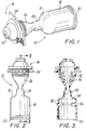
- Fig. 1 is a perspective view illustrating a valve assembly according to the present invention;
- Fig. 2 is a side elevational view illustrating the valve assembly of Figure 1;
- Fig. 3 is a cross-sectional view along line 3-3 of Fig. 2;
- Fig. 4 is a perspective view illustrating an assembly step of the valve assembly of Fig 1;
- Fig. 5 is a perspective partial cut-away view illustrating introduction of fluid into the valve assembly to provide compressive biasing of the valve;
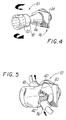
- Fig. 6 is a side elevational partial cut-away view illustrating the valve assembly prior to insertion of a surgical instrument;
- Fig. 7 is a side elevational partial cut-away view illustrating the valve assembly during insertion of a surgical instrument;
- Fig. 8 is a side elevational partial cut-away view illustrating the valve assembly with a surgical instrument fully inserted;
- Fig. 9 is a side elevational partial cut-away view illustrating the valve assembly during removal of a surgical instrument;
- Fig. 10 is a side elevational partial cut-away view illustrating another embodiment of a valve assembly according to the present invention;
- Fig. 11 is a perspective view illustrating another embodiment of a valve assembly according to the present invention;
- Fig. 12 is a side elevational partial cut-away view illustrating the valve assembly with an instrument fully inserted;
- Fig. 13 is a side elevational partial cut-away view illustrating the valve assembly during withdrawal of the instrument;
- Fig. 14 is a side elevational partial cut-away view illustrating another embodiment of the valve assembly according to the present invention;
- Fig. 15 is a side elevational partial cut-away view illustrating the valve assembly showing the clearance afforded an instrument at a distal end of the valve assembly;
- Fig. 16 is a side elevational partial cut-away view illustrating another embodiment of the valve assembly according to the present invention;
- Fig. 17 is a cross-sectional view along line 17-17 of Fig. 8;
- Fig. 18 is an enlarged cross-sectional view as shown in Fig. 17 illustrating a ridge used in accordance with the invention;
- Fig. 19 is a cross-sectional view along line 19-19 of Fig. 18;
- Fig. 20 is an exploded perspective view of a cannula of a trocar assembly illustrating the valve assembly in partial cut-away;
- Fig. 21 is a cross-sectional view of a fully assembled cannula taken along lines 21-21 of Figure 20 illustrating the valve assembly according to the present invention;
- Fig. 22 is a perspective view in partial cut-away of another embodiment of the cannula of Fig. 20 illustrating the valve assembly according to the present invention;
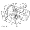
- Fig. 23 is a perspective view in partial cut-away of the cannula of Fig. 22 illustrating another embodiment of the biasing means for the valve assembly;
- Fig. 24 is a perspective view in partial cut-away of the cannula of Fig. 22 illustrating another embodiment of the biasing means for the valve assembly;
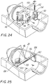
- Fig. 25 is a perspective view in partial cut-away of the cannula of Fig. 22 illustrating another embodiment of the biasing means for the valve assembly;
- Fig. 26 is a top view in partial cut-away of the cannula of Fig. 22 illustrating another embodiment of the biasing means for the valve assembly; and
- Fig. 27 is a top view of a cam used in accordance with the embodiment of Figure 26.
- The present invention contemplates introduction into a patient's body of all types of surgical instruments including, but not limited to clip appliers, lasers, photographic devices, graspers, scissors, tubes, and the like. All of such objects are referred to herein as "instruments".
- Referring now in detail to the drawings, in which like reference numerals identify identical or similar elements, Figures 1-5 illustrate a
valve assembly 10 which includesbody 12 fabricated from a flexibly resilient material, e.g., a thermoplastic elastomeric polymer such as Kraton D, a styrene-butadiene elastomer available from Shell Chemical Co.. Thebody 12 defines a substantially centrallongitudinal aperture 14 which is designed and configured to receive an endoscopic portion of an instrument. Thebody 12 further includes aproximal end portion 16, and adistal end portion 18 which is elongated and substantially cylindrical in shape. Thedistal end portion 18 further includes adistal edge 20 whose significance will be discussed below. Theproximal end portion 16 includes anopening 22, awall plate 24, and an inwardly taperedneck portion 26. Thebody 12 further includes amiddle portion 28 having substantially cylindrical walls. The axial length ofmiddle portion 28 is typically from about 5mm to about 4cm, and preferably about 1.5 to 3cm. - Referring to Figure 3, the
proximal end portion 16 further includes a plurality ofsplines 32 attached to aninner wall 34 and preferably integrally molded as part ofinner wall 34. Alternatively, splines 32 may be insert molded and may include rigid members below the surface ofinner wall 34, e.g., metallic strips or the like. Thesplines 32 extend in a generally longitudinal direction to assist in the insertion of an instrument into theneck portion 26 by reducing friction and drag forces associated therewith. Further, thesplines 32 substantially prevent unwanted contact between the instrument and theinner wall 34 of theneck 26 that may injure or puncture thebody 12. Thedistal portion 18 of thebody 12 includes aninlet port 36 and anoutlet port 38 whose function will be described below. - As shown in Figures 4 and 5, the elongated substantially cylindrical
distal portion 18 is folded onto itself and pulled proximally in the direction of the arrows. Thedistal edge 20 is affixed to theproximal wall plate 24 creating acavity 40 by conventional techniques such as adhesives or heat sealing.Inlet port 36 is provided for injection of agel 42, e.g., silicone, or like substance intocavity 40 whileoutlet port 38 provides a conduit for eliminating air fromcavity 40. Thegel 42fills cavity 40 and provides longitudinal and radial pressure about theaperture 14. Thegel 42 biases themiddle portion 28 ofaperture 14 closed, preventing gases and fluids from escaping through thebody 12 when no instrument is present in thevalve assembly 10. Similarly, thegel 42 biases themiddle portion 28 ofaperture 14 into fluid tight contact when an instrument is present in the aperture by longitudinally and radially providing pressure about theaperture 14.Valve assembly 10 is preferably incorporated into a cannula assembly of a trocar assembly similar to specific embodiments described herein below. -
Aperture 14 is typically dimensioned less than or equal to the diameter of any instrument intended for entry into the proximal end of thebody 12. Preferably,valve assembly 10 is fabricated from a material which is sufficiently flexible and resilient to accommodate and provide a seal about instruments of varying diameters, e.g., diameters of from 3mm to 15mm, and preferable diameters of from 5mm to 12 mm. - Referring to Figures 6-9, a pointed obturator is shown approaching and entering
valve assembly 10; however, any elongated relatively narrow instrument is contemplated. Thevalve assembly 10 accommodates the endoscopic portion of aninstrument 44. Thesplines 32 engage theinstrument 44 and protect the valveinner wall 34 atneck portion 26 while providing for the instrument's smooth entry intoaperture 14. Themiddle portion 28 of thebody portion 12 surrounds the instrument and provides longitudinal and radial pressure which substantially prevents gases or fluids from escaping from the body cavity when the instrument is inserted. Theproximal opening 22 is of such a diameter to sealingly engageinstrument 44 during insertion and withdrawal. - Another embodiment of the
valve assembly 10 is shown in Figure 10. Thevalve assembly 10a is similar to the previous embodiment shown in Figures 1-9, however, the embodiment shown in Figure 10 includes a plurality ofnubs 46, and the splines have been eliminated. Thenubs 46 are positioned in theinner wall 34 of theneck portion 26 and extend outwardly from theinner wall 34. Thenubs 46 engage the instrument during insertion of the instrument and minimize the risk of damage to the elastomeric inner wall, e.g., puncture thereof, by providing an intermediate surface between the instrument and theinner wall 34. The nubs are fabricated of the same elastic material as thevalve assembly 10a and molded integrally with the valve body. Thenubs 46 may also be fabricated of a different suitable flexible material. - Another embodiment of the
valve assembly 10 is shown in Figures 11-13. Thevalve assembly 10b is similar to the previous embodiment shown in Figures 1-9, however, the embodiment shown in Figures 11-13 includes acollar 48 surrounding themiddle portion 28 of thebody 12. Thecollar 48 biases the middle portion of thecentral aperture 14 closed, inhibiting gases and fluids from escaping through thevalve assembly 10b. When an instrument is present in the sealingvalve aperture 14, thecollar 48 forces themiddle portion 28 to substantially surround the instrument and provides longitudinal and radial pressure to discourage any gases or fluids from escaping from the body cavity. - In operation, the
splines 32 engage theinstrument 44 and substantially protect the valveinner wall 34 as in the previous embodiment described above and illustrated in Figures 1-9. In the embodiment shown in Figures 11-13, thecollar 48 which biases themiddle portion 28 of thebody 12 closed accommodates the enteringinstrument 44. Thecollar 48 urges themiddle portion 28 inwardly to substantially surround the instrument and provides longitudinal and radial pressure which substantially discourages gases or fluids from escaping from the body cavity during insertion, utilization and extraction of theinstrument 44 within thevalve assembly 10b.Collar 48 may be constructed of any suitable material having resilient elastic properties, e.g., rubber. - Another embodiment of the
valve assembly 10c is shown in Figure 14-15, and is similar to previous embodiments shown in Figures 10, and 11-13. However, in the embodiment shown in Figures 14-15 thevalve assembly 10c includes adistal end portion 18 which tapers outwardly at anangle 50. Theangle 50 is defined by a longitudinal center line 49 and aline 51 in accord with theinner wall 34 of thebody 12 whenmiddle portion 28 is in its closed configuration, i.e., whencollar 48 has biasedaperture 14 closed. The angle is chosen to substantially discourage contact by an instrument, such as instrument 44a, having ahook 52, as shown in Figure 15 from injuring, e.g., puncturing, or undesirably grabbing theinner wall 34 when the instrument 44a is being removed. Theangle 51 is typically about 20° to 60°, preferably 30°. - Another embodiment of the
valve assembly 10d is shown in Figure 16 and is similar to the previous embodiment shown in Figures 14-15. However, the embodiment shown in Figure 16 has a generally cylindrical shape where the outside diameter of thevalve assembly 10d is substantially constant. A substantiallysolid portion 54 enables thecentral aperture 14 to taper inwardly from the proximal and distal ends 16, 18 as in previous embodiments. Both the proximal and distal endinner wall 34 may includenubs 46, or splines 32 (not shown), andportion 54 may be further biased closed by acollar 48 or a similar biasing means if desired. - Another embodiment of a
valve assembly 10 is illustrated in Figures 18-19 in which themiddle portion 28 includesridges gap 128 which may occur as shown in Fig. 17 between theinstrument 44 and theinner wall 34 after aninstrument 44 of a lesser diameter than theunbiased aperture 14 is inserted. The resilient material of thevalve 10 surrounds theinstrument 44; however, when accommodating aninstrument 44 smaller in diameter than theunbiased aperture 14 at themiddle portion 28, thegap 128 forms at least at one side adjacent to the instrument between the instrument and theinner wall 34 as shown in Figure 17. A properly placed ridge or set ofridges inner wall 34 substantially fills thegap 128 as shown in Fig. 18. - A plurality of ridges or sets of ridges may be used as in Figure 19 so that the
gap 128 resulting from using differentsized instruments 44, all of which are smaller in diameter than the unbiasedcentral aperture 14, can be eliminated by the properly positionedridges - More specifically, the
ridges 126 may, for example, fill agap 128 when an 8mm diameter instrument is inserted through thevalve assembly 10. Similarly, theridges 127 may, for example, fill agap 128 when a 5mm diameter instrument is inserted through thevalve assembly 10. Typically, the ridges or complementary pairs of ridges are axially spaced alongmiddle portion 28. - Preferably, the
valve assembly 10 is incorporated in acannula assembly 56 of a trocar assembly as best seen in Fig. 20. Thevalve assembly 10 is similar to the previous embodiment shown in Figures 14-15. Thecannula assembly 56 includes a valve housing having an upperhousing half section 60 and a lowerhousing half section 62, shown separated in Figure 20 for convenience of illustration. Thehousing half sections - The valve or cannula housing includes
neck 64 at a distal end having anaperture 65 dimensioned for reception of an appropriate tube such ascannula 66. Thecannula 66 is fabricated of a rigid material such as a plastic, fiberglass or metal. The proximal end of thevalve housing 68 includes apartition 72 for stabilizing thevalve assembly 10. - The lower
housing half section 62 is shown with the upperhousing half section 60 removed, so as to illustrate thenovel valve assembly 10 of the present invention. Thevalve assembly 10 is shown partially cut away and in cross section for illustration purposes. Dualreciprocating securing members 74, as seen in Figure 21, extends across themiddle portion 28 of thebody 12 as shown. Thepartition 72 holds the proximal end of thevalve assembly 10 in position atplate 24 while theear 76 affixed tomiddle portion 28 is connected to acorresponding clamp blade 80 for stabilizing the middle anddistal end portions partition 72 is constructed of the same relatively rigid plastic material as the valve housing such as polycarbonate, polyethylene or the like. - The
valve assembly 10 includesclamp blades 80 which are connected to the inner surface of the lowerhousing half section 62 and the upperhousing half section 60. Eachclamp blade 80 is biased in a direction toward the other by atorsion spring 85 having one leg in engagement with the adjacent housing wall and the other leg in engagement with apivotal arm 86 pivotally mounted at pivot pins 88. Eachpivot arm 86 extends as shown, into the path ofpins bores 94. - The inner end of each
pin pivotal arm 86 such that manually depressing theslidable pins pivot arms 86 to pivotally rotate away from each other. This motion causes theclamp blades 80 to separate allowing themiddle portion 28 of thevalve assembly 10 to open. When thepins middle portion 28 collapses to the configuration shown in Figure 21 under action of theclamp blades 80 and the springs which provide a substantially gas tight seal between theproximal end 16 of thevalve assembly 10 and thedistal end 18. The sealing effect of theblades 80 on thevalve assembly 10 is of sufficient gas tight character that pressurized gases used to insufflate a body cavity will not pass through thevalve 10 when theinstrument 44 is removed. - The
pins blades 80 to permit entry of the instrument throughvalve assembly 10, through thecannula 56 and into the body cavity. At this point, the tight contact between theinstrument 44 and theinner wall 34 has sealed the inner body cavity from the outside atmosphere. This seal is provided by the resilient property of the stretched elastomeric material atmiddle portion 28 surrounding theaperture 14. Manipulation of theinstrument 44 in any direction will not affect the seal, since the elastomeric material defining theaperture 14 will conform to the movements of the instrument and assume a shape necessary to maintain contact. - The
aperture 14 is preferably dimensioned having a diameter between 3 and 15mm to accommodate instruments such as clip appliers, laser tubes, photographic instruments, tubes or the like. However, depending upon need or application this dimensional range may be varied to accommodate any particular instrument. - Another embodiment of the
cannula assembly 56 andvalve assembly 10 is shown in Figure 22, which is similar to the previous embodiment shown in Figure 21. However in the embodiment shown in Figure 22 the valve assembly includes generallycylindrical pinching members 96. Ashaft 97 extends longitudinally through eachmember 96 and extends into agroove 98 in aplate 100 connected to the inner surface of the lowerhousing half section 62. Theshaft 97 rides freely in the groove and is supported by asupport bar 104 attached to theplate 100. Aspring 106 positioned in thegroove 98 biases theshaft 97, and thusmember 96 to the position shown at one end of thegroove 98.Member 96 biases themiddle portion 28 of thevalve assembly 10 in the closed position substantially preventing gases from entering or exiting. Actuation levers 90, 92, positioned in this embodiment perpendicular tolevers members 96 to openvalve assembly 10. - In operation, upon insertion of an instrument into the proximal end of the
valve housing 68 and the proximal end of thevalve assembly 10, thenubs 46 engage the instrument providing substantial protection to theinner wall 34.Members 96 are moved in response to actuation oflevers shafts 97 respond by moving in theircorresponding grooves 98.Middle portion 28 ofvalve assembly 10 provides longitudinal and radial pressure in conjunction withmembers 96 to the instrument, thus providing and maintaining a substantial gas tight seal. - Another embodiment of the valve assembly and cannula assembly is shown in Figure 23 and is similar to the previous embodiment shown in Figure 22. However, in the embodiment shown in Figure 23 the valve assembly includes a
resilient member 108 biased in a generally "U" shaped configuration which replaces springs 106. Theresilient member 108 is attached to the bottom portion of theshafts 97 andbiases shafts 97, and therebymembers 96, in the closed position. The embodiment shown in Figure 23 operates similar to the embodiment shown in Figure 22. - Another embodiment of the
cannula assembly 56 and thevalve assembly 10 is shown in Figure 24, and is similar to previous embodiments shown in Figures 22 and 23, except for the provision ofparallel bars 110 which are positioned in the lower andupper half sections cannula housing 56 substantially about themiddle portion 28 of thevalve assembly 10. Thebars 110 are biased towards each other bysprings 112 attached at their distal ends and aligned ingrooves 114. In operation, when an instrument is inserted into thecannula assembly 56 and into thevalve assembly 10 thebiased bars 110 move in thegrooves 114 against the biasing of the springs and maintain a gas tight seal about the instrument. - Another similar embodiment of the
cannula assembly 56 and thevalve assembly 10 is shown in Figure 25. In this embodiment, thevalve assembly 10 includes a resilient onepiece bar 116 having an opening in amiddle segment 118 to accommodate themiddle portion 28 ofvalve assembly 10. The opposite distal ends 120 of theresilient bar 116 are connected to theside wall receptacles 124. Of course, bar 116 may be constructed of two members overlapping each other. - When an instrument is inserted into the
cannula assembly 56 and into thevalve assembly 10 theresilient bar 116 accommodates the instrument, while assistingvalve assembly 10 in providing longitudinal and radial pressure about the instrument to maintain a fluid tight seal. - When the
valve assembly 10 is used as part of acannula assembly 56 as in the present embodiment of Figures 20-25, an obturator of the trocar assembly is fitted within the cannula assembly and used to insert the cannula into a body cavity by first penetrating the cavity wall. Thereafter, the obturator is removed, permitting insertion of instruments into the patient's body through the cannula to perform the desired procedure. Thus, the significance of providing control to the surgeon over an assuredly sealed cannula valve assembly cannot be over-emphasized. For laparoscopic procedures the valve assembly will prevent leakage of gases to maintain insufflation of the cavity during the surgical procedures. - Another embodiment of the
valve assembly 10 positioned in acannula assembly 56 is shown in Figures 26 and 27 and is similar to the previous embodiments shown in Figures 21-25. However, in the embodiment shown in Figures 26 and 27 thevalve assembly 10 preferably includes a pair ofpivotable cams 130 positioned in thelower half section 62 of thecannula housing 56. Thecams 130 act as biasing means for biasing themiddle portion 28 of thevalve assembly 10 closed prior to instrument insertion into thevalve assembly 10, and for biasingmiddle portion 28 against the outer surface of an inserted instrument. - Each
cam 130 includes apivot point 132 at a proximal end and anattachment portion 134 for coupling with anactuating spring 136. Thecams 130 further include contact faces 138 and stop surfaces 140. Thecams 130 are positioned on opposite sides of themiddle portion 28 and are biased towards one another by theactuation spring 136, thus, thecams 130 work in concert to bias closed themiddle portion 28 of thevalve assembly 10 between them. - In operation, prior to instrument insertion in the
valve assembly 10, the actuating spring biases thecams 130 towards one another thereby biasing closed themiddle portion 28 of thevalve assembly 10 and providing a substantially gas tight seal. After instrument insertion into thevalve assembly 10, thecams 130 pivot at their proximal pivot points 132 and rotate distally against the biasing action of theactuation spring 136 assuming the position shown by the dotted lines in Fig. 26. Thecams 130 encourage themiddle portion 28 of thevalve assembly 10 to engage the outer surface of the inserted instrument and, thereby, thevalve assembly 10 provides and maintains a substantially gas tight seal. Lastly, the stop surfaces 140 contact aside wall 142 of thelower half section 62 of thecannula housing 56 when thecams 130 are fully rotated. - The valve assembly described above in the preferred embodiments and illustrated in the accompanying drawings is preferably capable of accommodating instruments varying in diameter of from 3mm to 15mm, and preferably for diameters of from 5mm to 12mm. When inserting the instrument into the valve assembly as described in the above embodiments and illustrated in the accompanying drawings, the insertion force, i.e., the axial force asserted against the instrument to pass the instrument into and through the valve assembly is preferably kept to a minimum. For example, preferable insertion forces of approximately no more than 5 pounds are desirable for instruments having approximate diameters of more than 9mm. Insertion forces of approximately no more than 4 pounds are desirable for instruments having approximate diameters of between 5mm and 8mm.
- Moreover, preferable insertion forces of approximately 7 pounds are desirable for instruments having approximate diameters of 9mm to 15mm. Insertion forces of approximately no more than 6 pounds are desirable for instruments having approximate diameters of between 10mm and 12mm.
Claims (37)
- A valve assembly for sealing an incision in a patient's body and adapted for introduction of a surgical instrument into the patient's body comprising:
a valve body formed of a flexibly resilient material and defining an aperture for reception of the instrument, said aperture being configured and dimensioned such that insertion of the instrument into said valve body will cause said valve body to resiliently engage an outer surface of the instrument in a substantially gas tight manner; and
means to bias at least a portion of said valve body to a configuration whereby said aperture is closed to form a substantially gas tight seal prior to inserting the instrument therethrough. - A valve assembly according to claim 1, wherein said biasing means comprises a gel.
- A valve assembly according to claim 1 or 2, wherein said valve body is cylindrically shaped and includes an outer diameter which is substantially uniform from a proximal end to a distal end.
- A valve assembly according to claim 1, 2 or 3 wherein said valve body is adapted to engage an outer surface of surgical instruments having a multiplicity of diameters in a substantially gas tight manner.
- A valve assembly according to any one of the preceding claims, wherein said instrument has a diameter in a range of from 3mm to 15mm.
- A valve assembly according to any one of the preceding claims with an inner wall which tapers inwardly.
- A valve assembly according to claim 6, wherein said inner wall tapers to a middle portion having lesser diameter than said inner wall at said distal and proximal ends.
- A valve assembly according to claim 6 or 7, wherein said aperture has a generally frustoconical, inwardly tapered cross-section from a proximal end to an intermediate portion.
- A valve assembly according to claim 6, 7 or 8 wherein said aperture is generally tapered inwardly in a generally frustoconical cross-section from said distal end of said valve body to said intermediate portion.
- A valve assembly according to claim 6, 7 or 8 wherein said aperture has a generally cylindrical cross-section from said intermediate portion to a distal end.
- A valve assembly according to any one of the preceding claims in which the valve body has a cavity between an inner wall and an outer wall of the body, the inner wall defining an aperture through the valve body.
- A valve assembly according to claim 11, wherein said biasing means comprises a fluid substantially filling said cavity.
- A valve assembly according to any one of the preceding claims, wherein said biasing means comprising a biasing member located radially outside the valve body.
- A valve assembly according to claim 13, wherein said biasing means comprises a circumferential collar about a portion of said valve body.
- A valve assembly according to any one of the preceding claims, including means for guiding said instrument through said aperture.
- A valve assembly according to claim 15, wherein said guiding means comprises a plurality of projecting members positioned on an inner wall of said valve body radially extending into said aperture to engage an instrument inserted into said aperture to substantially prevent contact between said instrument and said inner wall of said valve body.
- A valve assembly according to claim 16, wherein the projections are ribs or splines.
- A valve assembly according to claim 17, wherein said rib members extend longitudinally from said proximal end of said valve body.
- A valve assembly according to claim 16, 17 or 18 wherein the projecting members are adjacent at least a proximal end of the valve body.
- A valve assembly according to any one of the preceding claims, further comprising:
at least one ridge member positionable on an inner surface of said resilient material defining said aperture, said ridge member being positioned, configured, and dimensioned to substantially fill a gap formed between said resilient material and said instrument when said instrument is passed through said aperture. - A valve assembly according to claim 20, wherein said valve body includes a middle portion which is biased closed by said means for biasing and said ridge member is positionable within a neck portion.
- A valve assembly according to claim 20 or 21, wherein a plurality of said ridge members cooperate to substantially fill said gap.
- A valve assembly according to claim 20, 21 or 22, wherein said aperture includes a plurality of said ridge members being positioned about said inner surface at predetermined locations such that said ridge members substantially fill the gaps which occur respectively when surgical instruments having a multiplicity of diameters are inserted through said aperture one at a time.
- A valve assembly according to claim 22 or 23, wherein said plurality of ridge members includes at least a first ridge adapted for use when said instrument inserted has a first diameter and at least a second ridge axially offset from said first ridge and for use when said instrument inserted has a second diameter different from said first diameter.
- A valve assembly according to any one of claims 20 to 24, wherein said ridge member extends longitudinally along a portion of said inner surface of said resilient material defining said aperture and corresponds with said portion of said valve body associated with said means for biasing.
- A valve assembly according to any one of the preceding claims, wherein said biasing means comprises manually actuated means to selectively open and close said aperture to permit passage of the instrument therethrough.
- A valve assembly according to any one of the preceding claims, wherein said biasing means is pivotable.
- A valve assembly according to claim 27, wherein said pivotable biasing means includes a spring actuation for biasing said valve body.
- A valve assembly according to claim 27 or 28, wherein said biasing means includes at least one pivotable cam.
- A valve assembly according to claim 29, wherein said pivotable cam biases said valve body while allowing an endoscopic portion of said instrument to pass through said valve body such that said valve body engages the surface of said instrument to provide a substantially fluid tight seal after insertion of said instrument into said valve body.
- A valve assembly according to any one of the preceding claims, wherein said biasing means includes at least a pair of cams positioned opposite each other and having said body portion of said valve assembly therebetween, said cams working in concert to bias said body portion closed.
- A valve assembly for sealing an incision in a patient's body and adapted for introduction of surgical instruments into the patient's body comprising:
a cylindrical valve body having an inner wall and an outer wall defining a cavity therebetween, said inner wall forming an aperture passing through said valve body;
means for facilitating passage of an instrument through said aperture. - A valve assembly for sealing an incision in a patient's body and adapted for introduction of surgical instruments into the patient's body comprising:
a valve body formed of a flexibly resilient material and having a distal end, a proximal end and a middle portion therebetween, said valve body defining an aperture therethrough; and
means for biasing at least a portion of said valve body to a configuration whereby said aperture is closed in said middle portion to form a substantially gas tight seal prior to inserting the instrument therethrough. - A valve assembly for sealing an incision in a patient's body and adapted for introduction of a surgical instrument into the patient's body comprising:
a valve body formed of a flexibly resilient material and defining an aperture for reception of the instrument, said aperture being configured and dimensioned such that insertion of the instrument into said valve body will cause the valve body to resiliently engage the instrument in a substantially gas tight manner, said aperture having a substantially constant diameter at least at an intermediate portion of said valve body;
means to bias said valve body to a configuration whereby said aperture is closed to form a gas tight seal prior to inserting the instrument therethrough; and
means to permit said biasing means to be selectively opened or closed so as to allow passage of the instrument through said aperture. - A cannula housing including a valve assembly as claimed in any one of the preceding claims.
- A cannula subassembly including a cannula and a cannula housing adapted for the introduction of surgical instruments into a patient's body comprising:
a valve body positioned within said cannula housing having distal end and a proximal end, said valve body formed of a flexibly resilient material and defining an aperture for reception of the instrument, said aperture having a lesser diameter at a portion intermediate said ends than at said distal and proximal ends, said aperture being configured and dimensioned such that insertion of the instrument into said aperture will cause the valve body to resiliently engage the outer surface of the instrument in a substantially gas tight manner; and
a pair of plate members positioned to engage said intermediate portion of said valve body, said plate members being biased toward each other to close said aperture to form a gas tight seal prior to positioning the instrument therein. - A cannula subassembly according to claim 36, further comprising manually operable means adapted to separate said plate members in a manner to selectively manually open and close said aperture to permit passage of the instrument therethrough.
Priority Applications (1)
| Application Number | Priority Date | Filing Date | Title |
|---|---|---|---|
| EP96109406A EP0733344B1 (en) | 1992-04-24 | 1993-04-23 | Valve assembly for introducing instruments into body cavities |
Applications Claiming Priority (2)
| Application Number | Priority Date | Filing Date | Title |
|---|---|---|---|
| US87429192A | 1992-04-24 | 1992-04-24 | |
| US874291 | 1997-06-13 |
Related Child Applications (2)
| Application Number | Title | Priority Date | Filing Date |
|---|---|---|---|
| EP96109406A Division EP0733344B1 (en) | 1992-04-24 | 1993-04-23 | Valve assembly for introducing instruments into body cavities |
| EP96109406.7 Division-Into | 1996-06-12 |
Publications (3)
| Publication Number | Publication Date |
|---|---|
| EP0567141A2 true EP0567141A2 (en) | 1993-10-27 |
| EP0567141A3 EP0567141A3 (en) | 1994-01-12 |
| EP0567141B1 EP0567141B1 (en) | 1997-09-03 |
Family
ID=25363422
Family Applications (2)
| Application Number | Title | Priority Date | Filing Date |
|---|---|---|---|
| EP96109406A Expired - Lifetime EP0733344B1 (en) | 1992-04-24 | 1993-04-23 | Valve assembly for introducing instruments into body cavities |
| EP93106631A Expired - Lifetime EP0567141B1 (en) | 1992-04-24 | 1993-04-23 | Valve assembly for introducing instruments into body cavities |
Family Applications Before (1)
| Application Number | Title | Priority Date | Filing Date |
|---|---|---|---|
| EP96109406A Expired - Lifetime EP0733344B1 (en) | 1992-04-24 | 1993-04-23 | Valve assembly for introducing instruments into body cavities |
Country Status (5)
| Country | Link |
|---|---|
| US (3) | US5360417A (en) |
| EP (2) | EP0733344B1 (en) |
| AU (1) | AU3712793A (en) |
| CA (1) | CA2093748C (en) |
| DE (2) | DE69313504T2 (en) |
Cited By (16)
| Publication number | Priority date | Publication date | Assignee | Title |
|---|---|---|---|---|
| EP0674879A1 (en) * | 1994-03-31 | 1995-10-04 | YOON, InBae | Endoscopic portal |
| EP0696459A1 (en) | 1994-08-08 | 1996-02-14 | United States Surgical Corporation | Valve system for cannula assembly |
| WO1996013301A2 (en) * | 1994-10-27 | 1996-05-09 | Abbott Laboratories | Valved intravenous fluid line infusion device |
| EP0716862A1 (en) * | 1994-12-15 | 1996-06-19 | United States Surgical Corporation | Seal assembly for accomodating introduction of surgical intruments |
| US5599305A (en) * | 1994-10-24 | 1997-02-04 | Cardiovascular Concepts, Inc. | Large-diameter introducer sheath having hemostasis valve and removable steering mechanism |
| EP0771574A1 (en) * | 1995-11-01 | 1997-05-07 | Cordis Corporation | Gasket for catheter hemostasis valve |
| US5820600A (en) * | 1996-05-14 | 1998-10-13 | Innerdyne, Inc. | Adjustable introducer valve |
| NL1007997C2 (en) * | 1998-01-09 | 1999-07-12 | Cordis Europ | Device for inserting an elongated medical device. |
| EP1032454A1 (en) * | 1996-06-12 | 2000-09-06 | Biolink Corporation | Device for subcutaneous accessibility |
| EP1679043A1 (en) * | 2005-01-06 | 2006-07-12 | Tyco Healthcare Group Lp | Surgical seal for use in a surgical access apparatus |
| EP1852074A2 (en) | 2006-05-03 | 2007-11-07 | Karl Storz GmbH & Co. KG | Seal for a trocar sheath and such a trocar sheath |
| DE102007040358A1 (en) | 2007-08-27 | 2009-03-05 | Technische Universität München | Trocar tube, trocar, obturator or rectoscope for transluminal endoscopic surgery over natural orifices |
| WO2009058308A1 (en) | 2007-10-30 | 2009-05-07 | William Cook Europe Aps | Haemostatic valve |
| US8377089B2 (en) | 2004-03-22 | 2013-02-19 | Smith & Nephew, Inc. | Medical cannula assembly |
| DE202012012578U1 (en) | 2012-11-20 | 2013-09-16 | Trokasure Gbr (Vertretungsberechtigter Gesellschafter: Dr. Med. Gerold Kreuz, 02997 Wittichenau) | trocar |
| WO2014079807A2 (en) | 2012-11-20 | 2014-05-30 | Trokasure Gbr | Trocar device and use thereof |
Families Citing this family (207)
| Publication number | Priority date | Publication date | Assignee | Title |
|---|---|---|---|---|
| US5395342A (en) | 1990-07-26 | 1995-03-07 | Yoon; Inbae | Endoscopic portal |
| CA2093748C (en) * | 1992-04-24 | 1996-11-12 | Roy D. Gravener | Valve assembly for introducing instruments into body cavities |
| US5720734A (en) * | 1994-02-28 | 1998-02-24 | Wilson-Cook Medical, Inc. | Gastrostomy feeding ports |
| AU4763296A (en) * | 1995-02-03 | 1996-08-21 | Inbae Yoon | Cannula with distal end valve |
| US5964781A (en) * | 1995-05-19 | 1999-10-12 | General Surgical Innovations, Inc. | Skin seal with inflatable membrane |
| US5634911A (en) * | 1995-05-19 | 1997-06-03 | General Surgical Innovations, Inc. | Screw-type skin seal with inflatable membrane |
| US5634937A (en) | 1995-05-19 | 1997-06-03 | General Surgical Innovations, Inc. | Skin seal with inflatable membrane |
| US5997515A (en) | 1995-05-19 | 1999-12-07 | General Surgical Innovations, Inc. | Screw-type skin seal with inflatable membrane |
| US5584850A (en) * | 1995-05-25 | 1996-12-17 | Applied Medical Resources Corporation | Trocar having an anti-inversion seal |
| US5782817A (en) * | 1995-11-06 | 1998-07-21 | Cordis Corporation | Catheter introducer having toroidal valve |
| US5814026A (en) * | 1996-03-19 | 1998-09-29 | Yoon; Inbae | Endoscopic portal having a universal seal and methods for introducing instruments therethrough |
| US5788676A (en) * | 1996-03-25 | 1998-08-04 | Yoon; Inbae | Endoscopic portal having multiple universal seals and method of introducing instruments therethrough |
| US5882345A (en) * | 1996-05-22 | 1999-03-16 | Yoon; Inbae | Expandable endoscopic portal |
| JP2957134B2 (en) * | 1996-10-08 | 1999-10-04 | 株式会社八光電機製作所 | Valve and valved trocar mantle |
| US5895376A (en) | 1996-10-23 | 1999-04-20 | Mayo Foundation For Medical Education And Research | Hemostasis valve, system and assembly |
| US6276661B1 (en) * | 1996-11-06 | 2001-08-21 | Medtronic, Inc. | Pressure actuated introducer valve |
| US7056316B1 (en) | 1997-01-21 | 2006-06-06 | Vasca, Inc. | Valve port and method for vascular access |
| US5906595A (en) * | 1997-04-25 | 1999-05-25 | Ethicon Endo-Surgery, Inc. | Trocar having protector with flexible end and improved seal assembly |
| CA2289101C (en) * | 1997-05-02 | 2006-07-18 | David C. Racenet | Trocar seal system |
| US5779697A (en) * | 1997-05-28 | 1998-07-14 | Linvatec Corporation | Arthroscopic cannula with fluid seals |
| EP1015049B1 (en) * | 1997-05-28 | 2004-08-18 | United States Surgical Corporation | Trocar seal system |
| US6589167B1 (en) | 1997-10-08 | 2003-07-08 | Hakko Electric Machine Works Co., Ltd. | Valve and valved trocar jacket tube |
| WO1999024097A1 (en) * | 1997-11-12 | 1999-05-20 | Stereotaxis, Inc. | Intracranial bolt and method of placing and using an intracranial bolt to position a medical device |
| US6511512B2 (en) * | 1998-04-10 | 2003-01-28 | Ossur Hf | Active shock module prosthesis |
| USD426635S (en) * | 1998-08-18 | 2000-06-13 | Genicon, Lc | Combination trocar, cannula, and valve |
| EP1229902A4 (en) * | 1999-11-01 | 2003-01-02 | Vasca Inc | Valve port and method for vascular access |
| USD449887S1 (en) | 2000-01-26 | 2001-10-30 | Genicon Lc | Combined obturator, cannula and valve assembly |
| US7153319B1 (en) | 2000-01-26 | 2006-12-26 | Genico, Inc. | Trocar system having shielded trocar |
| USD443360S1 (en) | 2000-03-22 | 2001-06-05 | Dexterity Surgical Inc. | Distal end of obturator for a trocar |
| US6699221B2 (en) * | 2000-06-15 | 2004-03-02 | Vincent L. Vaillancourt | Bloodless catheter |
| DE60135765D1 (en) * | 2000-10-13 | 2008-10-23 | Tyco Healthcare | VALVE ASSEMBLY WITH A STRUCTURE FOR DIAMETER REDUCTION OF A TROCAR |
| US20060020281A1 (en) | 2000-10-13 | 2006-01-26 | Smith Robert C | Valve assembly including diameter reduction structure for trocar |
| WO2002034108A2 (en) | 2000-10-19 | 2002-05-02 | Applied Medical Resources Corporation | Surgical access apparatus and method |
| US6629530B2 (en) * | 2000-12-22 | 2003-10-07 | Kimberly-Clark Worldwide, Inc. | Single-element sealing valve for a respiratory support system |
| DE10121356B4 (en) * | 2001-05-02 | 2005-02-24 | Karl Storz Gmbh & Co. Kg | Valve arrangement for surgical instruments and valve basket for receiving the valve arrangement |
| WO2003015848A1 (en) | 2001-08-14 | 2003-02-27 | Applied Medical Resources Corporation | Access sealing apparatus and method |
| US6659937B2 (en) * | 2001-10-11 | 2003-12-09 | M. Sheldon Polsky | Continent bladder access device |
| US6958037B2 (en) | 2001-10-20 | 2005-10-25 | Applied Medical Resources Corporation | Wound retraction apparatus and method |
| US7235062B2 (en) * | 2002-01-24 | 2007-06-26 | Applied Medical Resources Corporation | Surgical access device with floating gel seal |
| AU2003216359A1 (en) * | 2002-02-19 | 2003-09-09 | Medamicus, Inc. | Composite stasis valve |
| EP2340792B1 (en) | 2002-06-05 | 2012-05-09 | Applied Medical Resources Corporation | Wound retractor |
| US20040172008A1 (en) * | 2002-11-19 | 2004-09-02 | Gmp/Cardiac Care, Inc. | Hemostasis valve and method of using a hemostasis valve |
| US7390317B2 (en) * | 2002-12-02 | 2008-06-24 | Applied Medical Resources Corporation | Universal access seal |
| US20050020884A1 (en) | 2003-02-25 | 2005-01-27 | Hart Charles C. | Surgical access system |
| US9486241B2 (en) | 2003-03-21 | 2016-11-08 | Ethicon Endo-Surgery, Llc | Trocar seal assembly |
| US8147457B2 (en) * | 2003-03-21 | 2012-04-03 | Ethicon Endo-Surgery, Inc. | Conical trocar seal |
| US20050059934A1 (en) | 2003-04-25 | 2005-03-17 | Thomas Wenchell | Surgical access apparatus |
| CA2522766C (en) * | 2003-04-25 | 2011-07-05 | Tyco Healthcare Group Lp | Surgical hand access apparatus |
| WO2004112865A2 (en) * | 2003-06-18 | 2004-12-29 | Pressure Products Medical Supplies Inc. | A method and apparatus with a splittable hemostatic valve with a variable aperture |
| CA2533204A1 (en) | 2003-08-06 | 2005-02-17 | Applied Medical Resources Corporation | Surgical device with tack-free gel and method of manufacture |
| US7241276B2 (en) * | 2003-08-06 | 2007-07-10 | Trivascular, Inc. | Passive hemostatic sheath valve |
| US7163510B2 (en) | 2003-09-17 | 2007-01-16 | Applied Medical Resources Corporation | Surgical instrument access device |
| US20050070850A1 (en) * | 2003-09-30 | 2005-03-31 | Albrecht Thomas E. | Low-profile, recessed stop-cock valve for trocar assembly |
| US20050070947A1 (en) * | 2003-09-30 | 2005-03-31 | Franer Paul T. | Rotational latching system for a trocar |
| US7785294B2 (en) * | 2003-09-30 | 2010-08-31 | Ethicon Endo-Surgery, Inc. | Woven protector for trocar seal assembly |
| US8029475B2 (en) * | 2003-09-30 | 2011-10-04 | Ethicon Endo-Surgery, Inc. | Reinforced seal assembly |
| US8012128B2 (en) * | 2003-09-30 | 2011-09-06 | Ethicon Endo-Surgery Inc. | Button latching system for a trocar |
| US7597701B2 (en) * | 2003-09-30 | 2009-10-06 | Ethican Endo-Surgery, Inc. | Instrument lock assembly for trocar |
| US8206411B2 (en) * | 2003-09-30 | 2012-06-26 | Ethicon Endo-Surgery, Inc. | Trocar housing/stop-cock assembly |
| US8034032B2 (en) * | 2003-09-30 | 2011-10-11 | Ethicon Endo-Surgery, Inc. | Multi-angled duckbill seal assembly |
| DE10346612A1 (en) * | 2003-10-08 | 2005-05-19 | Robert Bosch Gmbh | Method for forecasting a temporal development of a system size |
| US8262622B2 (en) * | 2003-10-28 | 2012-09-11 | Applied Medical Resources Corporation | Surgical gel seal |
| US7842013B2 (en) | 2004-01-23 | 2010-11-30 | Genico, Inc. | Trocar and cannula assembly having conical valve and related methods |
| US8083728B2 (en) | 2004-03-18 | 2011-12-27 | C. R. Bard, Inc. | Multifunction adaptor for an open-ended catheter |
| US7578803B2 (en) * | 2004-03-18 | 2009-08-25 | C. R. Bard, Inc. | Multifunction adaptor for an open-ended catheter |
| US7594911B2 (en) | 2004-03-18 | 2009-09-29 | C. R. Bard, Inc. | Connector system for a proximally trimmable catheter |
| US7854731B2 (en) * | 2004-03-18 | 2010-12-21 | C. R. Bard, Inc. | Valved catheter |
| US7594910B2 (en) | 2004-03-18 | 2009-09-29 | C. R. Bard, Inc. | Catheter connector |
| US7686825B2 (en) | 2004-03-25 | 2010-03-30 | Hauser David L | Vascular filter device |
| US7377915B2 (en) | 2004-04-01 | 2008-05-27 | C. R. Bard, Inc. | Catheter connector system |
| US7582070B2 (en) * | 2004-04-09 | 2009-09-01 | Cook Vascular Incorporated | Modular hemostatic valve |
| US20070066988A1 (en) * | 2005-09-22 | 2007-03-22 | Keshava Datta | Trocar obturator with cutting edges |
| FR2872696B1 (en) * | 2004-07-07 | 2007-09-28 | Perouse Soc Par Actions Simpli | INTRODUCER FOR ENDOLUMINAL INTERVENTION |
| WO2006020673A1 (en) * | 2004-08-11 | 2006-02-23 | Steven Smith | Self-occluding sheath |
| US8241251B2 (en) | 2004-08-25 | 2012-08-14 | Tyco Healthcare Group Lp | Gel seal for a surgical trocar apparatus |
| DE102004045586B3 (en) | 2004-09-17 | 2006-05-04 | Karl Storz Gmbh & Co. Kg | Valve for medical instruments |
| WO2006034436A2 (en) | 2004-09-21 | 2006-03-30 | Stout Medical Group, L.P. | Expandable support device and method of use |
| US20060071432A1 (en) * | 2004-09-29 | 2006-04-06 | Staudner Rupert A | Seal for trocar |
| US7163525B2 (en) * | 2004-12-17 | 2007-01-16 | Ethicon Endo-Surgery, Inc. | Duckbill seal protector |
| US7371227B2 (en) * | 2004-12-17 | 2008-05-13 | Ethicon Endo-Surgery, Inc. | Trocar seal assembly |
| US7481795B2 (en) * | 2004-12-17 | 2009-01-27 | Ethicon Endo-Surgery, Inc. | Circumferential trocar seal assembly |
| US20060229655A1 (en) * | 2005-03-30 | 2006-10-12 | Ethicon Endo-Surgery, Inc. | Two part bullet assembly |
| WO2006113800A2 (en) * | 2005-04-20 | 2006-10-26 | Stout Medical Group, Llc | Self-sealing surgical access port |
| US7591802B2 (en) * | 2005-04-29 | 2009-09-22 | Applied Medical Resources Corporation | Seal housing having anti-inversion features |
| US7875019B2 (en) | 2005-06-20 | 2011-01-25 | C. R. Bard, Inc. | Connection system for multi-lumen catheter |
| EP2000099A3 (en) | 2005-10-14 | 2009-07-29 | Applied Medical Resources Corporation | Surgical Access Port |
| JP5132565B2 (en) | 2005-10-14 | 2013-01-30 | アプライド メディカル リソーシーズ コーポレイション | Method for manufacturing hand access instrument for laparoscopy |
| US20070112368A1 (en) * | 2005-11-17 | 2007-05-17 | Applied Medical Resources Corporation | Method for using a trocar with inflatable seal for transstomal endoscopic procedures |
| US8690831B2 (en) | 2008-04-25 | 2014-04-08 | Ethicon Endo-Surgery, Inc. | Gas jet fluid removal in a trocar |
| US8579807B2 (en) | 2008-04-28 | 2013-11-12 | Ethicon Endo-Surgery, Inc. | Absorbing fluids in a surgical access device |
| CN1907513A (en) * | 2006-07-31 | 2007-02-07 | 周泰立 | One-way valve for puncture outfit |
| JP4994775B2 (en) | 2006-10-12 | 2012-08-08 | 日本コヴィディエン株式会社 | Needle point protector |
| US20080097332A1 (en) * | 2006-10-18 | 2008-04-24 | Stout Medical Group L.P. | Surgical access port |
| US20080171988A1 (en) * | 2007-01-17 | 2008-07-17 | Erblan Surgical, Inc. | Double-cone sphincter introducer assembly and integrated valve assembly |
| US8226552B2 (en) | 2007-05-11 | 2012-07-24 | Applied Medical Resources Corporation | Surgical retractor |
| EP2146643A4 (en) | 2007-05-11 | 2012-05-30 | Applied Med Resources | Surgical retractor with gel pad |
| ES2373072T3 (en) * | 2007-05-22 | 2012-01-31 | Tyco Healthcare Group Lp | ACCESS SET WITH TRIQUITA BOARD. |
| US7762990B2 (en) * | 2007-05-24 | 2010-07-27 | Tyco Healthcare Group Lp | Surgical access apparatus with centering mechanism |
| CA2631825A1 (en) * | 2007-05-24 | 2008-11-24 | Tyco Healthcare Group Lp | Surgical portal apparatus with armature assembly |
| US8100929B2 (en) * | 2007-06-29 | 2012-01-24 | Ethicon Endo-Surgery, Inc. | Duckbill seal with fluid drainage feature |
| US7918826B2 (en) | 2007-09-14 | 2011-04-05 | Ethicon Endo-Surgery, Inc. | Trocar assembly |
| US8357123B2 (en) | 2007-09-17 | 2013-01-22 | Covidien Lp | Surgical portal with gel and fabric seal assembly |
| US20090076465A1 (en) * | 2007-09-17 | 2009-03-19 | Tyco Healthcare Group Lp | Composite seal and method for manufacturing |
| US20090093682A1 (en) * | 2007-10-05 | 2009-04-09 | Tyco Healthcare Group Lp | Surgical portal with foam and fabric composite seal assembly |
| BRPI0817421A2 (en) | 2007-10-05 | 2015-06-16 | Tyco Healthcare | Sealing fastener for use in surgical procedures |
| US7976501B2 (en) | 2007-12-07 | 2011-07-12 | Ethicon Endo-Surgery, Inc. | Trocar seal with reduced contact area |
| EP2237815B1 (en) | 2008-01-22 | 2020-08-19 | Applied Medical Resources Corporation | Surgical instrument access device |
| US8277410B2 (en) * | 2008-03-13 | 2012-10-02 | Boston Scientific Scimed, Inc. | Methods and apparatus for inhibiting introduction of air into the vasculature during a percutaneous procedure |
| AU2009223316B2 (en) | 2008-03-14 | 2014-05-29 | Applied Medical Resources Corporation | Instrument seal |
| USD700326S1 (en) | 2008-04-28 | 2014-02-25 | Ethicon Endo-Surgery, Inc. | Trocar housing |
| US8273060B2 (en) | 2008-04-28 | 2012-09-25 | Ethicon Endo-Surgery, Inc. | Fluid removal in a surgical access device |
| US8568362B2 (en) | 2008-04-28 | 2013-10-29 | Ethicon Endo-Surgery, Inc. | Surgical access device with sorbents |
| US9358041B2 (en) | 2008-04-28 | 2016-06-07 | Ethicon Endo-Surgery, Llc | Wicking fluid management in a surgical access device |
| US11235111B2 (en) | 2008-04-28 | 2022-02-01 | Ethicon Llc | Surgical access device |
| US8870747B2 (en) | 2008-04-28 | 2014-10-28 | Ethicon Endo-Surgery, Inc. | Scraping fluid removal in a surgical access device |
| US8636686B2 (en) | 2008-04-28 | 2014-01-28 | Ethicon Endo-Surgery, Inc. | Surgical access device |
| US7981092B2 (en) | 2008-05-08 | 2011-07-19 | Ethicon Endo-Surgery, Inc. | Vibratory trocar |
| US9028448B2 (en) | 2008-06-19 | 2015-05-12 | Covidien Lp | Access seal with interstitial channels |
| US8795161B2 (en) | 2008-06-25 | 2014-08-05 | Covidien Lp | Button port |
| US8197446B2 (en) * | 2008-06-25 | 2012-06-12 | Tyco Healthcare Group Lp | Access cannula with hinge restrictor |
| WO2009157873A1 (en) * | 2008-06-27 | 2009-12-30 | Singapore Health Services Pte. Ltd. | Haemostatic valve |
| US8025640B2 (en) | 2008-06-27 | 2011-09-27 | Tyco Healthcare Group Lp | Pressurized surgical valve |
| US8021339B2 (en) * | 2008-07-01 | 2011-09-20 | Tyco Healthcare Group Lp | Surgical portal apparatus with centering mechanism |
| US7914491B2 (en) * | 2008-07-17 | 2011-03-29 | Tyco Healthcare Group Lp | Constricting mechanism for use with a surgical access assembly |
| USD738500S1 (en) | 2008-10-02 | 2015-09-08 | Covidien Lp | Seal anchor for use in surgical procedures |
| AU2009303470B2 (en) | 2008-10-13 | 2015-04-23 | Applied Medical Resources Corporation | Single port access system |
| US20100240957A1 (en) * | 2009-03-17 | 2010-09-23 | Abrams Michael E | Access port including centering feature |
| US8206358B2 (en) | 2009-05-06 | 2012-06-26 | Tyco Healthcare Group Lp | Ring and seal for trocar |
| US8337484B2 (en) | 2009-06-26 | 2012-12-25 | C. R. Band, Inc. | Proximally trimmable catheter including pre-attached bifurcation and related methods |
| US8409084B2 (en) * | 2009-08-31 | 2013-04-02 | Covidien Lp | Surgical portal apparatus including gear and lockout assembly |
| US20110087159A1 (en) * | 2009-10-08 | 2011-04-14 | Parihar Shailendra K | Trocar Assembly |
| US8932249B2 (en) | 2009-10-08 | 2015-01-13 | Ethicon Endo-Surgery, Inc. | Trocar assembly |
| US8491533B2 (en) * | 2009-10-08 | 2013-07-23 | Ethicon Endo-Surgery, Inc. | Trocar assembly |
| US8454563B2 (en) | 2009-10-09 | 2013-06-04 | Rogelio A. Insignares | Trocar and cannula assembly having improved conical valve, and methods related thereto |
| US20110152622A1 (en) * | 2009-12-18 | 2011-06-23 | Oivind Brockmeier | Surgical access apparatus with constraining mechanism |
| US20110237900A1 (en) * | 2010-03-25 | 2011-09-29 | Tyco Healthcare Group Lp | Portal apparatus with a tubular seal device |
| US8535380B2 (en) | 2010-05-13 | 2013-09-17 | Stout Medical Group, L.P. | Fixation device and method |
| EP2621348B1 (en) | 2010-10-01 | 2019-06-12 | Applied Medical Resources Corporation | Natural orifice surgery system |
| US9289115B2 (en) | 2010-10-01 | 2016-03-22 | Applied Medical Resources Corporation | Natural orifice surgery system |
| GB2485172B (en) | 2010-11-03 | 2014-04-09 | Cook Medical Technologies Llc | Haemostatic valve assembly |
| CN102525600B (en) * | 2010-12-14 | 2016-06-22 | 周星 | The all-purpose sealed device of lower resistance and perforator for perforator |
| CN102551845B (en) | 2010-12-21 | 2016-03-02 | 周星 | For annular sealing device and the perforator of perforator |
| US8753267B2 (en) | 2011-01-24 | 2014-06-17 | Covidien Lp | Access assembly insertion device |
| US9440059B2 (en) | 2011-03-18 | 2016-09-13 | Cook Medical Technologies Llc | Adjustable diameter hemostatic valve |
| ES2662356T3 (en) | 2011-04-27 | 2018-04-06 | Kpr U.S., Llc | Safety IV catheter assemblies |
| ES2822115T3 (en) | 2011-05-10 | 2021-04-29 | Applied Med Resources | Wound retractor device |
| JP6069819B2 (en) * | 2011-08-31 | 2017-02-01 | 日本ゼオン株式会社 | Medical insertion aid |
| EP2760521B1 (en) | 2011-09-26 | 2016-01-06 | Covidien LP | Safety iv catheter and needle assembly |
| EP2760520A1 (en) | 2011-09-26 | 2014-08-06 | Covidien LP | Safety catheter |
| EP2766074B1 (en) | 2011-10-14 | 2020-04-08 | Kpr U.S., Llc | Safety iv catheter assembly |
| WO2013167717A1 (en) * | 2012-05-09 | 2013-11-14 | EON Surgical Ltd. | Laparoscopic port |
| DK2897536T3 (en) | 2012-09-24 | 2020-11-23 | Inari Medical Inc | APPARATUS FOR THE TREATMENT OF VASCULAR OCCLUSIONS |
| US8784434B2 (en) | 2012-11-20 | 2014-07-22 | Inceptus Medical, Inc. | Methods and apparatus for treating embolism |
| JP6559648B2 (en) | 2013-03-15 | 2019-08-14 | アプライド メディカル リソーシーズ コーポレイション | Trocar surgical seal |
| KR102300866B1 (en) | 2013-03-15 | 2021-09-13 | 어플라이드 메디컬 리소시스 코포레이션 | Mechanical gel surgical access device |
| US10238406B2 (en) | 2013-10-21 | 2019-03-26 | Inari Medical, Inc. | Methods and apparatus for treating embolism |
| JP6595498B2 (en) | 2014-03-17 | 2019-10-23 | インテュイティブ サージカル オペレーションズ, インコーポレイテッド | Cannula seal assembly |
| CA2939315C (en) | 2014-06-09 | 2018-09-11 | Inceptus Medical, Llc | Retraction and aspiration device for treating embolism and associated systems and methods |
| US10064649B2 (en) | 2014-07-07 | 2018-09-04 | Covidien Lp | Pleated seal for surgical hand or instrument access |
| EP3169510B1 (en) | 2014-07-18 | 2018-10-03 | Applied Medical Resources Corporation | Method for manufacturing gels having permanent tack free coatings |
| ES2930777T3 (en) | 2014-08-15 | 2022-12-21 | Applied Med Resources | Natural orifice surgery system |
| EP3215211A4 (en) | 2014-11-07 | 2018-07-04 | C. R. Bard, Inc. | Connection system for tunneled catheters |
| US9707011B2 (en) | 2014-11-12 | 2017-07-18 | Covidien Lp | Attachments for use with a surgical access device |
| US9949730B2 (en) | 2014-11-25 | 2018-04-24 | Applied Medical Resources Corporation | Circumferential wound retraction with support and guidance structures |
| ES2863572T3 (en) | 2015-05-15 | 2021-10-11 | Covidien Lp | Valve assembly for a surgical access device |
| ES2937400T3 (en) | 2015-09-15 | 2023-03-28 | Applied Med Resources | Surgical Robotic Access System |
| JP6953402B2 (en) | 2015-10-07 | 2021-10-27 | アプライド メディカル リソーシーズ コーポレイション | Wound retractor with multi-segment outer ring |
| US10342571B2 (en) | 2015-10-23 | 2019-07-09 | Inari Medical, Inc. | Intravascular treatment of vascular occlusion and associated devices, systems, and methods |
| US9700332B2 (en) | 2015-10-23 | 2017-07-11 | Inari Medical, Inc. | Intravascular treatment of vascular occlusion and associated devices, systems, and methods |
| DK3364891T3 (en) | 2015-10-23 | 2023-10-02 | Inari Medical Inc | Device for intravascular treatment of vascular occlusion |
| JP2018537229A (en) | 2015-12-18 | 2018-12-20 | イナリ メディカル, インコーポレイテッド | Catheter shaft and related devices, systems, and methods |
| DE102016106626A1 (en) * | 2016-04-11 | 2017-10-12 | Joline Gmbh & Co. Kg | Introducer catheter with a valve body |
| US10674896B2 (en) | 2016-09-12 | 2020-06-09 | Applied Medical Resources Corporation | Surgical robotic access system for irregularly shaped robotic actuators and associated robotic surgical instruments |
| EP3528717A4 (en) | 2016-10-24 | 2020-09-02 | Inari Medical, Inc. | Devices and methods for treating vascular occlusion |
| US10874426B2 (en) | 2017-02-10 | 2020-12-29 | Covidien Lp | Seal assembly with integral filter and evacuation port |
| US11160682B2 (en) | 2017-06-19 | 2021-11-02 | Covidien Lp | Method and apparatus for accessing matter disposed within an internal body vessel |
| US11896782B2 (en) | 2017-08-23 | 2024-02-13 | C. R. Bard, Inc. | Priming and tunneling system for a retrograde catheter assembly |
| US10828065B2 (en) | 2017-08-28 | 2020-11-10 | Covidien Lp | Surgical access system |
| AU2018328011B2 (en) * | 2017-09-06 | 2022-09-15 | Inari Medical, Inc. | Hemostasis valves and methods of use |
| US10675056B2 (en) | 2017-09-07 | 2020-06-09 | Covidien Lp | Access apparatus with integrated fluid connector and control valve |
| US11154314B2 (en) | 2018-01-26 | 2021-10-26 | Inari Medical, Inc. | Single insertion delivery system for treating embolism and associated systems and methods |
| CA3114285A1 (en) | 2018-08-13 | 2020-02-20 | Inari Medical, Inc. | System for treating embolism and associated devices and methods |
| US11389193B2 (en) | 2018-10-02 | 2022-07-19 | Covidien Lp | Surgical access device with fascial closure system |
| US11457949B2 (en) | 2018-10-12 | 2022-10-04 | Covidien Lp | Surgical access device and seal guard for use therewith |
| US10792071B2 (en) | 2019-02-11 | 2020-10-06 | Covidien Lp | Seals for surgical access assemblies |
| US11166748B2 (en) | 2019-02-11 | 2021-11-09 | Covidien Lp | Seal assemblies for surgical access assemblies |
| US11000313B2 (en) | 2019-04-25 | 2021-05-11 | Covidien Lp | Seals for surgical access devices |
| US11413068B2 (en) | 2019-05-09 | 2022-08-16 | Covidien Lp | Seal assemblies for surgical access assemblies |
| US11259840B2 (en) | 2019-06-21 | 2022-03-01 | Covidien Lp | Valve assemblies for surgical access assemblies |
| US11357542B2 (en) | 2019-06-21 | 2022-06-14 | Covidien Lp | Valve assembly and retainer for surgical access assembly |
| US11259841B2 (en) | 2019-06-21 | 2022-03-01 | Covidien Lp | Seal assemblies for surgical access assemblies |
| US11413065B2 (en) | 2019-06-28 | 2022-08-16 | Covidien Lp | Seal assemblies for surgical access assemblies |
| US11399865B2 (en) | 2019-08-02 | 2022-08-02 | Covidien Lp | Seal assemblies for surgical access assemblies |
| US11523842B2 (en) | 2019-09-09 | 2022-12-13 | Covidien Lp | Reusable surgical port with disposable seal assembly |
| US11432843B2 (en) | 2019-09-09 | 2022-09-06 | Covidien Lp | Centering mechanisms for a surgical access assembly |
| CA3157521A1 (en) | 2019-10-16 | 2021-04-22 | Inari Medical, Inc. | Systems, devices, and methods for treating vascular occlusions |
| US11812991B2 (en) | 2019-10-18 | 2023-11-14 | Covidien Lp | Seal assemblies for surgical access assemblies |
| US11464540B2 (en) | 2020-01-17 | 2022-10-11 | Covidien Lp | Surgical access device with fixation mechanism |
| US11576701B2 (en) | 2020-03-05 | 2023-02-14 | Covidien Lp | Surgical access assembly having a pump |
| US11642153B2 (en) | 2020-03-19 | 2023-05-09 | Covidien Lp | Instrument seal for surgical access assembly |
| US11541218B2 (en) | 2020-03-20 | 2023-01-03 | Covidien Lp | Seal assembly for a surgical access assembly and method of manufacturing the same |
| US11446058B2 (en) | 2020-03-27 | 2022-09-20 | Covidien Lp | Fixture device for folding a seal member |
| US11717321B2 (en) | 2020-04-24 | 2023-08-08 | Covidien Lp | Access assembly with retention mechanism |
| US11622790B2 (en) | 2020-05-21 | 2023-04-11 | Covidien Lp | Obturators for surgical access assemblies and methods of assembly thereof |
| US11751908B2 (en) | 2020-06-19 | 2023-09-12 | Covidien Lp | Seal assembly for surgical access assemblies |
| US20220134066A1 (en) * | 2020-10-30 | 2022-05-05 | Ezriel Kornel | Subcutaneous drain with valve |
| AU2022207074A1 (en) * | 2021-01-13 | 2023-07-27 | Becton, Dickinson And Company | Vascular access instrument advancement devices, systems, and methods |
Citations (8)
| Publication number | Priority date | Publication date | Assignee | Title |
|---|---|---|---|---|
| DE7004051U (en) * | 1970-02-06 | 1970-07-16 | Wolf Gmbh Richard | TROCAR SLEEVE. |
| US3565448A (en) * | 1969-04-18 | 1971-02-23 | United Aircraft Corp | Adjustable sealing and fixturing device |
| DE3242870A1 (en) * | 1981-11-20 | 1983-06-01 | Machida Endoscope Co., Ltd., Tokyo | Arrangement for prevention of a return flow through the forceps insertion opening of an endoscope |
| EP0144699A2 (en) * | 1983-11-02 | 1985-06-19 | ESKA medical & kunststofftechnik gmbh & co., vormals Walter Koss | Device for the alternative opening and closing of tubulaire body organs, especially of the urethra |
| EP0336903A1 (en) * | 1988-04-07 | 1989-10-11 | Schneider (Europe) AG | Sluice guide in an union joint for hoses for a catheter arrangement |
| EP0426407A2 (en) * | 1989-10-31 | 1991-05-08 | Applied Medical Resources Corporation | Improved apparatus for sealing around members extending therethrough |
| US5071411A (en) * | 1990-03-26 | 1991-12-10 | Cordis Corporation | Pressure-actuated valve for sealing flow conduit |
| EP0517248A1 (en) * | 1991-06-07 | 1992-12-09 | United States Surgical Corporation | Valve system for introducing object into anatomical body portions |
Family Cites Families (68)
| Publication number | Priority date | Publication date | Assignee | Title |
|---|---|---|---|---|
| US729423A (en) * | 1900-11-03 | 1903-05-26 | Eugen Scheiber | Compression stop-cock. |
| US2797837A (en) * | 1954-04-19 | 1957-07-02 | Roberts Charles Buford | Stopper for ampoules and the like |
| US3086797A (en) * | 1958-11-13 | 1963-04-23 | Ernest C Webb | Coupling device |
| US3197173A (en) * | 1960-07-12 | 1965-07-27 | John H Van Dyke | Pinch valve |
| US3438607A (en) * | 1966-03-28 | 1969-04-15 | Omark Air Controls Inc | Valve for evacuator |
| US3811440A (en) * | 1971-08-09 | 1974-05-21 | Deseret Pharma | Catheter placement unit with pressure closure |
| US3856010A (en) * | 1971-08-09 | 1974-12-24 | Deseret Pharma | Catheter placement unit with pressure closure |
| US3920215A (en) * | 1973-02-09 | 1975-11-18 | Dieter W Knauf | Valve |
| US3875938A (en) * | 1973-08-22 | 1975-04-08 | Eli K Mellor | Multi-mode cannulating apparatus |
| US3994287A (en) * | 1974-07-01 | 1976-11-30 | Centre De Recherche Industrielle Du Quebec | Trocar |
| US3970089A (en) * | 1974-08-05 | 1976-07-20 | Saice Dwayne D | Cardiovascular catheter seal device |
| US3977400A (en) * | 1974-11-29 | 1976-08-31 | Deseret Pharmaceutical Co., Inc. | Catheter placement unit with resilient sleeve and manual sleeve closure |
| US4000739A (en) * | 1975-07-09 | 1977-01-04 | Cordis Corporation | Hemostasis cannula |
| LU77252A1 (en) * | 1976-05-06 | 1977-08-22 | ||
| JPS6034241Y2 (en) * | 1977-04-25 | 1985-10-12 | オリンパス光学工業株式会社 | Endoscope passage sealing device |
| US4177814A (en) * | 1978-01-18 | 1979-12-11 | KLI, Incorporated | Self-sealing cannula |
| DE2817102C2 (en) * | 1978-04-19 | 1985-01-24 | Dr. Eduard Fresenius, Chemisch-pharmazeutische Industrie KG, 6380 Bad Homburg | Connector for plastic cannulas or venous catheters |
| CH621400A5 (en) * | 1978-05-30 | 1981-01-30 | Inovel Sa | |
| SE414272B (en) * | 1978-10-17 | 1980-07-21 | Viggo Ab | CANNEL OR CATETER DEVICE |
| US4303100A (en) * | 1978-12-18 | 1981-12-01 | Geosource Inc. | Kelly valve |
| US4496348A (en) * | 1979-11-29 | 1985-01-29 | Abbott Laboratories | Venipuncture device |
| US4655762A (en) * | 1980-06-09 | 1987-04-07 | Rogers Phillip P | Ambulatory dialysis system and connector |
| US4324239A (en) * | 1980-06-20 | 1982-04-13 | Whitman Medical Corp. | Safety valve for preventing air embolism and hemorrhage |
| US4378013A (en) * | 1980-09-23 | 1983-03-29 | Burron Medical Inc. | Flow controller for IV chamber |
| US4424833A (en) * | 1981-10-02 | 1984-01-10 | C. R. Bard, Inc. | Self sealing gasket assembly |
| US4473369A (en) * | 1982-01-11 | 1984-09-25 | Baxter Travenol Laboratories, Inc. | Continuous ambulatory peritoneal dialysis clamping system |
| US4475548A (en) * | 1982-06-01 | 1984-10-09 | Rudolph Muto | Fitting for endotracheal tube apparatus and method of making the fitting |
| US4610665A (en) * | 1983-01-18 | 1986-09-09 | Terumo Kabushiki Kaisha | Medical instrument |
| US4580573A (en) * | 1983-10-20 | 1986-04-08 | Medical Device Development Corporation, Inc. | Catheter introducer |
| US4655752A (en) * | 1983-10-24 | 1987-04-07 | Acufex Microsurgical, Inc. | Surgical cannula |
| JPS6171065A (en) * | 1984-09-13 | 1986-04-11 | テルモ株式会社 | Catheter introducer |
| JPS61154679A (en) * | 1984-12-28 | 1986-07-14 | テルモ株式会社 | Medical instrument |
| DE3518547C2 (en) * | 1985-05-23 | 1994-04-14 | Angiomed Ag | Hollow needle of a biopsy set |
| US4634421A (en) * | 1985-07-26 | 1987-01-06 | Johnson & Johnson Products Inc. | Valve for incontinent patients |
| US4929235A (en) * | 1985-07-31 | 1990-05-29 | Universal Medical Instrument Corp. | Self-sealing percutaneous tube introducer |
| US4626245A (en) * | 1985-08-30 | 1986-12-02 | Cordis Corporation | Hemostatis valve comprising an elastomeric partition having opposed intersecting slits |
| US4654030A (en) * | 1986-02-24 | 1987-03-31 | Endotherapeutics | Trocar |
| GB2187535B (en) * | 1986-03-05 | 1989-11-15 | Heatrae Sadia Heating Ltd | Fluid flow control valve |
| US4895566A (en) * | 1986-07-25 | 1990-01-23 | C. R. Bard, Inc. | Coating medical devices with cationic antibiotics |
| US4723550A (en) * | 1986-11-10 | 1988-02-09 | Cordis Corporation | Leakproof hemostasis valve with single valve member |
| US4783045A (en) * | 1987-07-29 | 1988-11-08 | Tartaglino Jerry J | Inflatable bladder for control of fluid flow |
| DE3731242A1 (en) * | 1987-09-17 | 1989-03-30 | Joka Kathetertechnik Gmbh | SHUT-OFF DEVICE ON A LIQUID DRAWING OR INFUSION DEVICE |
| US4798594A (en) * | 1987-09-21 | 1989-01-17 | Cordis Corporation | Medical instrument valve |
| US4909798A (en) * | 1987-11-12 | 1990-03-20 | Daig Corporation | Universal hemostasis cannula |
| US4943280A (en) * | 1987-12-31 | 1990-07-24 | United States Surgical Corporaiton | Self-seating flapper valve for an insufflation cannula assembly |
| US4842591A (en) * | 1988-01-21 | 1989-06-27 | Luther Ronald B | Connector with one-way septum valve, and assembly |
| US4839471A (en) * | 1988-02-18 | 1989-06-13 | Northern Telecom Limited | Seals |
| DE3809127C1 (en) * | 1988-03-18 | 1989-04-13 | B. Braun Melsungen Ag, 3508 Melsungen, De | |
| US4960412A (en) * | 1988-04-15 | 1990-10-02 | Universal Medical Instrument Corp. | Catheter introducing system |
| US4869717A (en) * | 1988-04-25 | 1989-09-26 | Adair Edwin Lloyd | Gas insufflation needle with instrument port |
| US5009391A (en) * | 1988-05-02 | 1991-04-23 | The Kendall Company | Valve assembly |
| US4895346A (en) * | 1988-05-02 | 1990-01-23 | The Kendall Company | Valve assembly |
| US4874377A (en) * | 1988-05-26 | 1989-10-17 | Davis Newgard Revocable Family Living Trust | Self-occluding intravascular cannula assembly |
| CA1336060C (en) * | 1988-06-02 | 1995-06-27 | George W. Bourne, Iv | Self-sealing guidewire and catheter introducer |
| GB8816033D0 (en) * | 1988-07-06 | 1988-08-10 | Ethicon Inc | Improved safety trocar |
| US5000745A (en) * | 1988-11-18 | 1991-03-19 | Edward Weck Incorporated | Hemostatis valve |
| US5009643A (en) * | 1989-08-09 | 1991-04-23 | Richard Wolf Medical Instruments Corp. | Self-retaining electrically insulative trocar sleeve and trocar |
| US5041095A (en) * | 1989-12-22 | 1991-08-20 | Cordis Corporation | Hemostasis valve |
| US5053014A (en) * | 1990-02-01 | 1991-10-01 | Critikon, Inc. | Catheter with controlled valve |
| US5098396A (en) * | 1990-10-19 | 1992-03-24 | Taylor Ellis R | Valve for an intravascular catheter device |
| US5158553A (en) * | 1990-12-26 | 1992-10-27 | Cardiopulmonics | Rotatably actuated constricting catheter valve |
| US5104389A (en) * | 1991-06-27 | 1992-04-14 | Cordis Corporation | Medical instrument valve with foam partition member having vapor permeable skin |
| US5279597A (en) * | 1992-01-13 | 1994-01-18 | Arrow International Investment Corp. | Catheter compression clamp |
| US5201714A (en) * | 1992-03-05 | 1993-04-13 | Conmed Corporation | Laparoscopic cannula |
| CA2093748C (en) * | 1992-04-24 | 1996-11-12 | Roy D. Gravener | Valve assembly for introducing instruments into body cavities |
| US5312363A (en) * | 1993-07-13 | 1994-05-17 | Symbiosis Corporation | Low friction slit valve |
| US5391154A (en) * | 1993-08-30 | 1995-02-21 | United States Surgical Corporation | Trocar seal system |
| US5330437A (en) * | 1993-11-12 | 1994-07-19 | Ethicon Endo-Surgery | Self sealing flexible elastomeric valve and trocar assembly for incorporating same |
-
1993
- 1993-04-08 CA CA002093748A patent/CA2093748C/en not_active Expired - Lifetime
- 1993-04-22 AU AU37127/93A patent/AU3712793A/en not_active Abandoned
- 1993-04-23 EP EP96109406A patent/EP0733344B1/en not_active Expired - Lifetime
- 1993-04-23 EP EP93106631A patent/EP0567141B1/en not_active Expired - Lifetime
- 1993-04-23 DE DE69313504T patent/DE69313504T2/en not_active Expired - Lifetime
- 1993-04-23 DE DE69332151T patent/DE69332151T2/en not_active Expired - Lifetime
- 1993-12-14 US US08/167,230 patent/US5360417A/en not_active Expired - Lifetime
-
1994
- 1994-06-30 US US08/268,706 patent/US5542931A/en not_active Expired - Lifetime
-
1996
- 1996-05-23 US US08/652,195 patent/US5722958A/en not_active Expired - Lifetime
Patent Citations (8)
| Publication number | Priority date | Publication date | Assignee | Title |
|---|---|---|---|---|
| US3565448A (en) * | 1969-04-18 | 1971-02-23 | United Aircraft Corp | Adjustable sealing and fixturing device |
| DE7004051U (en) * | 1970-02-06 | 1970-07-16 | Wolf Gmbh Richard | TROCAR SLEEVE. |
| DE3242870A1 (en) * | 1981-11-20 | 1983-06-01 | Machida Endoscope Co., Ltd., Tokyo | Arrangement for prevention of a return flow through the forceps insertion opening of an endoscope |
| EP0144699A2 (en) * | 1983-11-02 | 1985-06-19 | ESKA medical & kunststofftechnik gmbh & co., vormals Walter Koss | Device for the alternative opening and closing of tubulaire body organs, especially of the urethra |
| EP0336903A1 (en) * | 1988-04-07 | 1989-10-11 | Schneider (Europe) AG | Sluice guide in an union joint for hoses for a catheter arrangement |
| EP0426407A2 (en) * | 1989-10-31 | 1991-05-08 | Applied Medical Resources Corporation | Improved apparatus for sealing around members extending therethrough |
| US5071411A (en) * | 1990-03-26 | 1991-12-10 | Cordis Corporation | Pressure-actuated valve for sealing flow conduit |
| EP0517248A1 (en) * | 1991-06-07 | 1992-12-09 | United States Surgical Corporation | Valve system for introducing object into anatomical body portions |
Cited By (27)
| Publication number | Priority date | Publication date | Assignee | Title |
|---|---|---|---|---|
| US5657963A (en) * | 1993-06-16 | 1997-08-19 | United States Surgical Corporation | Seal assembly for accommodating introduction of surgical instruments |
| EP0674879A1 (en) * | 1994-03-31 | 1995-10-04 | YOON, InBae | Endoscopic portal |
| EP0696459A1 (en) | 1994-08-08 | 1996-02-14 | United States Surgical Corporation | Valve system for cannula assembly |
| US5599305A (en) * | 1994-10-24 | 1997-02-04 | Cardiovascular Concepts, Inc. | Large-diameter introducer sheath having hemostasis valve and removable steering mechanism |
| US5843031A (en) * | 1994-10-24 | 1998-12-01 | Medtronic, Inc. | Large-diameter introducer sheath having hemostasis valve and removable steering mechanism |
| US6338725B1 (en) | 1994-10-24 | 2002-01-15 | Medtronic Ave, Inc. | Large-diameter introducer sheath having hemostasis valve and removable steering mechanism |
| WO1996013301A2 (en) * | 1994-10-27 | 1996-05-09 | Abbott Laboratories | Valved intravenous fluid line infusion device |
| WO1996013301A3 (en) * | 1994-10-27 | 1996-10-17 | Abbott Lab | Valved intravenous fluid line infusion device |
| EP0716862A1 (en) * | 1994-12-15 | 1996-06-19 | United States Surgical Corporation | Seal assembly for accomodating introduction of surgical intruments |
| EP0771574A1 (en) * | 1995-11-01 | 1997-05-07 | Cordis Corporation | Gasket for catheter hemostasis valve |
| US5820600A (en) * | 1996-05-14 | 1998-10-13 | Innerdyne, Inc. | Adjustable introducer valve |
| EP1032454A4 (en) * | 1996-06-12 | 2000-09-27 | Biolink Corp | Device for subcutaneous accessibility |
| EP1032454A1 (en) * | 1996-06-12 | 2000-09-06 | Biolink Corporation | Device for subcutaneous accessibility |
| NL1007997C2 (en) * | 1998-01-09 | 1999-07-12 | Cordis Europ | Device for inserting an elongated medical device. |
| US8377089B2 (en) | 2004-03-22 | 2013-02-19 | Smith & Nephew, Inc. | Medical cannula assembly |
| EP2177170A1 (en) * | 2005-01-06 | 2010-04-21 | Tyco Healthcare Group Lp | Surgical seal for use in a surgical access apparatus |
| EP1679043A1 (en) * | 2005-01-06 | 2006-07-12 | Tyco Healthcare Group Lp | Surgical seal for use in a surgical access apparatus |
| EP1908429A1 (en) * | 2005-01-06 | 2008-04-09 | Tyco Healthcare Group Lp | Surgical seal for use in a surgical access apparatus |
| EP2275046A1 (en) | 2006-05-03 | 2011-01-19 | Karl Storz GmbH & Co. KG | Seal for a trocar sheath and such a trocar sheath |
| EP1852074A3 (en) * | 2006-05-03 | 2007-12-12 | Karl Storz GmbH & Co. KG | Seal for a trocar sheath and such a trocar sheath |
| EP1852074A2 (en) | 2006-05-03 | 2007-11-07 | Karl Storz GmbH & Co. KG | Seal for a trocar sheath and such a trocar sheath |
| US9173680B2 (en) | 2006-05-03 | 2015-11-03 | Karl Storz Gmbh & Co. Kg | Seal for a trocar sleeve and such trocar sleeve |
| DE102007040358A1 (en) | 2007-08-27 | 2009-03-05 | Technische Universität München | Trocar tube, trocar, obturator or rectoscope for transluminal endoscopic surgery over natural orifices |
| WO2009058308A1 (en) | 2007-10-30 | 2009-05-07 | William Cook Europe Aps | Haemostatic valve |
| US8118784B2 (en) | 2007-10-30 | 2012-02-21 | Cook Medical Technologies Llc | Haemostatic valve |
| DE202012012578U1 (en) | 2012-11-20 | 2013-09-16 | Trokasure Gbr (Vertretungsberechtigter Gesellschafter: Dr. Med. Gerold Kreuz, 02997 Wittichenau) | trocar |
| WO2014079807A2 (en) | 2012-11-20 | 2014-05-30 | Trokasure Gbr | Trocar device and use thereof |
Also Published As
| Publication number | Publication date |
|---|---|
| AU3712793A (en) | 1993-10-28 |
| EP0733344A2 (en) | 1996-09-25 |
| US5542931A (en) | 1996-08-06 |
| CA2093748C (en) | 1996-11-12 |
| EP0733344B1 (en) | 2002-07-24 |
| DE69332151T2 (en) | 2003-03-13 |
| EP0733344A3 (en) | 1998-05-06 |
| US5360417A (en) | 1994-11-01 |
| US5722958A (en) | 1998-03-03 |
| DE69332151D1 (en) | 2002-08-29 |
| EP0567141B1 (en) | 1997-09-03 |
| CA2093748A1 (en) | 1993-10-25 |
| DE69313504D1 (en) | 1997-10-09 |
| DE69313504T2 (en) | 1998-02-05 |
| EP0567141A3 (en) | 1994-01-12 |
Similar Documents
| Publication | Publication Date | Title |
|---|---|---|
| EP0733344B1 (en) | Valve assembly for introducing instruments into body cavities | |
| EP0517248B1 (en) | Valve system for introducing object into anatomical body portions | |
| US5492304A (en) | Seal assembly for accommodating introduction of surgical instruments | |
| US5391154A (en) | Trocar seal system | |
| US5720759A (en) | Seal assembly for accommodating introduction of surgical instruments | |
| EP0567142B1 (en) | Valve assembly for introducing instruments into body cavities | |
| US6981966B2 (en) | Valve assembly for introducing instruments into body cavities | |
| US6569120B1 (en) | Seal assembly | |
| JP4184413B2 (en) | Valve assembly for receiving an elongated object in a sealed state | |
| KR101511497B1 (en) | Seal anchor for use in surgical procedures | |
| EP1745810B1 (en) | Trocar seal system | |
| US5569205A (en) | Multiport trocar | |
| US20050096605A1 (en) | Valve assembly for introducing instruments into body cavities | |
| EP0716862B1 (en) | Seal assembly for accomodating introduction of surgical intruments | |
| US5389081A (en) | Stabilizer for a valve assembly for introducing instruments into body cavities | |
| EP2204128A1 (en) | Dual seal with bellows |
Legal Events
| Date | Code | Title | Description |
|---|---|---|---|
| PUAI | Public reference made under article 153(3) epc to a published international application that has entered the european phase |
Free format text: ORIGINAL CODE: 0009012 |
|
| AK | Designated contracting states |
Kind code of ref document: A2 Designated state(s): DE FR GB |
|
| PUAL | Search report despatched |
Free format text: ORIGINAL CODE: 0009013 |
|
| AK | Designated contracting states |
Kind code of ref document: A3 Designated state(s): DE FR GB |
|
| 17P | Request for examination filed |
Effective date: 19940629 |
|
| 17Q | First examination report despatched |
Effective date: 19950728 |
|
| GRAG | Despatch of communication of intention to grant |
Free format text: ORIGINAL CODE: EPIDOS AGRA |
|
| GRAH | Despatch of communication of intention to grant a patent |
Free format text: ORIGINAL CODE: EPIDOS IGRA |
|
| GRAH | Despatch of communication of intention to grant a patent |
Free format text: ORIGINAL CODE: EPIDOS IGRA |
|
| GRAA | (expected) grant |
Free format text: ORIGINAL CODE: 0009210 |
|
| AK | Designated contracting states |
Kind code of ref document: B1 Designated state(s): DE FR GB |
|
| XX | Miscellaneous (additional remarks) |
Free format text: TEILANMELDUNG 96109406.7 EINGEREICHT AM 12/06/96. |
|
| REF | Corresponds to: |
Ref document number: 69313504 Country of ref document: DE Date of ref document: 19971009 |
|
| ET | Fr: translation filed | ||
| PLBE | No opposition filed within time limit |
Free format text: ORIGINAL CODE: 0009261 |
|
| STAA | Information on the status of an ep patent application or granted ep patent |
Free format text: STATUS: NO OPPOSITION FILED WITHIN TIME LIMIT |
|
| 26N | No opposition filed | ||
| REG | Reference to a national code |
Ref country code: GB Ref legal event code: IF02 |
|
| PGFP | Annual fee paid to national office [announced via postgrant information from national office to epo] |
Ref country code: DE Payment date: 20120427 Year of fee payment: 20 |
|
| PGFP | Annual fee paid to national office [announced via postgrant information from national office to epo] |
Ref country code: GB Payment date: 20120425 Year of fee payment: 20 Ref country code: FR Payment date: 20120503 Year of fee payment: 20 |
|
| REG | Reference to a national code |
Ref country code: DE Ref legal event code: R071 Ref document number: 69313504 Country of ref document: DE |
|
| REG | Reference to a national code |
Ref country code: GB Ref legal event code: PE20 Expiry date: 20130422 |
|
| PG25 | Lapsed in a contracting state [announced via postgrant information from national office to epo] |
Ref country code: DE Free format text: LAPSE BECAUSE OF EXPIRATION OF PROTECTION Effective date: 20130424 Ref country code: GB Free format text: LAPSE BECAUSE OF EXPIRATION OF PROTECTION Effective date: 20130422 |