EP0569956A2 - Coin processor - Google Patents
Coin processor Download PDFInfo
- Publication number
- EP0569956A2 EP0569956A2 EP93107699A EP93107699A EP0569956A2 EP 0569956 A2 EP0569956 A2 EP 0569956A2 EP 93107699 A EP93107699 A EP 93107699A EP 93107699 A EP93107699 A EP 93107699A EP 0569956 A2 EP0569956 A2 EP 0569956A2
- Authority
- EP
- European Patent Office
- Prior art keywords
- coin
- coins
- payment
- stored
- genuine
- Prior art date
- Legal status (The legal status is an assumption and is not a legal conclusion. Google has not performed a legal analysis and makes no representation as to the accuracy of the status listed.)
- Granted
Links
Images


Classifications
-
- G—PHYSICS
- G07—CHECKING-DEVICES
- G07D—HANDLING OF COINS OR VALUABLE PAPERS, e.g. TESTING, SORTING BY DENOMINATIONS, COUNTING, DISPENSING, CHANGING OR DEPOSITING
- G07D5/00—Testing specially adapted to determine the identity or genuineness of coins, e.g. for segregating coins which are unacceptable or alien to a currency
- G07D5/08—Testing the magnetic or electric properties
-
- G—PHYSICS
- G07—CHECKING-DEVICES
- G07F—COIN-FREED OR LIKE APPARATUS
- G07F5/00—Coin-actuated mechanisms; Interlocks
- G07F5/24—Coin-actuated mechanisms; Interlocks with change-giving
-
- G—PHYSICS
- G07—CHECKING-DEVICES
- G07D—HANDLING OF COINS OR VALUABLE PAPERS, e.g. TESTING, SORTING BY DENOMINATIONS, COUNTING, DISPENSING, CHANGING OR DEPOSITING
- G07D3/00—Sorting a mixed bulk of coins into denominations
- G07D3/14—Apparatus driven under control of coin-sensing elements
Definitions
- the present invention relates to a coin processor for use with vending machines, money exchangers, service machines, etc., for separating inserted coins into genuine ones and false ones, accommodating the genuine coins in accordance with their denominations and paying out the accommodated coins as change.
- vending machines are provided with a coin processor for discriminating whether inserted coins are genuine or false, accommodating the genuine coins in accordance with their denominations and paying out the accommodated coins as change.
- the coin processor is provided with a coin selecting section for separating inserted coins into genuine ones and false ones and further separating the genuine coins in accordance with their denominations.
- the coin selecting section is provided with complicated coin passageways for classifying the inserted coins as genuine ones or false ones and further separating the genuine coins in accordance with their denominations.
- the coin selecting section is also provided, on a part of the complicated coin passageway, with a selecting device comprised of a coil sensor having, for example, an oscillating coil and a receiving coil for discriminating whether inserted coins are genuine or false and determining denominations of the genuine coins, and a plurality of levers for guiding the inserted coins to predetermined coin passageways.
- the selecting device is arranged to separate, while the coins are rolling respectively along the predetermined coin passageways, the inserted coins into the genuine ones and the false ones, to classify the genuine coins in accordance with their denominations and to guide the false ones into a predetermined passage and the genuine coins into predetermined passageways each provided for each of the denominations.
- the genuine coins which have passed through the predetermined passageways are accommodated in accordance with their denominations in a coin accommodating section comprised of coin tubes disposed at a lower portion of the coin processor and, when the denominations of change are specified, the coins in the coin accommodating section are selected in accordance with an amount of the change and paid out downward out of the coin processor.
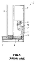
- Fig. 5 is a cross-sectional view of the essential portion of an illustrative coin payment section 1 of the coin processor.
- the coin payment section 1 includes a bottom base 3 having a hole 2 provided for passing a coin therethrough, a payment plate 5 having a hole 4 corresponding in size to the hole 2 in the base 3 and being slidable back and forth (right and left directions in Fig. 5) on the bottom base 3, a coin tube 6 for accommodating the selected coins, a lever 7 for sliding the plate 5 back and forth, and a solenoid 9 having a lever drive shaft 8 for driving the lever 7.
- Fig. 5 shows the solenoid 9 in a deenergized state in which the plate 5 is positioned at a backward position (at a right-hand position in Fig. 5).
- the solenoid 9 When the solenoid 9 is energized, the lever drive shaft 8 is drawn into the solenoid 9 to thereby turns the lever 7 in the clockwise direction around a shaft 10 and hence the plate 5 slides forward (in Fig. 5, leftward).
- the solenoid 9 is deenergized, the lever drive shaft 8 is released from its drawn state to thereby turns the lever 7 in the counterclockwise direction around the shaft 10 and hence the plate 5 returns back to its original position.
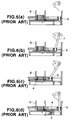
- Figs. 6(a) to 6(d) are cross-sectional views of the essential portion of the coin payment section 1.
- Figs. 6(a) to 6(d) show the respective operations of the coin payment section 1.
- Fig. 6(a) shows the coin payment section in a standby mode, where the coins within the coin tube 6 are placed on a predetermined position at an end of the plate 5.
- the solenoid 9 is energized to turn the lever 7 clockwise as shown in Fig. 6(b)
- the plate 5 starts to slide in the forward direction.
- the plate 5 moves to a predetermined forward position, as shown in Fig. 6(c)
- the lower open end of the coin tube 6 coincides with the hole 4 in the plate 5.
- Fig. 7 is a flowchart showing a conventional processing for coin payment operations. Now, payment of 25-cent coins will be described as a typical example.
- T1 represents a time for which duration the solenoid is deenergized (the waiting time of the plate 5 at the backward position) while T2 represents a time for which duration the solenoid is energized (the waiting time of the plate 5 at the forward position), and a time taken for the plate 5 to slide to the predetermined forward or backward position is not included.
- step 101 it is determined at step 101 whether 25-cent coins are to be paid out. If YES, it is determined at step 102 whether the time T1 has passed by referring to a timer T1. If the T1 has not passed, it means that coins are being paid out and thus the operation waits for the time T1. If the time T1 has passed, a solenoid for 25-cent coins is energized at sep 103 and it is determined at step 104 whether the time T2 has passed by referring to a T2 timer. During the time T2, one coin is taken from the coin tube. When the time T2 has passed at step 104, the 25-cent coin solenoid is deenergized at step 105. By these operations, one coin is paid out.
- control returns to step 101 where the appropriate solenoid starts to be operated after the passage of the time T1. Thereafter, similarly, processing at steps 101-105 is iterated until all the change is paid out. Also, for 5- or 10-cent coins, the processing at steps 106-110 or 111-115 is performed as required.
- the movement of the plate 5 for payment of the coins is determined depending on the timing of energization/deenergization of the solenoid 9.
- the times T1 and T2 are constant at all times irrespective of the number of coins stored in the coin tube.
- the present invention is made in view of the above situation. It is an object of the present invention to provide a coin processor which ensures secure payment of coins at all times without reducing the normal coin payment speed.
- the present invention provides a coin processor which comprises a coin selecting section for discriminating whether inserted coins are genuine or false and denominations of the coins discriminated as genuine ones, and guiding false coins to a predetermined coin passageway and the genuine coins in accordance with their denominations to predetermined coin passageways provided for the respective denominations, a coin accommodating section provided for each denomination for accommodating the genuine coins in accordance with their denominations into corresponding ones thereof, a coin payment section for paying out coins from the coin accommodating section in accordance with an amount of change, detection section for detecting a quantity of coins stored in the coin accommodating section and, time control means for controlling intervals of time for payment of the stored coins depending on the stored quantity of the coins detected by the detection section.
- Fig. 1 is a cross-sectional view of the essential portion of an illustrative coin payment section 11 disposed within a coin processor according to the present invention.
- the coin payment section 11 includes a bottom base 13 having a hole 12 for passing a coin therethrough, a plate 15 provided to be slidable back and forth on the bottom base 13 and having a hole 14 corresponding in size to the hole 12 in the bottom base 13, a coin tube 16 for accommodating selected coins, a sensor 21 for detecting a quantity of coins stored in the coin tube 16, a lever 17 for sliding the plate 15 in back and forth directions and, a solenoid 19 having a lever drive shaft 18 for driving the lever 17.
- the sensor 21 is provided on a lower side of the coin tube 16 so as to detect a quantity of coins within the coin tube 16 through openings 22 formed on a side of the tube. While in the present embodiment an empty sensor is used to detect the quantity of coins, it may be replaced with a change storage quantity counter (number counter) disclosed, for example, in Japanese unexamined patent publication No. 56-11190, an optical sensor or a coil type sensor. In summary, any means or method may be used which is capable of sensing the quantity of coins within the coin tube.
- Fig. 3 is a block diagram of a control system of the coin payment section 11.
- the control system is provided with a sensor 21, a solenoid 19 and, a time controller 23 for controlling the timing of energization/deenergization of the solenoid 19.
- the time controller 23 controls as follows the intervals of time between the operations of the solenoid 19 in accordance with the stored quantity of coins detected by the sensor 21.
- T1 and T3 represent the intervals of time for which the solenoid 19 is in a deenergized state (the waiting time of the plate 15 at the backward standby position) while T2 represents the interval of time for which the solenoid 19 is in an energized state (the waiting time of the plate 15 at the forward standby position).
- T1 400 msec
- T2 100 msec.
- the time controller 23 has timers for the respective times T1, T2 and T3 and refers to the appropriate timer on the basis of the detection of the sensor 21.
- the respective set times for the timers may be changed as required.
- the time controller 23 may include a peripheral circuit which mainly includes a central processing unit (CPU) and a main storage, and a program based on a flowchart to be described later.
- time T2 is shown as being constant to minimize a decrease in the payment speed, it may be increased as required.
- step 201 it is determined at step 201 whether 25-cent coins are to be paid out. If YES, it is determined at step 202 whether there are at least a predetermined quantity of coins. If YES, it is determined at step 203 whether a time T1 has passed by referring to the T1 timer (normally). If NO at step 202, it is determined at step 204 whether the time T3 has passed by referring to the T3 timer. Since in the embodiment the T3 timer has an interval of time is 900 msec which is more than twice the normal interval of time, as mentioned above, the jumped-up coin falls onto the predetermined position at the end of the plate and can be put at the standby position for the next payment.
- the solenoid for a 25-cent coin is energized at step 205 to drop the coin into the hole in the plate. Then, it is determined at step 206 whether the time T2 has passed. If the time T2 has passed, the solenoid for the 25-cent coin is deenergized at step 207. By this series of operations, one coin is paid out. Similarly, the processing at steps 201-207 is then iterated until all the change is paid out. Also, for 10- or 5-cent coins, the processing at steps 208-214 or steps 215-221 is performed as required.
- the time T3 employed when the quantity of coins is small than the predetermined level is not limited to 900 msec, but may be suitable changed depending on the size and/or weight of the coin as required. While in the embodiment the control of payment of change is described in detail, the present invention is not limited to the embodiment. The present invention is applicable to payment of all coins within the coin tube responsive to the inventory operation, returning of inserted coins in accordance with a return command, etc.
Abstract
Description
- The present invention relates to a coin processor for use with vending machines, money exchangers, service machines, etc., for separating inserted coins into genuine ones and false ones, accommodating the genuine coins in accordance with their denominations and paying out the accommodated coins as change.
- Generally, vending machines, money exchangers, service machines, etc., are provided with a coin processor for discriminating whether inserted coins are genuine or false, accommodating the genuine coins in accordance with their denominations and paying out the accommodated coins as change.
- The coin processor is provided with a coin selecting section for separating inserted coins into genuine ones and false ones and further separating the genuine coins in accordance with their denominations. The coin selecting section is provided with complicated coin passageways for classifying the inserted coins as genuine ones or false ones and further separating the genuine coins in accordance with their denominations. The coin selecting section is also provided, on a part of the complicated coin passageway, with a selecting device comprised of a coil sensor having, for example, an oscillating coil and a receiving coil for discriminating whether inserted coins are genuine or false and determining denominations of the genuine coins, and a plurality of levers for guiding the inserted coins to predetermined coin passageways. The selecting device is arranged to separate, while the coins are rolling respectively along the predetermined coin passageways, the inserted coins into the genuine ones and the false ones, to classify the genuine coins in accordance with their denominations and to guide the false ones into a predetermined passage and the genuine coins into predetermined passageways each provided for each of the denominations.
- The genuine coins which have passed through the predetermined passageways are accommodated in accordance with their denominations in a coin accommodating section comprised of coin tubes disposed at a lower portion of the coin processor and, when the denominations of change are specified, the coins in the coin accommodating section are selected in accordance with an amount of the change and paid out downward out of the coin processor.
- Fig. 5 is a cross-sectional view of the essential portion of an illustrative coin payment section 1 of the coin processor. The coin payment section 1 includes a
bottom base 3 having ahole 2 provided for passing a coin therethrough, apayment plate 5 having ahole 4 corresponding in size to thehole 2 in thebase 3 and being slidable back and forth (right and left directions in Fig. 5) on thebottom base 3, acoin tube 6 for accommodating the selected coins, alever 7 for sliding theplate 5 back and forth, and asolenoid 9 having alever drive shaft 8 for driving thelever 7. - Fig. 5 shows the
solenoid 9 in a deenergized state in which theplate 5 is positioned at a backward position (at a right-hand position in Fig. 5). When thesolenoid 9 is energized, thelever drive shaft 8 is drawn into thesolenoid 9 to thereby turns thelever 7 in the clockwise direction around ashaft 10 and hence theplate 5 slides forward (in Fig. 5, leftward). When thesolenoid 9 is deenergized, thelever drive shaft 8 is released from its drawn state to thereby turns thelever 7 in the counterclockwise direction around theshaft 10 and hence theplate 5 returns back to its original position. - Figs. 6(a) to 6(d) are cross-sectional views of the essential portion of the coin payment section 1. Figs. 6(a) to 6(d) show the respective operations of the coin payment section 1. Fig. 6(a) shows the coin payment section in a standby mode, where the coins within the
coin tube 6 are placed on a predetermined position at an end of theplate 5. When thesolenoid 9 is energized to turn thelever 7 clockwise as shown in Fig. 6(b), theplate 5 starts to slide in the forward direction. When theplate 5 moves to a predetermined forward position, as shown in Fig. 6(c), the lower open end of thecoin tube 6 coincides with thehole 4 in theplate 5. Thus, the lowermost one of the coins accommodated in thecoin tube 6 falls into thehole 4 in theplate 5. Thereafter, when thesolenoid 9 is deenergized and thus theplate 5 slides in the backward direction to return to its original position, as shown in Fig. 6(d), thehole 4 in theplate 5 coincides with thehole 2 in thebottom base 3 and the coin in thehole 4 in theplate 5 is paid out downwardly. At this time, the coins remaining within thecoin tube 6 are again placed on the predetermined position at the end of theplate 5, as shown in Fig. 6(a). Thereafter, similar operations are iterated to pay out a required number of coins. - Fig. 7 is a flowchart showing a conventional processing for coin payment operations. Now, payment of 25-cent coins will be described as a typical example. In the following description, T1 represents a time for which duration the solenoid is deenergized (the waiting time of the
plate 5 at the backward position) while T2 represents a time for which duration the solenoid is energized (the waiting time of theplate 5 at the forward position), and a time taken for theplate 5 to slide to the predetermined forward or backward position is not included. - First, it is determined at
step 101 whether 25-cent coins are to be paid out. If YES, it is determined atstep 102 whether the time T1 has passed by referring to a timer T1. If the T1 has not passed, it means that coins are being paid out and thus the operation waits for the time T1. If the time T1 has passed, a solenoid for 25-cent coins is energized atsep 103 and it is determined atstep 104 whether the time T2 has passed by referring to a T2 timer. During the time T2, one coin is taken from the coin tube. When the time T2 has passed atstep 104, the 25-cent coin solenoid is deenergized atstep 105. By these operations, one coin is paid out. When coins are to be successively paid out, control returns tostep 101 where the appropriate solenoid starts to be operated after the passage of the time T1. Thereafter, similarly, processing at steps 101-105 is iterated until all the change is paid out. Also, for 5- or 10-cent coins, the processing at steps 106-110 or 111-115 is performed as required. - As described above, the movement of the
plate 5 for payment of the coins is determined depending on the timing of energization/deenergization of thesolenoid 9. In the conventional coin processor, the times T1 and T2 are constant at all times irrespective of the number of coins stored in the coin tube. - As shown in Fig. 8, when the number of coins stored in the
coin tube 6 decreases, a coin can jump up due to the reaction of the backward movement of theplate 5. If the next payment is performed before the jumped-up coin returns to the predetermined position at the end of theplate 5, no coin would fall into the hole in theplate 5 and normal payment of the coin would not be made disadvantageously. In this case, if the times T1 and T2 are set slightly longer than the conventional set times, the problem would be solved, but the payment speed would be slowed down. Thus, the time taken for the normal payment of coins would become longer accordingly. - The present invention is made in view of the above situation. It is an object of the present invention to provide a coin processor which ensures secure payment of coins at all times without reducing the normal coin payment speed.
- In order to achieve the above object, the present invention provides a coin processor which comprises a coin selecting section for discriminating whether inserted coins are genuine or false and denominations of the coins discriminated as genuine ones, and guiding false coins to a predetermined coin passageway and the genuine coins in accordance with their denominations to predetermined coin passageways provided for the respective denominations, a coin accommodating section provided for each denomination for accommodating the genuine coins in accordance with their denominations into corresponding ones thereof, a coin payment section for paying out coins from the coin accommodating section in accordance with an amount of change, detection section for detecting a quantity of coins stored in the coin accommodating section and, time control means for controlling intervals of time for payment of the stored coins depending on the stored quantity of the coins detected by the detection section.
- The object and advantages of the present invention will easily be confirmed on the basis of the following detailed description and the accompanying drawings.
-
- Fig. 1 is a cross-sectional view of the essential portion of an illustrative coin payment section of a coin processor according to the present invention;
- Fig. 2 is a cross-sectional view taken along the line A-A in Fig. 1;
- Fig. 3 is a block diagram of a control system of the coin payment section;
- Fig. 4 is a flowchart showing the processing of coin payment operations of a time controller;
- Fig. 5 is a cross-sectional view of the essential portion of a coin payment section of a conventional coin processor;
- Figs. 6(a) to 6(d) are cross-sectional views of the essential portion of the conventional coin payment section;
- Fig. 7 is a flowchart showing a conventional processing of coin payment operations; and
- Fig. 8 is a cross-sectional view of the essential portion of the conventional coin payment section.
- One embodiment of a coin processor according to the present invention will be described below.
- Fig. 1 is a cross-sectional view of the essential portion of an illustrative coin payment section 11 disposed within a coin processor according to the present invention.
- The coin payment section 11 includes a
bottom base 13 having ahole 12 for passing a coin therethrough, aplate 15 provided to be slidable back and forth on thebottom base 13 and having ahole 14 corresponding in size to thehole 12 in thebottom base 13, acoin tube 16 for accommodating selected coins, asensor 21 for detecting a quantity of coins stored in thecoin tube 16, alever 17 for sliding theplate 15 in back and forth directions and, asolenoid 19 having alever drive shaft 18 for driving thelever 17. - The basic operations of the
solenoid 19 and lever 17 of the coin payment section 11 are the same as those of the coin payment section 1 of Fig. 6. That is, when thelever drive shaft 18 moves up or down due to energization or deenergization of thesolenoid 19, thelever 17 turns the clockwise or counterclockwise around ashaft 20 to thereby slide theplate 15 in the forward or backward direction. - As shown in Fig. 2, which is a cross-sectional view taken along the line A-A of Fig. 1, the
sensor 21 is provided on a lower side of thecoin tube 16 so as to detect a quantity of coins within thecoin tube 16 throughopenings 22 formed on a side of the tube. While in the present embodiment an empty sensor is used to detect the quantity of coins, it may be replaced with a change storage quantity counter (number counter) disclosed, for example, in Japanese unexamined patent publication No. 56-11190, an optical sensor or a coil type sensor. In summary, any means or method may be used which is capable of sensing the quantity of coins within the coin tube. - Fig. 3 is a block diagram of a control system of the coin payment section 11. The control system is provided with a
sensor 21, asolenoid 19 and, atime controller 23 for controlling the timing of energization/deenergization of thesolenoid 19. Thetime controller 23 controls as follows the intervals of time between the operations of thesolenoid 19 in accordance with the stored quantity of coins detected by thesensor 21. T1 and T3 represent the intervals of time for which thesolenoid 19 is in a deenergized state (the waiting time of theplate 15 at the backward standby position) while T2 represents the interval of time for which thesolenoid 19 is in an energized state (the waiting time of theplate 15 at the forward standby position). When the height of the stored coins exceeds a position of the sensor 21 (normally), the control system delivers an operation signal to thesolenoid 19 at the following timings:


- When the height of the stored coins is below the position of the
sensor 21, the control system changes the setting of the interval of time from T1 to T3 and delivers an operation signal to thesolenoid 19 at the following timings:


- According to this method, since the waiting or standby time of the
plate 15 at the backward position increases, the jumped-up coin will again be placed at the predetermined position on the end of theplate 15. Thus, although payment is performed at the conventional timing, it is achieved securely. - The
time controller 23 has timers for the respective times T1, T2 and T3 and refers to the appropriate timer on the basis of the detection of thesensor 21. The respective set times for the timers may be changed as required. Thetime controller 23 may include a peripheral circuit which mainly includes a central processing unit (CPU) and a main storage, and a program based on a flowchart to be described later. - While in the embodiment the time T2 is shown as being constant to minimize a decrease in the payment speed, it may be increased as required.
- The process of payment of 25-cent coins in the
time controller 23 will be described as a typical example by referring to the flowchart of Fig. 4. - First, it is determined at
step 201 whether 25-cent coins are to be paid out. If YES, it is determined atstep 202 whether there are at least a predetermined quantity of coins. If YES, it is determined atstep 203 whether a time T1 has passed by referring to the T1 timer (normally). If NO atstep 202, it is determined atstep 204 whether the time T3 has passed by referring to the T3 timer. Since in the embodiment the T3 timer has an interval of time is 900 msec which is more than twice the normal interval of time, as mentioned above, the jumped-up coin falls onto the predetermined position at the end of the plate and can be put at the standby position for the next payment. - When either one of the T1 and T3 timers times out, the solenoid for a 25-cent coin is energized at
step 205 to drop the coin into the hole in the plate. Then, it is determined atstep 206 whether the time T2 has passed. If the time T2 has passed, the solenoid for the 25-cent coin is deenergized atstep 207. By this series of operations, one coin is paid out. Similarly, the processing at steps 201-207 is then iterated until all the change is paid out. Also, for 10- or 5-cent coins, the processing at steps 208-214 or steps 215-221 is performed as required. - Thus, even if a coin jumps up due to a backward movement of the plate when the number of stored coins is small, it is given time enough to fall onto the predetermined position at the end of the plate. Thus, when the plate is moved forward by the following payment operation, the coin is ensured to fall into the hole in the plate.
- In the present embodiment, the time T3 employed when the quantity of coins is small than the predetermined level is not limited to 900 msec, but may be suitable changed depending on the size and/or weight of the coin as required. While in the embodiment the control of payment of change is described in detail, the present invention is not limited to the embodiment. The present invention is applicable to payment of all coins within the coin tube responsive to the inventory operation, returning of inserted coins in accordance with a return command, etc.
- As described above, since the time interval of payment is increased automatically when the quantity of coins stored in the coin accommodating section is less than a predetermined quantity, useless operations due to jumping up of coins are prevented which may occur when the storage quantity of coins is less than the predetermined quantity and invariably secure payment is ensured. In addition, since payment is made at normal intervals of time when the storage quantity of coins is more than the predetermined quantity, the normal speed of payment of coins is maintained.
- The present invention can be carried out in other various forms and aspects without departing from its spirit and main features. Thus, the above embodiment is merely illustrative in every respect and should not be interpreted as being restrictive. The scope of the present invention is shown by the attached claims and not at all restricted by the text of the specification. It is to be noted that all changes and modifications falling within the scope of equivalents to the invention defined by the claims fall within the scope of the invention.
Claims (11)
- A coin processor including a coin selecting section for discriminating whether inserted coins are genuine or false and denominations of coins discriminated as genuine ones, and guiding false coins to a predetermined coin passageway and the genuine coins to respective predetermined coin passageways in accordance with their denominations, a coin accommodating section (16) for accommodating the genuine coins in accordance with their denominations and, a coin payment section (11) for paying out from the coin accommodating section (16) coins of denominations corresponding to an amount of change, characterized by:
detection means (21) for detecting a quantity of coins stored in the coin accommodating section (16); and
time control means (23) for controlling an interval of time for payment of the stored coins in accordance with the stored quantity of coins detected by the detection means. - A coin processor according to claim 1, characterized in that the detection means (21) comprises an empty sensor.
- A coin processor according to claim 2, characterized in that the empty sensor is provided in the coin accommodating section (16).
- A coin processor according to claim 3, characterized in that the coin accommodating section (16) has an opening (22) for detecting the stored quantity of coins.
- A coin processor according to claim 1, characterized in that the detection means (21) comprises a number counter and detects the stored quantity of coins on the basis of a content of the number counter.
- A coin processor according to claim 1, characterized in that the time control means (23) sets the interval of time of payment of the stored coins to be longer than a normal time when the stored quantity of coins is less than a predetermined quantity.
- A coin processor including a coin selecting section for discriminating whether inserted coins are genuine or false and denominations of coins discriminated as genuine ones, and guiding false coins to a predetermined coin passageway and the genuine coins to respective predetermined coin passageways in accordance with their denominations, a coin accommodating section (16) for accommodating the genuine coins in accordance with their denominations and, a coin payment section (11) for paying out from the coin accommodating section (16) coins of denominations corresponding to an amount of change, characterized by:
an empty sensor (21) for detecting a quantity of coins stored in the coin accommodating section (16); and
time control means (23) for setting an interval of time for payment of the stored coins to be longer than a normal time when the stored quantity of coins detected by the empty sensor (21) is less than a predetermined quantity. - A coin processor including a coin selecting section for discriminating whether inserted coins are genuine or false and denominations of coins discriminated as genuine ones, and guiding false coins to a predetermined coin passageway and the genuine coins to respective predetermined coin passageways in accordance with their denominations, a coin accommodating section (16) for accommodating the genuine coins in accordance with their denominations and, a coin payment section (11) for paying out from the coin accommodating section (16) coins of denominations corresponding to an amount of change, characterized by:
a number counter (21) for counting a quantity of coins stored in the coin accommodating section (16); and
time control means (23) for setting an interval of time for payment of the stored coins to be longer than a normal time when the stored quantity of coins counted by the number counter (21) is less than a predetermined quantity. - A coin processor including a coin payment section which comprises a bottom base (13) having a hole for passing a coin therethrough, a payment plate (15) having a hole corresponding in size to the hole in the bottom base (13) and disposed so as to be slidable back and forth on the bottom base (13), a coin tube (16) for accommodating genuine-validated coins, a lever (17) for sliding the payment plate (15) back and forth and, a solenoid (19) having a lever drive shaft (18) for driving the lever, characterized by:
detection means (21) for detecting a quantity of coins stored within the coin tube (16); and
time control means (23) for setting a standby time of the payment plate (15) at a backward position to be longer than a normal time when the stored quantity of coins detected by the detection means (21) is less than a predetermined quantity. - A coin processor including a coin payment section which comprises a bottom base (13) having a hole for passing a coin therethrough, a payment plate (15) having a hole corresponding in size to the hole in the bottom base and disposed so as to be slidable back and forth on the bottom base (13), a coin tube (16) for accommodating genuine-validated coins, a lever (17) for sliding the payment plate (15) back and forth and, a solenoid (19) having a lever drive shaft (18) for driving the lever, characterized by:
an empty sensor (21) for detecting a quantity of coins stored in the coin tube (16); and
time control means (23) for setting a standby time of the payment plate (15) at a backward position to be longer than a normal time when the stored quantity of coins detected by the empty sensor (21) is less than a predetermined quantity. - A coin processor including a coin payment section which comprises a bottom base (13) having a hole for passing a coin therethrough, a payment plate (15) having a hole corresponding in size to the hole in the bottom base (13) and disposed so as to be slidable back and forth on the bottom base, a coin tube (16) for accommodating genuine-validated coins, a lever (17) for sliding the payment plate (15) back and forth and, a solenoid (19) having a lever drive shaft (18) for driving the lever (17), characterized by:
a number counter (21) for counting a quantity of coins stored in the coin tube (16); and
time control means (23) for setting a standby time of the plate (17) at a backward position to be longer than a normal time when the stored quantity of coins counted by the number counter (21) is less than a predetermined quantity.
Applications Claiming Priority (2)
| Application Number | Priority Date | Filing Date | Title |
|---|---|---|---|
| JP4120757A JPH05346982A (en) | 1992-05-13 | 1992-05-13 | Coin processing device |
| JP120757/92 | 1992-05-13 |
Publications (3)
| Publication Number | Publication Date |
|---|---|
| EP0569956A2 true EP0569956A2 (en) | 1993-11-18 |
| EP0569956A3 EP0569956A3 (en) | 1994-08-24 |
| EP0569956B1 EP0569956B1 (en) | 1997-02-26 |
Family
ID=14794242
Family Applications (1)
| Application Number | Title | Priority Date | Filing Date |
|---|---|---|---|
| EP93107699A Expired - Lifetime EP0569956B1 (en) | 1992-05-13 | 1993-05-12 | Coin processor |
Country Status (7)
| Country | Link |
|---|---|
| US (1) | US5460568A (en) |
| EP (1) | EP0569956B1 (en) |
| JP (1) | JPH05346982A (en) |
| KR (1) | KR970005403B1 (en) |
| AU (1) | AU651762B2 (en) |
| CA (1) | CA2095977C (en) |
| DE (1) | DE69308231T2 (en) |
Families Citing this family (4)
| Publication number | Priority date | Publication date | Assignee | Title |
|---|---|---|---|---|
| JP3438083B2 (en) * | 1994-10-28 | 2003-08-18 | 株式会社日本コンラックス | Coin payout device |
| JP4355475B2 (en) * | 2002-07-26 | 2009-11-04 | 株式会社日本コンラックス | Coin processing apparatus and control method thereof |
| CN1685372A (en) * | 2003-12-12 | 2005-10-19 | 有限会社水贝总业 | Dispencer for coin or its kind |
| JP4501825B2 (en) * | 2005-09-21 | 2010-07-14 | 富士電機リテイルシステムズ株式会社 | Coin processing equipment |
Citations (3)
| Publication number | Priority date | Publication date | Assignee | Title |
|---|---|---|---|---|
| US4616323A (en) * | 1983-02-23 | 1986-10-07 | Kabushiki Kaisha Nippon Coinco. | Control device and a method for sending and receiving information in a vending machine and the like apparatus |
| US4706202A (en) * | 1984-09-07 | 1987-11-10 | Nippon Coinco Co., Ltd. | Control system of a vending machine |
| EP0397353A2 (en) * | 1989-05-09 | 1990-11-14 | Sanden Corporation | Coin return control system for vending machines |
Family Cites Families (20)
| Publication number | Priority date | Publication date | Assignee | Title |
|---|---|---|---|---|
| US3215151A (en) * | 1965-11-02 | Coin separators | ||
| DE2035971A1 (en) * | 1969-07-22 | 1971-04-08 | Expert Ind Controls Ltd | Device for issuing coins |
| ZA731072B (en) * | 1972-02-23 | 1973-11-28 | Mars Inc | Coin dispenser |
| DE2334664A1 (en) * | 1973-07-07 | 1975-01-30 | Alfred Krauth Apparatebau Kg P | Coin dispensing mechanism - discharges coins one at a time from the front at an electronic signal |
| US3935873A (en) * | 1974-07-19 | 1976-02-03 | U.M.C. Industries, Inc. | Coin-dispensing device |
| GB1505084A (en) * | 1974-10-07 | 1978-03-22 | H R Electronics Co | Colin controlled devices for use in vending machines |
| US4010765A (en) * | 1976-03-01 | 1977-03-08 | Reed Industries, Inc. | Coin changer with spring-biased slides |
| JPS6057626B2 (en) * | 1976-04-30 | 1985-12-16 | 株式会社日本コインコ | Vending machine control device |
| JPS586054Y2 (en) * | 1977-10-21 | 1983-02-02 | 株式会社日本コインコ | Coin dispensing device |
| GB2043317B (en) * | 1979-03-01 | 1983-03-23 | Mars Inc | Coin dispenser |
| JPS5846751B2 (en) * | 1979-03-09 | 1983-10-18 | 松下電器産業株式会社 | Coin dispensing device |
| US4361161A (en) * | 1979-05-04 | 1982-11-30 | Umc Industries, Inc. | Coin handling device |
| US4257436A (en) * | 1979-07-25 | 1981-03-24 | Umc Industries, Inc. | Coin dispensing apparatus having a U-shaped coin ejector |
| US4266564A (en) * | 1979-10-01 | 1981-05-12 | Orin W. Coburn | Coin release assembly |
| US4313450A (en) * | 1979-12-21 | 1982-02-02 | Fuji Electric Co., Ltd. | Coin-dispensing device |
| GB8300671D0 (en) * | 1983-01-11 | 1983-02-09 | Starpoint Electrics Ltd | Gaming machines |
| KR900007889B1 (en) * | 1983-09-06 | 1990-10-22 | 가부시기가이샤 닛본 곤락스 | Coin guidance machine |
| US4834689A (en) * | 1987-01-28 | 1989-05-30 | Coin Acceptors, Inc. | Coin changer payout means |
| US5011456A (en) * | 1988-06-22 | 1991-04-30 | Kabushiki Kaisha Nippon Conlux | Coin receiving and discharging apparatus |
| JPH0644305B2 (en) * | 1990-06-13 | 1994-06-08 | 旭精工株式会社 | Coin sending device |
-
1992
- 1992-05-13 JP JP4120757A patent/JPH05346982A/en active Pending
-
1993
- 1993-05-04 KR KR1019930007615A patent/KR970005403B1/en not_active IP Right Cessation
- 1993-05-10 US US08/059,648 patent/US5460568A/en not_active Expired - Lifetime
- 1993-05-11 CA CA002095977A patent/CA2095977C/en not_active Expired - Fee Related
- 1993-05-12 DE DE69308231T patent/DE69308231T2/en not_active Expired - Fee Related
- 1993-05-12 EP EP93107699A patent/EP0569956B1/en not_active Expired - Lifetime
- 1993-05-12 AU AU38544/93A patent/AU651762B2/en not_active Ceased
Patent Citations (3)
| Publication number | Priority date | Publication date | Assignee | Title |
|---|---|---|---|---|
| US4616323A (en) * | 1983-02-23 | 1986-10-07 | Kabushiki Kaisha Nippon Coinco. | Control device and a method for sending and receiving information in a vending machine and the like apparatus |
| US4706202A (en) * | 1984-09-07 | 1987-11-10 | Nippon Coinco Co., Ltd. | Control system of a vending machine |
| EP0397353A2 (en) * | 1989-05-09 | 1990-11-14 | Sanden Corporation | Coin return control system for vending machines |
Also Published As
| Publication number | Publication date |
|---|---|
| EP0569956B1 (en) | 1997-02-26 |
| US5460568A (en) | 1995-10-24 |
| DE69308231T2 (en) | 1997-09-04 |
| KR970005403B1 (en) | 1997-04-16 |
| KR930023890A (en) | 1993-12-21 |
| AU3854493A (en) | 1993-11-25 |
| CA2095977A1 (en) | 1993-11-14 |
| JPH05346982A (en) | 1993-12-27 |
| CA2095977C (en) | 1997-07-08 |
| AU651762B2 (en) | 1994-07-28 |
| EP0569956A3 (en) | 1994-08-24 |
| DE69308231D1 (en) | 1997-04-03 |
Similar Documents
| Publication | Publication Date | Title |
|---|---|---|
| EP0477722B1 (en) | Coin processing apparatus | |
| US5579886A (en) | Coin processor | |
| US4228811A (en) | Apparatus for controlling a coin sorting machine | |
| US5219059A (en) | Coin processing apparatus | |
| US3978962A (en) | Solid state, coin activated mechanism | |
| JPH09504128A (en) | Coin handling device that controls the discharge of coins | |
| JPH03137782A (en) | Method and device for detecting coin | |
| JP5261655B2 (en) | Value medium processing device | |
| EP0569956B1 (en) | Coin processor | |
| JP2009193375A5 (en) | ||
| EP0447890B1 (en) | Monochannel device for control, storage and collection of coins | |
| JPH0637502Y2 (en) | Coin handling equipment | |
| JP3121483B2 (en) | Coin processing equipment | |
| US5026972A (en) | Automatic toll receiving apparatus | |
| JP3175359B2 (en) | Coin mechanism with change adjustment function | |
| JP2936283B2 (en) | Coin processing equipment | |
| JP2887433B2 (en) | Coin processing equipment | |
| AU641549B2 (en) | Coin processing apparatus | |
| JP2517284B2 (en) | Currency storage control device for vending machines | |
| KR820001896B1 (en) | Coins accumulation disposal method | |
| CA2161269C (en) | Coin processing apparatus | |
| JP3030564B2 (en) | Coin processing equipment | |
| JP2001283276A (en) | Coin processing method and coin processor | |
| JPH04184591A (en) | Coin processor | |
| JPH07272046A (en) | Coin processing device |
Legal Events
| Date | Code | Title | Description |
|---|---|---|---|
| PUAI | Public reference made under article 153(3) epc to a published international application that has entered the european phase |
Free format text: ORIGINAL CODE: 0009012 |
|
| 17P | Request for examination filed |
Effective date: 19930512 |
|
| AK | Designated contracting states |
Kind code of ref document: A2 Designated state(s): DE ES FR GB IT |
|
| PUAL | Search report despatched |
Free format text: ORIGINAL CODE: 0009013 |
|
| AK | Designated contracting states |
Kind code of ref document: A3 Designated state(s): DE ES FR GB IT |
|
| 17Q | First examination report despatched |
Effective date: 19950724 |
|
| GRAG | Despatch of communication of intention to grant |
Free format text: ORIGINAL CODE: EPIDOS AGRA |
|
| GRAH | Despatch of communication of intention to grant a patent |
Free format text: ORIGINAL CODE: EPIDOS IGRA |
|
| GRAH | Despatch of communication of intention to grant a patent |
Free format text: ORIGINAL CODE: EPIDOS IGRA |
|
| GRAA | (expected) grant |
Free format text: ORIGINAL CODE: 0009210 |
|
| AK | Designated contracting states |
Kind code of ref document: B1 Designated state(s): DE ES FR GB IT |
|
| PG25 | Lapsed in a contracting state [announced via postgrant information from national office to epo] |
Ref country code: IT Free format text: LAPSE BECAUSE OF FAILURE TO SUBMIT A TRANSLATION OF THE DESCRIPTION OR TO PAY THE FEE WITHIN THE PRESCRIBED TIME-LIMIT;WARNING: LAPSES OF ITALIAN PATENTS WITH EFFECTIVE DATE BEFORE 2007 MAY HAVE OCCURRED AT ANY TIME BEFORE 2007. THE CORRECT EFFECTIVE DATE MAY BE DIFFERENT FROM THE ONE RECORDED. Effective date: 19970226 Ref country code: ES Free format text: THE PATENT HAS BEEN ANNULLED BY A DECISION OF A NATIONAL AUTHORITY Effective date: 19970226 |
|
| REF | Corresponds to: |
Ref document number: 69308231 Country of ref document: DE Date of ref document: 19970403 |
|
| ET | Fr: translation filed | ||
| PLBE | No opposition filed within time limit |
Free format text: ORIGINAL CODE: 0009261 |
|
| STAA | Information on the status of an ep patent application or granted ep patent |
Free format text: STATUS: NO OPPOSITION FILED WITHIN TIME LIMIT |
|
| 26N | No opposition filed | ||
| REG | Reference to a national code |
Ref country code: GB Ref legal event code: IF02 |
|
| PGFP | Annual fee paid to national office [announced via postgrant information from national office to epo] |
Ref country code: DE Payment date: 20070510 Year of fee payment: 15 |
|
| PGFP | Annual fee paid to national office [announced via postgrant information from national office to epo] |
Ref country code: GB Payment date: 20070509 Year of fee payment: 15 |
|
| PGFP | Annual fee paid to national office [announced via postgrant information from national office to epo] |
Ref country code: FR Payment date: 20070510 Year of fee payment: 15 |
|
| GBPC | Gb: european patent ceased through non-payment of renewal fee |
Effective date: 20080512 |
|
| REG | Reference to a national code |
Ref country code: FR Ref legal event code: ST Effective date: 20090119 |
|
| PG25 | Lapsed in a contracting state [announced via postgrant information from national office to epo] |
Ref country code: FR Free format text: LAPSE BECAUSE OF NON-PAYMENT OF DUE FEES Effective date: 20080602 Ref country code: DE Free format text: LAPSE BECAUSE OF NON-PAYMENT OF DUE FEES Effective date: 20081202 |
|
| PG25 | Lapsed in a contracting state [announced via postgrant information from national office to epo] |
Ref country code: GB Free format text: LAPSE BECAUSE OF NON-PAYMENT OF DUE FEES Effective date: 20080512 |