EP0570092A1 - Apparatus and method for processing image data - Google Patents
Apparatus and method for processing image data Download PDFInfo
- Publication number
- EP0570092A1 EP0570092A1 EP19930301463 EP93301463A EP0570092A1 EP 0570092 A1 EP0570092 A1 EP 0570092A1 EP 19930301463 EP19930301463 EP 19930301463 EP 93301463 A EP93301463 A EP 93301463A EP 0570092 A1 EP0570092 A1 EP 0570092A1
- Authority
- EP
- European Patent Office
- Prior art keywords
- data
- streams
- split
- stream
- manipulation
- Prior art date
- Legal status (The legal status is an assumption and is not a legal conclusion. Google has not performed a legal analysis and makes no representation as to the accuracy of the status listed.)
- Granted
Links
- 238000000034 method Methods 0.000 title claims abstract description 34
- 238000012545 processing Methods 0.000 title claims abstract description 20
- 238000011064 split stream procedure Methods 0.000 claims abstract description 54
- 238000001914 filtration Methods 0.000 claims description 7
- 238000004519 manufacturing process Methods 0.000 abstract description 12
- 238000012544 monitoring process Methods 0.000 description 15
- 238000005070 sampling Methods 0.000 description 11
- 239000000872 buffer Substances 0.000 description 9
- 230000000694 effects Effects 0.000 description 9
- 238000013459 approach Methods 0.000 description 5
- 230000006798 recombination Effects 0.000 description 4
- 238000005215 recombination Methods 0.000 description 4
- 101100521334 Mus musculus Prom1 gene Proteins 0.000 description 2
- 238000006243 chemical reaction Methods 0.000 description 2
- 230000003247 decreasing effect Effects 0.000 description 2
- 238000013507 mapping Methods 0.000 description 2
- 230000003139 buffering effect Effects 0.000 description 1
- 238000011161 development Methods 0.000 description 1
- 238000010894 electron beam technology Methods 0.000 description 1
- 239000000284 extract Substances 0.000 description 1
- 238000012986 modification Methods 0.000 description 1
- 230000004048 modification Effects 0.000 description 1
- 238000003860 storage Methods 0.000 description 1
- 230000002123 temporal effect Effects 0.000 description 1
- 238000012546 transfer Methods 0.000 description 1
Images


Classifications
-
- H—ELECTRICITY
- H04—ELECTRIC COMMUNICATION TECHNIQUE
- H04N—PICTORIAL COMMUNICATION, e.g. TELEVISION
- H04N7/00—Television systems
- H04N7/12—Systems in which the television signal is transmitted via one channel or a plurality of parallel channels, the bandwidth of each channel being less than the bandwidth of the television signal
-
- H—ELECTRICITY
- H04—ELECTRIC COMMUNICATION TECHNIQUE
- H04N—PICTORIAL COMMUNICATION, e.g. TELEVISION
- H04N19/00—Methods or arrangements for coding, decoding, compressing or decompressing digital video signals
- H04N19/60—Methods or arrangements for coding, decoding, compressing or decompressing digital video signals using transform coding
- H04N19/63—Methods or arrangements for coding, decoding, compressing or decompressing digital video signals using transform coding using sub-band based transform, e.g. wavelets
-
- H—ELECTRICITY
- H04—ELECTRIC COMMUNICATION TECHNIQUE
- H04N—PICTORIAL COMMUNICATION, e.g. TELEVISION
- H04N5/00—Details of television systems
- H04N5/222—Studio circuitry; Studio devices; Studio equipment
- H04N5/262—Studio circuits, e.g. for mixing, switching-over, change of character of image, other special effects ; Cameras specially adapted for the electronic generation of special effects
- H04N5/272—Means for inserting a foreground image in a background image, i.e. inlay, outlay
-
- H—ELECTRICITY
- H04—ELECTRIC COMMUNICATION TECHNIQUE
- H04N—PICTORIAL COMMUNICATION, e.g. TELEVISION
- H04N5/00—Details of television systems
- H04N5/76—Television signal recording
- H04N5/91—Television signal processing therefor
- H04N5/92—Transformation of the television signal for recording, e.g. modulation, frequency changing; Inverse transformation for playback
- H04N5/926—Transformation of the television signal for recording, e.g. modulation, frequency changing; Inverse transformation for playback by pulse code modulation
-
- H—ELECTRICITY
- H04—ELECTRIC COMMUNICATION TECHNIQUE
- H04N—PICTORIAL COMMUNICATION, e.g. TELEVISION
- H04N5/00—Details of television systems
- H04N5/76—Television signal recording
- H04N5/91—Television signal processing therefor
- H04N5/93—Regeneration of the television signal or of selected parts thereof
- H04N5/937—Regeneration of the television signal or of selected parts thereof by assembling picture element blocks in an intermediate store
-
- H—ELECTRICITY
- H04—ELECTRIC COMMUNICATION TECHNIQUE
- H04N—PICTORIAL COMMUNICATION, e.g. TELEVISION
- H04N19/00—Methods or arrangements for coding, decoding, compressing or decompressing digital video signals
- H04N19/30—Methods or arrangements for coding, decoding, compressing or decompressing digital video signals using hierarchical techniques, e.g. scalability
-
- H—ELECTRICITY
- H04—ELECTRIC COMMUNICATION TECHNIQUE
- H04N—PICTORIAL COMMUNICATION, e.g. TELEVISION
- H04N5/00—Details of television systems
- H04N5/76—Television signal recording
- H04N5/84—Television signal recording using optical recording
- H04N5/843—Television signal recording using optical recording on film
Definitions
- This invention relates to the processing of image data.
- Image data can be captured in many different forms.
- image data may be captured by still/moving image photographic cameras or still/moving image electronic cameras.
- image data is typically transformed into a stream of data according to a known image data format, such as PAL, NTSC, SECAM or SMPTE 240M.
- the manipulations can take many different forms.
- the manipulation may be recording onto magnetic tape, processing through a digital video effects system, motion compensated standards conversion or spatial filtering.
- this technical field is at the start of a transitional period between the use of formats such as PAL, NTSC and SECAM and the use of a new generation of high definition of video formats.
- One possible way in which the use of higher resolution formats may be facilitated is to split the source stream of data into a number of separate split streams of data each having only part of the information content of the source stream of data.
- the lowering of the information content of the split streams of data may be sufficient to allow existing or slightly modified equipment, originally designed for use with lower resolution formats, to be employed.
- This technique can be thought of as providing a hierarchial philosophy in which systems of increased resolution can be built from combining pieces of equipment that were originally produced for lower resolution operation.
- the invention provides apparatus for processing image data, said apparatus comprising: an image data source for generating a source stream of data representing an image; a data splitter for splitting said source stream of data into a plurality of split streams of data each representing a part of the information content of said source stream of data; manipulation means for performing a manipulation upon said plurality of split streams of data; and a data combiner for combining said plurality of split streams of data into an output stream of data; wherein said manipulation means includes at least one reformatter for reformatting said plurality of split streams of data such that the information content of said source stream of data is split between said plurality of split streams according to a different technique that is matched to a manipulation to be applied to said plurality of split data streams.
- the invention both recognizes and solves the problem that differing ways of splitting the image data are suited to some, but not other, forms of manipulation prior to recombination.
- the provision of a system in which the manipulation means includes at least one reformatter greatly increases the versatility of the system whilst only incurring a minor increase in complexity.
- the data splitter and data combiner may use many different splitting techniques.
- An 'ad hoc' approach could be used to provide whatever interfaces were needed between different items of manipulation apparatus so as to change the data splitting format. This would however cause problems by preventing a uniform approach to monitoring the signal at different points along the processing chain.
- a better approach is to provide a uniform format for the exchange of data between manipulation apparatus and then provide each manipulating apparatus requiring other than this uniform format with reformatters at its input and output to reformat out of and then back in to the uniform format.
- the differing splitting techniques that may be used each have associated advantages and disadvantages. Splitting the data by sub sampling is simple to implement, but the monitor signals are generally not of high quality. Splitting the data by tiling is still relatively easy to implement and has the advantage that standard concealment of errors can be used, but has the disadvantage that monitoring is not that straight forward and edge effects may be visible upon recombination.
- said data splitter includes means for splitting said source stream of data into a plurality of streams of two dimensional spatial frequency sub band data and said data combiner includes means for combining said plurality of streams of two dimensional spatial frequency sub band data to form said output stream of data.
- Splitting the data on a spatial frequency basis can be achieved by using relatively simple and inexpensive filters. Furthermore, since each sub band has its edge corresponding to the edge of the full image, this approach is not prone to introducing edge effect errors into the central part of the reconstructed image.
- the sub band splitting technique is particularly suitable when said manipulation means includes an image data recorder for separately recording said plurality of streams of two dimensional spatial frequency sub band data and monitor means for reproducing a monitor image during partial replay from that stream of two dimensional sub band data having the lowest two dimensional spatial frequencies.
- the monitoring of the image is of critical importance when carrying out tasks such as editing with manipulations from a digital video effects unit and this feature allows one of the recorded channels to be used to provide a good quality monitor image.
- said data splitter is operable to provide that stream of two dimensional sub band data having the lowest two dimensional spatial frequencies with a signal format suitable for direct reproduction by a television receiver.
- This feature allows the sub band data having the lowest two-dimensional spatial frequencies to be directly tapped and displayed upon a conventional television receiver.
- This monitor image will be of a lower resolution than the source stream of data, but it is quite sufficient for the function of locating particular points within an image data stream.
- sub band splitting has advantages in circumstances such as those described above, it suffers from the limitation that any manipulation that alters the spatial frequency of any of the data in the split streams of data would introduce a gross distortion on recombination. Furthermore, any manipulation involving spatial filtering would have a disadvantageously decreased resolution due to the decreased spatial resolution of the individual split streams of data upon which it would operate.
- said at least one reformatter includes means for reformatting said plurality of split streams of data into a plurality of streams of data each representing a different area within an image.
- Embodiments of the invention with a reformatter capable of providing tiled data are particularly suitable when said manipulation means includes a spatial filtering means for performing spatial filtering separately upon said plurality of streams of data representing different areas of an image.
- said at least one reformatter includes means for reformatting said plurality of split streams of data into a plurality of streams of sub sampled data.
- one class of preferred embodiments provide that said manipulation means has a multichannel architecture with said plurality of split streams of data each being manipulated in a different channel so as to provide real time manipulation of said image data.
- preferred hardware efficient embodiments of the invention are such that said data splitter outputs a multiplexed stream of data comprising a sequence of contemporaneous portions of said plurality of split streams of data, said manipulation means performing non real time manipulation upon said multiplexed stream of data.
- the invention also provides a method of processing image data, said method comprising the steps of: generating a source stream of data representing an image; splitting said source stream of data into a plurality of split streams of data each representing a part of the information content of said source stream of data; reformatting said plurality of split streams of data such that the information content of said source stream of data is split between said plurality of split streams of data according to a different technique that is matched to a subsequent manipulation ; performing a manipulation upon said plurality of split streams of data; and combining said plurality of split streams of data into an output stream of data.
- Figure 1 illustrates a system for the non real time manipulation of image data.
- Various apparatus for generating the source stream of image data is illustrated. These include: a still image photographic camera 2 and a slide converter 4; a movie camera 6 and a film scanner 8; a high definition moving image electronic camera 10, a high definition digital video tape recorder 12 and a video data mixer 14; and a super high resolution moving image electronic video camera 16 and a super high resolution digital video tape recorder 18 (illustrating the hierarchial manner in which the system can cope with increased resolution equipment developed in the future).
- the image capture of these devices takes place in real time. Subsequent processing in this embodiment takes place in non real time.
- the factor by which the processing time is reduced is approximately equal to the number of streams into which the data is split.
- the non real time source stream of data from one of the slide scanner 4, the film scanner 8 or the video data mixer 14 is fed to a respective data splitter 20.
- the split streams of data from the data splitter 20 take the form of a multiplexed stream of data comprising a sequence of contemporaneous portions of each of the split streams, e.g. the image data from a single frame may be split into four separate streams which are then output in sequence from the data splitter 20.
- the non real time multiplexed data streams from the data splitter 20 are recorded on a high definition digital video tape recorder 22. In the case of the super high resolution camera 16 and the super high resolution digital video tape recorder 18, the super high resolution digital video tape recorder captures the image data in real time but plays it back through the data splitter 20 in non real time.
- the split data is then fed to a post production processing unit 24.
- This post production processing unit can be a standard piece of high definition equipment such as a high definition video effects unit or high definition filtering system.
- the manipulation being performed could be the storage on magnetic media by the high definition digital video tape recorder 22.
- the output from the post production processing unit 24 is fed to a further high definition digital video tape recorder 26 via which it is passed to a data combiner 28.
- the data combiner 28 combines the split streams of data into an output stream of data. This can then be passed through a super high resolution film transfer unit 30 onto a 70mm film projection system 32 or direct to a super high resolution video channel 34.
- the combined output stream of data could be split again with accompanying pan/scan/zoom operations by a video down conversion system 36 and then displayed via a standard high definition channel 38 or placed onto 35mm film by an electron beam recorder 40.
- Figure 2 shows a system for the real time manipulation of image data.
- the difference between this system and that of Figure 1 is that between the data splitters 20 and the data combiners 28 there exists a multi channel architecture comprising four post production processing units 24 with corresponding banks of high definition video tape recorders 22 and 26.
- the four post production processing units 24 must have a coordinated operation and so a controller 42 is provided to synchronise their operation. For example, if the post production processing unit is performing a fade or wipe operation then it is important that this should progress at the same rate for each of the split streams of data if distortion upon recombination is to be avoided.
- Figure 3 illustrates a super high resolution frame of video data. This is approximately four times the resolution of current high definition video (two times horizontal and two times vertical) and has 2007 horizontal lines each composed of 3840 pixels.
- Figure 4 illustrates how the super high resolution frame of Figure 3 may be split into four two dimensional spatial frequency sub bands.
- the image is split into low and high frequency components both horizontally and vertically.
- Sub band 44 is the low horizontal and low vertical frequency component.
- Sub band 46 is the low horizontal and high vertical frequency component.
- Sub band 48 is the high horizontal and low vertical frequency component.
- Sub band 50 is the high horizontal and high vertical frequency component. It will be appreciated that since the super high resolution frame of Figure 3 has essentially double the horizontal and vertical spatial frequency of a standard high definition video frame, the splitting by a factor of four will mean that the sub band 44 in fact represents a high definition base band image.
- Sub band 52 is the first sub band of the next frame of image data.
- FIG. 5 illustrates a data splitter 20 for sub band splitting.
- the super high resolution source stream of data is fed into a filter bank 54.
- the filter bank 54 comprises an array of finite impulse response filters of the known type for decimating and frequency separating the input data stream.
- the output from the filter bank 54 is four parallel split streams of data each representing a different spatial frequency sub band.
- these split streams of data are fed in parallel to the multi channel post production processing system.
- they are fed to a buffer and selector unit 56 where they are collected and sequentially fed onto the single high definition video channel for post production processing with the system of Figure 1.
- Figure 6 shows a data combiner 28 for use with split streams of data produced with the sub band splitting technique.
- the split streams of data are fed in parallel to a filter bank 58 where they are combined and interpolated into a super high resolution signal.
- the parallel channels pass through a selector and buffer unit 60 without modification.
- the multiplexed split streams of data are fed via a sequential channel to the selector and buffer unit 60 where they are fed into appropriate buffer stores for subsequent parallel output to the filter bank 58 during the next frame period whilst another set of buffers are receiving the split streams for that next frame.
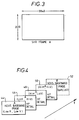
- Figure 7 illustrates the splitting of a super high resolution frame with a tiling splitting technique. Different portions of the image A1, A2, A3 and A4 are formed in respective quadrants. It will be seen that these quadrants overlap. This overlapping is to facilitate the removal of edge effect distortions when the quadrants are subsequently recombined.
- FIG 8 illustrates the split streams of data formed with this tiling splitting technique.
- Each stream of data represents a respective quadrant from within the super high resolution frame of Figure 7.
- Quadrant B1 represents the upper left hand quadrant of the subsequent super high resolution frame.
- FIG. 9 illustrates a non real time data splitter 20 for use with either tiling or sub sampling splitting.
- the super high resolution data is fed to a swing buffer arrangement 62. Respective frames of the super high resolution data are stored in respective frame stores on either side of the swing buffer 62.
- a timing circuit 64 extracts the timing and synchronisation information from the super high resolution signal. This timing circuit controls the operation of a read address generator 66 and a write address generator 68.
- the read address generator 66 and the write address generator 68 can comprise incrementing counters addressing appropriately programmed PROMs for mapping the incrementing count into a predetermined sequence of addresses within the frame stores of the swing buffer 62. Whilst a current frame of super high resolution data is being fed into one of the frame stores under control of the write address generator 68, the data from the previous frame is being read out of the other frame store under control of the read address generator 66.
- the data can be read into the frame stores in its normal raster scan pattern but read out in any sequence and order that is desired.
- the data can be read out as four raster scanned quadrants in the case of tiling splitting or in a raster scanned spatially sub sampled sequence in the case of sub sampling splitting as will be discussed later.
- a select and control unit 70 responsive to the respective read and write addresses is used to supply the appropriate signals to the control inputs of the frame stores and to an output selector 72.
- Figure 10 illustrates a real time version of the data splitter of Figure 9.
- four parallel swing buffers are provided.
- the splitting can take place on either the input side or output side of the frame stores.
- the full image could be written into each frame store and then the appropriate pixels thereof read out under control of the predetermined sequence of read addresses.
- only those pixels for a particular split data stream could be read into each of the frame stores and then all of these read out in parallel with a simple incrementing read address.
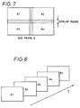
- Figure 11 illustrates a sub sampling splitting technique.
- the pixels from a small section of a super high resolution frame are shown in magnified schematic form at the bottom of Figure 11.
- the pixels for the respective split streams of data are shown as °, ⁇ , ⁇ , and ⁇ . It will be seen that the pixels forming each of the split streams of data effectively sub sample the full super high resolution frame in a regular array.
- Figure 12 shows the split streams of data collected together. Respective split streams comprise all the °, ⁇ , ⁇ and ⁇ pixels from one super high resolution frame.
- Figure 13 illustrates a manipulation means for manipulating a foreground image and keying it into a background image.
- a data splitter 92 splits the foreground image data stream into a series of consecutive sub band image as shown in Figure 4 (sub band splitting is, in this embodiment, used as the uniform data exchange format between manipulation apparatus). These sub band images as then stored on a video tape recorder 94. It is desired that the foreground image be scaled prior to combination with the background image. This scaling will alter the spatial frequencies within the image and accordingly cannot be carried out in the sub band domain.
- a reformatter 96 converts the data from a sub band format to a tiled format as illustrated in Figure 7. The output from the reformatter 96 is then scaled in the digital multiple effects unit 98 prior to being reformatted back into sub band format by the reformatter 100.
- a background image is split into sub band format by a data splitter 102 prior to being stored on a video tape recorder 104.
- the outputs from the reformatter 100 and the video tape recorder 104 are fed to the inputs of a keyer 106 where they are keyed together in the sub band domain under the control of a keying signal prior to being combined into an output data stream by a data combiner 108.
- a monitor 110 is provided to read the LowH, LowV sub band (see Figure 4) so as to provide feedback to the operator as to the results of the DME scaling and keying manipulations.
- the reformatters 96, 100 can be constructed using the data splitters and data combiners described above in relation to Figures 5, 6, 9 and 10.
- the reformatter 96 (sub band to tiled) can be formed as a sub band combiner in series with a tiling splitter and the reformatter 100 (tiled to sub band) as a tiling combiner in series with a sub band splitter.
- Figure 14 illustrates the monitoring of non real time sub band split data.
- the sequential stream of multiplexed sub band data is selectively sampled into a frame store 74.
- the sync input to the frame store 74 ensures that it is the low frequency horizontal and low frequency vertical sub band data that is captured in the frame store 74.
- This particular sub band represents a base band high definition video signal that can be directly used to drive a standard high definition monitor 76.
- Figure 15 illustrates monitoring in a real time sub band splitting system.
- the low frequency horizontal and low frequency vertical sub band data be can directly tapped to a high definition monitor 78 with no need for the buffering of the frame store 74 from the non real time system.
- Figure 16 illustrates monitoring in a non real time tiling splitting system. Successive quadrants of a source image frame are captured in a frame store 80. This captured data is then refiltered to remove any edge effects and decimated down to a high definition signal which can then be used to drive a high definition monitor 82.
- Figure 17 shows monitoring in a real time tiling splitting system.
- the quadrants are captured in parallel, but otherwise the steps of combination, refiltering and decimation are the same.
- Figures 18 and 19 respectively illustrate non real time and real time monitoring in a sub sampling splitting system. These monitoring systems are substantially the same as those of Figures 15 and 16 other than the data is in a different order within each split stream.
- Figures 20, 21 and 22 illustrate possible post production manipulations that may be performed. All the images are of a super high resolution format of the form illustrated in Figure 3.
- Figure 19 has a background 83 formed of an expanded and defocused high definition image with a foreground image 84 subsequently matted on at its full super high resolution.
- Figure 21 shows a super high resolution background 86 with a high definition foreground 88 matted on at its full high definition resolution.
- Figure 22 shows a high definition image that has been magnified horizontally and vertically to fill a full super high resolution frame 90.
Abstract
Description
- This invention relates to the processing of image data.
- The processing of image data is a well established technical field. Image data can be captured in many different forms. For example, image data may be captured by still/moving image photographic cameras or still/moving image electronic cameras. Once the image data has been captured, it is typically transformed into a stream of data according to a known image data format, such as PAL, NTSC, SECAM or SMPTE 240M.
- There exist many different pieces of equipment for performing manipulations upon image data in the aforementioned formats. The manipulations can take many different forms. For example, the manipulation may be recording onto magnetic tape, processing through a digital video effects system, motion compensated standards conversion or spatial filtering.
- As the technical field of the capture, manipulation and reproduction of image data has advanced, this has made possible the use of increasingly high resolution systems. At the present time this technical field is at the start of a transitional period between the use of formats such as PAL, NTSC and SECAM and the use of a new generation of high definition of video formats.
- A major obstacle that stands in the way of such evolution is the vast amount of investment and development effort that must be expended to produce apparatus for manipulating data in these new higher resolution formats. As spatial and temporal resolution increases the rate at which image data must be handled increases to an extent that the sophistication of the equipment used must be significantly increased so as to cope. This is a hugely expensive undertaking.
- One possible way in which the use of higher resolution formats may be facilitated is to split the source stream of data into a number of separate split streams of data each having only part of the information content of the source stream of data. The lowering of the information content of the split streams of data may be sufficient to allow existing or slightly modified equipment, originally designed for use with lower resolution formats, to be employed. This technique can be thought of as providing a hierarchial philosophy in which systems of increased resolution can be built from combining pieces of equipment that were originally produced for lower resolution operation.
- Whilst the above is a superficially attractive approach, it brings with it its own set of problems which must be solved if its use is to be practical. In particular, the splitting, manipulation and combining of the data can introduce distortions into the image data that did not occur, or were not relevant, when the lower resolution equipment was being used upon data in the format for which it was originally intended.
- The invention provides apparatus for processing image data, said apparatus comprising:
an image data source for generating a source stream of data representing an image;
a data splitter for splitting said source stream of data into a plurality of split streams of data each representing a part of the information content of said source stream of data;
manipulation means for performing a manipulation upon said plurality of split streams of data; and
a data combiner for combining said plurality of split streams of data into an output stream of data; wherein
said manipulation means includes at least one reformatter for reformatting said plurality of split streams of data such that the information content of said source stream of data is split between said plurality of split streams according to a different technique that is matched to a manipulation to be applied to said plurality of split data streams. - The invention both recognizes and solves the problem that differing ways of splitting the image data are suited to some, but not other, forms of manipulation prior to recombination. The provision of a system in which the manipulation means includes at least one reformatter greatly increases the versatility of the system whilst only incurring a minor increase in complexity.
- It will be appreciated that the data splitter and data combiner may use many different splitting techniques. An 'ad hoc' approach could be used to provide whatever interfaces were needed between different items of manipulation apparatus so as to change the data splitting format. This would however cause problems by preventing a uniform approach to monitoring the signal at different points along the processing chain.
- A better approach is to provide a uniform format for the exchange of data between manipulation apparatus and then provide each manipulating apparatus requiring other than this uniform format with reformatters at its input and output to reformat out of and then back in to the uniform format. The differing splitting techniques that may be used each have associated advantages and disadvantages. Splitting the data by sub sampling is simple to implement, but the monitor signals are generally not of high quality. Splitting the data by tiling is still relatively easy to implement and has the advantage that standard concealment of errors can be used, but has the disadvantage that monitoring is not that straight forward and edge effects may be visible upon recombination.
- In preferred embodiments of the invention said data splitter includes means for splitting said source stream of data into a plurality of streams of two dimensional spatial frequency sub band data and said data combiner includes means for combining said plurality of streams of two dimensional spatial frequency sub band data to form said output stream of data. Splitting the data on a spatial frequency basis can be achieved by using relatively simple and inexpensive filters. Furthermore, since each sub band has its edge corresponding to the edge of the full image, this approach is not prone to introducing edge effect errors into the central part of the reconstructed image.
- The sub band splitting technique is particularly suitable when said manipulation means includes an image data recorder for separately recording said plurality of streams of two dimensional spatial frequency sub band data and monitor means for reproducing a monitor image during partial replay from that stream of two dimensional sub band data having the lowest two dimensional spatial frequencies. The monitoring of the image is of critical importance when carrying out tasks such as editing with manipulations from a digital video effects unit and this feature allows one of the recorded channels to be used to provide a good quality monitor image.
- In particularly preferred embodiments of the invention said data splitter is operable to provide that stream of two dimensional sub band data having the lowest two dimensional spatial frequencies with a signal format suitable for direct reproduction by a television receiver. This feature allows the sub band data having the lowest two-dimensional spatial frequencies to be directly tapped and displayed upon a conventional television receiver. This monitor image will be of a lower resolution than the source stream of data, but it is quite sufficient for the function of locating particular points within an image data stream.
- Whilst sub band splitting has advantages in circumstances such as those described above, it suffers from the limitation that any manipulation that alters the spatial frequency of any of the data in the split streams of data would introduce a gross distortion on recombination. Furthermore, any manipulation involving spatial filtering would have a disadvantageously decreased resolution due to the decreased spatial resolution of the individual split streams of data upon which it would operate.
- Accordingly, in preferred embodiments of the invention said at least one reformatter includes means for reformatting said plurality of split streams of data into a plurality of streams of data each representing a different area within an image.
- This reformatting recovers the full spatial resolution within each of the split streams of data that may be required for the manipulation concerned. Embodiments of the invention with a reformatter capable of providing tiled data are particularly suitable when said manipulation means includes a spatial filtering means for performing spatial filtering separately upon said plurality of streams of data representing different areas of an image.
- Another reformatting operation is provided by embodiments in which said at least one reformatter includes means for reformatting said plurality of split streams of data into a plurality of streams of sub sampled data. Such splitting prior to manipulation helps avoid edge effects in the centre of the picture and is not subject to the rigid requirement that the spatial frequency of the split streams of data must not be altered.
- If it is desired that the manipulations should be carried out in real time, then one class of preferred embodiments provide that said manipulation means has a multichannel architecture with said plurality of split streams of data each being manipulated in a different channel so as to provide real time manipulation of said image data.
- Alternatively, if real time operation is not required, then preferred hardware efficient embodiments of the invention are such that said data splitter outputs a multiplexed stream of data comprising a sequence of contemporaneous portions of said plurality of split streams of data, said manipulation means performing non real time manipulation upon said multiplexed stream of data.
- The invention also provides a method of processing image data, said method comprising the steps of:
generating a source stream of data representing an image;
splitting said source stream of data into a plurality of split streams of data each representing a part of the information content of said source stream of data;
reformatting said plurality of split streams of data such that the information content of said source stream of data is split between said plurality of split streams of data according to a different technique that is matched to a subsequent manipulation ;
performing a manipulation upon said plurality of split streams of data; and
combining said plurality of split streams of data into an output stream of data. - An embodiment of the invention will now be described, by way of example only, with reference to the accompanying drawings in which:
- Figure 1 illustrates a non real time system for manipulating image data with equipment originally designed for manipulating image data of a lower information content;
- Figure 2 illustrates a real time system for manipulating image data with equipment originally designed for manipulating image data of a lower information content;
- Figures 3 and 4 illustrate a sub band splitting technique;
- Figure 5 illustrates a data splitter for use with the sub band splitting technique;
- Figure 6 illustrates a data combiner for use with the sub band splitting technique;
- Figures 7 and 8 illustrate a tiling splitting technique;
- Figure 9 illustrates a data splitter for use with the tiling splitting technique or a sub sampling splitting technique;
- Figure 10 illustrates a data combiner for use with the tiling or sub sampling splitting techniques;
- Figures 11 and 12 illustrate the sub sampling splitting technique;
- Figure 13 illustrates a manipulation means with reformatters;
- Figure 14 illustrates non real time monitoring of a data stream split with the sub band technique;
- Figure 15 illustrates a real time monitoring of a data stream split with the sub band technique;
- Figure 16 illustrates non real time monitoring of a data stream split with the tiling splitting technique;
- Figure 17 illustrates a real time monitoring of a data stream split with the tiling splitting technique;
- Figure 18 illustrates non real time monitoring of a data stream split with the sub sampling splitting technique;
- Figure 19 illustrates a real time monitoring of a data stream split with the sub sampling splitting technique; and
- Figures 20, 21 and 22 illustrate example picture manipulations.
- Figure 1 illustrates a system for the non real time manipulation of image data. Various apparatus for generating the source stream of image data is illustrated. These include: a still image photographic camera 2 and a slide converter 4; a movie camera 6 and a
film scanner 8; a high definition moving imageelectronic camera 10, a high definition digitalvideo tape recorder 12 and avideo data mixer 14; and a super high resolution moving imageelectronic video camera 16 and a super high resolution digital video tape recorder 18 (illustrating the hierarchial manner in which the system can cope with increased resolution equipment developed in the future). - The image capture of these devices takes place in real time. Subsequent processing in this embodiment takes place in non real time. The factor by which the processing time is reduced is approximately equal to the number of streams into which the data is split.
- The non real time source stream of data from one of the slide scanner 4, the
film scanner 8 or thevideo data mixer 14 is fed to arespective data splitter 20. The split streams of data from thedata splitter 20 take the form of a multiplexed stream of data comprising a sequence of contemporaneous portions of each of the split streams, e.g. the image data from a single frame may be split into four separate streams which are then output in sequence from thedata splitter 20. The non real time multiplexed data streams from thedata splitter 20 are recorded on a high definition digitalvideo tape recorder 22. In the case of the superhigh resolution camera 16 and the super high resolution digitalvideo tape recorder 18, the super high resolution digital video tape recorder captures the image data in real time but plays it back through thedata splitter 20 in non real time. - The split data is then fed to a post
production processing unit 24. This post production processing unit can be a standard piece of high definition equipment such as a high definition video effects unit or high definition filtering system. Alternatively, in some embodiments the manipulation being performed could be the storage on magnetic media by the high definition digitalvideo tape recorder 22. - The output from the post
production processing unit 24 is fed to a further high definition digitalvideo tape recorder 26 via which it is passed to adata combiner 28. Thedata combiner 28 combines the split streams of data into an output stream of data. This can then be passed through a super high resolutionfilm transfer unit 30 onto a 70mmfilm projection system 32 or direct to a super highresolution video channel 34. Alternatively, the combined output stream of data could be split again with accompanying pan/scan/zoom operations by a video downconversion system 36 and then displayed via a standard high definition channel 38 or placed onto 35mm film by anelectron beam recorder 40. - Figure 2 shows a system for the real time manipulation of image data. The difference between this system and that of Figure 1 is that between the
data splitters 20 and thedata combiners 28 there exists a multi channel architecture comprising four postproduction processing units 24 with corresponding banks of high definitionvideo tape recorders production processing units 24 must have a coordinated operation and so acontroller 42 is provided to synchronise their operation. For example, if the post production processing unit is performing a fade or wipe operation then it is important that this should progress at the same rate for each of the split streams of data if distortion upon recombination is to be avoided. - Figure 3 illustrates a super high resolution frame of video data. This is approximately four times the resolution of current high definition video (two times horizontal and two times vertical) and has 2007 horizontal lines each composed of 3840 pixels.
- Figure 4 illustrates how the super high resolution frame of Figure 3 may be split into four two dimensional spatial frequency sub bands. In this example, the image is split into low and high frequency components both horizontally and vertically. Sub band 44 is the low horizontal and low vertical frequency component. Sub band 46 is the low horizontal and high vertical frequency component. Sub band 48 is the high horizontal and low vertical frequency component.
Sub band 50 is the high horizontal and high vertical frequency component. It will be appreciated that since the super high resolution frame of Figure 3 has essentially double the horizontal and vertical spatial frequency of a standard high definition video frame, the splitting by a factor of four will mean that the sub band 44 in fact represents a high definition base band image.Sub band 52 is the first sub band of the next frame of image data. - Figure 5 illustrates a
data splitter 20 for sub band splitting. The super high resolution source stream of data is fed into afilter bank 54. In the case of non real time system, this data is fed in at a ¼ normal rate. Thefilter bank 54 comprises an array of finite impulse response filters of the known type for decimating and frequency separating the input data stream. The output from thefilter bank 54 is four parallel split streams of data each representing a different spatial frequency sub band. In the case of the real time system of Figure 2, these split streams of data are fed in parallel to the multi channel post production processing system. In the case of the non real time system they are fed to a buffer andselector unit 56 where they are collected and sequentially fed onto the single high definition video channel for post production processing with the system of Figure 1. - Figure 6 shows a
data combiner 28 for use with split streams of data produced with the sub band splitting technique. In a real time system the split streams of data are fed in parallel to afilter bank 58 where they are combined and interpolated into a super high resolution signal. For the real time system the parallel channels pass through a selector andbuffer unit 60 without modification. In the case of a non real time system the multiplexed split streams of data are fed via a sequential channel to the selector andbuffer unit 60 where they are fed into appropriate buffer stores for subsequent parallel output to thefilter bank 58 during the next frame period whilst another set of buffers are receiving the split streams for that next frame. - Figure 7 illustrates the splitting of a super high resolution frame with a tiling splitting technique. Different portions of the image A1, A2, A3 and A4 are formed in respective quadrants. It will be seen that these quadrants overlap. This overlapping is to facilitate the removal of edge effect distortions when the quadrants are subsequently recombined.
- Figure 8 illustrates the split streams of data formed with this tiling splitting technique. Each stream of data represents a respective quadrant from within the super high resolution frame of Figure 7. Quadrant B1 represents the upper left hand quadrant of the subsequent super high resolution frame.
- Figure 9 illustrates a non real
time data splitter 20 for use with either tiling or sub sampling splitting. The super high resolution data is fed to aswing buffer arrangement 62. Respective frames of the super high resolution data are stored in respective frame stores on either side of theswing buffer 62. Atiming circuit 64 extracts the timing and synchronisation information from the super high resolution signal. This timing circuit controls the operation of aread address generator 66 and awrite address generator 68. Theread address generator 66 and thewrite address generator 68 can comprise incrementing counters addressing appropriately programmed PROMs for mapping the incrementing count into a predetermined sequence of addresses within the frame stores of theswing buffer 62. Whilst a current frame of super high resolution data is being fed into one of the frame stores under control of thewrite address generator 68, the data from the previous frame is being read out of the other frame store under control of the readaddress generator 66. - It will be appreciated that with appropriate programming of the PROMs the data can be read into the frame stores in its normal raster scan pattern but read out in any sequence and order that is desired. For example, the data can be read out as four raster scanned quadrants in the case of tiling splitting or in a raster scanned spatially sub sampled sequence in the case of sub sampling splitting as will be discussed later.
- A select and
control unit 70 responsive to the respective read and write addresses is used to supply the appropriate signals to the control inputs of the frame stores and to anoutput selector 72. - Figure 10 illustrates a real time version of the data splitter of Figure 9. In this case four parallel swing buffers are provided. The splitting can take place on either the input side or output side of the frame stores. The full image could be written into each frame store and then the appropriate pixels thereof read out under control of the predetermined sequence of read addresses. Alternatively, only those pixels for a particular split data stream could be read into each of the frame stores and then all of these read out in parallel with a simple incrementing read address.
- Figure 11 illustrates a sub sampling splitting technique. The pixels from a small section of a super high resolution frame are shown in magnified schematic form at the bottom of Figure 11. The pixels for the respective split streams of data are shown as °, △, ∇, and □. It will be seen that the pixels forming each of the split streams of data effectively sub sample the full super high resolution frame in a regular array.
- Figure 12 shows the split streams of data collected together. Respective split streams comprise all the °, △, ∇ and □ pixels from one super high resolution frame.
- It will be understood that the data splitters of Figures 9 and 10 can be readily adapted by an appropriate address mapping in the
address generators - Figure 13 illustrates a manipulation means for manipulating a foreground image and keying it into a background image. A
data splitter 92 splits the foreground image data stream into a series of consecutive sub band image as shown in Figure 4 (sub band splitting is, in this embodiment, used as the uniform data exchange format between manipulation apparatus). These sub band images as then stored on avideo tape recorder 94. It is desired that the foreground image be scaled prior to combination with the background image. This scaling will alter the spatial frequencies within the image and accordingly cannot be carried out in the sub band domain. To overcome this, areformatter 96 converts the data from a sub band format to a tiled format as illustrated in Figure 7. The output from thereformatter 96 is then scaled in the digitalmultiple effects unit 98 prior to being reformatted back into sub band format by thereformatter 100. - On a second channel, a background image is split into sub band format by a
data splitter 102 prior to being stored on avideo tape recorder 104. The outputs from thereformatter 100 and thevideo tape recorder 104 are fed to the inputs of akeyer 106 where they are keyed together in the sub band domain under the control of a keying signal prior to being combined into an output data stream by adata combiner 108. - A
monitor 110 is provided to read the LowH, LowV sub band (see Figure 4) so as to provide feedback to the operator as to the results of the DME scaling and keying manipulations. - It will be appreciated that the
reformatters - Figure 14 illustrates the monitoring of non real time sub band split data. The sequential stream of multiplexed sub band data is selectively sampled into a frame store 74. The sync input to the frame store 74 ensures that it is the low frequency horizontal and low frequency vertical sub band data that is captured in the frame store 74. This particular sub band, as previously mentioned, represents a base band high definition video signal that can be directly used to drive a standard
high definition monitor 76. - Figure 15 illustrates monitoring in a real time sub band splitting system. In this system the low frequency horizontal and low frequency vertical sub band data be can directly tapped to a high definition monitor 78 with no need for the buffering of the frame store 74 from the non real time system.
- Figure 16 illustrates monitoring in a non real time tiling splitting system. Successive quadrants of a source image frame are captured in a
frame store 80. This captured data is then refiltered to remove any edge effects and decimated down to a high definition signal which can then be used to drive ahigh definition monitor 82. - Figure 17 shows monitoring in a real time tiling splitting system. In this case the quadrants are captured in parallel, but otherwise the steps of combination, refiltering and decimation are the same.
- Figures 18 and 19 respectively illustrate non real time and real time monitoring in a sub sampling splitting system. These monitoring systems are substantially the same as those of Figures 15 and 16 other than the data is in a different order within each split stream.
- Figures 20, 21 and 22 illustrate possible post production manipulations that may be performed. All the images are of a super high resolution format of the form illustrated in Figure 3. Figure 19 has a
background 83 formed of an expanded and defocused high definition image with aforeground image 84 subsequently matted on at its full super high resolution. - Figure 21 shows a super
high resolution background 86 with ahigh definition foreground 88 matted on at its full high definition resolution. - Figure 22 shows a high definition image that has been magnified horizontally and vertically to fill a full super
high resolution frame 90.
Claims (11)
- Apparatus for processing image data, said apparatus comprising:
an image data source (2, 6, 10, 16) for generating a source stream of data representing an image;
a data splitter (20) for splitting said source stream of data into a plurality of split streams of data (A1, A2, A3, A4; 44, 46, 48, 50) each representing a part of the information content of said source stream of data;
manipulation means (24, 98) for performing a manipulation upon said plurality of split streams of data; and
a data combiner (28) for combining said plurality of split streams of data into an output stream of data; wherein
said manipulation means includes at least one reformatter (96, 100) for reformatting said plurality of split streams of data such that the information content of said source stream of data is split between said plurality of split streams according to a different technique that is matched to a manipulation to be applied to said plurality of split data streams. - Apparatus as claimed in claim 1, wherein said manipulation means (98) includes a first reformatter (96) at its input and a second reformatter (100) at its output.
- Apparatus as claimed in any one of claims 1 or 2, wherein said data splitter (20) includes means for splitting said source stream of data into a plurality of streams of two dimensional spatial frequency sub band data (44, 46, 48, 50) and said data combiner (28) includes means for combining said plurality of streams of two dimensional spatial frequency sub band data to form said output stream of data.
- Apparatus as claimed in claim 3, wherein said manipulation means includes an image data recorder (22) for separately recording said plurality of streams of two dimensional spatial frequency sub band data and monitor means (110) for reproducing a monitor image during partial replay from that stream of two dimensional sub band data (44) having the lowest two dimensional spatial frequencies.
- Apparatus as claimed in any one of claims 3 or 4, wherein said data splitter (20) is operable to provide that stream of two dimensional sub band data having the lowest two dimensional spatial frequencies (44) with a signal format suitable for direct reproduction by a television receiver.
- Apparatus as claimed in any one of the preceding claims, wherein said at least one reformatter (96, 100) includes means for reformatting said plurality of split streams of data into a plurality of streams of data (A1, A2, A3, A4) each representing a different area within an image.
- Apparatus as claimed in claim 6, wherein said manipulation means (24, 98) includes a spatial filtering means for performing spatial filtering separately upon said plurality of streams of data representing different areas of an image.
- Apparatus as claimed in any one of the preceding claims, wherein said at least one reformatter (96, 100) includes means for reformatting said plurality of split streams of data into a plurality of streams of sub sampled data (A°, A△, A∇, A□).
- Apparatus as claimed in any one of the preceding claims, wherein said manipulation means has a multichannel architecture with said plurality of split streams of data each being manipulated in a different channel so as to provide real time manipulation of said image data.
- Apparatus as claimed in any one of the preceding claims, wherein said data splitter outputs a multiplexed stream of data comprising a sequence of contemporaneous portions of said plurality of split streams of data, said manipulation means performing non real time manipulation upon said multiplexed stream of data.
- A method of processing image data, said method comprising the steps of:
generating a source stream of data representing an image;
splitting said source stream of data into a plurality of split streams of data each representing a part of the information content of said source stream of data;
reformatting said plurality of split streams of data such that the information content of said source stream of data is split between said plurality of split streams of data according to a different technique that is matched to a subsequent manipulation ;
performing a manipulation upon said plurality of split streams of data; and
combining said plurality of split streams of data into an output stream of data.
Applications Claiming Priority (2)
| Application Number | Priority Date | Filing Date | Title |
|---|---|---|---|
| GB9210261A GB2267194B (en) | 1992-05-13 | 1992-05-13 | Apparatus and method for processing image data |
| GB9210261 | 1992-05-13 |
Publications (2)
| Publication Number | Publication Date |
|---|---|
| EP0570092A1 true EP0570092A1 (en) | 1993-11-18 |
| EP0570092B1 EP0570092B1 (en) | 1998-09-02 |
Family
ID=10715435
Family Applications (1)
| Application Number | Title | Priority Date | Filing Date |
|---|---|---|---|
| EP93301463A Expired - Lifetime EP0570092B1 (en) | 1992-05-13 | 1993-02-26 | Apparatus and method for processing image data |
Country Status (5)
| Country | Link |
|---|---|
| US (1) | US5392071A (en) |
| EP (1) | EP0570092B1 (en) |
| JP (1) | JP3466657B2 (en) |
| DE (1) | DE69320689T2 (en) |
| GB (1) | GB2267194B (en) |
Cited By (2)
| Publication number | Priority date | Publication date | Assignee | Title |
|---|---|---|---|---|
| EP1627524A2 (en) * | 2003-03-20 | 2006-02-22 | Covi Technologies Inc. | Systems and methods for multi-resolution image processing |
| WO2009066582A1 (en) | 2007-11-22 | 2009-05-28 | Sony Corporation | Signal transmission device, signal transmission method, signal reception device, and signal reception method |
Families Citing this family (21)
| Publication number | Priority date | Publication date | Assignee | Title |
|---|---|---|---|---|
| US5861894A (en) | 1993-06-24 | 1999-01-19 | Discovision Associates | Buffer manager |
| CA2145365C (en) | 1994-03-24 | 1999-04-27 | Anthony M. Jones | Method for accessing banks of dram |
| CA2145363C (en) | 1994-03-24 | 1999-07-13 | Anthony Mark Jones | Ram interface |
| US5703793A (en) | 1994-07-29 | 1997-12-30 | Discovision Associates | Video decompression |
| GB9417138D0 (en) * | 1994-08-23 | 1994-10-12 | Discovision Ass | Data rate conversion |
| JPH09294238A (en) * | 1996-04-24 | 1997-11-11 | Sony Corp | Image receiver, image reception method, image reception system, image display processor and recording medium |
| KR100284696B1 (en) * | 1998-06-29 | 2001-03-15 | 윤종용 | Horizontal / Vertical Frequency Converter in MPEG Decoding Block |
| US6745231B1 (en) | 2000-08-08 | 2004-06-01 | International Business Machines Corporation | System for securing electronic mail |
| US20030063191A1 (en) * | 2001-10-03 | 2003-04-03 | Philips Electronics North America Corp. | Method and system for detecting and selecting foreground objects |
| AU2002366985A1 (en) * | 2001-12-26 | 2003-07-30 | Yeda Research And Development Co.Ltd. | A system and method for increasing space or time resolution in video |
| US7376183B2 (en) | 2002-09-09 | 2008-05-20 | Warner Bros. Entertainment, Inc. | Post-production processing |
| US7197071B1 (en) * | 2002-09-09 | 2007-03-27 | Warner Bros. Entertainment Inc. | Film resource manager |
| US7464121B2 (en) * | 2006-01-06 | 2008-12-09 | International Business Machines Corporation | Apparatus for sending a sequence of asynchronous messages to the same member of a clustered consumer |
| MY162861A (en) | 2007-09-24 | 2017-07-31 | Koninl Philips Electronics Nv | Method and system for encoding a video data signal, encoded video data signal, method and system for decoding a video data signal |
| US8325757B2 (en) * | 2009-12-17 | 2012-12-04 | Silicon Image, Inc. | De-encapsulation of data streams into multiple links |
| JP2014146924A (en) * | 2013-01-28 | 2014-08-14 | Sony Corp | Source device, sink device, communication system, and image transmission method |
| CN105611213A (en) * | 2016-01-04 | 2016-05-25 | 京东方科技集团股份有限公司 | Image processing method, image play method and related device and system |
| AU2016273973A1 (en) | 2016-12-16 | 2018-07-05 | Canon Kabushiki Kaisha | Transcode PCL delta-row compressed image to edges |
| US10489199B2 (en) | 2017-05-12 | 2019-11-26 | Google Llc | Program code transformations to improve image processor runtime efficiency |
| CN116016955A (en) | 2018-06-28 | 2023-04-25 | 苹果公司 | Priority-based video coding and transmission |
| KR102645652B1 (en) * | 2018-06-28 | 2024-03-11 | 애플 인크. | Video encoding system |
Citations (2)
| Publication number | Priority date | Publication date | Assignee | Title |
|---|---|---|---|---|
| EP0260997A2 (en) * | 1986-09-19 | 1988-03-23 | Questech Limited | Improvements in and relating to the processing of video image signals |
| US4969204A (en) * | 1989-11-29 | 1990-11-06 | Eastman Kodak Company | Hybrid residual-based hierarchical storage and display method for high resolution digital images in a multiuse environment |
Family Cites Families (8)
| Publication number | Priority date | Publication date | Assignee | Title |
|---|---|---|---|---|
| AU573235B2 (en) * | 1983-07-29 | 1988-06-02 | Sony Corporation | Multi-channel low-frequency high-definition video signal transmission system |
| GB2189366B (en) * | 1986-04-17 | 1989-12-28 | British Broadcasting Corp | Method and apparatus for conveying information signals |
| US5029002A (en) * | 1988-08-31 | 1991-07-02 | Zenith Electronics Corporation | High definition television system |
| US4829378A (en) * | 1988-06-09 | 1989-05-09 | Bell Communications Research, Inc. | Sub-band coding of images with low computational complexity |
| GB2229059B (en) * | 1989-03-07 | 1993-08-04 | Sony Corp | Obtaining access to a two-dimensional portion of a digital picture signal |
| US4918524A (en) * | 1989-03-14 | 1990-04-17 | Bell Communications Research, Inc. | HDTV Sub-band coding using IIR filter bank |
| KR930003204B1 (en) * | 1990-06-30 | 1993-04-23 | 삼성전자 주식회사 | Coding and decoding circuit of picture image signal |
| US5128791A (en) * | 1990-08-13 | 1992-07-07 | Bell Communications Research, Inc. | Multi-channel HDTV system |
-
1992
- 1992-05-13 GB GB9210261A patent/GB2267194B/en not_active Expired - Lifetime
-
1993
- 1993-02-26 EP EP93301463A patent/EP0570092B1/en not_active Expired - Lifetime
- 1993-02-26 DE DE69320689T patent/DE69320689T2/en not_active Expired - Lifetime
- 1993-03-16 US US08/031,902 patent/US5392071A/en not_active Expired - Lifetime
- 1993-05-13 JP JP11170393A patent/JP3466657B2/en not_active Expired - Lifetime
Patent Citations (2)
| Publication number | Priority date | Publication date | Assignee | Title |
|---|---|---|---|---|
| EP0260997A2 (en) * | 1986-09-19 | 1988-03-23 | Questech Limited | Improvements in and relating to the processing of video image signals |
| US4969204A (en) * | 1989-11-29 | 1990-11-06 | Eastman Kodak Company | Hybrid residual-based hierarchical storage and display method for high resolution digital images in a multiuse environment |
Non-Patent Citations (2)
| Title |
|---|
| IEEE TRANSACTIONS ON CONSUMER ELECTRONICS vol. 34, no. 3, August 1988, NEW YORK, NY, US pages 474 - 483 FISCH 'Bandsplitting of video signals for 2-channel transmission' * |
| PATENT ABSTRACTS OF JAPAN vol. 015, no. 040 (E-1028)30 January 1991 & JP-A-02 276 383 ( SONY CORP ) * |
Cited By (11)
| Publication number | Priority date | Publication date | Assignee | Title |
|---|---|---|---|---|
| EP1627524A2 (en) * | 2003-03-20 | 2006-02-22 | Covi Technologies Inc. | Systems and methods for multi-resolution image processing |
| EP1654864A2 (en) * | 2003-03-20 | 2006-05-10 | Covi Technologies Inc. | Systems and methods for multi-stream image processing |
| EP1654864A4 (en) * | 2003-03-20 | 2009-05-27 | Ge Security Inc | Systems and methods for multi-stream image processing |
| EP1627524A4 (en) * | 2003-03-20 | 2009-05-27 | Ge Security Inc | Systems and methods for multi-resolution image processing |
| US7702015B2 (en) | 2003-03-20 | 2010-04-20 | Ge Security, Inc. | Systems and methods for multi-resolution image processing |
| US7995652B2 (en) | 2003-03-20 | 2011-08-09 | Utc Fire & Security Americas Corporation, Inc. | Systems and methods for multi-stream image processing |
| US8681859B2 (en) | 2003-03-20 | 2014-03-25 | Utc Fire & Security Americas Corporation, Inc. | Systems and methods for multi-stream image processing |
| WO2009066582A1 (en) | 2007-11-22 | 2009-05-28 | Sony Corporation | Signal transmission device, signal transmission method, signal reception device, and signal reception method |
| EP2139236A1 (en) * | 2007-11-22 | 2009-12-30 | Sony Corporation | Signal transmission device, signal transmission method, signal reception device, and signal reception method |
| EP2139236A4 (en) * | 2007-11-22 | 2010-06-23 | Sony Corp | Signal transmission device, signal transmission method, signal reception device, and signal reception method |
| US8421915B2 (en) | 2007-11-22 | 2013-04-16 | Sony Corporation | HD signal transmitting device, HD signal transmitting method, HD signal receiving device, and signal receiving method using a conventional interface |
Also Published As
| Publication number | Publication date |
|---|---|
| DE69320689D1 (en) | 1998-10-08 |
| EP0570092B1 (en) | 1998-09-02 |
| GB2267194A (en) | 1993-11-24 |
| JP3466657B2 (en) | 2003-11-17 |
| DE69320689T2 (en) | 1999-03-18 |
| GB2267194B (en) | 1995-10-04 |
| US5392071A (en) | 1995-02-21 |
| JPH0746441A (en) | 1995-02-14 |
| GB9210261D0 (en) | 1992-07-01 |
Similar Documents
| Publication | Publication Date | Title |
|---|---|---|
| US5392071A (en) | Apparatus and method for processing image data | |
| US5831673A (en) | Method and apparatus for storing and displaying images provided by a video signal that emulates the look of motion picture film | |
| US5475425A (en) | Apparatus and method for creating video outputs that emulate the look of motion picture film | |
| US4633293A (en) | High definition television signal for film-television standards conversion system | |
| US7103260B1 (en) | Video editing system | |
| JPH06350937A (en) | Picture synthesis reproduction device | |
| JPH0715694A (en) | Method and apparatus for transformation from video to film | |
| JP2007104623A (en) | Video signal transmission system, imaging apparatus, signal processor and video signal transmission method | |
| KR20040098014A (en) | Video imaging device, video conversion device, and video edition device | |
| JPH0965374A (en) | Three-dimensional picture recording device and three-dimensional picture reproducing device | |
| JPH0856323A (en) | Method and device for video image pickup, recording, reproduction, and display | |
| JP2666260B2 (en) | Electronic still camera | |
| JP4445592B2 (en) | Multi-format A / V production system with frame conversion | |
| JP2004140687A (en) | Imaging device | |
| KR100205412B1 (en) | Recording/reproducing apparatus | |
| JPS63175583A (en) | Plural input picture edition recording system | |
| JP4416930B2 (en) | Image information recording method and reproducing method | |
| JP3400649B2 (en) | Image synthesizing method in monitor device and monitoring camera device | |
| JP4042106B2 (en) | Image signal conversion method | |
| KR20050038146A (en) | Method and apparatus for transforming scanning type of video monitering system | |
| JP2992385B2 (en) | Motion detection circuit and video recording / reproducing device | |
| JP2002112184A (en) | Recording method and reproducing method for image information | |
| JPS6094586A (en) | Accurate television device | |
| JPH023357B2 (en) | ||
| JP2003219270A (en) | Method for converting image signal |
Legal Events
| Date | Code | Title | Description |
|---|---|---|---|
| PUAI | Public reference made under article 153(3) epc to a published international application that has entered the european phase |
Free format text: ORIGINAL CODE: 0009012 |
|
| AK | Designated contracting states |
Kind code of ref document: A1 Designated state(s): DE FR |
|
| RAP3 | Party data changed (applicant data changed or rights of an application transferred) |
Owner name: SONY UNITED KINGDOM LIMITED |
|
| 17P | Request for examination filed |
Effective date: 19940406 |
|
| 17Q | First examination report despatched |
Effective date: 19960710 |
|
| GRAG | Despatch of communication of intention to grant |
Free format text: ORIGINAL CODE: EPIDOS AGRA |
|
| GRAG | Despatch of communication of intention to grant |
Free format text: ORIGINAL CODE: EPIDOS AGRA |
|
| GRAH | Despatch of communication of intention to grant a patent |
Free format text: ORIGINAL CODE: EPIDOS IGRA |
|
| GRAH | Despatch of communication of intention to grant a patent |
Free format text: ORIGINAL CODE: EPIDOS IGRA |
|
| GRAA | (expected) grant |
Free format text: ORIGINAL CODE: 0009210 |
|
| AK | Designated contracting states |
Kind code of ref document: B1 Designated state(s): DE FR |
|
| REF | Corresponds to: |
Ref document number: 69320689 Country of ref document: DE Date of ref document: 19981008 |
|
| ET | Fr: translation filed | ||
| PLBE | No opposition filed within time limit |
Free format text: ORIGINAL CODE: 0009261 |
|
| STAA | Information on the status of an ep patent application or granted ep patent |
Free format text: STATUS: NO OPPOSITION FILED WITHIN TIME LIMIT |
|
| 26N | No opposition filed | ||
| PGFP | Annual fee paid to national office [announced via postgrant information from national office to epo] |
Ref country code: FR Payment date: 20120227 Year of fee payment: 20 |
|
| PGFP | Annual fee paid to national office [announced via postgrant information from national office to epo] |
Ref country code: DE Payment date: 20120221 Year of fee payment: 20 |
|
| REG | Reference to a national code |
Ref country code: DE Ref legal event code: R071 Ref document number: 69320689 Country of ref document: DE |
|
| PG25 | Lapsed in a contracting state [announced via postgrant information from national office to epo] |
Ref country code: DE Free format text: LAPSE BECAUSE OF EXPIRATION OF PROTECTION Effective date: 20130227 |