EP0570968A2 - Automatic exposure control with regard to backlight - Google Patents
Automatic exposure control with regard to backlight Download PDFInfo
- Publication number
- EP0570968A2 EP0570968A2 EP93108262A EP93108262A EP0570968A2 EP 0570968 A2 EP0570968 A2 EP 0570968A2 EP 93108262 A EP93108262 A EP 93108262A EP 93108262 A EP93108262 A EP 93108262A EP 0570968 A2 EP0570968 A2 EP 0570968A2
- Authority
- EP
- European Patent Office
- Prior art keywords
- region
- luminance
- average
- image frame
- average luminance
- Prior art date
- Legal status (The legal status is an assumption and is not a legal conclusion. Google has not performed a legal analysis and makes no representation as to the accuracy of the status listed.)
- Granted
Links
Images


Classifications
-
- H—ELECTRICITY
- H04—ELECTRIC COMMUNICATION TECHNIQUE
- H04N—PICTORIAL COMMUNICATION, e.g. TELEVISION
- H04N23/00—Cameras or camera modules comprising electronic image sensors; Control thereof
- H04N23/70—Circuitry for compensating brightness variation in the scene
- H04N23/71—Circuitry for evaluating the brightness variation
Definitions
- the present invention relates to an automatic exposure control apparatus used for correcting the exposure in a video camera or the like.
- An automatic exposure control apparatus used for a video camera or the like regulates a diaphragm so as to obtain a constant level of an output video signal.
- the following methods are used for the purpose of regulating a diaphragm: an average value method, a peak value method, and a combination thereof.
- an average value method an average luminance of an image frame is detected; and according to the peak value method, the maximum luminance of an image frame is detected.
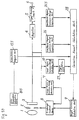
- An image of an object is formed on a pickup element 103 via a lens 101 and a diaphragm 102 .
- the pickup element 103 converts the image into an electric signal.
- the electric signal is subjected to a ⁇ treatment while passing through a signal processing circuit 105 and is output therefrom.
- a diaphragm control is performed by using the electric signal from the pickup element 103 as follows:
- An average value calculation circuit 107 and a peak value calculation circuit 108 respectively detect an average luminance and a peak luminance of an image frame.
- a diaphragm control circuit 109 drives the diaphragm 102 based on the results obtained from the average value calculation circuit 107 and the peak value calculation circuit 108 .
- the average of a luminance distribution of the human figure is lower than the average luminance of the entire image frame. Accordingly, the video signal which corresponds to the human figure occupies a lower part of a distribution of the video signal corresponding to the image frame, resulting in a black reproduced image of the human figure.
- an image quality in a backlight state can be improved by correcting the diaphragm in an opening direction so as to keep the video signals corresponding to the image of the object at a higher level.
- the following method has been considered to provide a diaphragm control at a predetermined control amount:
- An input switching which is manually switched by a user is provided with the diaphragm drive circuit 109 .
- the input switch supplies a switch signal to the diaphragm control circuit 109 .
- Japanese Laid-Open Patent Publication No. 2-18578 discloses an automatic diaphragm apparatus.
- a luminance of the region where the object is supposed to be present e.g. a central portion of an image frame
- a luminance of the remaining portion of the image frame are measured. Based on the difference between these luminances, it is judged whether the object is under a backlight condition or not.
- the correction of the diaphragm control is made according to the backlight condition.
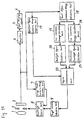
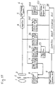
- First and second detectors 113 and 114 detect the level of each output signal having data with respect to a first region (central region of an image frame) and a second region (peripheral region thereof) (see Figure 64 ), output from the pickup element.
- the signals output from the first and second detectors 113 and 114 enter a comparator 123 through amplifiers 121 and 122 .
- the levels of the first and second regions are compared with each other in order to determine the degree of backlight.
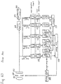
- a first gate portion 110 , a second gate portion 111 , and a third gate portion 112 detect the level of each output signal having data with respect to regions t1 , t2 , and t3 as shown in Figure 65 .
- the respective output signals pass through gain control units 115 , 117 , and 119 so as to be integrated at an adding unit 124 .
- the amplification degree of the first, second, and third gain control units 115 , 117 , and 119 are regulated by a first, second, and third control units 116 , 118 , and 120 which receive information with respect to the determined degree of backlight from the comparator 123 .
- a diaphragm control circuit 109 performs a diaphragm control so as to keep the output signal from the adding unit 124 at a predetermined level.
- the comparator 123 determines that it is in a frontlight state.
- the first, second, and third control units 116 , 118 , and 120 set gains G1, G2, and G3 in the gain control units 115 , 117 , and 119 as G1>G2>G3.
- G1 is slightly larger than G2 and G3.
- the comparator 123 determines that it is in a backlight state.
- the first, second, third control units 116 , 118 , and 120 set the gains G1, G2, and G3 as G1>>G2>G3.
- G1 is remarkably larger than G2 and G3. This means that the gain of the first region is larger than that of the second region, and therefore the luminance of the first region is measured with emphasis. As a result, it is possible to perform a diaphragm control suitable for the backlight condition.
- the output levels of the respective central region and the peripheral region are averaged, even though an image with high contrast is input in an image frame. Therefore, the actual contrast cannot be measured. Namely, the output levels of the central region and the peripheral region change depending on the difference of the spatial distribution of an image luminance; as a result, most video signals are saturated due to overcorrection, or an image which is desired to be further corrected cannot be done so appropriately.
- the exposure correction amount may change in accordance with the movement of an object.
- the automatic exposure control apparatus of this invention includes a image frame luminance calculation unit for calculating an average luminance of an image frame; a region luminance calculation unit for calculating average luminances of a plurality of regions, the plurality of regions constituting the image frame; a select region luminance calculation unit for arranging the average luminances obtained by the region luminance calculation unit in the luminance order, for selecting at least one of the plurality of regions according to the luminance order, and for calculating an average luminance of the selected at least one of the plurality of regions; a backlight degree calculation unit for calculating a value representing a backlight degree based on the average luminance obtained by the select region luminance calculation unit; a target luminance for an exposure correction calculation unit for calculating a target average luminance based on the value; and an exposure correction unit for correcting an exposure so that the average luminance obtained by the image frame luminance calculation unit is kept substantially equal to the target average luminance.
- an automatic exposure control apparatus includes a state judgment unit for judging whether an image frame is in a backlight state or in an excessive frontlight state; an image frame luminance calculation unit for calculating an average luminance of the image frame; a region luminance calculation unit for calculating average luminances of a plurality of regions, the plurality of regions constituting the image frame; a first select region luminance calculation unit for arranging the average luminances obtained by the region luminance calculation unit in the luminance order, for selecting at least one of the plurality of regions according to the luminance order, and for calculating an average luminance of those selected from at least one of the plurality of regions; a second select region luminance calculation unit for arranging the average luminances obtained by the region luminance calculation unit in the luminance order, for selecting at least another one of the plurality of regions according to the luminance order, and for calculating an average luminance of the selected at least another one of the plurality of regions; a backlight degree calculation unit for calculating the first value representing a backlight degree
- an image frame is divided into a plurality of small regions.
- An average luminance of each small region is obtained, and an average value of low luminance regions is calculated, whereby the degree of backlight under an automatic exposure control is quantitatively obtained.
- the judgment between the backlight and the excessive frontlight is made by comparing luminance of the upper region with that of the lower region, and a correction amount of the diaphragm is adjusted.
- the control level of the diaphragm is appropriately changed in accordance with the lighting condition on the basis of the correction amount of the diaphragm.
- the invention described herein makes possible the advantage of providing an automatic exposure control apparatus which is capable of judging a lighting condition of an object and determining the appropriate exposure for the object.
- Figure 1 is a block diagram showing an automatic exposure control apparatus of Example 1 according to the present invention.
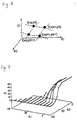
- Figure 2 shows an image frame divided into small regions.
- Figure 3 is a graph showing a luminance order characteristic curve.
- Figures 4A through 4C show backlight images; and Figures 4D through 4F are graphs showing luminance order characteristic curves of the respective backlight images.
- Figure 5 is a block diagram showing an automatic exposure control apparatus of Example 2 according to the present invention.
- Figure 6 is a graph showing a luminance characteristic curve.
- Figure 7 is a view illustrating a linear multiple function.
- Figure 8 is another view illustrating a linear multiple function.
- Figure 9 is still another view illustrating a linear multiple function.
- Figure 10 is a block diagram showing an automatic exposure control apparatus of Example 3 according to the present invention.
- Figures 11A and 11B show an image frame divided into two regions and that divided into small regions.
- Figure 12 is a graph showing a luminance order characteristic curve.
- Figure 13 is a view illustrating backlight and excessive frontlight based on a luminance ratio between the upper and lower regions of an image frame.
- Figure 14 is a block diagram showing an automatic exposure control apparatus of Example 4 according to the present invention.
- Figure 15A shows an excessive frontlight image in which an object is present at a central position D of an image frame together with luminance at each position.
- Figure 15B shows an excessive frontlight image in which an object is present at a top end position T of the image frame together with luminance at each position.
- Figure 15C shows changes of an average luminance of the upper and lower regions while the object moves from the central position D to the top end position T .
- Figure 16 is a block diagram showing an automatic exposure control apparatus of Example 5 according to the present invention.
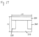
- Figure 17 shows an image frame divided into an upper region, a right region, a left region, and a lower central region.
- Figure 18A shows an excessive frontlight image in which an object is present at a central position D of an image frame together with luminance at each position.
- Figure 18B shows an excessive frontlight image in which an object is present at a top end position T of the image frame together with luminance at each position.
- Figure 18C is a graph showing changes of an average luminance of the first and second regions while the object moves from the central position D to the top end position T .
- Figure 19A is a backlight image in which an object is present at a central position C together with luminance at each position.
- Figure 19B is a backlight image in which the object moves from a right position R to a left position L together with luminance at each position.
- Figure 19C is a graph showing changes of an average luminance of the first and second regions while the object moves the right position R to the left position L .
- Figure 20A shows a backlight image in which an object is present on the right side of an image frame together with luminance at each position.
- Figure 20B shows a backlight image in which the object is present on the right side of the image frame and a dark substance is present on the left side thereof together with luminance at each position.
- Figure 20C is a graph showing changes of an average luminance of the first and second regions while the object is present on the right side of the image frame and the dark substance moves from the left side of the image frame to a boundary position L thereof.
- Figure 20D is a graph showing changes of an average luminance of the first and second regions while the object is present on the right side of the image frame and the dark substance moves from the left side of the image frame to the boundary position L thereof.
- Figure 21 is a block diagram showing an automatic exposure control apparatus of Example 6 according to the present invention.
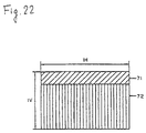
- Figure 22 shows an image frame divided into an upper region and a lower region.
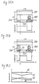
- Figure 23A shows an excessive frontlight image in which an object is present at a central position D of an image frame together with luminance at each position.
- Figure 23B shows an excessive frontlight image in which an object is present at the top end position T of the image frame together with luminance at each position.
- Figure 23C is a graph showing changes of an average luminance of the first and second regions, and the upper and lower regions while the object moves from the central position D to the top end position T .
- Figure 24A shows a backlight image in which an object is present at a central position C of an image frame together with luminance of each position.
- Figure 24B shows a backlight image in which an object moves from a right position R of an image frame to a left position L thereof together with luminance of each position.
- Figure 24C is a graph showing changes of an average luminance of the first and second regions, and the upper and lower regions while the object moves the right position R to the left position L .
- Figure 25A shows a backlight image in which an object is present on the right side of an image frame together with luminance at each position.
- Figure 25B shows a backlight image in which the object is present on the right side of the image frame and a dark substance is present on the left side thereof together with luminance at each position.
- Figure 25C is a graph showing changes of an average luminance of the first and second regions, and upper and lower regions while the object is present on the right side of the image frame and the dark substance moves from the left side of the image frame to a boundary position L thereof.
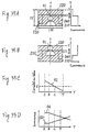
- Figure 26A shows an excessive frontlight image in which an object is present on the right side of an image frame together with luminance at each position.
- Figure 26B shows an excessive frontlight image in which the object is present on the right side of the image frame and a bright substance is present in the left side thereof.
- Figure 26C is a graph showing changes of an average luminance of the first and second regions, and the upper and lower regions while the object is present on the right side of the image frame and the bright substance moves from the left side of the image frame to a boundary position L thereof.
- Figure 27A shows an excessive frontlight image divided into a bright area and a dark area together with luminance at each position.
- Figure 27B is a graph showing the relationship between the luminance and the respective regions of Figure 27A .
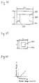
- Figure 28 is an image frame divided into an upper region, a right region, a left region, and a lower central region.
- Figure 29 is a block diagram showing an automatic exposure control apparatus of Example 7 according to the present invention.
- Figure 30 is a diagram illustrating the position of each small region of an image frame.
- Figures 31A and 31B show an average luminance of each small region when the same image in which the central region is bright is taken under different diaphragm states.
- Figures 32A and 32B show an average luminance of each small region by using two values, when the same image in which the central region is bright is taken under different diaphragm states. (An average luminance of each small region is represented by using two values, based on an average luminance of an image frame as a threshold value.)
- Figure 33 is a diagram showing a predetermined luminance distribution.
- Figures 34A and 34B are diagrams showing the respective luminance distributions in image frames having a bright central region.
- Figure 35A shows an excessive frontlight image in which an object is present at a central position D of an image frame together with luminance at each position.
- Figure 35B shows an excessive frontlight image in which the object is present at the top end position T of the image frame together with luminance at each position.
- Figures 35C is a graph showing the correlation value while the object moves from the central position D to the top end position T as shown in Figures 35A and 35B .
- Figure 35D is a graph showing changes of an average luminance of the first and second regions while the object moves from the central position D to the top end position T as shown in Figures 35A and 35B .
- Figure 36A shows a backlight image in which an object is present at a central position C together with luminance at each position.
- Figure 36B shows a backlight image in which an object moves from a right position R of the image frame to a left position L thereof together with luminance at each position.
- Figure 36C is a graph showing a change of a correlation value while the object moves from the right position R to the left position L .
- Figure 36D is a graph showing changes of an average luminance of the first and second regions while the object moves the right position R to the left position L .
- Figure 37 is a block diagram showing an automatic exposure control apparatus of Example 8 according to the present invention.
- Figure 38 shows an image frame divided into an upper region, a right region, a left region, and a lower central region.
- Figure 39 is an image frame divided into a central region and a peripheral region.
- Figure 40 is a graph showing the relationship between the correction amount (of the difference of an average luminance between the first and second regions) and the difference q of an average luminance (between the central region and the image frame).
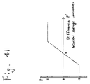
- Figure 41 is a graph showing the conversion from the luminance difference p' obtained by correcting the difference of an average luminance between the first and second regions with the correction amount into the correction amount calculation gain g.
- Figure 42A is an excessive frontlight image in which the central area is bright and the area excluding the central area is dark.
- Figure 42B is a diagram showing the luminance of each region shown in Figure 42A .
- Figure 43A shows an excessive frontlight image in which an object is present at a central position D of an image frame together with luminance at each position.
- Figure 43B shows an excessive frontlight image in which an object is present at a top end position T of the image frame together with luminance at each position.
- Figure 43C shows changes of an average luminance of the central region, an average luminance of the image frame, and a correction amount while the object moves from the central position D to the top end position T as shown in Figures 43A and 43B .
- Figure 43D shows changes of an average luminance of the first region, an average luminance of the second region, and a corrected average luminance of the first region while the object moves from the central region D to the top end T .
- Figure 44A shows a backlight image in which an object is present at a central position C of an image frame together with luminance at each position.
- Figure 44B shows a backlight image in which an object moves from a right position R of the image frame to a left position L thereof together with luminance of each position.
- Figure 44C shows changes of an average luminance of the central region, an average luminance of the image frame, and a correction amount while the object moves the right position R to the left position L as shown in Figures 44A and 44B .
- Figure 44D shows changes of an average luminance of the first region, an average luminance of the second region, and a corrected average luminance of the first region while the object moves from the right position R to the left position L as shown in Figures 44A and 44B .
- Figure 45A is an excessive frontlight image in which the right half area is bright and the left half area is dark.
- Figure 45B is a diagram showing luminance of each region shown in Figure 45A .
- Figure 46 is a block diagram showing an automatic exposure control apparatus of Example 9 according to the present invention.
- Figure 47 is an image frame divided into an upper region, a right region, a left region, and a lower central region.
- Figure 48 is an image frame divided into an upper region, a right region, a left region, and a lower central region.
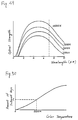
- Figure 49 is a graph showing an spectral distribution of an optical source having a color temperature in the range of 3000 K to 10000 K.
- Figure 50 is a graph showing the relationship between the amount of infrared rays and the color temperature.
- Figure 51 is a graph showing the conversion from the difference p1 of an average luminance between the first and second regions or the difference p2 of an average luminance between the third and forth regions into the correction amount calculation gain g.
- Figure 52 is a block diagram showing an automatic exposure control apparatus of Example 10 according to the present invention.
- Figure 53 is a block diagram showing an automatic exposure control, apparatus of Example 11 according to the present invention.
- Figure 54 is a graph showing the sensitivity of a three primary color filter.
- Figure 55 is block diagram showing an automatic exposure control apparatus of Example 12 according to the present invention.
- Figure 56 is a graph showing the relationship between the color difference and the color temperature.
- Figure 57 is a block diagram showing an automatic exposure control apparatus of Examples 13 to 15 according to the present invention.
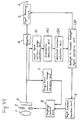
- Figure 58 is a block diagram showing an automatic exposure control apparatus of Example 16 according to the present invention.
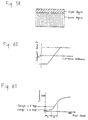
- Figure 59 is an image frame divided into upper and lower regions.
- Figure 60 is a graph illustrating the judgment between the backlight and the excessive frontlight, based on the luminance difference.
- Figure 61 is a luminance order characteristic curve.
- Figure 62 is a block diagram showing a conventional automatic exposure control apparatus.
- Figure 63 is a block diagram showing a conventional automatic exposure control apparatus.
- Figure 64 is an image frame divided into a two regions for illustrating the conventional automatic exposure control apparatus.
- Figure 65 is an image frame divided into three regions for illustrating the conventional automatic exposure control apparatus.
- Figure 1 shows an example of an automatic exposure control apparatus according to the present invention.
- An image of an object is formed on a pickup element 3 through a lens 1 and a diaphragm 2 , and is converted into an electric signal.
- the signal is amplified by an amplifier 4 .
- the signal is subjected to a ⁇ treatment while passing through a signal processing circuit 5 and is transmitted to a video signal output terminal 6 .
- a diaphragm control is performed based on the signal obtained from the pickup element 3 as follows:
- An image frame luminance average calculation unit 7 calculates an average luminance Yall of an image frame, based on the signal from the pickup element 3 .
- a diaphragm control unit 8 compares the average luminance Yall with a target luminance value Yall' obtained by a target luminance calculation unit 9 , and controls the diaphragm opening or closing so that the difference between the average luminance Yall and the target luminance Yall' is made 0, whereby the average luminance Yall is kept substantially equal to the target luminance Yall'. For example, when a dynamic range of the pickup element 3 is 0 to 255 (8-bit information), the target luminance Yall' is set at 127 (central value) in an ordinary exposure control.
- An image frame is divided into a plurality of small regions.
- the image frame 13 is divided into 100 small regions 14 (10 divisions in a vertical direction and 10 divisions in a horizontal direction) as in Figure 2 .
- the average luminance of a small region is represented by an average luminance of pixels included in the small region.
- the apparent number of pixels is 100.
- a small region luminance average calculation unit 10 calculates the average luminance for each small region based on the signal from the pickup element 3 .
- a low luminance average calculation unit 11 arranges an average luminance of each small region in a luminance order as shown in Figure 3 .
- This is called a luminance order characteristic.
- a vertical axis represents luminance and a horizontal axis represents the numbering of each small region (pixel number) arranged in order of low luminance.
- the luminance shows a monotone increase characteristic.
- An average value of low luminance regions (i.e., an average luminance in certain pixel ranges, e.g., pixel number 1 to N) as shown in Figure 3 is a parameter representing the degree of backlight. The principle of this will be described.
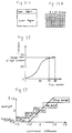
- FIGS. 4A through 4F are examples showing the degree of backlight.
- a shaded portion corresponds to a dark region.
- a region with a luminance of 0 occupies half of an image frame, and the remaining region has a luminance of 255.
- an average luminance becomes 127.
- a luminance order characteristic is as shown in Figure 4D .
- Figure 4B shows an image under a weak backlight state, in which a quarter of an image frame is dark.
- An average value of low luminance regions (an average luminance of regions whose pixel numbers are 1 to 30) is larger than that of Figure 4A .
- an average value of low luminance regions is 0.
- Figure 4C shows an image in a frontlight state.
- An average value of low luminance regions in Figure 4F is larger than that of Figure 4E .
- the degree of backlight which a human being feels can be represented by an average value of low luminance regions. More specifically, as an average value of low luminance regions is smaller, higher degree of backlight is obtained.
- An average value of low luminance regions is obtained by calculating an average value from the lowest luminance (luminance at the 1st pixel) to luminance at the Nth pixel, using the following Formula (1).
- the numbering of pixels is arranged in the order of the lowest luminance to the highest luminance.
- V is an average value of low luminance regions
- v(i) is a luminance level at the ith pixel
- N is a pixel number.
- a backlight degree calculation unit 12 calculates the degree of backlight by applying a gain to the average value of low luminance regions V, using the following Formula (2).
- the diaphragm control unit 8 regulates the diaphragm so that the average luminance Yall is kept at the target luminance Yall'.
- u has a value of 0 or more and the target luminance Yall' becomes high.
- the diaphragm is opened so that the person can become easy to observe a region having too low luminance to be observed.
- the degree of backlight is determined based on an average value of low luminance regions, whereby a stable backlight correction suitable for a human being's feeling can be performed.
- FIG. 5 is a second example of an automatic exposure control apparatus according to the present invention.
- the same reference numerals as those of Example 1 are marked for the same components as those of Example 1.
- the same components as those of Example 1 function in the same way as in Example 1.
- the difference between Example 1 and Example 2 is in that a low luminance average calculation unit 15 and a backlight degree calculation unit 16 are provided in Example 2 instead of the low luminance average calculation unit 11 and the backlight degree calculation unit 12 in Example 1.
- the low luminance average calculation unit 15 calculates a plurality of overage values of low luminance regions in the same way as the low luminance average calculation unit 11 of Example 1.
- Average values in ranges ( a ) and ( b ) are e1 and e2 , respectively.
- the degree of backlight is obtained by using the average values e1 and e2 .
- an average luminance of dark regions can be made a characteristic amount for calculating the degree of backlight by using a plurality of average values of low luminance regions. More specifically, when both of the average values e1 and e2 are low, an exposure control for strong backlight is performed; and only when the average value e1 is low, an exposure control for weak backlight is performed.
- a control rule of simplified fuzzy inference is represented, for example, as follows: If e1 is PB and e2 is NS, then u is f i . where positive big (PB) and negative small (NS) are fuzzy variables; and f i is a real number.
- the final degree of backlight u r obtained by integrating the results of the Formula (4) is as follows: Ichibashi et al. have already reported that the above-mentioned simplified fuzzy inference becomes a linear multiple function (Ichibashi et al., "Learning Control by Fuzzy Models Using a Simplified Fuzzy Reasoning", Nippon fuzzy society report, Vol. 2, No. 3, pp. 429-437). A method of inference based on the linear multiple function is suitable for a real time control due to its low cost of calculation.
- the degree of backlight is obtained by inserting the real number f i .
- Figure 7 shows four points on an input space ( e1 , e2 ) and a real number for each point.
- the real number f i is represented by f ( x p , y q ).
- the degree of backlight u r suitable for various images can be obtained as a non-linear amount by successively determining a real number f ( x p , y q ) from an image under a backlight state.
- Figure 9 shows an example in which the degree of backlight is represented by the linear multiple function. When both of e1 and e2 become low values, the degree of backlight is increased in a non-linear manner.
- a plurality of average values of low luminance regions are obtained, and degrees of backlight are integrated by the fuzzy inference or the linear multiple function, whereby a stable backlight correction suitable for a human being's feeling can be performed.
- Figure 10 is a third example of an automatic exposure control apparatus according to the present invention.
- the same reference numerals as those of Example 1 are marked for the same components as those of Example 1.
- the same components as those of Example 1 function in the same way as in Example 1.
- the image frame luminance average calculation unit 7 calculates an average luminance Yall of an image frame, based on the signal from the pickup element 3 .
- the diaphragm control unit 8 compares the average luminance Yall with a target luminance Yall' obtained by the target luminance calculation unit 9 , and controls the diaphragm to be opened or closed so that the difference between the average luminance Yall and the target luminance Yall' is made 0, whereby the average luminance Yall is kept substantially equal to the target luminance Yall'.
- the target luminance Yall' is set at 127 (central value) in the ordinary exposure control.
- An image frame is divided into an upper region and a lower region as shown in Figure 11A .
- An upper/lower regions luminance average comparison unit 17 calculates an average luminance of the upper and lower regions of the image frame, based on a signal from the pickup element 3 .
- the image frame is also divided into a plurality of small regions.
- the image frame is divided into 80 small regions (8 divisions in a vertical direction and 10 divisions in a horizontal direction) as shown in Figure 11B .
- a small region luminance average calculation unit 18 calculates an average luminance of each small region of the image frame.
- the luminance of a small region is represented by an average luminance of pixels included in the small region.
- the apparent number of pixels is 80.
- the degree of backlight is obtained in the same way as in Example 2.
- a low luminance average calculation unit 19 arranges each average luminance of each small region in the order of low luminance as shown in Figure 6 , and calculates an average value of low luminance regions.
- a backlight degree calculating unit 20 calculates a backlight degree u r by fuzzy inference or a linear multiple function.
- a high luminance average calculation unit 21 calculates an average value from the Mth pixel to the highest luminance.
- e3 is an average value of high luminance regions
- v(i) is a luminance level of the ith pixel from the lowest luminance level
- M is a pixel number.
- An excessive frontlight degree calculation unit 22 calculates an excessive frontlight degree w r by converting e3 by the use of a linear multiple function and the like.
- a degree determination unit 23 determines a final correction amount, based on the backlight degree u r and the excessive frontlight degree w r .
- the degree determination unit 23 judges whether the image frame is in a backlight state or in an excessive frontlight state, based on a luminance difference between the upper region and the lower region of an image frame. Specifically, the degree determination unit 23 calculates the luminance difference by the following Formula (9), and converts the luminance difference into a real value g within an interval [-1, 1].
- Figure 13 shows a conversion diagram from the luminance difference to the real value g.
- Luminance difference (Average luminance of upper re gion) - (Average luminance of lower region) (9)
- a correction amount z is obtained by the following Formula (10).
- the luminance difference between the upper and lower regions is changed. Therefore, even though the luminance difference between the upper and lower regions is changed, an image which is hardly seen cannot be obtained. Thus, the luminance difference between the upper and lower regions can be used to judge whether the image frame is in a backlight state or in an excessive frontlight state.
- the diaphragm control unit 8 regulates a diaphragm so that the average luminance Yall is kept at the above-mentioned target luminance Yall'.
- the image frame is judged to be in a backlight state. Then, a correction is made based on the degree of backlight.
- the image frame is judged to be in an excessive frontlight state. Then, a correction is made based on the degree of excessive frontlight.
- the degree of backlight is obtained based on an average value of low luminance regions and the degree of excessive frontlight is obtained based on an average value of high luminance regions.
- Each degree is selectively regulated in accordance with results obtained by comparing the average luminance of the upper region with that of the lower region, whereby a stable correction suitable for a human being's feeling can be performed.
- the judgment whether it is in a backlight state or in a excessive frontlight state is made based on the luminance difference. It is apparent that the same effects can be obtained even if the ratio between the average luminance of the upper region and the average luminance of the lower region is used instead of the luminance difference.
- Figure 14 shows a forth example of an automatic exposure control apparatus according to the present invention.
- the reference numerals of Example 4 are marked for the same components as those of Example 3.
- the same components as those of Example 4 function in the same way as in Example 3.
- the difference between Examples 3 and 4 is in the functions of the high luminance average calculation unit 21 and the excessive frontlight degree calculation unit 22 .
- a low luminance average calculation unit 24 and an excessive frontlight degree calculation unit 25 are provided instead of the high luminance average calculation unit 21 and the excessive frontlight degree calculation unit 22 .
- the excessive frontlight degree is obtained in the same way as in the backlight degree.
- the low luminance average calculation unit 19 arranges respective average luminances of each small region in the increasing order of the low luminance as shown in Figure 6 , and calculates an average value of low luminance regions.
- an excessive frontlight degree calculation unit 25 calculates the degree of excessive frontlight by the use of fuzzy inference or a linear multiple function.
- the degree determination unit 23 determines a final correction amount based on the backlight degree and the excessive frontlight degree.
- the degrees of backlight and excessive frontlight are obtained based on an average value of low luminance regions.
- Bach degree is selectively regulated in accordance with results obtained by comparing the average luminance of the upper region with that of the lower region, whereby a stable correction suitable for a human being's feeling can be performed.
- the judgment as to whether it is in a backlight state or in a excessive frontlight state is made based on the luminance difference. It is apparent that the same effects can be obtained even if the ratio between the average luminance of the upper region and the average luminance of the lower region is used instead of the luminance difference.
- the present example has an additional objective of preventing a misjudgment with respect to an excessive frontlight image where an object moves up and down.
- Figures 15A and 15B there has been a problem in that the misjudgment mentioned above causes the saturation of the luminance of the object, resulting in forming a white image of the object.
- Figures 15A and 15B show excessive frontlight images where an object moves up and down; and
- Figure 15C shows changes of an average luminance 141 of an upper region 71 and an average luminance 142 of a lower region 72 when the object moves up and down.
- the position of the object is represented by a head top 31 thereof.
- Figure 16 is a fifth example of an automatic exposure control apparatus according to the present invention.
- the same reference numerals as those of the previous examples are marked for the same components as those of the preceding ones.
- the same components as those of the preceding examples function in the same way as those of the preceding examples.
- An image of an object is formed on the pickup element 3 through the lens 1 and the diaphragm 2 , and is converted to an electric signal.
- the signal is amplified by the amplifier 4 .
- the signal is subjected to a ⁇ treatment while passing through the signal processing circuit 5 and is transmitted to the video signal output terminal 6 .
- a diaphragm control is performed based on the signal obtained from the pickup element 3 as follows:
- An image frame luminance average calculation unit 7 calculates an average luminance of an image frame, based on the signal from the pickup element 3 .
- the diaphragm control unit 8 compares the average luminance with a target luminance obtained by the target luminance calculation unit 9 , and controls the diaphragm to be opened or closed so that the difference between the average luminance and the target luminance is made 0, whereby the average luminance is kept substantially equal to the target luminance.
- a small region luminance average calculation unit 10 calculates an average luminance in each of a plurality of small regions based on the signal from the pickup element 3 so as to obtain a luminance order characteristic of the luminance levels.
- the degree calculation unit 27 calculates an average value of low luminance regions from the luminance order characteristic.
- the average luminance of low luminance regions is converted into, a non-linear manner by fuzzy inference or the like, whereby a backlight degree u r representing the degree of backlight of a pickup image is calculated.
- an average luminance of high luminance regions is calculated from the luminance order characteristic, and the average luminance is converted in a non-linear manner by fuzzy inference, whereby an excessive frontlight degree w r is calculated.
- the image frame is divided into a lower central region 210 , an upper region 220 , a left region 230 , and right region 240 as shown in Figure 17 .
- a first/second regions luminance average comparison unit 26 calculates an average luminance of each region, and a difference p between an average luminance of the second region and an average luminance of the first region.
- the degrees of backlight and excessive frontlight, and the difference p are transmitted to a correction amount calculation unit 28 .
- the correction amount calculation unit 28 judges the image frame to be in a backlight state in the case where the average luminance of the first region is higher than that of the second region, and judges the image frame to be in an excessive frontlight state in the case where the average luminance of the first region is lower than that of the second region. These judgments are based on the tendency that an image frame is likely to be in a backlight state when an upper region of the image frame is brighter than the lower region thereof, and that the image frame is likely to be in an excessive frontlight state otherwise.
- the correction amount calculation unit 28 converts the luminance difference p into a gain g used for calculating the correction amount z as shown in Figure 13 .
- Figures 18A and 18B show excessive frontlight images in the case where an object moves up and down; and Figure 18C shows changes of an average luminance 32 of the first region and of an average luminance 33 of the second region.
- the position of the object is represented by the head top 311 thereof.
- the average luminance 32 of the first region does not exceed the average luminance 33 of the second region, while the object moves from a central position D to a top end position T .
- a misjudgment is not made with respect to the excessive frontlight image where an object moves up and down, so that neither the gain g nor the correction amount z do not change.
- Figures 19A and 19B show backlight images where an object moves from side to side; and Figure 19C shows changes of an average luminance 32 of the first region and an average luminance 33 of the second region while the object moves from a right position R to a left position L . As shown in Figure 19C , while the object moves from the right position R to the left position L , the average luminance 33 of the second region does not exceed the average luminance 32 of the first region.
- Figures 20A and 20B show backlight images where an object is present on the right side of an image frame and a dark substance gets in and out of the left side thereof; and Figure 20C shows changes of an average luminance 32 of the first region and an average luminance 33 of the second region.
- the position of the substance is represented by a right end 51 thereof.
- an average luminance 33 of the second region does not exceed an average luminance 32 of the first region.
- Figure 20D shows changes of the average luminance 32 of the first region and the average luminance 33 of the second region, with respect to a backlight image where an object is present on the right side of the image frame and a dark substance gets in and out of the left side thereof.
- an image frame is divided so that the sum of the vertical length of the right region and that of the upper region and the sum of the vertical length of the left region and that of the upper region respectively coincide with the vertical length of the image frame.
- the average luminance 32 of the first region exceeds the average luminance 33 of the second region.
- the image frame is divided so that the sum of the vertical length of the right region and that of the upper region and the sum of the vertical length of the left region and that of the upper region are respectively made smaller than the vertical length of the image frame. Therefore, it is required that the image frame is divided so that the sum of the vertical length of the right and that of the upper region and the sum of the left region and that of the upper region are respectively made smaller than the vertical length of the image frame.
- the target luminance calculation unit 9 sets a target value of an average luminance of an image frame for each vertical scanning, by adding the correction amount z obtained by the correction amount calculation unit 28 to a predetermined target luminance.
- the diaphragm control unit 8 regulates a diaphragm so that the average luminance of the image frame is kept substantially equal to the target value.
- the judgment whether it is in a backlight state or in a excessive frontlight state is made based on the luminance difference. It is apparent that the same effects can be obtained even if the ratio between the average luminance of the upper region and the average luminance of the lower region is used instead of the luminance difference.
- Example 5 A sixth example of an automatic exposure control apparatus according to the present invention will be described with reference to Figure 21 .
- the same reference numerals as those of Example 5 are marked for the same components as those of Example 5.
- the same components as those of Example 5 function in the same way as in Example 5.
- An image of an object is formed on the pickup element 3 through the lens 1 and the diaphragm 2 , and is converted to an electric signal.
- the signal is amplified by the amplifier 4 .
- the signal is subjected to a ⁇ treatment while passing through the signal processing circuit 5 and is transmitted to the video signal output terminal 6 .
- a diaphragm control is performed based on the signal obtained from the pickup element 3 as follows:
- An image frame luminance average calculation unit 7 calculates an average luminance of an image frame, based on the signal from the pickup element 3 .
- the diaphragm control unit 8 compares the average luminance with a target luminance value obtained by the target luminance calculation unit 9 , and controls the diaphragm to be opened or closed so that the difference between the average luminance and the target luminance is made 0, whereby the average luminance is kept substantially equal to the target luminance.
- a small region luminance average calculation unit 10 calculates an average luminance in each of a plurality of small regions based on the signal from the pickup element 3 so as to obtain a luminance order characteristic of the luminance levels.
- the degree calculation unit 27 calculates an average value of low luminance regions from the luminance order characteristic.
- the average luminance of low luminance regions is converted in a non-linear manner by fuzzy inference or the like, whereby a backlight degree u r representing the degree of backlight of a pickup image is calculated.
- an average luminance of high luminance regions is calculated from the luminance order characteristic, and the average luminance is converted in a non-linear manner by fuzzy inference, whereby an excessive frontlight degree w r is calculated.
- An image frame is divided into a lower central region 210 , an upper region 220 , a left region 230 , and a right region 240 as shown in Figure 17 .
- the first/second regions luminance average comparison unit 26 calculates an average luminance of each region and a luminance ratio p1 of an average luminance of the second region to that of the first region.
- a first judgment unit 61 judges whether the image frame is in a backlight state or in an excessive frontlight state, based on the luminance ratio p1 obtained by the first/second regions luminance average comparison calculation unit 26 in the same way as in Example 5.
- a second judgment unit 62 divides an image frame into an upper region 71 and a lower region 72 as shown in Figure 22 , and calculates an average luminance ratio p2 therebetween.
- the second judgment unit 62 judges an image frame to be in a backlight state in the case where an average luminance of the upper region 71 is higher than that of the lower region 72 ; and judges the image frame to be in an excessive frontlight state in the case where an average luminance of the upper region 71 is lower than that of the lower region 72 .
- a judgment value j2 is calculated by the following Formula (14).
- a correction amount calculation unit 63 calculates a correction amount z1, based on the backlight degree u r , the excessive frontlight degree w r , the judgment value j1, and the judgment value j2 by the following Formula (15).
- the relationship between the movement of the object and the respective average luminances of the first and second regions, and the upper and lower regions will be described with reference to Figures 23A to 23C , 24A to 24C , 25A to 25C , and 26A to 26C .
- the respective average luminances of the first and second regions are obtained by the first/second regions luminance average comparison unit 26 ; and the respective average luminances of the upper and lower regions are obtained by the second judgment unit 62 .
- Figures 23A and 23B show excessive frontlight images where an object moves up and down; and Figure 23C shows changes of an average luminance 32 of the first region, an average luminance 33 of the second region, an average luminance 81 of the upper region, and an average luminance 82 of the lower region, while the object moves from a central position D to a top end position T .
- the position of the object is represented by a head top 31 thereof.
- the average luminance 32 of the first region does not exceed the average luminance 33 of the second region. Therefore, a misjudgment is not made and a correction amount z1 does not change.
- a correction amount z1 with respect to a backlight image where an object moves from side to side a correction amount z1 with respect to a backlight image where an object is present on the right side of an image frame and a dark substance gets in and out of the left side thereof; a correction amount z1 with respect to a backlight image where an object is present on the right side of the image frame and a bright substance gets in and out of the right side thereof will be described.
- Figures 24A and 24B show backlight images in the case where an object moves from side to side; and Figure 24C shows changes of an average luminance 32 of the first region, an average luminance 33 of the second region, an average luminance 81 of the upper region, and an average luminance 82 of the lower region, while the object moves from a right position R to a left position L .
- the position of the object is represented by a head top 31 thereof.
- the average luminance 32 of the first region and the average luminance 33 of the second region do not change. Therefore, the correction amount z1 does not change.
- Figures 25A and 25B show backlight images in the case where an object is present on the right side of an image frame and a dark substance gets in and out of the left side thereof; and Figure 25C shows changes of an average luminance 32 of the first region, an average luminance 33 of the second region, an average luminance 81 of the upper region, and an average luminance 82 of the lower region.
- the position of the substance is represented by a right end 51 thereof.
- Figures 26A and 26B show excessive frontlight images in the case where an object is present on the right side of the image frame and a bright substance gets in and out of the left side thereof; and Figure 26C shows changes of an average luminance 32 of the first region, an average luminance 33 of the second region, an average luminance 81 of the upper region, and an average luminance 82 of the lower region.
- the position of the substance is represented by a right end 121 thereof.
- the average luminance 81 of the upper region does not exceed the average luminance 82 of the lower region.
- the correction amount z1 does not change.
- the target luminance calculation unit 9 sets a target value of an average luminance of an image frame for each vertical scanning (frame or field), by adding the correction amount z1 obtained by the correction amount calculation unit 63 to a predetermined target luminance.
- the diaphragm control unit 8 regulates a diaphragm so that the average luminance of the image frame is kept substantially equal to the target value.
- an appropriate exposure of an object for an excessive frontlight image where the object moves up and down, a backlight image where the object moves from side to side, a backlight image where a dark substance gets in and out of one side of the image frame, and a backlight image where a bright substance gets in and out of both sides of the image frame can be obtained.
- the judgment is made as to whether it is in a backlight state or in an excessive frontlight state is based on the luminance ratio. It is apparent that the same effects can be obtained even if the difference between the average luminance of the upper region and the average luminance of the lower region is used instead of the luminance ratio.
- a seventh example of the present invention will be described.
- the present example overcomes the following problem; An excessive frontlight image where a central region of an image frame is bright and a lower region thereof is dark is misjudged to be in a backlight state and the luminance of a main object is saturated so as to become white. This phenomenon is often caused in the case where an outdoor scene is taken from an indoor side.
- Figure 27A shows an excessive frontlight image where a central region of an image frame is bright and the remaining region thereof is dark; and Figure 27B shows an average luminance of a lower central region 210 , an upper region 220 , a left region 230 , a right region 240 , a first region and a second region, obtained by dividing the image frame as shown in Figure 28 .
- the first region corresponds to a combination of the left or right region which has a higher luminance and the upper region; and the second region corresponds to a combination of the left or right region which has a lower luminance and the lower region.
- the present example is one embodiment for overcoming this problem. Its objective is to provide an automatic exposure control apparatus which does not misjudge an excessive frontlight image where a central region of an image frame is bright and the remaining region thereof is dark. In addition, the apparatus also does not misjudge a backlight image where an object moves from side to side and an excessive frontlight image where an object moves up and down.
- Figure 29 shows a seventh example of an automatic exposure control apparatus according to the present invention.
- the same reference numerals as those of the preceding examples are marked for the same components as those of the preceding examples.
- the same components as those of the preceding examples function in the same way as in the preceding examples.
- An image of an object is formed on the pickup element 3 through the lens 1 and the diaphragm 2 , and is converted to an electric signal.
- the signal is amplified by the amplifier 4 .
- the signal is subjected to a ⁇ treatment while passing through the signal processing circuit 5 and is transmitted to the video signal output terminal 6 .
- a diaphragm control is conducted based on the signal obtained from the pickup element 3 as follows:
- An image frame luminance average calculation unit 7 calculates an average luminance of an image frame, based on the signal from the pickup element 3 .
- the diaphragm control unit 8 compares the average luminance with a target luminance obtained by the target luminance calculation unit 9 , and controls the diaphragm to be opened or closed so that the average luminance is kept substantially equal to the target luminance.
- a small region luminance average calculation unit 10 calculates an average luminance in each of a plurality of small regions based on the signal from the pickup element 3 so as to obtain a luminance order characteristic of the luminance levels.
- the degree calculation unit 27 calculates an average value of low luminance regions from the luminance order characteristic.
- the average luminance of low luminance regions is converted in a non-linear manner by fuzzy inference or the like, whereby a backlight degree u r representing the degree of backlight of a pickup image is calculated.
- an average luminance of high luminance regions is calculated from the luminance order characteristic, and the average luminance is converted in a non-linear manner by fuzzy inference, whereby an excessive frontlight degree w r is calculated.
- An image frame is divided into the lower central region 210 , the upper region 220 , the left region 230 , and the right region 240 as shown in Figure 28 .
- the first/second regions luminance average comparison unit 26 calculates an average luminance of each region and a difference p of an average luminance between the first region and the second region.
- a correlation value calculation unit 29 calculates a correlation value E, based on an average luminance S ij and a predetermined luminance distribution V ij of an excessive frontlight image where a predetermined central region is bright, using the following Formula (16).
- the S ij represents an average luminance of each small region of the image frame, which is normalized with an average luminance of the image frame.
- the V ij represents a predetermined luminance of each small region of the image frame.
- the i and j of the V ij and V ij represent a position of a small region in the image frame as shown in Figure 30 .
- the normalization of an average luminance of each small region performed by the correlation value calculation unit 29 and the predetermined luminance distribution will be described in detail with reference to Figures 31A , 31B , 32A , 32B , 33 , 34A and 34B .
- Figures 31A and 31B show an average luminance of each small region and an average luminance of an image frame in a case where a bright object positioned at a central region of the image frame is in an excessive frontlight state, but the bright object is taken with different diaphragm values.
- the image frame includes 25 small regions.
- the image frames of Figures 31A and 31B are in the same excessive frontlight state. Accordingly, these image frames should have the same correlation values. However, if the correlation values corresponding to the image frames of Figures 31A and 31B were calculated based on average luminances of small regions, the calculated correlation values would all be different from each other. This is because a predetermined luminance distribution used for calculating the correlation value is fixed, and the average luminance of each small region of the image frame of Figure 31A is different from that of Figure 31B when the object is taken with different diaphragm values.
- the average luminance of each small region of the image frame of Figure 31A is normalized with an average luminance of the image frame, which will be described below.
- the average luminances of each small region of Figure 31A and that of Figure 31B are compared with an average luminance of an image frame.
- the average luminance of a small region is made 1; and when an average luminance of a small region is smaller than the average luminance of the image frame, the average luminance of the small region is made to be 0.
- the resuits are shown in Figures 32A and 32B , respectively.
- the replacement of the average luminance of each small region into two values (either 0 or 1) by using the average luminance of the image frame as a threshold value causes the same luminance distribution even though the object is taken with different diaphragm values.
- Figure 33 shows a predetermined luminance distribution of an excessive frontlight image where a predetermined central region is bright. The reason why a vertical length of the predetermined luminance distribution is made smaller than that of an image frame is to distinguish an excessive frontlight image of Figure 34A from another excessive frontlight image of Figure 34B .
- the degrees of backlight and excessive frontlight, the average luminance difference, and the correlation value E are transmitted to the correction amount calculation unit 28 .
- the correction amount calculation unit 28 compares the correlation value E with a threshold value ⁇ .
- the correlation value E is smaller than the threshold value ⁇ , the image frame is judged to be in an excessive frontlight state, where a central region is bright, and the correction amount z is made the excessive frontlight degree w r .
- the correlation value E is larger than the threshold value ⁇ , the following judgments are made using the average luminance difference p: In the case where an average luminance of the first region is higher than that of the second region, the image frame is judged to be in a backlight state, and in the case where an average luminance of the first region is lower than that of the second region, the image frame is judged to be in an excessive frontlight state.
- the correction amount calculation unit 28 converts the luminance difference p into a gain g used for calculating the correction amount as shown in Figure 13 . Then, the correction amount z is calculated by the following Formula (17), based on the backlight degree u r , the excessive frontlight degree w r , the gain g, and the results of the judgment between the backlight and the excessive frontlight.
- Figures 35A and 35B show excessive frontlight images in the case where an object moves up and down;
- Figure 35C shows a change of a correlation value 92 while the object moves from the central position D of the image frame to the top end position T thereof;
- Figure 35D shows changes of an average luminance 83 of the first region and an average luminance 84 of the second region while the object moves from the central position D to the top end position T .
- the position of the object is represented by the head top 91 thereof.
- the correlation value 92 becomes smaller than the threshold value ⁇ .
- the correlation value 92 is equal to or less than the threshold value ⁇ , the image frame is judged to be in an excessive frontlight state, causing no problems.
- a problem arises when the correlation value 92 is larger than the threshold value ⁇ .
- the average luminance 83 of the first region is smaller than the average luminance 84 of the second region at all times, so that the image frame is judged to be in an excessive frontlight state, making no misjudgments.
- Figures 36A and 36B show backlight images where an object moves from side to side;
- Figure 36C shows a change of a correlation value 92 while the object moves from the right position R to the left position L ;
- Figure 36D shows changes of an average luminance 93 of the first region and an average luminance 94 of the second region, while object moves from the right position R to the left position L .
- the position of the object is represented by a head top 91 thereof.
- the correlation value E is larger than the threshold value ⁇ at all times, so that the image frame is judged to be in a backlight or an excessive frontlight, based on an average luminance difference between the first and second regions.
- the average luminance 93 of the first region is larger than the average luminance 94 of the second region at all times, so that the image frame is judged to be in a backlight state, making no misjudgments.
- the target luminance calculation unit 9 sets a target value of an average luminance of an image frame for each vertical scanning (frame or field), by adding the correction amount z obtained by the correction amount calculation unit 28 to a predetermined target luminance.
- the diaphragm control unit 8 regulates a diaphragm so that the average luminance of the image frame is kept substantially equal to the target value.
- an appropriate exposure of an object for an excessive frontlight image where the central region of the image frame is bright and the remaining region thereof is dark, an excessive frontlight image where an object moves up and down, and a backlight image where an object moves from side to side can be obtained.
- the present example also overcomes the following problem; An excessive frontlight image where a central region of an image frame is bright and a lower region thereof is dark is misjudged to be in a backlight state and the luminance of a main object is saturated to become white. This phenomenon is often caused in the case where an outdoor scene is taken from an indoor site.
- FIG 37 shows an eighth example of an automatic exposure control apparatus according to the present invention.
- the same reference numerals as those of the preceding examples are marked for the same components as those of the preceding examples.
- the same components as those of the preceding examples function in the same way as in the preceding examples.
- An image of an object is formed on the pickup element 3 through the lens 1 and the diaphragm 2 , and is converted to an electric signal.
- the signal is amplified by the amplifier 4 .
- the signal is subjected to a ⁇ treatment while passing through the signal processing circuit 5 and is transmitted to the video signal output terminal 6 .
- a diaphragm control is performed based on the signal obtained from the pickup element 3 as follows:
- An image frame luminance average calculation unit 7 calculates an average luminance of an image frame, based on the signal from the pickup element 3 .
- the diaphragm control unit 8 compares the average luminance with a target luminance obtained by the target luminance calculation unit 9 , and controls the diaphragm to be opened or closed so that the difference between the average luminance and the target luminance is made 0, whereby the average luminance is kept substantially equal to the target luminance.
- a small region luminance average calculation unit 10 calculates an average luminance of each of a plurality of small regions based on the signal from the pickup element 3 so as to a luminance order characteristic of the luminance levels.
- the degree calculation unit 27 calculates an average value of low luminance regions from the luminance order characteristic.
- the average luminance of low luminance regions is converted in a non-linear manner by fuzzy inference or the like, whereby a backlight degree u r representing the degree of backlight of a pickup Image is calculated.
- an average luminance of high luminance regions is calculated from the luminance order characteristic, and the average luminance is converted in a non-linear manner by fuzzy inference, whereby an excessive frontlight degree w r is calculated.
- An image frame is divided into a lower central region 210 , an upper region 220 , a left region 230 , and a right region 240 as shown in Figure 38 .
- the first/second regions luminance average comparison unit 26 calculates an average luminance of each region and a difference p of an average luminance between the first and second regions.
- a comparison result correction unit 30 divides the image frame into a central region 3931 and a peripheral region 3932 as shown in Figure 39 and calculates an average luminance of each region, based on the signal from the pickup element 3 .
- a difference q of an average luminance between the image frame and the central region 3931 i.e., an average luminance of the central region 3931 - an average luminance of the image frame
- the difference q of an average luminance is converted into a correction amount ⁇ for correcting a difference p of an average luminance between the first and second regions as shown in Figure 40 .
- a corrected difference p' of an average luminance is calculated using the difference p of an average luminance and the correction amount ⁇ by the following Formula (18).
- p' p - ⁇ (18)
- the degrees of backlight and excessive frontlight, and the corrected difference p' of an average luminance are transmitted to the correction amount calculation unit 28 .
- the correction amount calculation unit 28 judges the image frame to be in a backlight state in the case where a value obtained by subtracting the correction amount ⁇ from the average luminance of the first region is larger than the average luminance of the second region, and judges the image frame to be in an excessive frontlight state in the case where a value obtained by subtracting the correction amount ⁇ from the average luminance of the first region is smaller than the average luminance of the second region.
- the correction amount calculation unit 28 converts the corrected average luminance difference p' into a gain g used for calculating a correction amount z as shown in Figure 41 . Then, a correction amount z is calculated by the following Formula (19), based on the backlight degree u r , the excessive frontlight degree w r , the gain g, and the result of judgment between the backlight and the excessive frontlight.
- Figure 42A shows an excessive frontlight image where the central region of the image frame is bright and the remaining region thereof is dark; and Figure 42B shows the average luminance of the central region of the image frame in Figure 42A , the average luminance of the image frame, the correction amount ⁇ , the average luminance of the first and second regions, and the value obtained by subtracting the correction amount ⁇ from the average luminance of the first region.
- the value obtained by subtracting the correction amount ⁇ from the average luminance of the first region is smaller than the average luminance of the second region. Because of this, no misjudgments are made with respect to the excessive frontlight image where the central region is bright and the lower region is dark. Thus, nether gain g nor the correction amount z change.
- Figures 43A and 43B show excessive frontlight images where an object moves up and down;
- Figure 43C shows changes of an average luminance 172 of the central region of an image frame, an average luminance 73 of the image frame, and a correction amount 74 ;
- Figure 43D shows changes of an average luminance 75 of the first region, an average luminance 76 of the second region, and a corrected average luminance 77 of the first region.
- the position of the object is represented by a head top 91 thereof.
- Figures 44A and 44B show backlight images in the case where an object moves from side to side;
- Figure 44C shows changes of an average luminance 182 of the central region, an average luminance 183 of an image frame, and a correction amount 184 ;
- Figure 44D shows an average luminance 85 of the first region, an average luminance 86 of the second region, and a corrected average luminance 87 of the first region.
- the position of the object is represented by a head top 91 thereof.
- the target luminance calculation unit 9 sets a target value of an average luminance of an image frame for each vertical scanning (frame or field), by adding the correction amount z obtained by the correction amount calculation unit 28 to a predetermined target luminance.
- the diaphragm control unit 8 regulates a diaphragm so that the average luminance of the image frame is kept substantially equal to the target value.
- an appropriate exposure of an object for an excessive frontlight image where the central region of the image frame is bright and the lower region thereof is dark, an excessive frontlight image where an object moves up and down, and a backlight image where an object moves from side to side can be obtained.
- a ninth example of the present invention will be described.
- the present example overcomes the following problem: When an object is irradiated with a spot light indoors (e.g., a wedding party), an excessive frontlight image where the right half of an image frame is bright and the left half thereof is dark is misjudged to be in a backlight state. As a result, the luminance of the object is saturated so as to become white.
- a spot light indoors e.g., a wedding party
- Figure 45A shows an excessive frontlight image where a right half of an image frame is bright and the left half thereof is dark; and Figure 45B shows an average luminance of each region obtained by dividing the image frame shown in Figure 45A into an upper region, a lower central region, a right region, and a left region as shown in Figure 38 , and an average luminance of the respective first and second regions.
- the first region corresponds to a combination of either one of the right or left regions which has a higher luminance and the upper region; and the second region corresponds to a combination of either one of the right or left regions which has a lower luminance and the lower region.
- the average luminance of the first region is higher than that of the second region, so that the image frame is misjudged to be in a backlight state.
- the present example overcomes the above-mentioned problem, and its objective is to provide an automatic exposure control apparatus which does not make a misjudgment with respect to an excessive frontlight image where indoors; the right half of an image frame is bright and the left half thereof is dark, and does not make a misjudgment with respect to a backlight image where outdoors, the right half of an image frame is bright and the left half thereof is dark.
- Figure 46 shows a ninth example of an automatic exposure control apparatus according to the present invention.
- the same reference numerals as those of the preceding examples are marked for the same components as those of the preceding examples.
- the same components as those of the preceding examples function in the same way as in the preceding examples.
- An image of an object is formed on the pickup element 3 through the lens 1 and the diaphragm 2 , and is converted to an electric signal.
- the signal is amplified by the amplifier 4 .
- the signal is subjected to a ⁇ treatment while passing through the signal processing circuit 5 and is transmitted to the video signal output terminal 6 .
- a diaphragm control is performed based on the signal obtained from the pickup element 3 as follows:
- An image frame luminance average calculation unit 7 calculates an average luminance of an image frame, based on the signal from the pickup element 3 .
- the diaphragm control unit 8 compares the average luminance with a target luminance obtained by the target luminance calculation unit 9 , and controls the diaphragm to be opened or closed so that the difference between the average luminance and the target luminance is made to be 0, whereby the average luminance is kept substantially equal to the target luminance.
- a small region luminance average calculation unit 10 calculates an average luminance in each of a plurality of small regions based on the signal from the pickup element 3 so as to obtain a luminance order characteristic of the luminance levels.
- the degree calculation unit 27 calculates an average value of low luminance regions from the luminance order characteristic.
- the average luminance of low luminance regions is converted in a non-linear manner by fuzzy inference or the like, whereby a backlight degree u r representing the degree of backlight of a pickup image is calculated.
- an average luminance of high luminance regions is calculated from the luminance order characteristic, and the average luminance is converted in a non-linear manner by fuzzy inference, whereby an excessive frontlight degree w r is calculated.
- An image frame is divided into a lower central region 210 , an upper region 220 , a left region 230 , and a right region 240 as shown in Figure 47 .
- the first/second regions luminance average comparison unit 26 calculates an average luminance of each region and a difference p1 of an average luminance between the first region and the second region.
- the image frame is also divided into a lower central region 310 , an upper region 320 , a left region 330 , a right region 340 , as shown in Figure 48 .
- a third/fourth regions luminance average comparison unit 315 calculates an average luminance of each region and a difference p2 of an average luminance between the third and forth regions.
- the infrared rays amount detection unit 140 detects infrared rays from a light source, and converts the detected infrared rays into an electric signal q in proportion to the amount of the detected infrared rays.
- a color temperature of an indoor light source is different from that of an outdoor light source.
- the color temperature of an indoor light source such as a fluorescent light is generally in the range of 3000 to 3500 K; and the color temperature of an outdoor light source such as the sun is 3500 K or more.
- Figure 49 shows a spectral distribution in the case where the color temperature of an light source changes from 3000 K to 10000 K.
- Infrared rays have a wavelength longer than the wavelength represented by a broken line in Figure 49 ; and the amount of infrared rays corresponds to an area which is situated to the right side of the broken line.
- Figure 50 shows the relationship between the color temperature and the amount of infrared rays. As is understood from Figure 50 , the judgment between the indoors and the outdoors is made possible by setting a threshold value ⁇ .
- the difference p1 in an average luminance, the difference p2 in an average luminance, and the control signal r, and the degrees of backlight and excessive frontlight are transmitted to the correction amount calculation unit 28 .
- the correction amount calculation unit 28 selects the difference p1 outdoors and selects the difference p2 indoors, according to the control signal r. These selections are based on the tendency that an image frame having a bright right half and a dark left half is likely to be in an excessive frontlight state indoors and the same image frame is likely to be in a backlight state outdoors.
- the correction amount calculation unit 28 judges an image frame to be in a backlight state when the first or third region containing the upper region has an average luminance higher than that of the second or forth region containing the lower center region; and judges an image frame to be in an excessive frontlight state when the first or third region has an average luminance lower than that of the second or forth region. These judgments are based on the tendency that it is likely to be in a backlight state when the upper region is brighter than the lower region, and it is likely to be in an excessive frontlight state when the upper region is darker than the lower region. Moreover, the correction amount calculation unit 28 converts the difference p1 or the difference p2 into a gain g used for calculating a correction amount as shown in Figure 51 .
- the target luminance calculation unit 9 sets a target value of an average luminance of an image frame for each vertical scanning (frame or field), by adding the correction amount z obtained by the correction amount calculation unit 28 to a predetermined target luminance.
- the diaphragm control unit 8 regulates a diaphragm so that the average luminance of the image frame is kept substantially equal to the target value.
- an appropriate exposure of an object for an excessive frontlight image where the central region of the image frame is bright and the lower region thereof is dark, an excessive frontlight image where an object moves up and down, and a backlight image where an object moves from side to side can be obtained.
- Figure 52 is a tenth example of an automatic exposure control apparatus according to the present invention.
- the present example overcomes the same problem as in Example 9.
- An image of an object is formed on the pickup element 3 through the lens 1 and the diaphragm 2 , and is converted to an electric signal.
- the signal is amplified by the amplifier 4 .
- the signal is subjected to a ⁇ treatment while passing through the signal processing circuit 5 and is transmitted to the video signal output terminal 6 .
- a diaphragm control is performed based on the signal obtained from the pickup element 3 as follows:
- An image frame luminance average calculation unit 7 calculates an average luminance of an image frame, based on the signal from the pickup element 3 .
- the diaphragm control unit 8 compares the average luminance with a target luminance value obtained by the target luminance calculation unit 9 , and controls the diaphragm to be opened or closed so that the difference between the average luminance and the target luminance is made to be 0, whereby the average luminance is kept substantially equal to the target luminance.
- a small region luminance average calculation unit 10 calculates an average luminance in each of a plurality of small regions based on the signal from the pickup element 3 so as to obtain a luminance order characteristic of the luminance levels.
- the degree calculation unit 27 calculates an average value of low luminance regions from the luminance order characteristic.
- the average luminance of low luminance regions is converted in a non-linear manner by fuzzy inference or the like, whereby a backlight degree u r representing the degree of backlight of a pickup image is calculated.
- an average luminance of high luminance regions is calculated from the luminance order characteristic, and the average luminance is converted in a non-linear manner by fuzzy inference, whereby an excessive frontlight degree w r is calculated.
- An image frame is divided into the lower central region 210 , the upper region 220 , the left region 230 , and the right region 240 as shown in Figure 47 .
- the first/second regions luminance average comparison unit 26 calculates an average luminance of each region and a difference p1 of an average luminance between the first region and the second region.
- the image frame is also divided into a lower central region 310 , an upper region 320 , a left region 330 , a right region 340 , as shown in Figure 48 .
- a third/fourth regions luminance average comparison unit 315 calculates an average luminance of each region and a difference p2 of an average luminance between the third and forth regions.
- the amount of light from an outdoor light source such as the sun is larger than the amount of light from an indoor light source such as a fluorescent light.
- the judgment between the indoors and the outdoors is made based on the amount of light which is inferred from the average luminance Yall and the diaphragm value F.
- the difference p1 of an average luminance, the difference p2 of an average luminance, the control signal r, and the degrees of backlight and excessive frontlight are transmitted to the correction amount calculation unit 28 .
- the correction amount calculation unit 28 selects the difference p1 outdoors and selects the difference p2 indoors, according to the control signal r. These selections are based on the tendency that an image frame having a bright right half and a dark left half is likely to be in an excessive frontlight state indoors and the same image frame is likely to be in a backlight state outdoors.
- the correction amount calculation unit 28 judges an image frame to be in a backlight state when the first or third region containing the upper region has an average luminance higher than that of the second or forth region containing the lower central region; and judges an image frame to be in an excessive frontlight state when the first or third region has an average luminance lower than that of the second or forth region. These judgments are based on the tendency that it is likely to be in a backlight state when the upper region is brighter than the lower region, and that it is likely to be in an excessive frontlight state when the upper region is darker than the lower region.
- the correction amount calculation unit 28 converts the difference p1 or the difference p2 into a gain g used for calculating a correction amount as shown in Figure 51 . Then, a correction amount z is calculated by the Formula (21), based on the backlight degree u r , the excessive frontlight degree w r , the gain g, and the result of the judgment between the backlight and the excessive frontlight.
- the target luminance calculation unit 9 sets a target value of an average luminance of an image frame for each vertical scanning (frame or field), by adding the correction amount z obtained by the correction amount calculation unit 28 to a predetermined target luminance.
- the diaphragm control unit 8 regulates a diaphragm so that the average luminance of the image frame is kept substantially equal to the target value.
- an appropriate exposure of an object for an excessive frontlight image where the central region of the image frame is bright and the lower region thereof is dark, an excessive frontlight image where an object moves up and down, and a backlight image where an object moves from side to side can be obtained.
- FIG. 53 shows an eleventh example of an automatic exposure control apparatus according to the present invention.
- An image of an object is formed on the pickup element 3 through the lens 1 and the diaphragm 2, and is converted to an electric signal.
- the signal is amplified by the amplifier 4 .
- the signal is subjected to a ⁇ treatment while passing through the signal processing circuit 5 and is transmitted to the video signal output terminal 6 .
- a diaphragm control is performed based on the signal obtained from the pickup element 3 as follows:
- An image frame luminance average calculation unit 7 calculates an average luminance of an image frame, based on the signal from the pickup element 3 .
- the diaphragm control unit 8 compares the average luminance with a target luminance obtained by the target luminance calculation unit 9 , and controls the diaphragm to be opened or closed so that the difference between the average luminance and the target luminance is made 0, whereby the average luminance is kept substantially equal to the target luminance.
- a small region luminance average calculation unit 10 calculates an average luminance in each of a plurality of small regions based on the signal from the pickup element 3 so as to obtain a luminance order characteristic of the luminance levels.
- the degree calculation unit 27 calculates an average value of low luminance regions from the luminance order characteristic.
- the average luminance of low luminance regions is converted in a non-linear manner by fuzzy inference or the like, whereby a backlight degree u r representing the degree of backlight of a pickup image is calculated.
- an average luminance of high luminance regions is calculated from the luminance order characteristic, and the average luminance is converted in a non-linear manner by fuzzy inference, whereby an excessive frontlight degree w r is calculated.
- An image frame is divided into the lower central region 210 , the upper region 220 , the left region 230 , and the right region 240 as shown in Figure 47 .
- the first/second regions luminance average comparison unit 26 calculates an average luminance of each region and a difference p1 of an average luminance between the first region and the second region.
- the image frame is also divided into a lower central region 310 , an upper region 320 , a left region 330 , a right region 340 , as shown in Figure 48 .
- a third/fourth regions luminance average comparison unit 315 calculates an average luminance of each region and a difference p2 of an average luminance between the third and forth regions.
- a color temperature calculation unit 815 detects lights from an light source through a primary color (red, blue and green) filter, and converts the lights into electric signals R, B, and G.
- the indoor/outdoor judgment unit 155 calculates a ratio among a red light, a blue light, and a green light, based on the electric signals R, B, and G.
- a control signal r is calculated from the ratio.
- a color temperature of an indoor light source is different from that of an outdoor light source.
- the color temperature of an indoor light source such as a fluorescent light is generally in the range of 3000 to 3500 K; and the color temperature of an outdoor light source such as the sun is 3500 K or more.
- Figure 49 shows a spectral distribution in the case where the color temperature of an light source changes from 3000 K to 10000 K.
- Figure 54 shows a relationship between the light wavelength and the light transmittance of the three primary color filter.
- a light detected by the color temperature calculation unit 815 through the filter corresponds to an area to the left side of the broken line of Figure 49 .
- Figure 49 since the ratio among the three primary colors is different in accordance with the color temperature, the judgment between the indoors and the outdoors can be made from the ratio among the three primary colors.
- the difference p1 of an average luminance, the difference p2 of an average luminance, and the control signal r, and the degrees of backlight and excessive frontlight are transmitted to the correction amount calculation unit 28 .
- the correction amount calculation unit 28 selects the difference p1 outdoors and selects the difference p2 indoors, according to the control signal r. These selections are based on a tendency that an image frame having a bright right half and a dark left half is likely to be in an excessive frontlight state indoors and the same image frame is likely to be in a backlight state outdoors.
- the correction amount calculation unit 28 judges an image frame to be in a backlight state when the first or third region containing the upper region has an average luminance higher than that of the second or forth region containing the lower central region; and judges an image frame to be in an excessive frontlight state when the first or third region has an average luminance lower than that of the second or forth region. These judgments are based on at tendency that it is likely to be in a backlight state when the upper region is brighter than the lower region, and that it is likely to be in an excessive frontlight when the upper region is darker than the lower region.
- the correction amount calculation unit 28 converts the difference p1 or the difference p2 into a gain g used for calculating a correction amount as shown in Figure 51 . Then, a correction amount z is calculated by the Formula (21), based on the backlight degree u r , the excessive frontlight degree w r , the gain g, and the result of the judgment between the backlight and the excessive frontlight.
- the target luminance calculation unit 9 sets a target value of an average luminance of an image frame for each vertical scanning (frame or field), by adding the correction amount z obtained by the correction amount calculation unit 28 to a predetermined target luminance.
- the diaphragm control unit 8 regulates a diaphragm so that the average luminance of the image frame is kept substantially equal to the target value.
- an appropriate exposure of an object for an excessive frontlight image where the central region of the image frame in bright and the lower region thereof is dark, an excessive frontlight image where an object moves up and down, and a backlight image where an object moves from side to side can be obtained.
- Figure 55 shows the twelfth example of an automatic exposure control apparatus according to the present invention.
- An image of an object is formed on the pickup element 3 through the lens 1 and the diaphragm 2 , and is converted into an electric signal.
- the signal is amplified by the amplifier 4 .
- the signal is subjected to a ⁇ treatment while passing through the signal processing circuit 5 and is transmitted to the video signal output terminal 6 .
- a diaphragm control is performed based on the signal obtained from the pickup element 3 as follows:
- An image frame luminance average calculation unit 7 calculates an average luminance of an image frame, based on the signal from the pickup element 3 .
- the diaphragm control unit 8 compares the average luminance with a target luminance value obtained by the target luminance calculation unit 9 , and controls the diaphragm to be opened or closed so that the difference between the average luminance and the target luminance is made 0, whereby the average luminance is kept substantially equal to the target luminance.
- a small region luminance average calculation unit 10 calculates an average luminance in each of a plurality of small regions based on the signal from the pickup element 3 so as to obtain a luminance order characteristic of the luminance levels.
- the degree calculation unit 27 calculates an average value of low luminance regions from the luminance order characteristic.
- the average luminance of low luminance regions is converted in a non-linear manner by fuzzy inference or the like, whereby a backlight degree u r representing the degree of backlight of a pickup image is calculated.
- an average luminance of high luminance regions is calculated from the luminance order characteristic, and the average luminance is converted in a non-linear manner by fuzzy inference, whereby an excessive frontlight degree w r is calculated.
- An image frame is divided into the lower central region 210 , the upper region 220 , the left region 230 , and the right region 240 as shown in Figure 47 .
- the first/second regions luminance average comparison unit 26 calculates an average luminance of each region and a difference p1 of an average luminance between the first and second regions.
- the image frame is also divided into a lower central region 310 , an upper region 320 , a left region 330 , a right region 340 , as shown in Figure 48 .
- a third/fourth regions luminance average comparison unit 315 calculates an average luminance of each region and a difference p2 of an average luminance between the third and forth regions.
- a color temperature calculation unit 1010 calculates an average of color difference (R-Y, B-Y) of an image frame and calculates a color temperature by using the relationship between the color temperature and the color difference in Figure 56 .
- the indoor/outdoor judgment unit 155 calculates a control signal r corresponding to the indoors and the outdoors, based on the calculated color temperature.
- the color difference shown in Figure 56 is generally calculated in a video camera and the like for the purpose of adjusting a white balance, and it is not required to modify the structure of a hardware. Thus, the effects of inferring the color temperature by using the color difference are great.
- the difference p1 of an average luminance, the difference p2 of an average luminance, the control signal r, and the degrees of backlight and excessive frontlight are transmitted to the correction amount calculation unit 28 .
- the correction amount calculation unit 28 selects the difference p1 outdoors and selects the difference p2 indoors, according to the control signal r. These selections are based on the tendency that an image frame having a bright right half and a dark left half is likely to be in an excessive frontlight state indoors and the same image frame is likely to be in a backlight state outdoors.
- the correction amount calculation unit 28 judges an image frame to be in a backlight state when the first or third region containing the upper region has an average luminance higher than that of the second or forth region containing the lower central region; and judges an image frame to be in an excessive frontlight state when the first or third region has an average luminance lower than that of the second or forth region. These judgments are based on the tendency that it is likely to be in a backlight state when the upper region is brighter than the lower region, and that it is likely to be in an excessive frontlight state when the upper region is darker than the lower region.
- the Correction amount calculation unit 28 converts the difference p1 or the difference p2 into a gain g used for calculating a correction amount as shown in Figure 51 . Then, a correction amount z is calculated by the Formula (21), based on the backlight degree u r , the excessive frontlight degree w r , the gain g, and the result of the judgment between the backlight and the excessive frontlight.
- the target luminance calculation unit 9 sets a target value of an average luminance of an image frame for each vertical scanning (frame or field), by adding the correction amount z obtained by the correction amount calculation unit 28 to a predetermined target luminance.
- the diaphragm control unit 8 regulates a diaphragm so that the average luminance of the image frame is kept substantially equal to the target value.
- an appropriate exposure of an object for an excessive frontlight image where the central region of the image frame is bright and the lower region thereof is dark, an excessive frontlight image where an object moves up and down, and a backlight image where an object moves from side to side can be obtained.
- the comparison of luminance by the first/second regions luminance average comparison unit 26 and the third/fourth regions luminance average comparison unit 315 is performed by using a luminance difference. It is apparent that the same effects are obtained even though a luminance ratio is used.
- Figure 57 shows a thirteenth example of an automatic exposure control apparatus according to the present invention.
- the same reference numerals as those of the preceding examples are marked for the same components as those of the preceding examples.
- the same components as those of the preceding examples function in the same way as in the preceding examples.
- An image of an object is formed on the pickup element 3 through the lens 1 and the diaphragm 2 , and is converted to an electric signal.
- the signal is amplified by the amplifier 4 .
- the signal is subjected to a ⁇ treatment while passing through the signal processing circuit 5 and is transmitted to the video signal output terminal 6 .
- a diaphragm control is performed based on the signal obtained from the pickup element 3 as follows:
- An image frame luminance average calculation unit 7 calculates an average luminance Yall of an image frame, based on the signal from the pickup element 3 .
- the diaphragm control unit 8 compares the average luminance Yall with a target luminance obtained by the target luminance calculation unit 9 , and controls the diaphragm to be opened or closed so that the difference between the average luminance Yall and the target luminance Yall' is made to be 0, whereby the average luminance Yall is kept substantially equal to the target luminance Yall'.
- a small region luminance average calculation unit 10 calculates an average luminance in each of a plurality of small regions based on the signal from the pickup element 3 .
- the luminance of each small region is presented by an average luminance of pixels in each small region.
- a distribution detection unit 145 rearranges the average luminances of the small regions in the order from the lowest to the highest.
- An average luminance in a certain range (N1 to N2) of pixel numbers is calculated by the following Formula (24).
- V is an average value of low luminance regions or an average value of high luminance regions
- v(i) is a luminance level of the ith pixel from the lowest luminance
- N1 N light
- a normalized luminance calculation unit 150 calculates the ratio of the average vale of low luminance regions to the average luminance of the image frame or a ratio of the average value of high luminance regions to the average luminance of the image frame.
- the normalized luminance calculation unit 150 calculates a normalized average value of low luminance regions or a normalized average value of high luminance regions by using the following Formula (25).
- V nl K4 * V/Yall (25) where V n1 is a normalized average value of low luminance regions or a normalized average value of high luminance regions; V is an average value of low luminance regions or an average value of high luminance regions; Yall is an average luminance of an image frame; and K4 is a gain.
- a backlight or excessive frontlight degree calculation unit 130 calculates the degree of backlight or excessive frontlight by using the normalized average value of low luminance regions or the normalized average value of high luminance regions. For example, the degree of backlight is calculated by using the following Formula (26).
- the target luminance calculation unit 9 sets a target value of an average luminance of an image frame (i.e., a target luminance Yall') for each vertical scanning (frame or field), based on the backlight degree or the excessive frontlight degree obtained by the backlight or excessive frontlight degree calculation unit 130 .
- the diaphragm control unit 8 regulates a diaphragm so as to keep the average luminance Yall of an image frame substantially equal to the target luminance Yall'.
- each pixel in an image frame becomes bright, so that the average luminance of an image frame Yall and the average value V of low luminance regions becomes small.
- a diaphragm is regulated in a closing direction, the average luminance of an image frame Yall and the average value V of low luminance regions become small.
- a value obtained by dividing the average value of low luminance regions by the average luminance of an image frame i.e., a normalized average value of low luminance regions is not likely to be influenced by the change of the average value of low luminance regions due to the change of the diaphragm.
- a target luminance which is not influenced by the state of a diaphragm can be calculated by employing the backlight degree obtained by using the normalized average value of low luminance regions, and one correction amount of a diaphragm is defined for one image.
- the ratio between the average luminance of an image frame and the average value of low luminance regions or the average value of high luminance regions is used for calculating a backlight degree or an excessive frontlight degree.
- a target luminance which is not influenced by the state of a diaphragm can be obtained and one correction amount of a diaphragm can be defined for one image.
- the average value of low luminance regions or the average value of high luminance regions is changed in a constant amount with respect to the change of the average luminance of an image frame. Therefore, The use of a ratio of the average value of low luminance regions or the average value of high luminance regions to the average luminance of an image frame is effective in calculating the target luminance.
- the dynamic range of a pickup element causes a saturation of a video signal corresponding to a brightness more than a predetermined level.
- an image in a backlight state or an excessive frontlight state has high contrast, where a bright region and a dark region are clearly divided, so that pixels in high luminance regions are likely to be saturated.
- luminance of each pixel changes with respect to the change of a diaphragm in a non-linear manner.
- the average luminance of an image frame, the average value of low luminance regions, and the average value of high luminance regions change at a different rate with respect to the change of a diaphragm.
- Example 14 shows a method for coping with non-linearlity of luminance due to the saturation of a video signal.
- a method for calculating a target luminance by using a difference between the average luminance of an image frame and the average value of low luminance regions or the average value of high luminance regions will be described. According to this method, the effects of the saturation of high luminance signals are made as small as possible and the target luminance which does not depend on the change of a diaphragm is calculated.
- the normalized luminance calculation unit 150 calculates a normalized average value of low luminance regions or a normalized average value of high luminance regions by using the following Formula (27).
- V n2 K5 * (Yall - V)
- V n2 K5 * (V - Yall)
- V n2 is a normalized average value of low luminance regions or a normalized average value of high luminance regions
- V is an average value of low luminance regions or an average value of high luminance regions
- Yall is an average luminance of an image frame
- K5 is a gain.
- the backlight or excessive frontlight degree calculation unit 130 calculates the degree of backlight or excessive frontlight by using the normalized average value of low luminance regions or the normalized average value of high luminance regions.
- the backlight degree is calculated by the following Formula (28).
- the backlight degree obtained as described above changes less than a backlight degree conventionally obtained by using an average value of low luminance regions, with respect to the change of a diaphragm.
- the principle of this phenomenon will be described below.
- each luminance of the saturated regions becomes constant.
- the number of pixels, of which luminance increases when the diaphragm is opened is decreased.
- an increase amount in unsaturated regions is also increased.
- the increase amount ⁇ a of the average luminance of an image frame is larger than an increase amount ⁇ v of the average luminance of low luminance regions.
- the increase amount ⁇ v may become the same as, or greater than the increase amount ⁇ a.
- a correction amount is set at a small value from the beginning. Accordingly, a target luminance is hardly influenced by the change of a diaphragm.
- the change of the backlight degree obtained by using the normalized average value of low luminance regions is smaller than that of the backlight degree obtained without using the normalized average value of low luminance regions.
- a target luminance is calculated by using the difference between the average luminance of an image frame and the average value of low luminance regions or the average value of high luminance regions.
- the target luminance which is less influenced by the change of a diaphragm can be calculated under the condition that high luminance signals are saturated and one correction amount can be defined for one image.
- Example 14 when the diaphragm is opened so as to increase an average luminance of an image frame by a predetermined amount ⁇ a under the condition that high luminance signals are saturated, the increase amount ⁇ v of an average value of low luminance regions becomes larger than that of an average value of low luminance regions under the condition that high luminance signals are not saturated.
- a ratio of an average value of low luminance regions to an average luminance of an image frame (Y dark /Yall) under the condition that the high luminance signals are saturated becomes larger than the same ratio under the condition that the high luminance signals are not saturated.
- an apparent average luminance of an image frame Y n_all is set so that the increase amount ⁇ a' thereof becomes larger than the increase amount ⁇ v when the diaphragm is opened so as to increase the average luminance of an image frame by ⁇ a.
- a ratio of Y dark to Y n_all becomes smaller than Y dark /Yall. Accordingly, a target luminance which is less influenced by the change of a diaphragm can be obtained under the conditions, that high luminance signals are saturated.
- a correction amount is set at a small value from the beginning. Accordingly, a target luminance is hardly influenced by the change of a diaphragm.
- an average luminance of an image frame is converted into an apparent average luminance thereof, and a ratio of an average value of low luminance regions to the converted value is obtained. According to this calculation, a target luminance which is hardly influenced by the change of a diaphragm can be more easily obtained, compared with the case using a ratio of an average value of low luminance regions to an average luminance of an image frame.
- the apparent average luminance Y n_all is set so that the ratio of the increase amount ⁇ a' of the apparent average luminance to the increase amount ⁇ a becomes large.
- the target luminance is calculated by using the ratio of the average value of low luminance regions to the apparent average luminance of an image frame.
- the normalized luminance calculation unit 150 calculates a normalized average value of low luminance regions by using the Formula (29).
- the apparent average luminance of an image frame Y n_all is calculated so that the ratio ⁇ a'/ ⁇ a becomes large against the change of the diaphragm, and then the ratio of the average value of low luminance regions to the Y n_all is calculated. This ratio changes less than the ratio of the average value of low luminance regions to Yall, due to the change of a diaphragm.
- the backlight or excessive frontlight degree calculation unit 130 calculates the degree of backlight employing the normalized average value of low luminance regions by the following Formula (30).
- the average luminance of an image frame is converted into the apparent average luminance of an image frame by the Formula (29), and the target luminance is calculated by using the ratio of the average value of low luminance regions to the converted value.
- the target luminance which is hardly influenced by the change of a diaphragm can be obtained and one correction amount can be defined for one image.
- a backlight degree and an excessive frontlight degree are obtained in the same way as in Example 15.
- two degrees are selected according to the judgment between the backlight and the excessive frontlight, whereby an exposure control is performed with respect to both of the backlight and the excessive frontlight state.
- the calculation units 21 and 24 calculate an average value of high luminance regions V light and an average value of low luminance regions V dark , respectively. These calculation units 21 and 24 correspond to the distribution detection unit 145 of Example 13.
- a normalized low luminance average calculation unit 35 and a normalized high luminance average calculation unit 36 normalize an average value of low luminance regions V dark and an average value of high luminance regions V light with an average luminance of an image frame Yall, respectively.
- the normalized low luminance average calculation unit 35 and the normalized high luminance average calculation unit 36 correspond to the normalized luminance calculation unit 150 of Example 13.
- a normalized average value of low luminance regions V n_dark and a normalized average value of high luminance regions V n_light are input into the backlight degree calculation unit 20 and the excessive frontlight degree calculation unit 25 .
- the calculation units 20 and 25 calculate a backlight degree U dark and an excessive frontlight degree U light in the same way as in the backlight or excessive frontlight degree calculation unit 130 of Example 13.
- An image frame is divided into a upper region and a lower region, as shown in Figure 59 .
- the diaphragm control unit 8 regulates a diaphragm so that the average luminance of an image frame Yall is kept substantially equal to the target luminance Yall'.
- an upper region of the image frame is brighter than a lower region thereof, the image frame is judged to be in a backlight state. Then, a correction is made based on the backlight degree obtained from the lower region.
- the upper region of the image frame is darker than the lower region thereof, the image frame is judged to be in an excessive frontlight state. Then, a correction is made based on the excessive frontlight degree obtained from the lower region.
- an average value of low luminance regions and that of high luminance regions are converted into values which are not influenced by the change of a diaphragm, by using the average luminance of an image frame.
- the backlight and excessive frontlight degrees are calculated using the respective converted values. Each degree is selectively regulated, based on the luminance difference between the upper and lower regions.
- one target luminance can be defined for both of the backlight and excessive frontlight states.
- the backlight degree is calculated from the average value of low luminance regions; and the excessive frontlight degree is calculated from the average value of low luminance regions or the average value of high luminance regions.
- a plurality of ranges of pixel numbers are selected as shown in Figure 61 , and average luminances of the respective ranges are integrated by fuzzy inference or a linear multiple function, whereby the backlight and excessive frontlight degrees are obtained.
- a plurality of average luminances are converted so as not to be influenced by the change of a diaphragm and integrated by fuzzy inference or a linear multiple function, whereby the backlight and excessive frontlight degrees are obtained.
- an exposure correction using a diaphragm is described.
- an exposure correction in accordance with calculated backlight and excessive frontlight degrees can be achieved similarly by correcting a gain of a ⁇ correction circuit and a gain of an AGC circuit in the signal processing circuit.
- the judgment between the backlight and the excessive frontlight is made by using the luminance difference between the upper and lower regions.
- the judgment can also be made by using the luminance ratio therebetween.
- an image frame is divided into small regions, and the degree of backlight under an automatic exposure control can quantitatively be obtained from low luminance regions in the image frame.
- the judgment between the backlight and the excessive frontlight is made based on the luminance ratio between upper and lower regions, and the correction amount of a diaphragm can be regulated.
- an automatic exposure control apparatus which can appropriately change the control level of a diaphragm in accordance with an image state can be provided.
- the automatic exposure control apparatus includes a calculation unit for calculating a luminance difference between first and second regions. Because of this, no misjudgments are made with respect to an excessive frontlight image where an object moves up and down; a backlight image where an object moves from side to side; a backlight image where a dark substance gets in and out of one side of the image frame; and a backlight image where a bright substance gets in and out of one side of the image frame.
- the automatic exposure control apparatus includes a first judgment unit for judging between the backlight and the excessive frontlight by the average luminance comparison results of the first and second regions; and a second judgment unit for judging between the backlight and the excessive frontlight by a luminance ratio between the upper and lower regions. Because of this, no misjudgments are made with respect to an excessive frontlight image in which an object moves up and down; a backlight image where an object moves from side to side; a backlight image where a dark substance gets in and out of one side of the image frame; and a backlight image where a bright substance gets in and out of one side of the image frame. Thus, it is practically effective to apply the apparatus of the present invention to a video camera or the like which is under the condition that an object is moving and where the above-mentioned states are likely to be generated.
- the automatic exposure control apparatus includes a correlation value calculation unit for calculating the correlation value of an average luminance of each small region normalized with an average luminance of an image frame and a predetermined luminance distribution. Because of this, an excessive frontlight image where the central region of an image frame is bright is recognized, avoiding misjudgments. An appropriate exposure control can be performed with respect to an excessive frontlight image where the central region of the image frame is bright, a backlight image where an object moves from side to side, and an excessive frontlight image where an object moves up and down. It is practically effective to apply the apparatus of the present invention to a video camera where an excessive frontlight state is generated when photographing in front of a window and where an object moves.
- the judgment between the indoors and the outdoors is made with respect to an image having a bright right half and a dark left half.
- the luminance of the upper region is lower than that of the lower region indoors, it is judged to be in an excessive frontlight state.
- the luminance of the upper region is higher than that of the lower region outdoors, it is judged to be in a backlight state. Because of this, no misjudgment is made with respect to the image and an appropriate exposure control can be performed. It is practically effective to apply the exposure control apparatus of the present invention to a video camera or the like which will be used indoors and outdoors.
- an average value of low luminance regions or high luminance regions is converted with an average luminance of an image frame into a value which is hardly influenced by the change of a diaphragm.
- a target value is calculated by using the converted value, whereby the target value corresponding to each image is obtained and a diaphragm control appropriate for the contents of an image is made possible.
- one target luminance is determined with respect to each image, so that it is not required to consider the change of a correction amount due to the change of a diaphragm, making it easy to regulate a correction amount defined by a backlight and excessive frontlight degree calculation unit.
- the change of the target luminance caused by the change of a diaphragm which has been the conventional problem, is decreased, making possible a stable diaphragm control.
Abstract
Description
- The present invention relates to an automatic exposure control apparatus used for correcting the exposure in a video camera or the like.
- An automatic exposure control apparatus used for a video camera or the like regulates a diaphragm so as to obtain a constant level of an output video signal. The following methods are used for the purpose of regulating a diaphragm: an average value method, a peak value method, and a combination thereof. According to the average value method, an average luminance of an image frame is detected; and according to the peak value method, the maximum luminance of an image frame is detected.
- Hereinafter, a conventional automatic exposure control apparatus will be described in detail with reference to Figure 62.
- An image of an object is formed on a
pickup element 103 via alens 101 and adiaphragm 102. Thepickup element 103 converts the image into an electric signal. The electric signal is subjected to a γ treatment while passing through asignal processing circuit 105 and is output therefrom. At this time, a diaphragm control is performed by using the electric signal from thepickup element 103 as follows: - An average
value calculation circuit 107 and a peakvalue calculation circuit 108 respectively detect an average luminance and a peak luminance of an image frame. Adiaphragm control circuit 109 drives thediaphragm 102 based on the results obtained from the averagevalue calculation circuit 107 and the peakvalue calculation circuit 108. - However, according to the average value method, in the case of a large luminance distribution in an image frame, e.g., in the case where a human figure is picked up as an object with a bright sky for the background, a backlight phenomenon is caused. The reason for this is as follows:
- The average of a luminance distribution of the human figure is lower than the average luminance of the entire image frame. Accordingly, the video signal which corresponds to the human figure occupies a lower part of a distribution of the video signal corresponding to the image frame, resulting in a black reproduced image of the human figure.
- In order to avoid the above-mentioned phenomenon, it is required to make the luminance distribution of the video signals corresponding to an image of an object (the human figure in this case) present at a higher level than an average luminance of an image frame. For example, an image quality in a backlight state can be improved by correcting the diaphragm in an opening direction so as to keep the video signals corresponding to the image of the object at a higher level.
- The following method has been considered to provide a diaphragm control at a predetermined control amount: An input switching which is manually switched by a user is provided with the
diaphragm drive circuit 109. When the user operates the input switch in a backlighting condition, the input switch supplies a switch signal to thediaphragm control circuit 109. - However, according to this configuration, a misoperation by the user may cause an improper diaphragm control. In addition, since the control amount of a diaphragm is predetermined, it is impossible to provide a proper diaphragm control depending on individual images under various conditions. In order to overcome these problems, it is required to automatically judge whether an object is under a backlight condition or not, and to correct the diaphragm control in accordance with the strength of the backlight.
- For example, Japanese Laid-Open Patent Publication No. 2-18578 discloses an automatic diaphragm apparatus. According to the apparatus, a luminance of the region where the object is supposed to be present (e.g. a central portion of an image frame) and a luminance of the remaining portion of the image frame are measured. Based on the difference between these luminances, it is judged whether the object is under a backlight condition or not. The correction of the diaphragm control is made according to the backlight condition.
- The diaphragm control regarding the conventional apparatus mentioned above will be described with reference to Figure 63.
- First and
second detectors 113 and 114 detect the level of each output signal having data with respect to a first region (central region of an image frame) and a second region (peripheral region thereof) (see Figure 64), output from the pickup element. The signals output from the first andsecond detectors 113 and 114 enter acomparator 123 throughamplifiers 121 and 122. In thecomparator 123, the levels of the first and second regions are compared with each other in order to determine the degree of backlight. Assuming that the output signals from the first andsecond detectors 113 and 114 are x and y, respectively; and amplification degrees of theamplifiers 121 and 122 are m and n, it is judged that a forward light state is obtained in the case of

- A
first gate portion 110, a second gate portion 111, and a third gate portion 112 detect the level of each output signal having data with respect to regions t₁, t₂, and t₃ as shown in Figure 65. The respective output signals pass throughgain control units unit 124. The amplification degree of the first, second, and thirdgain control units third control units comparator 123. Adiaphragm control circuit 109 performs a diaphragm control so as to keep the output signal from the addingunit 124 at a predetermined level. - When the object is in a frontlight state, the difference in luminance level between the first (central) region and the second (peripheral) region in Figure 64 is small. Accordingly, the
comparator 123 determines that it is in a frontlight state. The first, second, andthird control units gain control units - On the other hand, when the object is in a backlight state, the first region becomes darker than the second region. Accordingly, the
comparator 123 determines that it is in a backlight state. The first, second,third control units - However, in the case of the above-mentioned diaphragm control, the output levels of the respective central region and the peripheral region are averaged, even though an image with high contrast is input in an image frame. Therefore, the actual contrast cannot be measured. Namely, the output levels of the central region and the peripheral region change depending on the difference of the spatial distribution of an image luminance; as a result, most video signals are saturated due to overcorrection, or an image which is desired to be further corrected cannot be done so appropriately. In addition, since the degree of backlight changes depending on the change of luminance of the central region of an image frame, the exposure correction amount may change in accordance with the movement of an object.
- The automatic exposure control apparatus of this invention, includes a image frame luminance calculation unit for calculating an average luminance of an image frame; a region luminance calculation unit for calculating average luminances of a plurality of regions, the plurality of regions constituting the image frame; a select region luminance calculation unit for arranging the average luminances obtained by the region luminance calculation unit in the luminance order, for selecting at least one of the plurality of regions according to the luminance order, and for calculating an average luminance of the selected at least one of the plurality of regions; a backlight degree calculation unit for calculating a value representing a backlight degree based on the average luminance obtained by the select region luminance calculation unit; a target luminance for an exposure correction calculation unit for calculating a target average luminance based on the value; and an exposure correction unit for correcting an exposure so that the average luminance obtained by the image frame luminance calculation unit is kept substantially equal to the target average luminance.
- In another aspect of the present invention, an automatic exposure control apparatus includes a state judgment unit for judging whether an image frame is in a backlight state or in an excessive frontlight state; an image frame luminance calculation unit for calculating an average luminance of the image frame; a region luminance calculation unit for calculating average luminances of a plurality of regions, the plurality of regions constituting the image frame; a first select region luminance calculation unit for arranging the average luminances obtained by the region luminance calculation unit in the luminance order, for selecting at least one of the plurality of regions according to the luminance order, and for calculating an average luminance of those selected from at least one of the plurality of regions; a second select region luminance calculation unit for arranging the average luminances obtained by the region luminance calculation unit in the luminance order, for selecting at least another one of the plurality of regions according to the luminance order, and for calculating an average luminance of the selected at least another one of the plurality of regions; a backlight degree calculation unit for calculating the first value representing a backlight degree based on the average luminance obtained by the first select region luminance calculation unit; an excessive frontlight degree calculation unit for calculating the second value representing an excessive frontlight degree based on the average luminance obtained by the second select region luminance calculation unit; a correction amount determination unit for determining the correction amount based on the judgment result by the state judgment unit, the first value and the second value; a target luminance calculation unit for calculating the target average luminance based on the correction amount; and an exposure correction unit for correcting an exposure so that the average luminance obtained by the image frame luminance calculation unit is kept substantially equal to the target average luminance.
- According to the present invention, an image frame is divided into a plurality of small regions. An average luminance of each small region is obtained, and an average value of low luminance regions is calculated, whereby the degree of backlight under an automatic exposure control is quantitatively obtained.
- In addition, a plurality of average values of the low luminance regions are obtained, whereby the correction amount of a diaphragm in accordance with the darkness and size of the low luminance regions can be obtained.
- Moreover, the judgment between the backlight and the excessive frontlight is made by comparing luminance of the upper region with that of the lower region, and a correction amount of the diaphragm is adjusted. The control level of the diaphragm is appropriately changed in accordance with the lighting condition on the basis of the correction amount of the diaphragm.
- Furthermore, a dark region which is part of the lower region is added to the upper region, and the dark region is removed from the lower region. In this way, the increase of an average luminance of the first region and the decrease of an average luminance of the second region due to the movement of an object is suppressed, whereby misjudgments caused by the movement of the object can be avoided. As a result, an appropriate exposure for any object which moves up and down in an excessive frontlight condition can be obtained.
- Thus, the invention described herein makes possible the advantage of providing an automatic exposure control apparatus which is capable of judging a lighting condition of an object and determining the appropriate exposure for the object.
- This and other advantages of the present invention will become apparent to those skilled in the art upon reading and understanding the following detailed description with reference to the accompanying figures.
- Figure 1 is a block diagram showing an automatic exposure control apparatus of Example 1 according to the present invention.
- Figure 2 shows an image frame divided into small regions.
- Figure 3 is a graph showing a luminance order characteristic curve.
- Figures 4A through 4C show backlight images; and Figures 4D through 4F are graphs showing luminance order characteristic curves of the respective backlight images.
- Figure 5 is a block diagram showing an automatic exposure control apparatus of Example 2 according to the present invention.
- Figure 6 is a graph showing a luminance characteristic curve.
- Figure 7 is a view illustrating a linear multiple function.
- Figure 8 is another view illustrating a linear multiple function.
- Figure 9 is still another view illustrating a linear multiple function.
- Figure 10 is a block diagram showing an automatic exposure control apparatus of Example 3 according to the present invention.
- Figures 11A and 11B show an image frame divided into two regions and that divided into small regions.
- Figure 12 is a graph showing a luminance order characteristic curve.
- Figure 13 is a view illustrating backlight and excessive frontlight based on a luminance ratio between the upper and lower regions of an image frame.
- Figure 14 is a block diagram showing an automatic exposure control apparatus of Example 4 according to the present invention.
- Figure 15A shows an excessive frontlight image in which an object is present at a central position D of an image frame together with luminance at each position.
- Figure 15B shows an excessive frontlight image in which an object is present at a top end position T of the image frame together with luminance at each position.
- Figure 15C shows changes of an average luminance of the upper and lower regions while the object moves from the central position D to the top end position T.
- Figure 16 is a block diagram showing an automatic exposure control apparatus of Example 5 according to the present invention.
- Figure 17 shows an image frame divided into an upper region, a right region, a left region, and a lower central region.
- Figure 18A shows an excessive frontlight image in which an object is present at a central position D of an image frame together with luminance at each position.
- Figure 18B shows an excessive frontlight image in which an object is present at a top end position T of the image frame together with luminance at each position.
- Figure 18C is a graph showing changes of an average luminance of the first and second regions while the object moves from the central position D to the top end position T.
- Figure 19A is a backlight image in which an object is present at a central position C together with luminance at each position.
- Figure 19B is a backlight image in which the object moves from a right position R to a left position L together with luminance at each position.
- Figure 19C is a graph showing changes of an average luminance of the first and second regions while the object moves the right position R to the left position L.
- Figure 20A shows a backlight image in which an object is present on the right side of an image frame together with luminance at each position.
- Figure 20B shows a backlight image in which the object is present on the right side of the image frame and a dark substance is present on the left side thereof together with luminance at each position.
- Figure 20C is a graph showing changes of an average luminance of the first and second regions while the object is present on the right side of the image frame and the dark substance moves from the left side of the image frame to a boundary position L thereof.
- Figure 20D is a graph showing changes of an average luminance of the first and second regions while the object is present on the right side of the image frame and the dark substance moves from the left side of the image frame to the boundary position L thereof.
- Figure 21 is a block diagram showing an automatic exposure control apparatus of Example 6 according to the present invention.
- Figure 22 shows an image frame divided into an upper region and a lower region.
- Figure 23A shows an excessive frontlight image in which an object is present at a central position D of an image frame together with luminance at each position.
- Figure 23B shows an excessive frontlight image in which an object is present at the top end position T of the image frame together with luminance at each position.
- Figure 23C is a graph showing changes of an average luminance of the first and second regions, and the upper and lower regions while the object moves from the central position D to the top end position T.
- Figure 24A shows a backlight image in which an object is present at a central position C of an image frame together with luminance of each position.
- Figure 24B shows a backlight image in which an object moves from a right position R of an image frame to a left position L thereof together with luminance of each position.
- Figure 24C is a graph showing changes of an average luminance of the first and second regions, and the upper and lower regions while the object moves the right position R to the left position L.
- Figure 25A shows a backlight image in which an object is present on the right side of an image frame together with luminance at each position.
- Figure 25B shows a backlight image in which the object is present on the right side of the image frame and a dark substance is present on the left side thereof together with luminance at each position.
- Figure 25C is a graph showing changes of an average luminance of the first and second regions, and upper and lower regions while the object is present on the right side of the image frame and the dark substance moves from the left side of the image frame to a boundary position L thereof.
- Figure 26A shows an excessive frontlight image in which an object is present on the right side of an image frame together with luminance at each position.
- Figure 26B shows an excessive frontlight image in which the object is present on the right side of the image frame and a bright substance is present in the left side thereof.
- Figure 26C is a graph showing changes of an average luminance of the first and second regions, and the upper and lower regions while the object is present on the right side of the image frame and the bright substance moves from the left side of the image frame to a boundary position L thereof.
- Figure 27A shows an excessive frontlight image divided into a bright area and a dark area together with luminance at each position.
- Figure 27B is a graph showing the relationship between the luminance and the respective regions of Figure 27A.
- Figure 28 is an image frame divided into an upper region, a right region, a left region, and a lower central region.
- Figure 29 is a block diagram showing an automatic exposure control apparatus of Example 7 according to the present invention.
- Figure 30 is a diagram illustrating the position of each small region of an image frame.
- Figures 31A and 31B show an average luminance of each small region when the same image in which the central region is bright is taken under different diaphragm states.
- Figures 32A and 32B show an average luminance of each small region by using two values, when the same image in which the central region is bright is taken under different diaphragm states. (An average luminance of each small region is represented by using two values, based on an average luminance of an image frame as a threshold value.)
- Figure 33 is a diagram showing a predetermined luminance distribution.
- Figures 34A and 34B are diagrams showing the respective luminance distributions in image frames having a bright central region.
- Figure 35A shows an excessive frontlight image in which an object is present at a central position D of an image frame together with luminance at each position.
- Figure 35B shows an excessive frontlight image in which the object is present at the top end position T of the image frame together with luminance at each position.
- Figures 35C is a graph showing the correlation value while the object moves from the central position D to the top end position T as shown in Figures 35A and 35B.
- Figure 35D is a graph showing changes of an average luminance of the first and second regions while the object moves from the central position D to the top end position T as shown in Figures 35A and 35B.
- Figure 36A shows a backlight image in which an object is present at a central position C together with luminance at each position.
- Figure 36B shows a backlight image in which an object moves from a right position R of the image frame to a left position L thereof together with luminance at each position.
- Figure 36C is a graph showing a change of a correlation value while the object moves from the right position R to the left position L.
- Figure 36D is a graph showing changes of an average luminance of the first and second regions while the object moves the right position R to the left position L.
- Figure 37 is a block diagram showing an automatic exposure control apparatus of Example 8 according to the present invention.
- Figure 38 shows an image frame divided into an upper region, a right region, a left region, and a lower central region.
- Figure 39 is an image frame divided into a central region and a peripheral region.
- Figure 40 is a graph showing the relationship between the correction amount (of the difference of an average luminance between the first and second regions) and the difference q of an average luminance (between the central region and the image frame).
- Figure 41 is a graph showing the conversion from the luminance difference p' obtained by correcting the difference of an average luminance between the first and second regions with the correction amount into the correction amount calculation gain g.
- Figure 42A is an excessive frontlight image in which the central area is bright and the area excluding the central area is dark.
- Figure 42B is a diagram showing the luminance of each region shown in Figure 42A.
- Figure 43A shows an excessive frontlight image in which an object is present at a central position D of an image frame together with luminance at each position.
- Figure 43B shows an excessive frontlight image in which an object is present at a top end position T of the image frame together with luminance at each position.
- Figure 43C shows changes of an average luminance of the central region, an average luminance of the image frame, and a correction amount while the object moves from the central position D to the top end position T as shown in Figures 43A and 43B.
- Figure 43D shows changes of an average luminance of the first region, an average luminance of the second region, and a corrected average luminance of the first region while the object moves from the central region D to the top end T.
- Figure 44A shows a backlight image in which an object is present at a central position C of an image frame together with luminance at each position.
- Figure 44B shows a backlight image in which an object moves from a right position R of the image frame to a left position L thereof together with luminance of each position.
- Figure 44C shows changes of an average luminance of the central region, an average luminance of the image frame, and a correction amount while the object moves the right position R to the left position L as shown in Figures 44A and 44B.
- Figure 44D shows changes of an average luminance of the first region, an average luminance of the second region, and a corrected average luminance of the first region while the object moves from the right position R to the left position L as shown in Figures 44A and 44B.
- Figure 45A is an excessive frontlight image in which the right half area is bright and the left half area is dark.
- Figure 45B is a diagram showing luminance of each region shown in Figure 45A.
- Figure 46 is a block diagram showing an automatic exposure control apparatus of Example 9 according to the present invention.
- Figure 47 is an image frame divided into an upper region, a right region, a left region, and a lower central region.
- Figure 48 is an image frame divided into an upper region, a right region, a left region, and a lower central region.
- Figure 49 is a graph showing an spectral distribution of an optical source having a color temperature in the range of 3000 K to 10000 K.
- Figure 50 is a graph showing the relationship between the amount of infrared rays and the color temperature.
- Figure 51 is a graph showing the conversion from the difference p₁ of an average luminance between the first and second regions or the difference p₂ of an average luminance between the third and forth regions into the correction amount calculation gain g.
- Figure 52 is a block diagram showing an automatic exposure control apparatus of Example 10 according to the present invention.
- Figure 53 is a block diagram showing an automatic exposure control, apparatus of Example 11 according to the present invention.
- Figure 54 is a graph showing the sensitivity of a three primary color filter.
- Figure 55 is block diagram showing an automatic exposure control apparatus of Example 12 according to the present invention.
- Figure 56 is a graph showing the relationship between the color difference and the color temperature.
- Figure 57 is a block diagram showing an automatic exposure control apparatus of Examples 13 to 15 according to the present invention.
- Figure 58 is a block diagram showing an automatic exposure control apparatus of Example 16 according to the present invention.
- Figure 59 is an image frame divided into upper and lower regions.
- Figure 60 is a graph illustrating the judgment between the backlight and the excessive frontlight, based on the luminance difference.
- Figure 61 is a luminance order characteristic curve.
- Figure 62 is a block diagram showing a conventional automatic exposure control apparatus.
- Figure 63 is a block diagram showing a conventional automatic exposure control apparatus.
- Figure 64 is an image frame divided into a two regions for illustrating the conventional automatic exposure control apparatus.
- Figure 65 is an image frame divided into three regions for illustrating the conventional automatic exposure control apparatus.
- Hereinafter, the present invention will be described by way of illustrating examples with reference to the drawings.
- Figure 1 shows an example of an automatic exposure control apparatus according to the present invention. An image of an object is formed on a
pickup element 3 through alens 1 and adiaphragm 2, and is converted into an electric signal. The signal is amplified by anamplifier 4. Then, the signal is subjected to a γ treatment while passing through asignal processing circuit 5 and is transmitted to a videosignal output terminal 6. At this time, a diaphragm control is performed based on the signal obtained from thepickup element 3 as follows: - An image frame luminance
average calculation unit 7 calculates an average luminance Yall of an image frame, based on the signal from thepickup element 3. Adiaphragm control unit 8 compares the average luminance Yall with a target luminance value Yall' obtained by a targetluminance calculation unit 9, and controls the diaphragm opening or closing so that the difference between the average luminance Yall and the target luminance Yall' is made 0, whereby the average luminance Yall is kept substantially equal to the target luminance Yall'. For example, when a dynamic range of thepickup element 3 is 0 to 255 (8-bit information), the target luminance Yall' is set at 127 (central value) in an ordinary exposure control. - An image frame is divided into a plurality of small regions. For example, the
image frame 13 is divided into 100 small regions 14 (10 divisions in a vertical direction and 10 divisions in a horizontal direction) as in Figure 2. The average luminance of a small region is represented by an average luminance of pixels included in the small region. Thus, the apparent number of pixels (the number of small regions) is 100. - A small region luminance
average calculation unit 10 calculates the average luminance for each small region based on the signal from thepickup element 3. - Next, a low luminance
average calculation unit 11 arranges an average luminance of each small region in a luminance order as shown in Figure 3. This is called a luminance order characteristic. In Figure 3, a vertical axis represents luminance and a horizontal axis represents the numbering of each small region (pixel number) arranged in order of low luminance. Thus, the luminance shows a monotone increase characteristic. - An average value of low luminance regions (i.e., an average luminance in certain pixel ranges, e.g.,
pixel number 1 to N) as shown in Figure 3 is a parameter representing the degree of backlight. The principle of this will be described. - When very bright regions are present in an image frame, the aperture opening is made small in order to make an
average luminance 127. As a result, in regions other than the very bright regions, luminance becomes very low, and the image frame is divided into bright regions and dark regions. The case in which an object is present in the dark regions under this condition corresponds to a backlight state. Figures 4A through 4F are examples showing the degree of backlight. In the respective figures, a shaded portion corresponds to a dark region. In Figure 4A, a region with a luminance of 0 occupies half of an image frame, and the remaining region has a luminance of 255. Thus, an average luminance becomes 127. A luminance order characteristic is as shown in Figure 4D. Figure 4B shows an image under a weak backlight state, in which a quarter of an image frame is dark. An average value of low luminance regions (an average luminance of regions whose pixel numbers are 1 to 30) is larger than that of Figure 4A. In Figure 4A, an average value of low luminance regions is 0. Figure 4C shows an image in a frontlight state. An average value of low luminance regions in Figure 4F is larger than that of Figure 4E. Thus, the degree of backlight which a human being feels can be represented by an average value of low luminance regions. More specifically, as an average value of low luminance regions is smaller, higher degree of backlight is obtained. - An average value of low luminance regions is obtained by calculating an average value from the lowest luminance (luminance at the 1st pixel) to luminance at the Nth pixel, using the following Formula (1). Here, the numbering of pixels is arranged in the order of the lowest luminance to the highest luminance.

where V is an average value of low luminance regions, v(i) is a luminance level at the ith pixel, and N is a pixel number. - A backlight
degree calculation unit 12 calculates the degree of backlight by applying a gain to the average value of low luminance regions V, using the following Formula (2).

where u = 0 in the case of cl - V < 0; u is the degree of backlight; k is a gain; and cl is a constant value. - The target
luminance calculation unit 9 sets a target value of an average luminance of an image frame for each vertical scanning (frame or field), based on the degree of backlight u obtained by the backlightdegree calculation unit 12. Specifically, the targetluminance calculation unit 9 calculates the target luminance Yall' by the following Formula (3).

where Yinit is an initial target luminance. - The
diaphragm control unit 8 regulates the diaphragm so that the average luminance Yall is kept at the target luminance Yall'. When the average value of low luminance regions is small, u has a value of 0 or more and the target luminance Yall' becomes high. As a result, the diaphragm is opened so that the person can become easy to observe a region having too low luminance to be observed. - As described above, according to the present example, the degree of backlight is determined based on an average value of low luminance regions, whereby a stable backlight correction suitable for a human being's feeling can be performed.
- Figure 5 is a second example of an automatic exposure control apparatus according to the present invention. The same reference numerals as those of Example 1 are marked for the same components as those of Example 1. The same components as those of Example 1 function in the same way as in Example 1. The difference between Example 1 and Example 2 is in that a low luminance
average calculation unit 15 and a backlightdegree calculation unit 16 are provided in Example 2 instead of the low luminanceaverage calculation unit 11 and the backlightdegree calculation unit 12 in Example 1. - The function of the low luminance
average calculation unit 15 will be described with reference to Figure 6. - The low luminance
average calculation unit 15 calculates a plurality of overage values of low luminance regions in the same way as the low luminanceaverage calculation unit 11 of Example 1. Average values in ranges (a) and (b) are e₁ and e₂, respectively. The degree of backlight is obtained by using the average values e₁ and e₂. Thus, an average luminance of dark regions can be made a characteristic amount for calculating the degree of backlight by using a plurality of average values of low luminance regions. More specifically, when both of the average values e₁ and e₂ are low, an exposure control for strong backlight is performed; and only when the average value e₁ is low, an exposure control for weak backlight is performed. - Next, a method for obtaining the degree of backlight, based on the average values e₁ and e₂, by using fuzzy inference will be described. Assuming that inputs are e₁ and e₂, and the degree of backlight is u, a control rule of simplified fuzzy inference is represented, for example, as follows:
If e₁ is PB and e₂ is NS, then u is fi.
where positive big (PB) and negative small (NS) are fuzzy variables; and fi is a real number. - When input data (e₁', e₂') is input, the following conclusion is obtained from the abovementioned rule.

where ∧ is min operation. - Since there are a plurality of control rules, the final degree of backlight ur obtained by integrating the results of the Formula (4) is as follows:

Ichibashi et al. have already reported that the above-mentioned simplified fuzzy inference becomes a linear multiple function (Ichibashi et al., "Learning Control by Fuzzy Models Using a Simplified Fuzzy Reasoning", Nippon fuzzy society report, Vol. 2, No. 3, pp. 429-437). A method of inference based on the linear multiple function is suitable for a real time control due to its low cost of calculation. - According to the linear multiple function, the degree of backlight is obtained by inserting the real number fi. Figure 7 shows four points on an input space (e₁, e₂) and a real number for each point. Here, the real number fi is represented by f(x p , y q ). The inference result ur is obtained by using a real number for four points, employing the Formula (5) as follows:

where


As shown in Figure 8, a linear multiple function can be formed by connecting the space inserted by the four points mentioned above. The degree of backlight ur suitable for various images can be obtained as a non-linear amount by successively determining a real number f(x p , y q ) from an image under a backlight state. Figure 9 shows an example in which the degree of backlight is represented by the linear multiple function. When both of e₁ and e₂ become low values, the degree of backlight is increased in a non-linear manner. - The target
luminance calculation unit 9 sets a target value of an average luminance of an image frame for each vertical scanning (frame or field), based on the degree of backlight ur obtained by the backlightdegree calculation unit 16. Specifically, the targetluminance calculation unit 9 calculates the target luminance Yall' by the following Formula (7) in the same way as in the Formula (3).

where Yinit is an initial target luminance. - As described above, according to the present example, a plurality of average values of low luminance regions are obtained, and degrees of backlight are integrated by the fuzzy inference or the linear multiple function, whereby a stable backlight correction suitable for a human being's feeling can be performed.
- Figure 10 is a third example of an automatic exposure control apparatus according to the present invention. The same reference numerals as those of Example 1 are marked for the same components as those of Example 1. The same components as those of Example 1 function in the same way as in Example 1.
- The image frame luminance
average calculation unit 7 calculates an average luminance Yall of an image frame, based on the signal from thepickup element 3. Thediaphragm control unit 8 compares the average luminance Yall with a target luminance Yall' obtained by the targetluminance calculation unit 9, and controls the diaphragm to be opened or closed so that the difference between the average luminance Yall and the target luminance Yall' is made 0, whereby the average luminance Yall is kept substantially equal to the target luminance Yall'. For example, in the case where a dynamic range of thepickup element 3 is 0 to 255 (8-bit information), the target luminance Yall' is set at 127 (central value) in the ordinary exposure control. - An image frame is divided into an upper region and a lower region as shown in Figure 11A. An upper/lower regions luminance
average comparison unit 17 calculates an average luminance of the upper and lower regions of the image frame, based on a signal from thepickup element 3. - The image frame is also divided into a plurality of small regions. For example, the image frame is divided into 80 small regions (8 divisions in a vertical direction and 10 divisions in a horizontal direction) as shown in Figure 11B. A small region luminance
average calculation unit 18 calculates an average luminance of each small region of the image frame. The luminance of a small region is represented by an average luminance of pixels included in the small region. Thus, the apparent number of pixels is 80. - The degree of backlight is obtained in the same way as in Example 2. A low luminance
average calculation unit 19 arranges each average luminance of each small region in the order of low luminance as shown in Figure 6, and calculates an average value of low luminance regions. Next, a backlightdegree calculating unit 20 calculates a backlight degree ur by fuzzy inference or a linear multiple function. - The degree of excessive frontlight is obtained by using a luminance order characteristic. As shown in Figure 12 and the following Formula (8), a high luminance
average calculation unit 21 calculates an average value from the Mth pixel to the highest luminance.
where e₃ is an average value of high luminance regions, v(i) is a luminance level of the ith pixel from the lowest luminance level, and M is a pixel number. - An excessive frontlight
degree calculation unit 22 calculates an excessive frontlight degree wr by converting e₃ by the use of a linear multiple function and the like. - A
degree determination unit 23 determines a final correction amount, based on the backlight degree ur and the excessive frontlight degree wr. Thedegree determination unit 23 judges whether the image frame is in a backlight state or in an excessive frontlight state, based on a luminance difference between the upper region and the lower region of an image frame. Specifically, thedegree determination unit 23 calculates the luminance difference by the following Formula (9), and converts the luminance difference into a real value g within an interval [-1, 1]. Figure 13 shows a conversion diagram from the luminance difference to the real value g.

A correction amount z is obtained by the following Formula (10).


When a camera direction or luminance of an image frame are greatly changed, the luminance difference between the upper and lower regions is changed. Therefore, even though the luminance difference between the upper and lower regions is changed, an image which is hardly seen cannot be obtained. Thus, the luminance difference between the upper and lower regions can be used to judge whether the image frame is in a backlight state or in an excessive frontlight state. - The target
luminance calculation unit 9 sets a target value of an average luminance of an image frame for each vertical scanning (frame or field), based on the correction amount z obtained by thedegree determination unit 23. Specifically, the targetluminance calculation unit 9 calculates the target luminance Yall' by the following Formula (11).

where Yinit is an initial target luminance. - The
diaphragm control unit 8 regulates a diaphragm so that the average luminance Yall is kept at the above-mentioned target luminance Yall'. When the upper region of an image frame is brighter than the lower region thereof, the image frame is judged to be in a backlight state. Then, a correction is made based on the degree of backlight. In contrast, when the upper region is darker than the lower region, the image frame is judged to be in an excessive frontlight state. Then, a correction is made based on the degree of excessive frontlight. - As described above, according to the present example, the degree of backlight is obtained based on an average value of low luminance regions and the degree of excessive frontlight is obtained based on an average value of high luminance regions. Each degree is selectively regulated in accordance with results obtained by comparing the average luminance of the upper region with that of the lower region, whereby a stable correction suitable for a human being's feeling can be performed.
- In the present example, the judgment whether it is in a backlight state or in a excessive frontlight state is made based on the luminance difference. It is apparent that the same effects can be obtained even if the ratio between the average luminance of the upper region and the average luminance of the lower region is used instead of the luminance difference.
- Figure 14 shows a forth example of an automatic exposure control apparatus according to the present invention. The reference numerals of Example 4 are marked for the same components as those of Example 3. The same components as those of Example 4 function in the same way as in Example 3. The difference between Examples 3 and 4 is in the functions of the high luminance
average calculation unit 21 and the excessive frontlightdegree calculation unit 22. In the present example, a low luminanceaverage calculation unit 24 and an excessive frontlightdegree calculation unit 25 are provided instead of the high luminanceaverage calculation unit 21 and the excessive frontlightdegree calculation unit 22. - In the case where there are a great number of low luminance regions in an image frame, there are a few high luminance regions in the image frame. Accordingly, such an situation may be considered to be in an excessive frontlight state. The excessive frontlight degree is obtained in the same way as in the backlight degree. The low luminance
average calculation unit 19 arranges respective average luminances of each small region in the increasing order of the low luminance as shown in Figure 6, and calculates an average value of low luminance regions. Then, an excessive frontlightdegree calculation unit 25 calculates the degree of excessive frontlight by the use of fuzzy inference or a linear multiple function. Thedegree determination unit 23 determines a final correction amount based on the backlight degree and the excessive frontlight degree. - As described above, according to the present example, the degrees of backlight and excessive frontlight are obtained based on an average value of low luminance regions. Bach degree is selectively regulated in accordance with results obtained by comparing the average luminance of the upper region with that of the lower region, whereby a stable correction suitable for a human being's feeling can be performed.
- In the present example, the judgment as to whether it is in a backlight state or in a excessive frontlight state is made based on the luminance difference. It is apparent that the same effects can be obtained even if the ratio between the average luminance of the upper region and the average luminance of the lower region is used instead of the luminance difference.
- Hereinafter, a fifth example of the present invention will be described. The present example has an additional objective of preventing a misjudgment with respect to an excessive frontlight image where an object moves up and down.
- As shown in Figures 15A and 15B, there has been a problem in that the misjudgment mentioned above causes the saturation of the luminance of the object, resulting in forming a white image of the object. Figures 15A and 15B show excessive frontlight images where an object moves up and down; and Figure 15C shows changes of an average luminance 141 of an
upper region 71 and anaverage luminance 142 of alower region 72 when the object moves up and down. Here, the position of the object is represented by ahead top 31 thereof. - When the object stays at the position D, the average luminance 141 is lower than the
average luminance 142, as shown in Figure 15C. Therefore, the judgement that the image frame is in an excessive frontlight state is made. This is a correct judgement. However, when the object moves from the position D to the position T, the average luminance 141 becomes higher than theaverage luminance 142. This is the reason why the misjudgement occurs. To avoid such a misjudgement, improvements will be described below. - Figure 16 is a fifth example of an automatic exposure control apparatus according to the present invention. The same reference numerals as those of the previous examples are marked for the same components as those of the preceding ones. The same components as those of the preceding examples function in the same way as those of the preceding examples.
- An image of an object is formed on the
pickup element 3 through thelens 1 and thediaphragm 2, and is converted to an electric signal. The signal is amplified by theamplifier 4. Then, the signal is subjected to a γ treatment while passing through thesignal processing circuit 5 and is transmitted to the videosignal output terminal 6. At this time, a diaphragm control is performed based on the signal obtained from thepickup element 3 as follows: - An image frame luminance
average calculation unit 7 calculates an average luminance of an image frame, based on the signal from thepickup element 3. Thediaphragm control unit 8 compares the average luminance with a target luminance obtained by the targetluminance calculation unit 9, and controls the diaphragm to be opened or closed so that the difference between the average luminance and the target luminance is made 0, whereby the average luminance is kept substantially equal to the target luminance. - A small region luminance
average calculation unit 10 calculates an average luminance in each of a plurality of small regions based on the signal from thepickup element 3 so as to obtain a luminance order characteristic of the luminance levels. - The
degree calculation unit 27 calculates an average value of low luminance regions from the luminance order characteristic. The average luminance of low luminance regions is converted into, a non-linear manner by fuzzy inference or the like, whereby a backlight degree ur representing the degree of backlight of a pickup image is calculated. In addition, an average luminance of high luminance regions is calculated from the luminance order characteristic, and the average luminance is converted in a non-linear manner by fuzzy inference, whereby an excessive frontlight degree wr is calculated. - The image frame is divided into a lower
central region 210, anupper region 220, aleft region 230, andright region 240 as shown in Figure 17. - Now, we introduce the following definitions:
- (1) A region X is one of the
left region 230 and theright region 240, which has a lower average luminance than the other. - (2) A region Y is one of the
left region 230 and theright region 240, which has a higher average luminance than the other. - (3) A first region is a combination of the region X with the
upper region 220. - (4) A second region is a combination of the region Y with the lower
central region 210. - A first/second regions luminance
average comparison unit 26 calculates an average luminance of each region, and a difference p between an average luminance of the second region and an average luminance of the first region. The degrees of backlight and excessive frontlight, and the difference p are transmitted to a correctionamount calculation unit 28. - The correction
amount calculation unit 28 judges the image frame to be in a backlight state in the case where the average luminance of the first region is higher than that of the second region, and judges the image frame to be in an excessive frontlight state in the case where the average luminance of the first region is lower than that of the second region. These judgments are based on the tendency that an image frame is likely to be in a backlight state when an upper region of the image frame is brighter than the lower region thereof, and that the image frame is likely to be in an excessive frontlight state otherwise. In addition, the correctionamount calculation unit 28 converts the luminance difference p into a gain g used for calculating the correction amount z as shown in Figure 13. A correction amount z is calculated by the following Formula (12), based on the backlight degree ur, the excessive frontlight degree wr, the gain g and the result of the judgment between the backlight and the excessive frontlight.


The relationship between the respective average luminances of the first and second regions obtained by the first/second regions luminanceaverage comparison unit 26 and the movement of an object will be described in detail with reference to Figures 18A to 18C, 19A to 19C and 20A to 20D. - Figures 18A and 18B show excessive frontlight images in the case where an object moves up and down; and Figure 18C shows changes of an
average luminance 32 of the first region and of anaverage luminance 33 of the second region. Here, the position of the object is represented by thehead top 311 thereof. As shown in Figure 18C, theaverage luminance 32 of the first region does not exceed theaverage luminance 33 of the second region, while the object moves from a central position D to a top end position T. Thus, a misjudgment is not made with respect to the excessive frontlight image where an object moves up and down, so that neither the gain g nor the correction amount z do not change. - Hereinafter, a correction amount z with respect to a backlight image in which an object moves from side to side; and a correction amount z with respect to a backlight image in which an object is present on the right side of an image frame and a dark substance gets in and out of the left side thereof will be described.
- Figures 19A and 19B show backlight images where an object moves from side to side; and Figure 19C shows changes of an
average luminance 32 of the first region and anaverage luminance 33 of the second region while the object moves from a right position R to a left position L. As shown in Figure 19C, while the object moves from the right position R to the left position L, theaverage luminance 33 of the second region does not exceed theaverage luminance 32 of the first region. - Figures 20A and 20B show backlight images where an object is present on the right side of an image frame and a dark substance gets in and out of the left side thereof; and Figure 20C shows changes of an
average luminance 32 of the first region and anaverage luminance 33 of the second region. Here, the position of the substance is represented by aright end 51 thereof. As shown in Figure 20C, while the substance moves from the left end of the image frame to the boundary L of theleft region 230 and the lowercentral region 210, anaverage luminance 33 of the second region does not exceed anaverage luminance 32 of the first region. - Thus, a misjudgment is not made with respect to a backlight image where an object moves from side to side and with respect to a backlight image where an object is present on the right side of the image frame and a dark substance gets in and out of the left side thereof. Therefore, for the same reasons as described above, neither the gain g nor the correction amount z change.
- Figure 20D shows changes of the
average luminance 32 of the first region and theaverage luminance 33 of the second region, with respect to a backlight image where an object is present on the right side of the image frame and a dark substance gets in and out of the left side thereof. In this case, an image frame is divided so that the sum of the vertical length of the right region and that of the upper region and the sum of the vertical length of the left region and that of the upper region respectively coincide with the vertical length of the image frame. As shown in Figure 20D, while the substance moves from the left end of the image frame to the boundary L of theleft region 230 and the lowercentral region 210, theaverage luminance 32 of the first region exceeds theaverage luminance 33 of the second region. Thus, a misjudgment is made. However, when the image frame is divided so that the sum of the vertical length of the right region and that of the upper region and the sum of the vertical length of the left region and that of the upper region are respectively made smaller than the vertical length of the image frame, a misjudgment as described above is not made. Therefore, it is required that the image frame is divided so that the sum of the vertical length of the right and that of the upper region and the sum of the left region and that of the upper region are respectively made smaller than the vertical length of the image frame. - The target
luminance calculation unit 9 sets a target value of an average luminance of an image frame for each vertical scanning, by adding the correction amount z obtained by the correctionamount calculation unit 28 to a predetermined target luminance. Thediaphragm control unit 8 regulates a diaphragm so that the average luminance of the image frame is kept substantially equal to the target value. - As described above, an appropriate exposure of an object for a backlight image where an object moves from side to side and a backlight image where a dark substance gets in and out of one side of the image frame is obtained.
- In the present example, the judgment whether it is in a backlight state or in a excessive frontlight state is made based on the luminance difference. It is apparent that the same effects can be obtained even if the ratio between the average luminance of the upper region and the average luminance of the lower region is used instead of the luminance difference.
- A sixth example of an automatic exposure control apparatus according to the present invention will be described with reference to Figure 21. The same reference numerals as those of Example 5 are marked for the same components as those of Example 5. The same components as those of Example 5 function in the same way as in Example 5.
- An image of an object is formed on the
pickup element 3 through thelens 1 and thediaphragm 2, and is converted to an electric signal. The signal is amplified by theamplifier 4. Then, the signal is subjected to a γ treatment while passing through thesignal processing circuit 5 and is transmitted to the videosignal output terminal 6. At this time, a diaphragm control is performed based on the signal obtained from thepickup element 3 as follows: - An image frame luminance
average calculation unit 7 calculates an average luminance of an image frame, based on the signal from thepickup element 3. Thediaphragm control unit 8 compares the average luminance with a target luminance value obtained by the targetluminance calculation unit 9, and controls the diaphragm to be opened or closed so that the difference between the average luminance and the target luminance is made 0, whereby the average luminance is kept substantially equal to the target luminance. - A small region luminance
average calculation unit 10 calculates an average luminance in each of a plurality of small regions based on the signal from thepickup element 3 so as to obtain a luminance order characteristic of the luminance levels. - The
degree calculation unit 27 calculates an average value of low luminance regions from the luminance order characteristic. The average luminance of low luminance regions is converted in a non-linear manner by fuzzy inference or the like, whereby a backlight degree ur representing the degree of backlight of a pickup image is calculated. In addition, an average luminance of high luminance regions is calculated from the luminance order characteristic, and the average luminance is converted in a non-linear manner by fuzzy inference, whereby an excessive frontlight degree wr is calculated. - An image frame is divided into a lower
central region 210, anupper region 220, aleft region 230, and aright region 240 as shown in Figure 17. - Now, we introduce the following definitions:
- (1) A region X is one of the
left region 230 and theright region 240, which has a lower average luminance than the other. - (2) A region Y is one of the
left region 230 and theright region 240, which has a higher average luminance than the other. - (3) A first region is a combination of the region X with the
upper region 220. - (4) A second region is a combination of the region Y with the lower
central region 210. - The first/second regions luminance
average comparison unit 26 calculates an average luminance of each region and a luminance ratio p₁ of an average luminance of the second region to that of the first region. - A
first judgment unit 61 judges whether the image frame is in a backlight state or in an excessive frontlight state, based on the luminance ratio p₁ obtained by the first/second regions luminance averagecomparison calculation unit 26 in the same way as in Example 5. A judgment value j₁ is determined by the following Formula (13):


where the judgment values are either 0 or 1; thejudgment value 0 refers to excessive frontlight, and thejudgment value 1 refers to backlight. - A
second judgment unit 62 divides an image frame into anupper region 71 and alower region 72 as shown in Figure 22, and calculates an average luminance ratio p₂ therebetween. Thesecond judgment unit 62 judges an image frame to be in a backlight state in the case where an average luminance of theupper region 71 is higher than that of thelower region 72; and judges the image frame to be in an excessive frontlight state in the case where an average luminance of theupper region 71 is lower than that of thelower region 72. A judgment value j₂ is calculated by the following Formula (14).


A correctionamount calculation unit 63 calculates a correction amount z₁, based on the backlight degree ur, the excessive frontlight degree wr, the judgment value j₁, and the judgment value j₂ by the following Formula (15).


As is understood the Formula (15), when either one of the judgment values j₁ or j₂ is 0, it is judged to be in an excessive frontlight state; and when both of the judgment values j₁ and j₂ are 1, it is judged to be in a backlight state. - The relationship between the movement of the object and the respective average luminances of the first and second regions, and the upper and lower regions will be described with reference to Figures 23A to 23C, 24A to 24C, 25A to 25C, and 26A to 26C. As described above, the respective average luminances of the first and second regions are obtained by the first/second regions luminance
average comparison unit 26; and the respective average luminances of the upper and lower regions are obtained by thesecond judgment unit 62. - Figures 23A and 23B show excessive frontlight images where an object moves up and down; and Figure 23C shows changes of an
average luminance 32 of the first region, anaverage luminance 33 of the second region, anaverage luminance 81 of the upper region, and anaverage luminance 82 of the lower region, while the object moves from a central position D to a top end position T. Here, the position of the object is represented by ahead top 31 thereof. As shown in Figure 23C, while the object moves from the central position D to the top end position T, theaverage luminance 32 of the first region does not exceed theaverage luminance 33 of the second region. Therefore, a misjudgment is not made and a correction amount z₁ does not change. - Hereinafter, a correction amount z₁ with respect to a backlight image where an object moves from side to side; a correction amount z₁ with respect to a backlight image where an object is present on the right side of an image frame and a dark substance gets in and out of the left side thereof; a correction amount z₁ with respect to a backlight image where an object is present on the right side of the image frame and a bright substance gets in and out of the right side thereof will be described.
- Figures 24A and 24B show backlight images in the case where an object moves from side to side; and Figure 24C shows changes of an
average luminance 32 of the first region, anaverage luminance 33 of the second region, anaverage luminance 81 of the upper region, and anaverage luminance 82 of the lower region, while the object moves from a right position R to a left position L. Here, the position of the object is represented by ahead top 31 thereof. As shown in Figure 24C, while the object moves from the right position R to the left position L, theaverage luminance 32 of the first region and theaverage luminance 33 of the second region do not change. Therefore, the correction amount z₁ does not change. - Figures 25A and 25B show backlight images in the case where an object is present on the right side of an image frame and a dark substance gets in and out of the left side thereof; and Figure 25C shows changes of an
average luminance 32 of the first region, anaverage luminance 33 of the second region, anaverage luminance 81 of the upper region, and anaverage luminance 82 of the lower region. Here, the position of the substance is represented by aright end 51 thereof. As shown in Figure 25C, while the substance moves from the left end of the image frame to the boundary L of theleft region 230 and the lowercentral region 210, theaverage luminance 33 of the second region does not exceed theaverage luminance 32 of the first region; and theaverage luminance 82 of the lower region does not exceed theaverage luminance 81 of the upper region. Therefore, a misjudgment is not made, and the correction amount z₁ does not change. - Figures 26A and 26B show excessive frontlight images in the case where an object is present on the right side of the image frame and a bright substance gets in and out of the left side thereof; and Figure 26C shows changes of an
average luminance 32 of the first region, anaverage luminance 33 of the second region, anaverage luminance 81 of the upper region, and anaverage luminance 82 of the lower region. Here, the position of the substance is represented by aright end 121 thereof. As shown in Figure 26C, while the substance moves from the left end of the image frame to the boundary L of theleft region 230 and the lowercentral region 210, theaverage luminance 81 of the upper region does not exceed theaverage luminance 82 of the lower region. Thus, a misjudgment is not made, and the correction amount z₁ does not change. - As described above, for the same reasons as described with reference to Figures 25A to 25C, a misjudgment is not made with respect to a backlight image where an object moves from side to side, a backlight image where an object is present on the right side of the image frame and a dark substance gets in and out of the left side thereof, and an excessive frontlight image where an object is present on the right side of the image frame and a bright substance gets in and out of the left side thereof. Thus, the correction amount z₁ does not change.
- The target
luminance calculation unit 9 sets a target value of an average luminance of an image frame for each vertical scanning (frame or field), by adding the correction amount z₁ obtained by the correctionamount calculation unit 63 to a predetermined target luminance. Thediaphragm control unit 8 regulates a diaphragm so that the average luminance of the image frame is kept substantially equal to the target value. - As described above, an appropriate exposure of an object for an excessive frontlight image where the object moves up and down, a backlight image where the object moves from side to side, a backlight image where a dark substance gets in and out of one side of the image frame, and a backlight image where a bright substance gets in and out of both sides of the image frame can be obtained.
- In the present example, the judgment is made as to whether it is in a backlight state or in an excessive frontlight state is based on the luminance ratio. It is apparent that the same effects can be obtained even if the difference between the average luminance of the upper region and the average luminance of the lower region is used instead of the luminance ratio.
- A seventh example of the present invention will be described. The present example overcomes the following problem; An excessive frontlight image where a central region of an image frame is bright and a lower region thereof is dark is misjudged to be in a backlight state and the luminance of a main object is saturated so as to become white. This phenomenon is often caused in the case where an outdoor scene is taken from an indoor side.
- Figure 27A shows an excessive frontlight image where a central region of an image frame is bright and the remaining region thereof is dark; and Figure 27B shows an average luminance of a lower
central region 210, anupper region 220, aleft region 230, aright region 240, a first region and a second region, obtained by dividing the image frame as shown in Figure 28. Here, the first region corresponds to a combination of the left or right region which has a higher luminance and the upper region; and the second region corresponds to a combination of the left or right region which has a lower luminance and the lower region. - As is understood from Figure 27B, since the average luminance of the first region is higher than that of the second region, the image frame is misjudged to be in a backlight state.
- The present example is one embodiment for overcoming this problem. Its objective is to provide an automatic exposure control apparatus which does not misjudge an excessive frontlight image where a central region of an image frame is bright and the remaining region thereof is dark. In addition, the apparatus also does not misjudge a backlight image where an object moves from side to side and an excessive frontlight image where an object moves up and down.
- Figure 29 shows a seventh example of an automatic exposure control apparatus according to the present invention. The same reference numerals as those of the preceding examples are marked for the same components as those of the preceding examples. The same components as those of the preceding examples function in the same way as in the preceding examples.
- An image of an object is formed on the
pickup element 3 through thelens 1 and thediaphragm 2, and is converted to an electric signal. The signal is amplified by theamplifier 4. Then, the signal is subjected to a γ treatment while passing through thesignal processing circuit 5 and is transmitted to the videosignal output terminal 6. At this time, a diaphragm control is conducted based on the signal obtained from thepickup element 3 as follows: - An image frame luminance
average calculation unit 7 calculates an average luminance of an image frame, based on the signal from thepickup element 3. Thediaphragm control unit 8 compares the average luminance with a target luminance obtained by the targetluminance calculation unit 9, and controls the diaphragm to be opened or closed so that the average luminance is kept substantially equal to the target luminance. - A small region luminance
average calculation unit 10 calculates an average luminance in each of a plurality of small regions based on the signal from thepickup element 3 so as to obtain a luminance order characteristic of the luminance levels. - The
degree calculation unit 27 calculates an average value of low luminance regions from the luminance order characteristic. The average luminance of low luminance regions is converted in a non-linear manner by fuzzy inference or the like, whereby a backlight degree ur representing the degree of backlight of a pickup image is calculated. In addition, an average luminance of high luminance regions is calculated from the luminance order characteristic, and the average luminance is converted in a non-linear manner by fuzzy inference, whereby an excessive frontlight degree wr is calculated. - An image frame is divided into the lower
central region 210, theupper region 220, theleft region 230, and theright region 240 as shown in Figure 28. - Now, we introduce the following definitions:
- (1) A region X is one of the
left region 230 and theright region 240, which has a lower average luminance than the other. - (2) A region Y is one of the
left region 230 and theright region 240, which has a higher average luminance than the other. - (3) A first region is a combination of the region Y with the
upper region 220. - (4) A second region is a combination of the region X with the lower
central region 210. - The first/second regions luminance
average comparison unit 26 calculates an average luminance of each region and a difference p of an average luminance between the first region and the second region. - A correlation
value calculation unit 29 calculates a correlation value E, based on an average luminance Sij and a predetermined luminance distribution Vij of an excessive frontlight image where a predetermined central region is bright, using the following Formula (16). Here, the Sij represents an average luminance of each small region of the image frame, which is normalized with an average luminance of the image frame. The Vij represents a predetermined luminance of each small region of the image frame. The i and j of the Vij and Vij represent a position of a small region in the image frame as shown in Figure 30.
The normalization of an average luminance of each small region performed by the correlationvalue calculation unit 29 and the predetermined luminance distribution will be described in detail with reference to Figures 31A, 31B, 32A, 32B, 33, 34A and 34B. - Figures 31A and 31B show an average luminance of each small region and an average luminance of an image frame in a case where a bright object positioned at a central region of the image frame is in an excessive frontlight state, but the bright object is taken with different diaphragm values. The image frame includes 25 small regions.
- The image frames of Figures 31A and 31B are in the same excessive frontlight state. Accordingly, these image frames should have the same correlation values. However, if the correlation values corresponding to the image frames of Figures 31A and 31B were calculated based on average luminances of small regions, the calculated correlation values would all be different from each other. This is because a predetermined luminance distribution used for calculating the correlation value is fixed, and the average luminance of each small region of the image frame of Figure 31A is different from that of Figure 31B when the object is taken with different diaphragm values. In order to make the average luminance of each small region of the image frame of Figure 31A equal to that of Figure 31B when the object is taken with different diaphragm values, the average luminance of each small region is normalized with an average luminance of the image frame, which will be described below.
- The average luminances of each small region of Figure 31A and that of Figure 31B are compared with an average luminance of an image frame. When an average luminance of a small region is larger than the average luminance of the image frame, the average luminance of the small region is made 1; and when an average luminance of a small region is smaller than the average luminance of the image frame, the average luminance of the small region is made to be 0. The resuits are shown in Figures 32A and 32B, respectively. As is understood from Figures 32A and 32B, the replacement of the average luminance of each small region into two values (either 0 or 1) by using the average luminance of the image frame as a threshold value causes the same luminance distribution even though the object is taken with different diaphragm values.
- Figure 33 shows a predetermined luminance distribution of an excessive frontlight image where a predetermined central region is bright. The reason why a vertical length of the predetermined luminance distribution is made smaller than that of an image frame is to distinguish an excessive frontlight image of Figure 34A from another excessive frontlight image of Figure 34B.
- It is apparent that the same effects as those of the above can be obtained even though a plurality of values are used for normalizing an average value of each small region instead of two values, using a luminance ratio and a luminance difference.
- The degrees of backlight and excessive frontlight, the average luminance difference, and the correlation value E are transmitted to the correction
amount calculation unit 28. - The correction
amount calculation unit 28 compares the correlation value E with a threshold value ε. When the correlation value E is smaller than the threshold value ε, the image frame is judged to be in an excessive frontlight state, where a central region is bright, and the correction amount z is made the excessive frontlight degree wr. When the correlation value E is larger than the threshold value ε, the following judgments are made using the average luminance difference p: In the case where an average luminance of the first region is higher than that of the second region, the image frame is judged to be in a backlight state, and in the case where an average luminance of the first region is lower than that of the second region, the image frame is judged to be in an excessive frontlight state. These judgments are made, taking advantage of the tendency where backlight is obtained when the upper region of the image frame is brighter than the lower region thereof, and excessive frontlight is obtained when the upper region of the image frame is darker than the lower region thereof. In addition, the correctionamount calculation unit 28 converts the luminance difference p into a gain g used for calculating the correction amount as shown in Figure 13. Then, the correction amount z is calculated by the following Formula (17), based on the backlight degree ur, the excessive frontlight degree wr, the gain g, and the results of the judgment between the backlight and the excessive frontlight.


Hereinafter, the relationship between the movement of an object and the respective average luminances of the first and second regions obtained by a first/second regions luminanceaverage comparison unit 26 will be described in detail with reference to Figures 35A to 35D and 36A to 36D. - Figures 35A and 35B show excessive frontlight images in the case where an object moves up and down; Figure 35C shows a change of a
correlation value 92 while the object moves from the central position D of the image frame to the top end position T thereof; and Figure 35D shows changes of an average luminance 83 of the first region and anaverage luminance 84 of the second region while the object moves from the central position D to the top end position T. Here, the position of the object is represented by thehead top 91 thereof. - As shown in Figure 35C, while the object moves from the central position D to the top end position T, the
correlation value 92 becomes smaller than the threshold value ε. When thecorrelation value 92 is equal to or less than the threshold value ε, the image frame is judged to be in an excessive frontlight state, causing no problems. However, a problem arises when thecorrelation value 92 is larger than the threshold value ε. - As shown in Figure 35D, in the case where the
correlation value 92 is larger than the threshold value ε, while the object moves from the central position D to the top end position T, the average luminance 83 of the first region is smaller than theaverage luminance 84 of the second region at all times, so that the image frame is judged to be in an excessive frontlight state, making no misjudgments. - As described above, a misjudgment is not made with respect to the excessive frontlight image where the object moves up and down. Thus, neither the gain g nor the correction amount z change.
- Hereinafter, the correction amount z with respect to a backlight image where the object moves from side to side will be described.
- Figures 36A and 36B show backlight images where an object moves from side to side; Figure 36C shows a change of a
correlation value 92 while the object moves from the right position R to the left position L; and Figure 36D shows changes of anaverage luminance 93 of the first region and anaverage luminance 94 of the second region, while object moves from the right position R to the left position L. Here, the position of the object is represented by ahead top 91 thereof. - As shown in Figure 36C, while the object moves from the right position R to the left position L, the correlation value E is larger than the threshold value ε at all times, so that the image frame is judged to be in a backlight or an excessive frontlight, based on an average luminance difference between the first and second regions.
- As shown in Figure 36D, while the object moves from the right position R to the left position L, the
average luminance 93 of the first region is larger than theaverage luminance 94 of the second region at all times, so that the image frame is judged to be in a backlight state, making no misjudgments. - As described above, no misjudgments are made with respect to a backlight image where an object moves from side to side. Thus, neither the gain g nor the correction amount z change.
- The target
luminance calculation unit 9 sets a target value of an average luminance of an image frame for each vertical scanning (frame or field), by adding the correction amount z obtained by the correctionamount calculation unit 28 to a predetermined target luminance. Thediaphragm control unit 8 regulates a diaphragm so that the average luminance of the image frame is kept substantially equal to the target value. - As described above, an appropriate exposure of an object for an excessive frontlight image where the central region of the image frame is bright and the remaining region thereof is dark, an excessive frontlight image where an object moves up and down, and a backlight image where an object moves from side to side can be obtained.
- It is apparent that the same effects can be obtained even though the comparison of the luminances by the first/second regions luminance
average comparison unit 26 is performed by using a luminance ratio instead of a luminance difference. - The present example also overcomes the following problem; An excessive frontlight image where a central region of an image frame is bright and a lower region thereof is dark is misjudged to be in a backlight state and the luminance of a main object is saturated to become white. This phenomenon is often caused in the case where an outdoor scene is taken from an indoor site.
- Figure 37 shows an eighth example of an automatic exposure control apparatus according to the present invention. The same reference numerals as those of the preceding examples are marked for the same components as those of the preceding examples. The same components as those of the preceding examples function in the same way as in the preceding examples.
- An image of an object is formed on the
pickup element 3 through thelens 1 and thediaphragm 2, and is converted to an electric signal. The signal is amplified by theamplifier 4. Then, the signal is subjected to a γ treatment while passing through thesignal processing circuit 5 and is transmitted to the videosignal output terminal 6. At this time, a diaphragm control is performed based on the signal obtained from thepickup element 3 as follows: - An image frame luminance
average calculation unit 7 calculates an average luminance of an image frame, based on the signal from thepickup element 3. Thediaphragm control unit 8 compares the average luminance with a target luminance obtained by the targetluminance calculation unit 9, and controls the diaphragm to be opened or closed so that the difference between the average luminance and the target luminance is made 0, whereby the average luminance is kept substantially equal to the target luminance. - A small region luminance
average calculation unit 10 calculates an average luminance of each of a plurality of small regions based on the signal from thepickup element 3 so as to a luminance order characteristic of the luminance levels. - The
degree calculation unit 27 calculates an average value of low luminance regions from the luminance order characteristic. The average luminance of low luminance regions is converted in a non-linear manner by fuzzy inference or the like, whereby a backlight degree ur representing the degree of backlight of a pickup Image is calculated. In addition, an average luminance of high luminance regions is calculated from the luminance order characteristic, and the average luminance is converted in a non-linear manner by fuzzy inference, whereby an excessive frontlight degree wr is calculated. - An image frame is divided into a lower
central region 210, anupper region 220, aleft region 230, and aright region 240 as shown in Figure 38. - Now, we introduce the following definitions:
- (1) A region X is one of the
left region 230 and theright region 240, which has a lower average luminance than the other. - (2) A region Y is one of the
left region 230 and theright region 240, which has a higher average luminance than the other. - (3) A first region is a combination of the region Y with the
upper region 220. - (4) A second region is a combination of the region X with the lower
central region 210. - The first/second regions luminance
average comparison unit 26 calculates an average luminance of each region and a difference p of an average luminance between the first and second regions. - Moreover, a comparison
result correction unit 30 divides the image frame into acentral region 3931 and aperipheral region 3932 as shown in Figure 39 and calculates an average luminance of each region, based on the signal from thepickup element 3. A difference q of an average luminance between the image frame and the central region 3931 (i.e., an average luminance of the central region 3931 - an average luminance of the image frame) is calculated, and the difference q of an average luminance is converted into a correction amount Δ for correcting a difference p of an average luminance between the first and second regions as shown in Figure 40. - A corrected difference p' of an average luminance is calculated using the difference p of an average luminance and the correction amount Δ by the following Formula (18).

The degrees of backlight and excessive frontlight, and the corrected difference p' of an average luminance are transmitted to the correctionamount calculation unit 28. - The correction
amount calculation unit 28 judges the image frame to be in a backlight state in the case where a value obtained by subtracting the correction amount Δ from the average luminance of the first region is larger than the average luminance of the second region, and judges the image frame to be in an excessive frontlight state in the case where a value obtained by subtracting the correction amount Δ from the average luminance of the first region is smaller than the average luminance of the second region. These judgments are based on the tendency that an image frame is likely to be in a backlight state when the upper region of the image frame is brighter than the lower region thereof and that the image frame is likely to be in an excessive frontlight state when otherwise. In addition, the correctionamount calculation unit 28 converts the corrected average luminance difference p' into a gain g used for calculating a correction amount z as shown in Figure 41. Then, a correction amount z is calculated by the following Formula (19), based on the backlight degree ur, the excessive frontlight degree wr, the gain g, and the result of judgment between the backlight and the excessive frontlight.


The average luminance of the central region of an excessive frontlight image where the central region of an image frame is bright and the lower region thereof is dark, obtained by the comparisonresult correction unit 30; the average luminance of the image frame, the correction amount, and the respective average luminance of the first and second regions obtained by the first/second regions luminanceaverage comparison unit 26 will be described with reference to Figures 42A and 42B. - Figure 42A shows an excessive frontlight image where the central region of the image frame is bright and the remaining region thereof is dark; and Figure 42B shows the average luminance of the central region of the image frame in Figure 42A, the average luminance of the image frame, the correction amount Δ, the average luminance of the first and second regions, and the value obtained by subtracting the correction amount Δ from the average luminance of the first region.
- As is understood from Figure 42B, the value obtained by subtracting the correction amount Δ from the average luminance of the first region is smaller than the average luminance of the second region. Because of this, no misjudgments are made with respect to the excessive frontlight image where the central region is bright and the lower region is dark. Thus, nether gain g nor the correction amount z change.
- Next, the relationship between the movement of an object, the average luminance of the central region, the average luminance of the image frame, and the correction amount; and those among the movement of an object, the average luminances of the first and second regions and the corrected average luminance of the first region will be described in detail with reference to Figures 43A to 43D, and 44A to 44D.
- Figures 43A and 43B show excessive frontlight images where an object moves up and down; Figure 43C shows changes of an
average luminance 172 of the central region of an image frame, anaverage luminance 73 of the image frame, and acorrection amount 74; and Figure 43D shows changes of anaverage luminance 75 of the first region, an average luminance 76 of the second region, and a correctedaverage luminance 77 of the first region. Here, the position of the object is represented by ahead top 91 thereof. - As shown in Figure 43D, while an object moves from the central position D of the image frame to the top end position T thereof, the corrected
average luminance 77 of the first region is lower than the average luminance 76 of the second region at all times, so that the image frame is judged to be in an excessive frontlight state. Thus, no misjudgments are made with respect to the excessive frontlight image where the object moves up and down; as a result, neither gain g nor the correction amount z change. - Figures 44A and 44B show backlight images in the case where an object moves from side to side; Figure 44C shows changes of an
average luminance 182 of the central region, anaverage luminance 183 of an image frame, and acorrection amount 184; and Figure 44D shows anaverage luminance 85 of the first region, anaverage luminance 86 of the second region, and a correctedaverage luminance 87 of the first region. Here, the position of the object is represented by ahead top 91 thereof. - As shown in Figure 44D, while the object moves from the right position R of the image frame to the left position L thereof, the corrected
average luminance 87 of the first region is higher than theaverage luminance 86 of the second region at all times, so the image frame is judged to be in a backlight state. Thus, no misjudgments are made with respect to a backlight image where an object moves from side to side; as a result, neither gain g nor the correction amount z change. - The target
luminance calculation unit 9 sets a target value of an average luminance of an image frame for each vertical scanning (frame or field), by adding the correction amount z obtained by the correctionamount calculation unit 28 to a predetermined target luminance. Thediaphragm control unit 8 regulates a diaphragm so that the average luminance of the image frame is kept substantially equal to the target value. - As described above, an appropriate exposure of an object for an excessive frontlight image where the central region of the image frame is bright and the lower region thereof is dark, an excessive frontlight image where an object moves up and down, and a backlight image where an object moves from side to side can be obtained.
- A ninth example of the present invention will be described. The present example overcomes the following problem: When an object is irradiated with a spot light indoors (e.g., a wedding party), an excessive frontlight image where the right half of an image frame is bright and the left half thereof is dark is misjudged to be in a backlight state. As a result, the luminance of the object is saturated so as to become white.
- Figure 45A shows an excessive frontlight image where a right half of an image frame is bright and the left half thereof is dark; and Figure 45B shows an average luminance of each region obtained by dividing the image frame shown in Figure 45A into an upper region, a lower central region, a right region, and a left region as shown in Figure 38, and an average luminance of the respective first and second regions. Here, the first region corresponds to a combination of either one of the right or left regions which has a higher luminance and the upper region; and the second region corresponds to a combination of either one of the right or left regions which has a lower luminance and the lower region.
- As is understood from Figure 45B, the average luminance of the first region is higher than that of the second region, so that the image frame is misjudged to be in a backlight state.
- If the image frame with a luminance distribution as shown in Figure 45A is judged to be in an excessive frontlight state, this problem can be overcome. However, outdoors, the bright region of the image frame of Figure 45A corresponds to a substance with a high luminance such as the sun; as a result, the image frame becomes a backlight state. Thus, a misjudgment is made.
- The present example overcomes the above-mentioned problem, and its objective is to provide an automatic exposure control apparatus which does not make a misjudgment with respect to an excessive frontlight image where indoors; the right half of an image frame is bright and the left half thereof is dark, and does not make a misjudgment with respect to a backlight image where outdoors, the right half of an image frame is bright and the left half thereof is dark.
- Figure 46 shows a ninth example of an automatic exposure control apparatus according to the present invention. The same reference numerals as those of the preceding examples are marked for the same components as those of the preceding examples. The same components as those of the preceding examples function in the same way as in the preceding examples.
- An image of an object is formed on the
pickup element 3 through thelens 1 and thediaphragm 2, and is converted to an electric signal. The signal is amplified by theamplifier 4. Then, the signal is subjected to a γ treatment while passing through thesignal processing circuit 5 and is transmitted to the videosignal output terminal 6. At this time, a diaphragm control is performed based on the signal obtained from thepickup element 3 as follows: - An image frame luminance
average calculation unit 7 calculates an average luminance of an image frame, based on the signal from thepickup element 3. Thediaphragm control unit 8 compares the average luminance with a target luminance obtained by the targetluminance calculation unit 9, and controls the diaphragm to be opened or closed so that the difference between the average luminance and the target luminance is made to be 0, whereby the average luminance is kept substantially equal to the target luminance. - A small region luminance
average calculation unit 10 calculates an average luminance in each of a plurality of small regions based on the signal from thepickup element 3 so as to obtain a luminance order characteristic of the luminance levels. - The
degree calculation unit 27 calculates an average value of low luminance regions from the luminance order characteristic. The average luminance of low luminance regions is converted in a non-linear manner by fuzzy inference or the like, whereby a backlight degree ur representing the degree of backlight of a pickup image is calculated. In addition, an average luminance of high luminance regions is calculated from the luminance order characteristic, and the average luminance is converted in a non-linear manner by fuzzy inference, whereby an excessive frontlight degree wr is calculated. - An image frame is divided into a lower
central region 210, anupper region 220, aleft region 230, and aright region 240 as shown in Figure 47. - Now, we introduce the following definitions:
- (1) A region X is one of the
left region 230 and theright region 240, which has a lower average luminance than the other. - (2) A region Y is one of the
left region 230 and theright region 240, which has a higher average luminance than the other. - (3) A first region is a combination of the region Y with the
upper region 220. - (4) A second region is a combination of the region X with the lower
central region 210. - The first/second regions luminance
average comparison unit 26 calculates an average luminance of each region and a difference p₁ of an average luminance between the first region and the second region. - The image frame is also divided into a lower
central region 310, anupper region 320, aleft region 330, aright region 340, as shown in Figure 48. Now, we introduce the following definitions: - (1') A region X' is one of the
left region 330 and theright region 340, which has a lower average luminance than the other. - (2') A region Y' is one of the
left region 330 and theright region 340, which has a higher average luminance than the other. - (3') A third region is a combination of the region X' with the
upper region 320. - (4') A fourth region is a combination of the region Y' with the lower
central region 310. - A third/fourth regions luminance
average comparison unit 315 calculates an average luminance of each region and a difference p₂ of an average luminance between the third and forth regions. - The infrared rays amount
detection unit 140 detects infrared rays from a light source, and converts the detected infrared rays into an electric signal q in proportion to the amount of the detected infrared rays. An indoor/outdoor judgment unit 155 compares the electric signal q with a predetermined threshold value and converts the electric signal q into a control signal r by the following Formula (20).


The principle of the judgment between the indoors and the outdoors by using the amount of infrared rays will be described. - It is known that a color temperature of an indoor light source is different from that of an outdoor light source. The color temperature of an indoor light source such as a fluorescent light is generally in the range of 3000 to 3500 K; and the color temperature of an outdoor light source such as the sun is 3500 K or more.
- Figure 49 shows a spectral distribution in the case where the color temperature of an light source changes from 3000 K to 10000 K. Infrared rays have a wavelength longer than the wavelength represented by a broken line in Figure 49; and the amount of infrared rays corresponds to an area which is situated to the right side of the broken line. Figure 50 shows the relationship between the color temperature and the amount of infrared rays. As is understood from Figure 50, the judgment between the indoors and the outdoors is made possible by setting a threshold value ε.
- The difference p₁ in an average luminance, the difference p₂ in an average luminance, and the control signal r, and the degrees of backlight and excessive frontlight are transmitted to the correction
amount calculation unit 28. - The correction
amount calculation unit 28 selects the difference p₁ outdoors and selects the difference p₂ indoors, according to the control signal r. These selections are based on the tendency that an image frame having a bright right half and a dark left half is likely to be in an excessive frontlight state indoors and the same image frame is likely to be in a backlight state outdoors. - Moreover, the correction
amount calculation unit 28 judges an image frame to be in a backlight state when the first or third region containing the upper region has an average luminance higher than that of the second or forth region containing the lower center region; and judges an image frame to be in an excessive frontlight state when the first or third region has an average luminance lower than that of the second or forth region. These judgments are based on the tendency that it is likely to be in a backlight state when the upper region is brighter than the lower region, and it is likely to be in an excessive frontlight state when the upper region is darker than the lower region. Moreover, the correctionamount calculation unit 28 converts the difference p₁ or the difference p₂ into a gain g used for calculating a correction amount as shown in Figure 51. Then, a correction amount z is calculated by the following Formula (21), based on the backlight degree ur, the excessive frontlight degree wr, the gain g, and the result of the judgment between the backlight and the excessive frontlight.


The targetluminance calculation unit 9 sets a target value of an average luminance of an image frame for each vertical scanning (frame or field), by adding the correction amount z obtained by the correctionamount calculation unit 28 to a predetermined target luminance. Thediaphragm control unit 8 regulates a diaphragm so that the average luminance of the image frame is kept substantially equal to the target value. - As described above, an appropriate exposure of an object for an excessive frontlight image where the central region of the image frame is bright and the lower region thereof is dark, an excessive frontlight image where an object moves up and down, and a backlight image where an object moves from side to side can be obtained.
- Figure 52 is a tenth example of an automatic exposure control apparatus according to the present invention. The present example overcomes the same problem as in Example 9.
- An image of an object is formed on the
pickup element 3 through thelens 1 and thediaphragm 2, and is converted to an electric signal. The signal is amplified by theamplifier 4. Then, the signal is subjected to a γ treatment while passing through thesignal processing circuit 5 and is transmitted to the videosignal output terminal 6. At this time, a diaphragm control is performed based on the signal obtained from thepickup element 3 as follows: - An image frame luminance
average calculation unit 7 calculates an average luminance of an image frame, based on the signal from thepickup element 3. Thediaphragm control unit 8 compares the average luminance with a target luminance value obtained by the targetluminance calculation unit 9, and controls the diaphragm to be opened or closed so that the difference between the average luminance and the target luminance is made to be 0, whereby the average luminance is kept substantially equal to the target luminance. - A small region luminance
average calculation unit 10 calculates an average luminance in each of a plurality of small regions based on the signal from thepickup element 3 so as to obtain a luminance order characteristic of the luminance levels. - The
degree calculation unit 27 calculates an average value of low luminance regions from the luminance order characteristic. The average luminance of low luminance regions is converted in a non-linear manner by fuzzy inference or the like, whereby a backlight degree ur representing the degree of backlight of a pickup image is calculated. In addition, an average luminance of high luminance regions is calculated from the luminance order characteristic, and the average luminance is converted in a non-linear manner by fuzzy inference, whereby an excessive frontlight degree wr is calculated. - An image frame is divided into the lower
central region 210, theupper region 220, theleft region 230, and theright region 240 as shown in Figure 47. - Now, we introduce the following definitions:
- (1) A region X is one of the
left region 230 and theright region 240, which has a lower average luminance than the other. - (2) A region Y is one of the
left region 230 and theright region 240, which has a higher average luminance than the other. - (3) A first region is a combination of the region Y with the
upper region 220. - (4) A second region is a combination of the region X with the lower
central region 210. - The first/second regions luminance
average comparison unit 26 calculates an average luminance of each region and a difference p₁ of an average luminance between the first region and the second region. - The image frame is also divided into a lower
central region 310, anupper region 320, aleft region 330, aright region 340, as shown in Figure 48. Now, we introduce the following definitions: - (1') A region X' is one of the
left region 330 and theright region 340, which has a lower average luminance than the other. - (2') A region Y' is one of the
left region 330 and theright region 340, which has a higher average luminance than the other. - (3') A third region is a combination of the region X' with the
upper region 320. - (4') A fourth region is a combination of the region Y' with the lower
central region 310. - A third/fourth regions luminance
average comparison unit 315 calculates an average luminance of each region and a difference p₂ of an average luminance between the third and forth regions. - The indoor/
outdoor judgment unit 34 calculates a control signal r by using the following Formula (22), based on the average luminance Yall of the image frame obtained by the image frame luminanceaverage calculation unit 7 and a diaphragm value F obtained by thediaphragm control unit 8, where γ is a predetermined threshold value.


The principle of the judgment between the indoors and the outdoors by using the average luminance Yall and the diaphragm value F will be described. - The amount of light from an outdoor light source such as the sun is larger than the amount of light from an indoor light source such as a fluorescent light. Thus, the judgment between the indoors and the outdoors is made based on the amount of light which is inferred from the average luminance Yall and the diaphragm value F.
- The relationship between an optical amount O, the diaphragm value F, and the average luminance Yall is represented as follows:

Therefore, the judgment between the indoors and the outdoors is made possible by setting a threshold value γ. - The difference p₁ of an average luminance, the difference p₂ of an average luminance, the control signal r, and the degrees of backlight and excessive frontlight are transmitted to the correction
amount calculation unit 28. - The correction
amount calculation unit 28 selects the difference p₁ outdoors and selects the difference p₂ indoors, according to the control signal r. These selections are based on the tendency that an image frame having a bright right half and a dark left half is likely to be in an excessive frontlight state indoors and the same image frame is likely to be in a backlight state outdoors. - Moreover, the correction
amount calculation unit 28 judges an image frame to be in a backlight state when the first or third region containing the upper region has an average luminance higher than that of the second or forth region containing the lower central region; and judges an image frame to be in an excessive frontlight state when the first or third region has an average luminance lower than that of the second or forth region. These judgments are based on the tendency that it is likely to be in a backlight state when the upper region is brighter than the lower region, and that it is likely to be in an excessive frontlight state when the upper region is darker than the lower region. Moreover, the correctionamount calculation unit 28 converts the difference p₁ or the difference p₂ into a gain g used for calculating a correction amount as shown in Figure 51. Then, a correction amount z is calculated by the Formula (21), based on the backlight degree ur, the excessive frontlight degree wr, the gain g, and the result of the judgment between the backlight and the excessive frontlight. - The target
luminance calculation unit 9 sets a target value of an average luminance of an image frame for each vertical scanning (frame or field), by adding the correction amount z obtained by the correctionamount calculation unit 28 to a predetermined target luminance. Thediaphragm control unit 8 regulates a diaphragm so that the average luminance of the image frame is kept substantially equal to the target value. - As described above, an appropriate exposure of an object for an excessive frontlight image where the central region of the image frame is bright and the lower region thereof is dark, an excessive frontlight image where an object moves up and down, and a backlight image where an object moves from side to side can be obtained.
- An eleventh example will be described. The present example overcomes the same problem as that of Example 10. Figure 53 shows an eleventh example of an automatic exposure control apparatus according to the present invention.
- An image of an object is formed on the
pickup element 3 through thelens 1 and thediaphragm 2, and is converted to an electric signal. The signal is amplified by theamplifier 4. Then, the signal is subjected to a γ treatment while passing through thesignal processing circuit 5 and is transmitted to the videosignal output terminal 6. At this time, a diaphragm control is performed based on the signal obtained from thepickup element 3 as follows: - An image frame luminance
average calculation unit 7 calculates an average luminance of an image frame, based on the signal from thepickup element 3. Thediaphragm control unit 8 compares the average luminance with a target luminance obtained by the targetluminance calculation unit 9, and controls the diaphragm to be opened or closed so that the difference between the average luminance and the target luminance is made 0, whereby the average luminance is kept substantially equal to the target luminance. - A small region luminance
average calculation unit 10 calculates an average luminance in each of a plurality of small regions based on the signal from thepickup element 3 so as to obtain a luminance order characteristic of the luminance levels. - The
degree calculation unit 27 calculates an average value of low luminance regions from the luminance order characteristic. The average luminance of low luminance regions is converted in a non-linear manner by fuzzy inference or the like, whereby a backlight degree ur representing the degree of backlight of a pickup image is calculated. In addition, an average luminance of high luminance regions is calculated from the luminance order characteristic, and the average luminance is converted in a non-linear manner by fuzzy inference, whereby an excessive frontlight degree wr is calculated. - An image frame is divided into the lower
central region 210, theupper region 220, theleft region 230, and theright region 240 as shown in Figure 47. - Now, we introduce the following definitions:
- (1) A region X is one of the
left region 230 and theright region 240, which has a lower average luminance than the other. - (2) A region Y is one of the
left region 230 and theright region 240, which has a higher average luminance than the other. - (3) A first region is a combination of the region Y with the
upper region 220. - (4) A second region is a combination of the region X with the lower
central region 210. - The first/second regions luminance
average comparison unit 26 calculates an average luminance of each region and a difference p₁ of an average luminance between the first region and the second region. - The image frame is also divided into a lower
central region 310, anupper region 320, aleft region 330, aright region 340, as shown in Figure 48. Now, we introduce the following definitions: - (1') A region X' is one of the
left region 330 and theright region 340, which has a lower average luminance than the other. - (2') A region Y' is one of the
left region 330 and theright region 340, which has a higher average luminance than the other. - (3') A third region is a combination of the region X' with the
upper region 320. - (4') A fourth region is a combination of the region Y' with the lower
central region 310. - A third/fourth regions luminance
average comparison unit 315 calculates an average luminance of each region and a difference p₂ of an average luminance between the third and forth regions. - A color
temperature calculation unit 815 detects lights from an light source through a primary color (red, blue and green) filter, and converts the lights into electric signals R, B, and G. The indoor/outdoor judgment unit 155 calculates a ratio among a red light, a blue light, and a green light, based on the electric signals R, B, and G. A control signal r is calculated from the ratio. - The principle of the judgment between the indoors and the outdoors by using the ratio among the lights with three primary colors generated from the light source will be described.
- As described above, it is known that a color temperature of an indoor light source is different from that of an outdoor light source. The color temperature of an indoor light source such as a fluorescent light is generally in the range of 3000 to 3500 K; and the color temperature of an outdoor light source such as the sun is 3500 K or more.
- Figure 49 shows a spectral distribution in the case where the color temperature of an light source changes from 3000 K to 10000 K. Figure 54 shows a relationship between the light wavelength and the light transmittance of the three primary color filter. As is understood from Figures 49 and 54, a light detected by the color
temperature calculation unit 815 through the filter corresponds to an area to the left side of the broken line of Figure 49. In addition, it is understood from Figure 49 that since the ratio among the three primary colors is different in accordance with the color temperature, the judgment between the indoors and the outdoors can be made from the ratio among the three primary colors. - The difference p₁ of an average luminance, the difference p₂ of an average luminance, and the control signal r, and the degrees of backlight and excessive frontlight are transmitted to the correction
amount calculation unit 28. - The correction
amount calculation unit 28 selects the difference p₁ outdoors and selects the difference p₂ indoors, according to the control signal r. These selections are based on a tendency that an image frame having a bright right half and a dark left half is likely to be in an excessive frontlight state indoors and the same image frame is likely to be in a backlight state outdoors. - Moreover, the correction
amount calculation unit 28 judges an image frame to be in a backlight state when the first or third region containing the upper region has an average luminance higher than that of the second or forth region containing the lower central region; and judges an image frame to be in an excessive frontlight state when the first or third region has an average luminance lower than that of the second or forth region. These judgments are based on at tendency that it is likely to be in a backlight state when the upper region is brighter than the lower region, and that it is likely to be in an excessive frontlight when the upper region is darker than the lower region. Moreover, the correctionamount calculation unit 28 converts the difference p₁ or the difference p₂ into a gain g used for calculating a correction amount as shown in Figure 51. Then, a correction amount z is calculated by the Formula (21), based on the backlight degree ur, the excessive frontlight degree wr, the gain g, and the result of the judgment between the backlight and the excessive frontlight. - The target
luminance calculation unit 9 sets a target value of an average luminance of an image frame for each vertical scanning (frame or field), by adding the correction amount z obtained by the correctionamount calculation unit 28 to a predetermined target luminance. Thediaphragm control unit 8 regulates a diaphragm so that the average luminance of the image frame is kept substantially equal to the target value. - As described above, an appropriate exposure of an object for an excessive frontlight image where the central region of the image frame in bright and the lower region thereof is dark, an excessive frontlight image where an object moves up and down, and a backlight image where an object moves from side to side can be obtained.
- Figure 55 shows the twelfth example of an automatic exposure control apparatus according to the present invention.
- An image of an object is formed on the
pickup element 3 through thelens 1 and thediaphragm 2, and is converted into an electric signal. The signal is amplified by theamplifier 4. Then, the signal is subjected to a γ treatment while passing through thesignal processing circuit 5 and is transmitted to the videosignal output terminal 6. At this time, a diaphragm control is performed based on the signal obtained from thepickup element 3 as follows: - An image frame luminance
average calculation unit 7 calculates an average luminance of an image frame, based on the signal from thepickup element 3. Thediaphragm control unit 8 compares the average luminance with a target luminance value obtained by the targetluminance calculation unit 9, and controls the diaphragm to be opened or closed so that the difference between the average luminance and the target luminance is made 0, whereby the average luminance is kept substantially equal to the target luminance. - A small region luminance
average calculation unit 10 calculates an average luminance in each of a plurality of small regions based on the signal from thepickup element 3 so as to obtain a luminance order characteristic of the luminance levels. - The
degree calculation unit 27 calculates an average value of low luminance regions from the luminance order characteristic. The average luminance of low luminance regions is converted in a non-linear manner by fuzzy inference or the like, whereby a backlight degree ur representing the degree of backlight of a pickup image is calculated. In addition, an average luminance of high luminance regions is calculated from the luminance order characteristic, and the average luminance is converted in a non-linear manner by fuzzy inference, whereby an excessive frontlight degree wr is calculated. - An image frame is divided into the lower
central region 210, theupper region 220, theleft region 230, and theright region 240 as shown in Figure 47. - Now, we introduce the following definitions:
- (1) A region X is one of the
left region 230 and theright region 240, which has a lower average luminance than the other. - (2) A region Y is one of the
left region 230 and theright region 240, which has a higher average luminance than the other. - (3) A first region is a combination of the region Y with the
upper region 220. - (4) A second region is a combination of the region X with the lower
central region 210. - The first/second regions luminance
average comparison unit 26 calculates an average luminance of each region and a difference p₁ of an average luminance between the first and second regions. - The image frame is also divided into a lower
central region 310, anupper region 320, aleft region 330, aright region 340, as shown in Figure 48. Now, we introduce the following definitions: - (1') A region X' is one of the
left region 330 and theright region 340, which has a lower average luminance than the other. - (2') A region Y' is one of the
left region 330 and theright region 340, which has a higher average luminance than the other. - (3') A third region is a combination of the region X' with the
upper region 320. - (4') A fourth region is a combination of the region Y' with the lower
central region 310. - A third/fourth regions luminance
average comparison unit 315 calculates an average luminance of each region and a difference p₂ of an average luminance between the third and forth regions. - A color
temperature calculation unit 1010 calculates an average of color difference (R-Y, B-Y) of an image frame and calculates a color temperature by using the relationship between the color temperature and the color difference in Figure 56. The indoor/outdoor judgment unit 155 calculates a control signal r corresponding to the indoors and the outdoors, based on the calculated color temperature. The color difference shown in Figure 56 is generally calculated in a video camera and the like for the purpose of adjusting a white balance, and it is not required to modify the structure of a hardware. Thus, the effects of inferring the color temperature by using the color difference are great. - The difference p₁ of an average luminance, the difference p₂ of an average luminance, the control signal r, and the degrees of backlight and excessive frontlight are transmitted to the correction
amount calculation unit 28. - The correction
amount calculation unit 28 selects the difference p₁ outdoors and selects the difference p₂ indoors, according to the control signal r. These selections are based on the tendency that an image frame having a bright right half and a dark left half is likely to be in an excessive frontlight state indoors and the same image frame is likely to be in a backlight state outdoors. - Moreover, the correction
amount calculation unit 28 judges an image frame to be in a backlight state when the first or third region containing the upper region has an average luminance higher than that of the second or forth region containing the lower central region; and judges an image frame to be in an excessive frontlight state when the first or third region has an average luminance lower than that of the second or forth region. These judgments are based on the tendency that it is likely to be in a backlight state when the upper region is brighter than the lower region, and that it is likely to be in an excessive frontlight state when the upper region is darker than the lower region. Moreover, the Correctionamount calculation unit 28 converts the difference p₁ or the difference p₂ into a gain g used for calculating a correction amount as shown in Figure 51. Then, a correction amount z is calculated by the Formula (21), based on the backlight degree ur, the excessive frontlight degree wr, the gain g, and the result of the judgment between the backlight and the excessive frontlight. - The target
luminance calculation unit 9 sets a target value of an average luminance of an image frame for each vertical scanning (frame or field), by adding the correction amount z obtained by the correctionamount calculation unit 28 to a predetermined target luminance. Thediaphragm control unit 8 regulates a diaphragm so that the average luminance of the image frame is kept substantially equal to the target value. - As described above, an appropriate exposure of an object for an excessive frontlight image where the central region of the image frame is bright and the lower region thereof is dark, an excessive frontlight image where an object moves up and down, and a backlight image where an object moves from side to side can be obtained.
- In the present example, the comparison of luminance by the first/second regions luminance
average comparison unit 26 and the third/fourth regions luminanceaverage comparison unit 315 is performed by using a luminance difference. It is apparent that the same effects are obtained even though a luminance ratio is used. - Figure 57 shows a thirteenth example of an automatic exposure control apparatus according to the present invention. The same reference numerals as those of the preceding examples are marked for the same components as those of the preceding examples. The same components as those of the preceding examples function in the same way as in the preceding examples.
- Hereinafter, the operation of the present example will be described.
- An image of an object is formed on the
pickup element 3 through thelens 1 and thediaphragm 2, and is converted to an electric signal. The signal is amplified by theamplifier 4. Then, the signal is subjected to a γ treatment while passing through thesignal processing circuit 5 and is transmitted to the videosignal output terminal 6. At this time, a diaphragm control is performed based on the signal obtained from thepickup element 3 as follows: - An image frame luminance
average calculation unit 7 calculates an average luminance Yall of an image frame, based on the signal from thepickup element 3. Thediaphragm control unit 8 compares the average luminance Yall with a target luminance obtained by the targetluminance calculation unit 9, and controls the diaphragm to be opened or closed so that the difference between the average luminance Yall and the target luminance Yall' is made to be 0, whereby the average luminance Yall is kept substantially equal to the target luminance Yall'. - A small region luminance
average calculation unit 10 calculates an average luminance in each of a plurality of small regions based on the signal from thepickup element 3. The luminance of each small region is presented by an average luminance of pixels in each small region. - A
distribution detection unit 145 rearranges the average luminances of the small regions in the order from the lowest to the highest. An average luminance in a certain range (N₁ to N₂) of pixel numbers is calculated by the following Formula (24).
where V is an average value of low luminance regions or an average value of high luminance regions; v(i) is a luminance level of the ith pixel from the lowest luminance; N₁=1,


- A normalized
luminance calculation unit 150 calculates the ratio of the average vale of low luminance regions to the average luminance of the image frame or a ratio of the average value of high luminance regions to the average luminance of the image frame. - Specifically, the normalized
luminance calculation unit 150 calculates a normalized average value of low luminance regions or a normalized average value of high luminance regions by using the following Formula (25).

where Vn1 is a normalized average value of low luminance regions or a normalized average value of high luminance regions; V is an average value of low luminance regions or an average value of high luminance regions; Yall is an average luminance of an image frame; and K₄ is a gain. - A backlight or excessive frontlight
degree calculation unit 130 calculates the degree of backlight or excessive frontlight by using the normalized average value of low luminance regions or the normalized average value of high luminance regions. For example, the degree of backlight is calculated by using the following Formula (26).

where Udark' = 0 when c1' - Vn1 < 0; Udark' is a backlight degree, K1' is a gain, and c1' is a constant. - The target
luminance calculation unit 9 sets a target value of an average luminance of an image frame (i.e., a target luminance Yall') for each vertical scanning (frame or field), based on the backlight degree or the excessive frontlight degree obtained by the backlight or excessive frontlightdegree calculation unit 130. - The
diaphragm control unit 8 regulates a diaphragm so as to keep the average luminance Yall of an image frame substantially equal to the target luminance Yall'. - When a diaphragm is changed, a change amount of the backlight degree Udark' obtained by using the normalized average value Vn1 of low luminance regions is smaller than that of the backlight degree Udark obtained by using the average value V of low luminance regions. This reason will be described below.
- When a diaphragm is opened, each pixel in an image frame becomes bright, so that the average luminance of an image frame Yall and the average value V of low luminance regions becomes small. When a diaphragm is regulated in a closing direction, the average luminance of an image frame Yall and the average value V of low luminance regions become small. Thus, a value obtained by dividing the average value of low luminance regions by the average luminance of an image frame, i.e., a normalized average value of low luminance regions is not likely to be influenced by the change of the average value of low luminance regions due to the change of the diaphragm. For this reason, a target luminance which is not influenced by the state of a diaphragm can be calculated by employing the backlight degree obtained by using the normalized average value of low luminance regions, and one correction amount of a diaphragm is defined for one image.
- The same principle as the above can be applied to the case where the excessive frontlight degree is calculated by using high luminance regions in an image frame.
- As described above, according to the present example, the ratio between the average luminance of an image frame and the average value of low luminance regions or the average value of high luminance regions is used for calculating a backlight degree or an excessive frontlight degree. Thus, a target luminance which is not influenced by the state of a diaphragm can be obtained and one correction amount of a diaphragm can be defined for one image.
- In the case where luminance of each pixel in an image frame is linearly changed along with the change of a diaphragm, the average value of low luminance regions or the average value of high luminance regions is changed in a constant amount with respect to the change of the average luminance of an image frame. Therefore, The use of a ratio of the average value of low luminance regions or the average value of high luminance regions to the average luminance of an image frame is effective in calculating the target luminance. However, in an actual system, the dynamic range of a pickup element causes a saturation of a video signal corresponding to a brightness more than a predetermined level. In particular, an image in a backlight state or an excessive frontlight state has high contrast, where a bright region and a dark region are clearly divided, so that pixels in high luminance regions are likely to be saturated. In this case, luminance of each pixel changes with respect to the change of a diaphragm in a non-linear manner. Thus, the average luminance of an image frame, the average value of low luminance regions, and the average value of high luminance regions change at a different rate with respect to the change of a diaphragm. Example 14 shows a method for coping with non-linearlity of luminance due to the saturation of a video signal.
- A method for calculating a target luminance by using a difference between the average luminance of an image frame and the average value of low luminance regions or the average value of high luminance regions will be described. According to this method, the effects of the saturation of high luminance signals are made as small as possible and the target luminance which does not depend on the change of a diaphragm is calculated.
- The normalized
luminance calculation unit 150 as shown in Figure 57 calculates a normalized average value of low luminance regions or a normalized average value of high luminance regions by using the following Formula (27).


where Vn2 is a normalized average value of low luminance regions or a normalized average value of high luminance regions; V is an average value of low luminance regions or an average value of high luminance regions; Yall is an average luminance of an image frame; and K₅ is a gain. - The backlight or excessive frontlight
degree calculation unit 130 calculates the degree of backlight or excessive frontlight by using the normalized average value of low luminance regions or the normalized average value of high luminance regions. For example, the backlight degree is calculated by the following Formula (28).

where Udark'' = 0 when Vn2 - c1'' < 0; Udark'' is a backlight degree; K1'' is a gain; and c1'' is a constant. - The backlight degree obtained as described above changes less than a backlight degree conventionally obtained by using an average value of low luminance regions, with respect to the change of a diaphragm. The principle of this phenomenon will be described below.
- When high luminance signals are saturated, each luminance of the saturated regions becomes constant. As a result, the number of pixels, of which luminance increases when the diaphragm is opened, is decreased. Accordingly, when the diaphragm is opened so as to increase the average luminance of an image frame by a predetermined amount of Δa, an increase amount in unsaturated regions is also increased. Thus, when the high luminance signals are not saturated, the increase amount Δa of the average luminance of an image frame is larger than an increase amount Δv of the average luminance of low luminance regions. However, when the high luminance signals are saturated, the increase amount Δv may become the same as, or greater than the increase amount Δa. Since the change amount of the normalized average value of low luminance regions when the diaphragm is opened depends on the difference between the change amount Δv and the change amount Δa (i.e., Δv - Δa). Therefore, when the respective change amounts are the same, i.e.,

- In the case where the high luminance signals are not saturated, an image is not likely to require an exposure correction. Thus, a correction amount is set at a small value from the beginning. Accordingly, a target luminance is hardly influenced by the change of a diaphragm.
- As is understood from the above-mentioned description, the change of the backlight degree obtained by using the normalized average value of low luminance regions is smaller than that of the backlight degree obtained without using the normalized average value of low luminance regions.
- Likewise, when the high luminance portions in an image frame are used for detecting the excessive frontlight degree, the influences of the change of a diaphragm are small.
- According to the present example, a target luminance is calculated by using the difference between the average luminance of an image frame and the average value of low luminance regions or the average value of high luminance regions. Thus, the target luminance which is less influenced by the change of a diaphragm can be calculated under the condition that high luminance signals are saturated and one correction amount can be defined for one image.
- A fifteenth example of an automatic exposure control apparatus according to the present invention will be described.
- As described in Example 14, when the diaphragm is opened so as to increase an average luminance of an image frame by a predetermined amount Δa under the condition that high luminance signals are saturated, the increase amount Δv of an average value of low luminance regions becomes larger than that of an average value of low luminance regions under the condition that high luminance signals are not saturated. Thus, a ratio of an average value of low luminance regions to an average luminance of an image frame (Ydark/Yall) under the condition that the high luminance signals are saturated becomes larger than the same ratio under the condition that the high luminance signals are not saturated.
- It is assumed that an apparent average luminance of an image frame Yn_all is set so that the increase amount Δa' thereof becomes larger than the increase amount Δv when the diaphragm is opened so as to increase the average luminance of an image frame by Δa. In this case, a ratio of Ydark to Yn_all (Ydark/Yn_all) becomes smaller than Ydark/Yall. Accordingly, a target luminance which is less influenced by the change of a diaphragm can be obtained under the conditions, that high luminance signals are saturated.
- In the case where high luminance signals are not saturated, an image is not likely to require an exposure correction. Thus, a correction amount is set at a small value from the beginning. Accordingly, a target luminance is hardly influenced by the change of a diaphragm.
- As described above, when the backlight degree is calculated, an average luminance of an image frame is converted into an apparent average luminance thereof, and a ratio of an average value of low luminance regions to the converted value is obtained. According to this calculation, a target luminance which is hardly influenced by the change of a diaphragm can be more easily obtained, compared with the case using a ratio of an average value of low luminance regions to an average luminance of an image frame.
- In the present example, when the average luminance of an image frame Yall is converted into the apparent average luminance of an image frame Yn_all, the apparent average luminance Yn_all is set so that the ratio of the increase amount Δa' of the apparent average luminance to the increase amount Δa becomes large. The target luminance is calculated by using the ratio of the average value of low luminance regions to the apparent average luminance of an image frame.
- More specifically, the normalized
luminance calculation unit 150 calculates a normalized average value of low luminance regions by using the Formula (29).


where Vn3 is a normalized average value of low luminance regions; V is an average value of low luminance regions; Yall is an average luminance of an image frame; K₆, K₇ are gains, and c₄ is a constant. - As is understood from Formula (29), the apparent average luminance of an image frame Yn_all is calculated so that the ratio Δa'/Δa becomes large against the change of the diaphragm, and then the ratio of the average value of low luminance regions to the Yn_all is calculated. This ratio changes less than the ratio of the average value of low luminance regions to Yall, due to the change of a diaphragm.
- The backlight or excessive frontlight
degree calculation unit 130 calculates the degree of backlight employing the normalized average value of low luminance regions by the following Formula (30).

where
- According to the present example, the average luminance of an image frame is converted into the apparent average luminance of an image frame by the Formula (29), and the target luminance is calculated by using the ratio of the average value of low luminance regions to the converted value. Thus, even when the high luminance signals are saturated, the target luminance which is hardly influenced by the change of a diaphragm can be obtained and one correction amount can be defined for one image.
- A sixteenth example of an automatic exposure control apparatus will be described with reference to Figure 58. The same reference numerals as those of the preceding examples are marked for the same components as those of the preceding examples. The same components function in the same way as in the preceding examples.
- In the present example, a backlight degree and an excessive frontlight degree are obtained in the same way as in Example 15. In addition, two degrees are selected according to the judgment between the backlight and the excessive frontlight, whereby an exposure control is performed with respect to both of the backlight and the excessive frontlight state.
- The
calculation units calculation units distribution detection unit 145 of Example 13. A normalized low luminanceaverage calculation unit 35 and a normalized high luminanceaverage calculation unit 36 normalize an average value of low luminance regions Vdark and an average value of high luminance regions Vlight with an average luminance of an image frame Yall, respectively. The normalized low luminanceaverage calculation unit 35 and the normalized high luminanceaverage calculation unit 36 correspond to the normalizedluminance calculation unit 150 of Example 13. A normalized average value of low luminance regions Vn_dark and a normalized average value of high luminance regions Vn_light are input into the backlightdegree calculation unit 20 and the excessive frontlightdegree calculation unit 25. Thecalculation units degree calculation unit 130 of Example 13. - An image frame is divided into a upper region and a lower region, as shown in Figure 59. An upper/lower regions luminance
average comparison unit 231 calculates an average luminance of the upper region and the lower region, based on the signals from thepickup element 3. Then, the upper/lower regions luminanceaverage comparison unit 231 calculates a luminance difference by the following Formula (31).

Moreover, the upper/lower regions luminanceaverage comparison unit 231 converts the luminance difference into a judgment value p within an interval [-1, 1]. The judgment value p is used to judge between backlight and excessive frontlight. The conversion diagram from the luminance difference to the judgment value p is shown in Figure 60. - The correction
amount calculation unit 28 determines a final correction amount z, employing the backlight degree Udark, the excessive frontlight degree Ulight, and the judgment value p of the backlight and excessive frontlight by the following Formula (32).


The targetluminance calculation unit 9 sets a target value of an average luminance of an image frame for each vertical scanning (frame or field), by adding the correction amount z obtained by the correctionamount calculation unit 28 to a predetermined target luminance. Specifically, the targetluminance calculation unit 9 calculates a target luminance Yall' by the following Formula (33).

where Yinit is an initial target luminance. - The
diaphragm control unit 8 regulates a diaphragm so that the average luminance of an image frame Yall is kept substantially equal to the target luminance Yall'. When an upper region of the image frame is brighter than a lower region thereof, the image frame is judged to be in a backlight state. Then, a correction is made based on the backlight degree obtained from the lower region. When the upper region of the image frame is darker than the lower region thereof, the image frame is judged to be in an excessive frontlight state. Then, a correction is made based on the excessive frontlight degree obtained from the lower region. - As described above, according the present example, an average value of low luminance regions and that of high luminance regions are converted into values which are not influenced by the change of a diaphragm, by using the average luminance of an image frame. The backlight and excessive frontlight degrees are calculated using the respective converted values. Each degree is selectively regulated, based on the luminance difference between the upper and lower regions. Thus, one target luminance can be defined for both of the backlight and excessive frontlight states.
- In the present example, the backlight degree is calculated from the average value of low luminance regions; and the excessive frontlight degree is calculated from the average value of low luminance regions or the average value of high luminance regions. It is also possible that a plurality of ranges of pixel numbers are selected as shown in Figure 61, and average luminances of the respective ranges are integrated by fuzzy inference or a linear multiple function, whereby the backlight and excessive frontlight degrees are obtained. Thus, it is apparent that the same effects can be obtained even in the following case: A plurality of average luminances are converted so as not to be influenced by the change of a diaphragm and integrated by fuzzy inference or a linear multiple function, whereby the backlight and excessive frontlight degrees are obtained.
- In the present example, an exposure correction using a diaphragm is described. However, It is apparent that an exposure correction in accordance with calculated backlight and excessive frontlight degrees can be achieved similarly by correcting a gain of a γ correction circuit and a gain of an AGC circuit in the signal processing circuit.
- In the present example, the judgment between the backlight and the excessive frontlight is made by using the luminance difference between the upper and lower regions. The judgment can also be made by using the luminance ratio therebetween.
- According to the present invention, an image frame is divided into small regions, and the degree of backlight under an automatic exposure control can quantitatively be obtained from low luminance regions in the image frame. In addition, the judgment between the backlight and the excessive frontlight is made based on the luminance ratio between upper and lower regions, and the correction amount of a diaphragm can be regulated. Thus, an automatic exposure control apparatus which can appropriately change the control level of a diaphragm in accordance with an image state can be provided.
- Moreover, the automatic exposure control apparatus according to the present invention includes a calculation unit for calculating a luminance difference between first and second regions. Because of this, no misjudgments are made with respect to an excessive frontlight image where an object moves up and down; a backlight image where an object moves from side to side; a backlight image where a dark substance gets in and out of one side of the image frame; and a backlight image where a bright substance gets in and out of one side of the image frame. Furthermore, the automatic exposure control apparatus according to the present invention includes a first judgment unit for judging between the backlight and the excessive frontlight by the average luminance comparison results of the first and second regions; and a second judgment unit for judging between the backlight and the excessive frontlight by a luminance ratio between the upper and lower regions. Because of this, no misjudgments are made with respect to an excessive frontlight image in which an object moves up and down; a backlight image where an object moves from side to side; a backlight image where a dark substance gets in and out of one side of the image frame; and a backlight image where a bright substance gets in and out of one side of the image frame. Thus, it is practically effective to apply the apparatus of the present invention to a video camera or the like which is under the condition that an object is moving and where the above-mentioned states are likely to be generated.
- Furthermore, the automatic exposure control apparatus according to the present invention includes a correlation value calculation unit for calculating the correlation value of an average luminance of each small region normalized with an average luminance of an image frame and a predetermined luminance distribution. Because of this, an excessive frontlight image where the central region of an image frame is bright is recognized, avoiding misjudgments. An appropriate exposure control can be performed with respect to an excessive frontlight image where the central region of the image frame is bright, a backlight image where an object moves from side to side, and an excessive frontlight image where an object moves up and down. It is practically effective to apply the apparatus of the present invention to a video camera where an excessive frontlight state is generated when photographing in front of a window and where an object moves.
- Furthermore, according to the present invention, the judgment between the indoors and the outdoors is made with respect to an image having a bright right half and a dark left half. When the luminance of the upper region is lower than that of the lower region indoors, it is judged to be in an excessive frontlight state. When the luminance of the upper region is higher than that of the lower region outdoors, it is judged to be in a backlight state. Because of this, no misjudgment is made with respect to the image and an appropriate exposure control can be performed. It is practically effective to apply the exposure control apparatus of the present invention to a video camera or the like which will be used indoors and outdoors.
- Furthermore, according to the present invention, an average value of low luminance regions or high luminance regions is converted with an average luminance of an image frame into a value which is hardly influenced by the change of a diaphragm. A target value is calculated by using the converted value, whereby the target value corresponding to each image is obtained and a diaphragm control appropriate for the contents of an image is made possible. In addition, according to the present invention, one target luminance is determined with respect to each image, so that it is not required to consider the change of a correction amount due to the change of a diaphragm, making it easy to regulate a correction amount defined by a backlight and excessive frontlight degree calculation unit. Moreover, the change of the target luminance caused by the change of a diaphragm, which has been the conventional problem, is decreased, making possible a stable diaphragm control.
- Various other modifications will be apparent to and can be readily made by those skilled in the art without departing from the scope and spirit of this invention. Accordingly, it is not intended that the scope of the claims appended hereto be limited to the description as set forth herein, but rather that the claims be broadly construed.
Claims (26)
- An automatic exposure control apparatus comprising:
image frame luminance calculation means for calculating an average luminance of an image frame;
region luminance calculation means for calculating average luminances of a plurality of regions, said plurality of regions constituting said image frame;
select region luminance calculation means for arranging said average luminances obtained by said region luminance calculation means in the luminance order, for selecting at least one of said plurality of regions according to said luminance order, and for calculating an average luminance of said selected regions;
backlight degree calculation means for calculating a value representing a backlight degree based on said average luminance obtained by said select region luminance calculation means;
target luminance calculation means for calculating a target average luminance for an exposure correction based on said value; and
exposure correction means for correcting an exposure so that said average luminance obtained by said image frame luminance calculation means is kept substantially equal to said target average luminance. - The automatic exposure control apparatus according to claim 1, wherein said select region luminance calculation means selects the predetermined number of regions having low average luminances of said plurality of regions.
- The automatic exposure control apparatus according to claim 1, wherein said value representing said backlight degree is calculated by


- The automatic exposure control apparatus according to claim 1, wherein
said select region luminance calculation means arranges said average luminances obtained by said region luminance calculation means in the luminance order, groups said plurality of regions into a plurality of sets according to said luminance order, and calculates an average luminance of each set of said plurality of sets;
said backlight degree calculation means calculates a value representing a backlight degree based on said average luminance of each set of said plurality of sets. - The automatic exposure control apparatus according to claim 1, wherein said value representing said backlight degree is calculated according to the rules of the fuzzy inference.
- The automatic exposure control apparatus according to claim 1, wherein said value representing said backlight degree is calculated according to a linear multiple function.
- An automatic exposure control apparatus comprising:
state judgment means for judging whether an image frame is in a backlight state or in an excessive frontlight state;
image frame luminance calculation means for calculating an average luminance of said image frame;
region luminance calculation means for calculating average luminances of a plurality of regions, said plurality of regions constituting said image frame;
first select region luminance calculation means for arranging said average luminances obtained by said region luminance calculation means in the luminance order, for selecting at least one of said plurality of regions according to said luminance order, and for calculating an average luminance of said selected regions;
second select region luminance calculation means for arranging said average luminances obtained by said region luminance calculation means in the luminance order, for selecting at least another one of said plurality of regions according to said luminance order, and for calculating an average luminance of said selected regions;
backlight degree calculation means for calculating a first value representing a backlight degree based on said average luminance obtained by said first select region luminance calculation means;
excessive frontlight degree calculation means for calculating a second value representing an excessive frontlight degree based on said average luminance obtained by said second select region luminance calculation means;
correction amount determination means for determining a correction amount based on the judgment result by said state judgment means, said first value and said second value;
target luminance calculation means for calculating a target average luminance for an exposure correction based on said correction amount; and
exposure correction means for correcting an exposure so that said average luminance obtained by said image frame luminance calculation means is kept substantially equal to said target average luminance. - The automatic exposure control apparatus according to claim 7, wherein said image frame includes an upper region and a lower region, said state judgment means compares an average luminance of said upper region with an average luminance of said lower region, and judges whether said image frame is in a backlight state or in an excessive frontlight state based on the result of comparison.
- The automatic exposure control apparatus according to claim 7, wherein said first select region luminance calculation means selects the predetermined number of regions having low average luminances of said plurality of regions.
- The automatic exposure control apparatus according to claim 7, wherein said second select region luminance calculation means selects the predetermined number of regions having high average luminances of said plurality of regions.
- The automatic exposure control apparatus according to claim 7, wherein said second select region luminance calculation means selects the predetermined number of regions having low average luminances of said plurality of regions.
- The automatic exposure control apparatus according to claim 7, wherein said image frame includes a lower central region, an upper region, a left region and a right region;
said state judgment means compares an average luminance of a first region with an average luminance of a second region and judges whether said image frame is in a backlight state or in an excessive frontlight state based on the result of comparison;
where, said first region is a combination of said upper region with one of said left region and said right region, which has a lower average luminance than the other, and said second region is a combination of said lower central region with one of said left region and said right region, which has a higher average luminance than the other. - The automatic exposure control apparatus according to claim 12, wherein the sum of the vertical length of said left region and the vertical length of said upper region is smaller than the vertical length of said image frame, and the sum of a vertical length of said right region and said vertical length of said upper region is smaller than said vertical length of said image frame.
- The automatic exposure control apparatus according to claim 7, wherein said image frame includes a first upper region and a lower region;
said image frame also includes a lower central region, a second upper region, a left region and a right region;
said state judgment means includes:(a) first/second region comparison means for comparing an average luminance of a first region with an average luminance of a second region and for generating a first judgment value indicating the result of comparison,(b) upper/lower region comparison means for comparing an average luminance of said first upper region with an average luminance of said lower region and for generating a second judgment value indicating the result of comparison, and(c) judgment means for judging whether said image frame is in a backlight state or in an excessive frontlight state based on said first judgment value and said second judgment value;where, said first region is a combination of said second upper region with one of said left region and said right region, which has a lower average luminance than the other, and said second region is a combination of said lower central region with one of said left region and said right region, which has a higher average luminance than the other. - The automatic exposure control apparatus according to claim 7, wherein said image frame includes a lower central region, an upper region, a left region and a right region;
said state judgment means includes:(a) first/second region comparison means for comparing an average luminance of a first region with an average luminance of a second region and for generating a judgment value indicating the result of comparison,(b) correlation calculation means for calculating a correlation value representing a correlation relationship between the distribution of said average luminances obtained by region luminance calculation means and a predetermined distribution of luminances, and(c) judgment means for judging whether said image frame is in a backlight state or in an excessive frontlight state based on said judgment value and said correlation value;where, said first region is a combination of said upper region with one of said left region and said right region, which has a higher average luminance than the other, and said second region is a combination of said lower central region with one of said left region and said right region, which has a lower average luminance than the other. - The automatic exposure control apparatus according to claim 7, wherein said image frame includes a central region and a peripheral region;
said image frame also includes a lower central region, an upper region, a left region and a right region;
said state judgment means includes:(a) first/second region comparison means for comparing an average luminance of a first region with an average luminance of a second region and for generating a first judgment value indicating the result of comparison,(b) central region comparison means for comparing an average luminance of said central region with an average luminance of said image frame and for generating a second judgment value indicating the result of comparison,(c) correction means for correcting said first judgment value based on said second judgment value, and(d) judgment means for judging whether said image frame is in a backlight state or in an excessive frontlight state based on said corrected first judgment value;where, said first region is a combination of said upper region with one of said left region and said right region, which has a higher average luminance than the other, and said second region is a combination of said lower central region with one of said left region and said right region, which has a lower average luminance than the other. - The automatic exposure control apparatus according to claim 7, wherein said image frame includes a first upper region and a lower region;
said image frame also includes a lower central region, a second upper region, a left region and a right region;
said automatic exposure control apparatus further includes indoor/outdoor judgment means for judging whether indoors or outdoors;
said state judgment means includes:(a) first/second region comparison means for comparing an average luminance of a first region with an average luminance of a second region and for generating a first judgment value indicating the result of comparison,(b) upper/lower region comparison means for comparing an average luminance of said first upper region with an average luminance of said lower region and for generating a second judgment value indicating the result of comparison,(c) select means for selecting one of said first judgment value and said second judgment value according to the result of judgment by said indoor/outdoor judgment means, and(d) judgment means for judging whether said image frame is in a backlight state or in an excessive frontlight state based on said selected judgment value;where, said first region is a combination of said second upper region with one of said left region and said right region, which has a higher average luminance than the other, and said second region is a combination of said lower central region with one of said left region and said right region, which has a lower average luminance than the other. - The automatic exposure control apparatus according to claim 17, wherein said indoor/outdoor judgment means includes:(a) detecting means for detecting infrared rays,(b) conversion means for converting said detected infrared rays into an electric signal, and(c) judgment means for judging whether indoors or outdoors based on said electric signal.
- The automatic exposure control apparatus according to claim 17, wherein said indoor/outdoor judgment means includes:(a) dividing means for dividing said average luminance obtained by said image frame luminance calculation means by a diaphragm value,(b) judgment means for judging whether indoors or outdoors based on the result of division by said dividing means.
- The automatic exposure control apparatus according to claim 17, wherein said indoor/outdoor judgment means includes:(a) detecting means for detecting a color temperature,(b) conversion means for converting said color temperature into an electric signal, and(c) judgment means for judging whether indoors or outdoors based on said electric signal.
- The automatic exposure control apparatus according to claim 17, wherein said indoor/outdoor judgment means includes:(a) first calculation means for calculating an average of a color difference of said image frame,(b) second calculation means for calculating a color temperature based on said average of said color difference,(c) conversion means for converting said color temperature into an electric signal, and(d) judgment means for judging whether indoors or outdoors based on said electric signal.
- The automatic exposure control apparatus according to claim 1, wherein said backlight degree calculation means includes:(a) normalization means for normalizing said average luminance obtained by said select region luminance calculation means, and(b) calculation means for calculating said value representing said backlight degree based on said normalized average luminance.
- The automatic exposure control apparatus according to claim 7, wherein said backlight degree calculation means includes:(a) normalization means for normalizing said average luminance obtained by said first select region luminance calculation means, and(b) calculation means for calculating said first value representing said backlight degree based on said normalized average luminance;said excessive frontlight degree calculation means includes:(a) normalization means for normalizing said average luminance obtained by said second select region luminance calculation means, and(b) calculation means for calculating said second value representing said excessive frontlight degree based on said normalized average luminance.
- The automatic exposure control apparatus according to claim 7, wherein
said select region luminance calculation means arranges said average luminances obtained by said region luminance calculation means in the luminance order, groups said plurality of regions into a plurality of sets according to said luminance order, and calculates an average luminance of each set of said plurality of sets;
said backlight degree calculation means calculates a value representing a backlight degree based on said average luminance of each set of said plurality of sets. - The automatic exposure control apparatus according to claim 7, wherein said value representing said backlight degree is calculated according to the rules of the fuzzy inference.
- The automatic exposure control apparatus according to claim 7, wherein said value representing said backlight degree is calculated according to a linear multiple function.
Applications Claiming Priority (8)
| Application Number | Priority Date | Filing Date | Title |
|---|---|---|---|
| JP12852992 | 1992-05-21 | ||
| JP128529/92 | 1992-05-21 | ||
| JP130400/92 | 1992-05-22 | ||
| JP13040192 | 1992-05-22 | ||
| JP130401/92 | 1992-05-22 | ||
| JP13040092 | 1992-05-22 | ||
| JP31682092A JP3412174B2 (en) | 1992-05-21 | 1992-11-26 | Automatic exposure control device |
| JP316820/92 | 1992-11-26 |
Publications (3)
| Publication Number | Publication Date |
|---|---|
| EP0570968A2 true EP0570968A2 (en) | 1993-11-24 |
| EP0570968A3 EP0570968A3 (en) | 1994-03-16 |
| EP0570968B1 EP0570968B1 (en) | 1998-07-08 |
Family
ID=27471396
Family Applications (1)
| Application Number | Title | Priority Date | Filing Date |
|---|---|---|---|
| EP93108262A Expired - Lifetime EP0570968B1 (en) | 1992-05-21 | 1993-05-21 | Automatic exposure control with regard to backlight |
Country Status (4)
| Country | Link |
|---|---|
| US (1) | US5703644A (en) |
| EP (1) | EP0570968B1 (en) |
| JP (1) | JP3412174B2 (en) |
| DE (1) | DE69319499T2 (en) |
Cited By (8)
| Publication number | Priority date | Publication date | Assignee | Title |
|---|---|---|---|---|
| GB2338136A (en) * | 1995-02-22 | 1999-12-08 | Asahi Optical Co Ltd | Distance measuring apparatus |
| US6070017A (en) * | 1995-02-22 | 2000-05-30 | Asahi Kogaku Kogyo Kabushiki Kaisha | Distance measuring apparatus |
| US6195509B1 (en) | 1998-10-01 | 2001-02-27 | Asahi Kogaku Kogyo Kabushiki Kaisha | Exposure control apparatus for a camera |
| EP1158353A2 (en) * | 2000-05-12 | 2001-11-28 | SANYO ELECTRIC Co., Ltd. | Camera with automatic exposure control |
| WO2002089472A1 (en) * | 2001-04-25 | 2002-11-07 | Hewlett-Packard Company | Exposure control in a digital camera |
| EP1814319A1 (en) * | 2006-01-31 | 2007-08-01 | Sony Corporation | Imaging device, method for controlling imaging device, program of method for controlling imaging device, recording medium in which program of method for controlling imaging device is recorded |
| US9086028B2 (en) | 2010-06-07 | 2015-07-21 | Continental Automotive Gmbh | Method and device for operating an injection valve |
| US9218667B2 (en) | 2013-11-25 | 2015-12-22 | International Business Machines Corporation | Spherical lighting device with backlighting coronal ring |
Families Citing this family (56)
| Publication number | Priority date | Publication date | Assignee | Title |
|---|---|---|---|---|
| US6204881B1 (en) * | 1993-10-10 | 2001-03-20 | Canon Kabushiki Kaisha | Image data processing apparatus which can combine a plurality of images at different exposures into an image with a wider dynamic range |
| JP3666900B2 (en) * | 1994-04-25 | 2005-06-29 | キヤノン株式会社 | Imaging apparatus and imaging method |
| JPH08186761A (en) * | 1994-12-30 | 1996-07-16 | Sony Corp | Video camera device and video camera exposure control method |
| JP3733392B2 (en) * | 1996-03-05 | 2006-01-11 | イーストマン コダック カンパニー | Image composition change detection method |
| JPH09284784A (en) * | 1996-04-12 | 1997-10-31 | Sony Corp | Color image pickup device |
| US6097836A (en) * | 1996-07-22 | 2000-08-01 | Nec Corporation | Image processing system and its smoothing method for correcting color fog and backlight of a digital image |
| US5973734A (en) | 1997-07-09 | 1999-10-26 | Flashpoint Technology, Inc. | Method and apparatus for correcting aspect ratio in a camera graphical user interface |
| US6177958B1 (en) * | 1998-03-11 | 2001-01-23 | Flashpoint Technology, Inc. | System and method for the automatic capture of salient still images |
| US6493468B1 (en) * | 1998-05-06 | 2002-12-10 | Canon Kabushiki Kaisha | Image processing apparatus and method |
| US6317141B1 (en) | 1998-12-31 | 2001-11-13 | Flashpoint Technology, Inc. | Method and apparatus for editing heterogeneous media objects in a digital imaging device |
| JP3478769B2 (en) * | 1999-11-05 | 2003-12-15 | キヤノン株式会社 | Imaging device and method, and computer-readable recording medium |
| JP4576658B2 (en) * | 2000-02-29 | 2010-11-10 | ソニー株式会社 | Imaging apparatus, imaging method, and imaging program |
| JP3938833B2 (en) * | 2000-04-27 | 2007-06-27 | 株式会社リコー | Exposure control device |
| US6999202B2 (en) | 2001-03-27 | 2006-02-14 | Polaroid Corporation | Method for generating a halftone of a source image |
| US6937365B2 (en) | 2001-05-30 | 2005-08-30 | Polaroid Corporation | Rendering images utilizing adaptive error diffusion |
| US7576797B2 (en) * | 2001-06-25 | 2009-08-18 | Texas Instruments Incorporated | Automatic white balancing via illuminant scoring autoexposure by neural network mapping |
| NZ513710A (en) * | 2001-08-22 | 2003-02-28 | Cardax Internat Ltd | Metering system |
| US7218353B2 (en) * | 2001-12-26 | 2007-05-15 | Nikon Corporation | Electronic camera that selectively performs different exposure calculation routines |
| US6906736B2 (en) | 2002-02-19 | 2005-06-14 | Polaroid Corporation | Technique for printing a color image |
| CN101127192A (en) * | 2002-03-04 | 2008-02-20 | 三洋电机株式会社 | Organic electroluminescence display and its application |
| JP2003337944A (en) * | 2002-03-14 | 2003-11-28 | Ricoh Co Ltd | Image processor, host unit for image processing, image processing method, and computer-readable storage medium |
| JP2003319250A (en) * | 2002-04-22 | 2003-11-07 | Toshiba Lsi System Support Kk | Image pickup apparatus and image pickup method |
| JP3937924B2 (en) * | 2002-05-23 | 2007-06-27 | キヤノン株式会社 | Imaging apparatus and control method thereof |
| JP3958164B2 (en) * | 2002-09-19 | 2007-08-15 | キヤノン株式会社 | Camera photometric device |
| US7283666B2 (en) * | 2003-02-27 | 2007-10-16 | Saquib Suhail S | Digital image exposure correction |
| US8773685B2 (en) | 2003-07-01 | 2014-07-08 | Intellectual Ventures I Llc | High-speed digital image printing system |
| US7369699B1 (en) | 2003-08-29 | 2008-05-06 | Apple Inc. | Methods and apparatuses for restoring color and enhancing electronic images |
| KR100555755B1 (en) * | 2004-05-04 | 2006-03-03 | 삼성전자주식회사 | Apparatus correcting image by luminance histogram |
| JP4572583B2 (en) * | 2004-05-31 | 2010-11-04 | パナソニック電工株式会社 | Imaging device |
| JP2006042267A (en) * | 2004-07-30 | 2006-02-09 | Canon Inc | Image processing method, image processor, and program |
| US7982774B2 (en) * | 2004-09-13 | 2011-07-19 | Sony Corporation | Image processing apparatus and image processing method |
| US20060087581A1 (en) * | 2004-10-22 | 2006-04-27 | Silicon Integrated Systems Corp. | Exposure control method |
| KR100641188B1 (en) * | 2005-03-04 | 2006-11-06 | 엘지전자 주식회사 | Apparatus and method for compensating automatic exposure of camera |
| JP4516503B2 (en) * | 2005-09-07 | 2010-08-04 | 富士フイルム株式会社 | Imaging system and control method thereof |
| US7590303B2 (en) * | 2005-09-29 | 2009-09-15 | Samsung Electronics Co., Ltd. | Image enhancement method using local illumination correction |
| TWI285047B (en) * | 2005-11-24 | 2007-08-01 | Sunplus Technology Co Ltd | Method of automatic exposure control and automatic exposure compensated apparatus |
| JP5006633B2 (en) * | 2006-03-10 | 2012-08-22 | キヤノン株式会社 | Image encoding apparatus, image encoding method, program, and storage medium |
| US9224145B1 (en) | 2006-08-30 | 2015-12-29 | Qurio Holdings, Inc. | Venue based digital rights using capture device with digital watermarking capability |
| US7960676B2 (en) * | 2007-09-28 | 2011-06-14 | Casio Computer Co., Ltd. | Image capture device to obtain an image with a bright subject, even when the background is dark, and recording medium |
| CN101868967B (en) * | 2007-11-19 | 2013-06-26 | 富士通株式会社 | Imaging device, imaging method, and imaging program |
| JP4389999B2 (en) | 2007-12-26 | 2009-12-24 | 株式会社デンソー | Exposure control device and exposure control program |
| JP4433046B2 (en) * | 2007-12-26 | 2010-03-17 | 株式会社デンソー | Exposure control device and exposure control program |
| JP4433045B2 (en) * | 2007-12-26 | 2010-03-17 | 株式会社デンソー | Exposure control device and exposure control program |
| TWI396165B (en) * | 2008-04-22 | 2013-05-11 | Au Optronics Corp | Lcd and backlight module driving device and method thereof |
| JP5202245B2 (en) * | 2008-11-20 | 2013-06-05 | キヤノン株式会社 | Imaging apparatus and control method thereof |
| US20100259639A1 (en) * | 2009-04-13 | 2010-10-14 | Qualcomm Incorporated | Automatic backlight detection |
| US8184089B2 (en) * | 2009-07-29 | 2012-05-22 | Samsung Electronics Co., Ltd. | Backlight level selection for display devices |
| KR20110043833A (en) * | 2009-10-22 | 2011-04-28 | 삼성전자주식회사 | Dynamic range extended mode of digital camera decision method using fuzzy rule and apparatus for performing the method |
| US8488958B2 (en) * | 2010-05-25 | 2013-07-16 | Apple Inc. | Scene adaptive auto exposure |
| US8325890B2 (en) * | 2010-06-06 | 2012-12-04 | Apple Inc. | Auto exposure techniques for variable lighting conditions |
| US8554011B2 (en) | 2011-06-07 | 2013-10-08 | Microsoft Corporation | Automatic exposure correction of images |
| CN103916603B (en) * | 2013-01-07 | 2019-01-15 | 华为终端(东莞)有限公司 | Backlighting detecting and equipment |
| US9390487B2 (en) | 2014-10-20 | 2016-07-12 | Microsoft Technology Licensing, Llc | Scene exposure auto-compensation for differential image comparisons |
| CN105118435B (en) * | 2015-09-16 | 2017-10-03 | 青岛海信电器股份有限公司 | Self-emitting display and self-emitting display display methods |
| CN105245791A (en) * | 2015-10-30 | 2016-01-13 | 合肥联宝信息技术有限公司 | Camera device and control method thereof |
| US11425311B1 (en) * | 2022-02-28 | 2022-08-23 | Mloptic Corp. | Autoexposure method |
Citations (5)
| Publication number | Priority date | Publication date | Assignee | Title |
|---|---|---|---|---|
| EP0269053A2 (en) * | 1986-11-25 | 1988-06-01 | Matsushita Electric Industrial Co., Ltd. | Light signal control circuit for image pick-up apparatus |
| JPH0218578A (en) * | 1988-07-06 | 1990-01-22 | Tokai Rubber Ind Ltd | Conductive roll |
| EP0411318A1 (en) * | 1989-06-28 | 1991-02-06 | Sanyo Electric Co., Ltd. | Automatic exposure adjustment apparatus |
| US5049997A (en) * | 1989-04-10 | 1991-09-17 | Fuji Photo Film Co., Ltd. | Video camera exposure control method and apparatus for preventing improper exposure due to changing object size or displacement and luminance difference between the object and background |
| EP0446647A2 (en) * | 1990-02-15 | 1991-09-18 | Sony Corporation | Digital color video camera with auto-focus, auto-exposure and auto-white balance, and an auto-exposure system therefor which compensates for abnormal lighting |
Family Cites Families (12)
| Publication number | Priority date | Publication date | Assignee | Title |
|---|---|---|---|---|
| US3475616A (en) * | 1966-09-15 | 1969-10-28 | Eastman Kodak Co | Automatic color filter control |
| US3651749A (en) * | 1970-10-01 | 1972-03-28 | Eastman Kodak Co | Exposure control apparatus |
| JP2568515B2 (en) * | 1986-09-01 | 1997-01-08 | 松下電器産業株式会社 | Imaging device |
| JPH01221986A (en) * | 1988-03-01 | 1989-09-05 | Canon Inc | Exposure controller |
| JPH02166885A (en) * | 1988-12-20 | 1990-06-27 | Matsushita Electric Ind Co Ltd | Image pickup device |
| JP2746400B2 (en) * | 1989-01-06 | 1998-05-06 | 松下電器産業株式会社 | Automatic aperture device for video cameras |
| JPH02305071A (en) * | 1989-05-18 | 1990-12-18 | Matsushita Electric Ind Co Ltd | Image pickup device |
| JPH088659B2 (en) * | 1989-06-28 | 1996-01-29 | 三洋電機株式会社 | Automatic exposure adjustment device |
| US5084754A (en) * | 1989-09-20 | 1992-01-28 | Sony Corporation | Method and apparatus for effecting fuzzy control of an imaging device |
| JP2870864B2 (en) * | 1989-09-30 | 1999-03-17 | ソニー株式会社 | Imaging device |
| JP2767923B2 (en) * | 1989-09-20 | 1998-06-25 | ソニー株式会社 | Fuzzy control circuit |
| JP2528368B2 (en) * | 1989-11-13 | 1996-08-28 | 富士写真フイルム株式会社 | camera |
-
1992
- 1992-11-26 JP JP31682092A patent/JP3412174B2/en not_active Expired - Fee Related
-
1993
- 1993-05-20 US US08/065,119 patent/US5703644A/en not_active Expired - Fee Related
- 1993-05-21 EP EP93108262A patent/EP0570968B1/en not_active Expired - Lifetime
- 1993-05-21 DE DE69319499T patent/DE69319499T2/en not_active Expired - Fee Related
Patent Citations (5)
| Publication number | Priority date | Publication date | Assignee | Title |
|---|---|---|---|---|
| EP0269053A2 (en) * | 1986-11-25 | 1988-06-01 | Matsushita Electric Industrial Co., Ltd. | Light signal control circuit for image pick-up apparatus |
| JPH0218578A (en) * | 1988-07-06 | 1990-01-22 | Tokai Rubber Ind Ltd | Conductive roll |
| US5049997A (en) * | 1989-04-10 | 1991-09-17 | Fuji Photo Film Co., Ltd. | Video camera exposure control method and apparatus for preventing improper exposure due to changing object size or displacement and luminance difference between the object and background |
| EP0411318A1 (en) * | 1989-06-28 | 1991-02-06 | Sanyo Electric Co., Ltd. | Automatic exposure adjustment apparatus |
| EP0446647A2 (en) * | 1990-02-15 | 1991-09-18 | Sony Corporation | Digital color video camera with auto-focus, auto-exposure and auto-white balance, and an auto-exposure system therefor which compensates for abnormal lighting |
Cited By (19)
| Publication number | Priority date | Publication date | Assignee | Title |
|---|---|---|---|---|
| US6263164B1 (en) | 1995-02-22 | 2001-07-17 | Asahi Kogaku Kogyo Kabushiki Kaisha | Distance measuring apparatus |
| GB2338136B (en) * | 1995-02-22 | 2000-02-16 | Asahi Optical Co Ltd | Distance measuring apparatus |
| US6070017A (en) * | 1995-02-22 | 2000-05-30 | Asahi Kogaku Kogyo Kabushiki Kaisha | Distance measuring apparatus |
| US6081671A (en) * | 1995-02-22 | 2000-06-27 | Asahi Kogaku Kogyo Kabushiki Kaisha | Distance measuring apparatus |
| US6088536A (en) * | 1995-02-22 | 2000-07-11 | Asahi Kogaku Kogyo Kabushiki Kaisha | Distance measuring apparatus |
| US6112030A (en) * | 1995-02-22 | 2000-08-29 | Asahi Kogaku Kogyo Kabushiki Kaisha | Distance measuring apparatus |
| US6122450A (en) * | 1995-02-22 | 2000-09-19 | Asahi Kogaku Kogyo Kabushiki Kaisha | Distance measuring apparatus |
| US6169855B1 (en) | 1995-02-22 | 2001-01-02 | Asahi Kogaku Kogyo Kabushiki Kaisha | Distance measuring apparatus |
| GB2338136A (en) * | 1995-02-22 | 1999-12-08 | Asahi Optical Co Ltd | Distance measuring apparatus |
| US6195509B1 (en) | 1998-10-01 | 2001-02-27 | Asahi Kogaku Kogyo Kabushiki Kaisha | Exposure control apparatus for a camera |
| EP1158353A2 (en) * | 2000-05-12 | 2001-11-28 | SANYO ELECTRIC Co., Ltd. | Camera with automatic exposure control |
| EP1158353A3 (en) * | 2000-05-12 | 2004-04-07 | SANYO ELECTRIC Co., Ltd. | Camera with automatic exposure control |
| US6950141B2 (en) | 2000-05-12 | 2005-09-27 | Sanyo Electric Co., Ltd | Camera that controls image sensor exposure |
| WO2002089472A1 (en) * | 2001-04-25 | 2002-11-07 | Hewlett-Packard Company | Exposure control in a digital camera |
| US7102682B2 (en) | 2001-04-25 | 2006-09-05 | Hewlett-Packard Development Company, L.P. | Exposure control in a digital camera |
| EP1814319A1 (en) * | 2006-01-31 | 2007-08-01 | Sony Corporation | Imaging device, method for controlling imaging device, program of method for controlling imaging device, recording medium in which program of method for controlling imaging device is recorded |
| US9086028B2 (en) | 2010-06-07 | 2015-07-21 | Continental Automotive Gmbh | Method and device for operating an injection valve |
| US9218667B2 (en) | 2013-11-25 | 2015-12-22 | International Business Machines Corporation | Spherical lighting device with backlighting coronal ring |
| US9684847B2 (en) | 2013-11-25 | 2017-06-20 | International Business Machines Corporation | Spherical lighting device with backlighting coronal ring |
Also Published As
| Publication number | Publication date |
|---|---|
| US5703644A (en) | 1997-12-30 |
| JPH0646325A (en) | 1994-02-18 |
| EP0570968B1 (en) | 1998-07-08 |
| EP0570968A3 (en) | 1994-03-16 |
| JP3412174B2 (en) | 2003-06-03 |
| DE69319499D1 (en) | 1998-08-13 |
| DE69319499T2 (en) | 1999-03-11 |
Similar Documents
| Publication | Publication Date | Title |
|---|---|---|
| EP0570968B1 (en) | Automatic exposure control with regard to backlight | |
| US6727942B1 (en) | Auto white balance apparatus | |
| US7545435B2 (en) | Automatic backlight compensation and exposure control | |
| EP0433672B1 (en) | White balance adjusting apparatus for automatically adjusting white balance in response to colour information signal obtained from image sensing device | |
| US5194960A (en) | Optical image signal control device | |
| KR0132407B1 (en) | Picture quality conrol method & photographying apparatus using the same | |
| US7551209B2 (en) | Imaging apparatus and method for controlling white balance | |
| US5504524A (en) | Method and apparatus for controlling color balance of a video signal | |
| JPH04167771A (en) | Automatic exposure control device | |
| US6795115B1 (en) | White-balance adjusting apparatus | |
| US6188434B1 (en) | Apparatus and method for controlling exposure in a color image pickup device | |
| JPH03203473A (en) | Automatic exposure control device | |
| JPH0937145A (en) | Automatic exposure adjusting device, automatic gradation adjusting device and video camera | |
| US7864221B2 (en) | White balance for video applications | |
| US5740481A (en) | Exposure calculation device for camera | |
| JPH0723287A (en) | Image pickup device | |
| KR100570565B1 (en) | Automatic exposure control method of Camera for watch all style zoom | |
| JP3010748B2 (en) | Camera exposure calculation device | |
| JPH0332175A (en) | Automatic exposure adjustment device | |
| JP2000102030A (en) | White balance controller | |
| JPH05176220A (en) | Automatic exposure controller | |
| KR200266865Y1 (en) | Contrast controlling circuit of video signal | |
| JPH05137060A (en) | Automatic exposure controller | |
| JPH04340875A (en) | Image pickup device | |
| JPH0332174A (en) | Automatic exposure adjustment device |
Legal Events
| Date | Code | Title | Description |
|---|---|---|---|
| PUAI | Public reference made under article 153(3) epc to a published international application that has entered the european phase |
Free format text: ORIGINAL CODE: 0009012 |
|
| 17P | Request for examination filed |
Effective date: 19930521 |
|
| AK | Designated contracting states |
Kind code of ref document: A2 Designated state(s): DE FR GB |
|
| PUAL | Search report despatched |
Free format text: ORIGINAL CODE: 0009013 |
|
| AK | Designated contracting states |
Kind code of ref document: A3 Designated state(s): DE FR GB |
|
| 17Q | First examination report despatched |
Effective date: 19960801 |
|
| GRAG | Despatch of communication of intention to grant |
Free format text: ORIGINAL CODE: EPIDOS AGRA |
|
| GRAG | Despatch of communication of intention to grant |
Free format text: ORIGINAL CODE: EPIDOS AGRA |
|
| GRAH | Despatch of communication of intention to grant a patent |
Free format text: ORIGINAL CODE: EPIDOS IGRA |
|
| GRAH | Despatch of communication of intention to grant a patent |
Free format text: ORIGINAL CODE: EPIDOS IGRA |
|
| GRAA | (expected) grant |
Free format text: ORIGINAL CODE: 0009210 |
|
| AK | Designated contracting states |
Kind code of ref document: B1 Designated state(s): DE FR GB |
|
| REF | Corresponds to: |
Ref document number: 69319499 Country of ref document: DE Date of ref document: 19980813 |
|
| ET | Fr: translation filed | ||
| PLBE | No opposition filed within time limit |
Free format text: ORIGINAL CODE: 0009261 |
|
| STAA | Information on the status of an ep patent application or granted ep patent |
Free format text: STATUS: NO OPPOSITION FILED WITHIN TIME LIMIT |
|
| 26N | No opposition filed | ||
| REG | Reference to a national code |
Ref country code: GB Ref legal event code: IF02 |
|
| PGFP | Annual fee paid to national office [announced via postgrant information from national office to epo] |
Ref country code: FR Payment date: 20050511 Year of fee payment: 13 |
|
| PGFP | Annual fee paid to national office [announced via postgrant information from national office to epo] |
Ref country code: GB Payment date: 20050518 Year of fee payment: 13 |
|
| PGFP | Annual fee paid to national office [announced via postgrant information from national office to epo] |
Ref country code: DE Payment date: 20050519 Year of fee payment: 13 |
|
| PG25 | Lapsed in a contracting state [announced via postgrant information from national office to epo] |
Ref country code: GB Free format text: LAPSE BECAUSE OF NON-PAYMENT OF DUE FEES Effective date: 20060521 |
|
| PG25 | Lapsed in a contracting state [announced via postgrant information from national office to epo] |
Ref country code: DE Free format text: LAPSE BECAUSE OF NON-PAYMENT OF DUE FEES Effective date: 20061201 |
|
| GBPC | Gb: european patent ceased through non-payment of renewal fee |
Effective date: 20060521 |
|
| REG | Reference to a national code |
Ref country code: FR Ref legal event code: ST Effective date: 20070131 |
|
| PG25 | Lapsed in a contracting state [announced via postgrant information from national office to epo] |
Ref country code: FR Free format text: LAPSE BECAUSE OF NON-PAYMENT OF DUE FEES Effective date: 20060531 |