EP0572082A2 - Vehicle location unit - Google Patents
Vehicle location unit Download PDFInfo
- Publication number
- EP0572082A2 EP0572082A2 EP93201468A EP93201468A EP0572082A2 EP 0572082 A2 EP0572082 A2 EP 0572082A2 EP 93201468 A EP93201468 A EP 93201468A EP 93201468 A EP93201468 A EP 93201468A EP 0572082 A2 EP0572082 A2 EP 0572082A2
- Authority
- EP
- European Patent Office
- Prior art keywords
- vlu
- crystal oscillator
- digital
- microcontroller
- lsi
- Prior art date
- Legal status (The legal status is an assumption and is not a legal conclusion. Google has not performed a legal analysis and makes no representation as to the accuracy of the status listed.)
- Withdrawn
Links
- 239000013078 crystal Substances 0.000 claims abstract description 14
- 238000001914 filtration Methods 0.000 claims abstract description 8
- 238000010586 diagram Methods 0.000 description 4
- 238000000034 method Methods 0.000 description 4
- 238000001514 detection method Methods 0.000 description 3
- 230000005540 biological transmission Effects 0.000 description 2
- 238000007493 shaping process Methods 0.000 description 2
- 230000001360 synchronised effect Effects 0.000 description 2
- 101000806846 Homo sapiens DNA-(apurinic or apyrimidinic site) endonuclease Proteins 0.000 description 1
- 101000835083 Homo sapiens Tissue factor pathway inhibitor 2 Proteins 0.000 description 1
- 102100026134 Tissue factor pathway inhibitor 2 Human genes 0.000 description 1
- 230000032683 aging Effects 0.000 description 1
- 238000010276 construction Methods 0.000 description 1
- 230000003247 decreasing effect Effects 0.000 description 1
- 230000003203 everyday effect Effects 0.000 description 1
- 230000002431 foraging effect Effects 0.000 description 1
- 230000006870 function Effects 0.000 description 1
- 230000033001 locomotion Effects 0.000 description 1
- 238000004519 manufacturing process Methods 0.000 description 1
- 230000035939 shock Effects 0.000 description 1
- 238000006467 substitution reaction Methods 0.000 description 1
- 230000029305 taxis Effects 0.000 description 1
- 208000034248 vanishing lung syndrome Diseases 0.000 description 1
Images

Classifications
-
- G—PHYSICS
- G01—MEASURING; TESTING
- G01S—RADIO DIRECTION-FINDING; RADIO NAVIGATION; DETERMINING DISTANCE OR VELOCITY BY USE OF RADIO WAVES; LOCATING OR PRESENCE-DETECTING BY USE OF THE REFLECTION OR RERADIATION OF RADIO WAVES; ANALOGOUS ARRANGEMENTS USING OTHER WAVES
- G01S5/00—Position-fixing by co-ordinating two or more direction or position line determinations; Position-fixing by co-ordinating two or more distance determinations
- G01S5/02—Position-fixing by co-ordinating two or more direction or position line determinations; Position-fixing by co-ordinating two or more distance determinations using radio waves
- G01S5/06—Position of source determined by co-ordinating a plurality of position lines defined by path-difference measurements
-
- G—PHYSICS
- G01—MEASURING; TESTING
- G01S—RADIO DIRECTION-FINDING; RADIO NAVIGATION; DETERMINING DISTANCE OR VELOCITY BY USE OF RADIO WAVES; LOCATING OR PRESENCE-DETECTING BY USE OF THE REFLECTION OR RERADIATION OF RADIO WAVES; ANALOGOUS ARRANGEMENTS USING OTHER WAVES
- G01S13/00—Systems using the reflection or reradiation of radio waves, e.g. radar systems; Analogous systems using reflection or reradiation of waves whose nature or wavelength is irrelevant or unspecified
- G01S13/74—Systems using reradiation of radio waves, e.g. secondary radar systems; Analogous systems
- G01S13/76—Systems using reradiation of radio waves, e.g. secondary radar systems; Analogous systems wherein pulse-type signals are transmitted
-
- G—PHYSICS
- G01—MEASURING; TESTING
- G01S—RADIO DIRECTION-FINDING; RADIO NAVIGATION; DETERMINING DISTANCE OR VELOCITY BY USE OF RADIO WAVES; LOCATING OR PRESENCE-DETECTING BY USE OF THE REFLECTION OR RERADIATION OF RADIO WAVES; ANALOGOUS ARRANGEMENTS USING OTHER WAVES
- G01S5/00—Position-fixing by co-ordinating two or more direction or position line determinations; Position-fixing by co-ordinating two or more distance determinations
- G01S5/0009—Transmission of position information to remote stations
-
- G—PHYSICS
- G01—MEASURING; TESTING
- G01S—RADIO DIRECTION-FINDING; RADIO NAVIGATION; DETERMINING DISTANCE OR VELOCITY BY USE OF RADIO WAVES; LOCATING OR PRESENCE-DETECTING BY USE OF THE REFLECTION OR RERADIATION OF RADIO WAVES; ANALOGOUS ARRANGEMENTS USING OTHER WAVES
- G01S7/00—Details of systems according to groups G01S13/00, G01S15/00, G01S17/00
- G01S7/02—Details of systems according to groups G01S13/00, G01S15/00, G01S17/00 of systems according to group G01S13/00
- G01S7/28—Details of pulse systems
-
- H—ELECTRICITY
- H04—ELECTRIC COMMUNICATION TECHNIQUE
- H04L—TRANSMISSION OF DIGITAL INFORMATION, e.g. TELEGRAPHIC COMMUNICATION
- H04L27/00—Modulated-carrier systems
- H04L27/10—Frequency-modulated carrier systems, i.e. using frequency-shift keying
- H04L27/16—Frequency regulation arrangements
-
- G—PHYSICS
- G01—MEASURING; TESTING
- G01S—RADIO DIRECTION-FINDING; RADIO NAVIGATION; DETERMINING DISTANCE OR VELOCITY BY USE OF RADIO WAVES; LOCATING OR PRESENCE-DETECTING BY USE OF THE REFLECTION OR RERADIATION OF RADIO WAVES; ANALOGOUS ARRANGEMENTS USING OTHER WAVES
- G01S1/00—Beacons or beacon systems transmitting signals having a characteristic or characteristics capable of being detected by non-directional receivers and defining directions, positions, or position lines fixed relatively to the beacon transmitters; Receivers co-operating therewith
- G01S1/02—Beacons or beacon systems transmitting signals having a characteristic or characteristics capable of being detected by non-directional receivers and defining directions, positions, or position lines fixed relatively to the beacon transmitters; Receivers co-operating therewith using radio waves
- G01S1/022—Means for monitoring or calibrating
- G01S1/026—Means for monitoring or calibrating of associated receivers
-
- G—PHYSICS
- G01—MEASURING; TESTING
- G01S—RADIO DIRECTION-FINDING; RADIO NAVIGATION; DETERMINING DISTANCE OR VELOCITY BY USE OF RADIO WAVES; LOCATING OR PRESENCE-DETECTING BY USE OF THE REFLECTION OR RERADIATION OF RADIO WAVES; ANALOGOUS ARRANGEMENTS USING OTHER WAVES
- G01S13/00—Systems using the reflection or reradiation of radio waves, e.g. radar systems; Analogous systems using reflection or reradiation of waves whose nature or wavelength is irrelevant or unspecified
- G01S13/74—Systems using reradiation of radio waves, e.g. secondary radar systems; Analogous systems
- G01S13/76—Systems using reradiation of radio waves, e.g. secondary radar systems; Analogous systems wherein pulse-type signals are transmitted
- G01S13/78—Systems using reradiation of radio waves, e.g. secondary radar systems; Analogous systems wherein pulse-type signals are transmitted discriminating between different kinds of targets, e.g. IFF-radar, i.e. identification of friend or foe
-
- G—PHYSICS
- G01—MEASURING; TESTING
- G01S—RADIO DIRECTION-FINDING; RADIO NAVIGATION; DETERMINING DISTANCE OR VELOCITY BY USE OF RADIO WAVES; LOCATING OR PRESENCE-DETECTING BY USE OF THE REFLECTION OR RERADIATION OF RADIO WAVES; ANALOGOUS ARRANGEMENTS USING OTHER WAVES
- G01S7/00—Details of systems according to groups G01S13/00, G01S15/00, G01S17/00
- G01S7/02—Details of systems according to groups G01S13/00, G01S15/00, G01S17/00 of systems according to group G01S13/00
- G01S7/40—Means for monitoring or calibrating
- G01S7/4004—Means for monitoring or calibrating of parts of a radar system
- G01S7/4008—Means for monitoring or calibrating of parts of a radar system of transmitters
Definitions
- the present invention relates to a vehicle location system. More particularly, the invention relates to an improved unit to be incorporated in a vehicle.
- VLS Vehicle Location Systems
- VLU Vehicle Location Unit
- a motorcar incorporating a VLU can be located at all times by its VLS, through the various receiving stations positioned at different locations.
- Vehicle locating systems of various types are described, e.g., in U.S. Patent 4,905,271, JP 02-57450, JP 01-177724 and JP 63-235877.
- VLUs have a power consumption of more than 100 mA at 12 V, and because of such high power consumption, the VLU cannot operate continuously and must be switched off when the motor is turned off, or shortly thereafter.
- VLUs are normally automatically switched off about 4 hours after the motor is turned off. This means that during certain periods of time the location of the vehicle cannot be verified through this system.
- VLU which overcomes the aforesaid drawbacks, which is inexpensive, highly reliable and which does not require high power consumption.
- the VLU hereinafter described has an average power consumption of less than 40 mA at 13.6 VDC.
- the VLU device comprises, in functional relationship, the following elements:
- the crystal oscillator and filtering means are comprised in an analog LSI.
- the crystal oscillator and filtering means are provided as separate circuits.
- numeral 1 is an antenna which is connected, through receive/transmit switch 2, either to the receiving or the transmitting path.
- the operation of the switch 2 is controlled by the microcontroller 3, which signals whether the transmitting or the receiving path are to be activated at any given time.
- the signals normally employed in VLSs are 925 MHz FSK modulated signals.
- the RF receiver 4 converts the received signals into 2400 bits/sec baseband signals, and transmits them to the digital LSI 5.
- the incoming signal data are first decoded by the processor 6.
- the operation of the processor 6 is as follows.
- the data is first processed by a bit synchronizer circuit which samples the incoming bits and corrects for the difference between the system PAGER clock and the VLU clock.
- the output of the bit synchronizer circuit is fed to a SYNC/ADDRESS decoder, which looks for a correlation between the detected Sync word and the known Sync word, and does the same for the VLU specific address (ID) versus the detected one.
- the VLU is synchronized and address detection can be carried out.
- the positive output of the address detection circuit indicating that detection has been successfully carried out, interrupts the microcontroller 3, which activates the transmitter 7 at the predetermined timing.
- the timing and control circuit 8 initializes and stops the various procedures which take place during reception and transmission, by providing the necessary timing and control signals. It is an advantageous feature of the invention that the circuit parameters are set by the microcontroller, and therefore it is possible to employ the timing circuit outputs for each specific transmission/reception phase of operation of the VLU, since its operation can be easily programmed. This, as will be apparent to the skilled person, provides for an enhanced performance of the unit.
- the output of the VLU must have a predetermined shape, according to the accepted standards.
- a PN Generator circuit 9 which comprises a 10 bit register with feedback, which generates the required bit pattern.
- the PN data so generated are input to the Digital Shaper 10, which rotates them to provide the necessary shaping control signals.
- the ECM Generator 11 circuit comprises digital logic, dataloading register and a parallel load shift register.
- the microcontroller 3 loads the register at each "load" command with a byte the register feeds the shift register while the ECM digital logic controls the timing and the sequence of the synchronous load commands. The procedure is repeated 16 times, so that the shift register outputs the 128 ECM bits which are then received by the digital shaper.
- the analog LSI 12 is novel in design, and incorporates the analog section of a Digital Temperature Compensated Crystal Oscillator (DTCXO), designated by numeral 13.
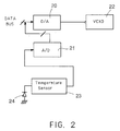
- the DTCXO as seen in Fig. 2, comprises a digital-to-analog (D/A) converter 20, and analog-to-digital (A/D) converter 21, a voltage controlled crystal oscillator (VCXO) 22, and a temperature sensor 23 coupled to a sensing diode 24.
- the sensed temperature value is translated into a voltage by the temperature sensing circuit 23, and the circuit output voltage is changed according to every sensed temperature.
- the output of the temperature sensor circuit is fed to the A/D 21, which translates the voltage levels into bytes that are read by the data bus of the microcontroller 3.
- analog LSI of Fig. 1 can be replaced by appropriate circuits for the DTCXO and the transversal filter, according to another preferred embodiment of the invention.
- a separate figure is not provided, for the sake of brevity, as this substitution is clear to the skilled person.
- EEPROM 14 contains a table in which the compensation values for the VCO 22 (Fig. 2) are stored. These values are read by microcontroller 3, which writes the appropriate values into the input of the D/A convertor 20. The D/A output voltage is fed into the VCO compensation voltage input so as to maintain its frequency within ⁇ 1 ppm through the full operating range.
- the Analog LSI 12 also contains a transversal filter 15.
- This filter and its use, within the context of this invention, are novel and as such also form a part of the invention.
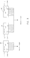
- the filter 15 provides the transmitter 7 with a sine-shaped bit stream on its real (I) and imaginary (Q) outputs. This is further illustrated in Fig. 3, in which the functional diagram of filter 15 is shown.
- the (I) data bit stream input to shift register 30 is converted into an analog shaped data output which is the sum of the shift register outputs divided by the respective resistors values.
- the (Q0) and (Q1) data bit streams inputs to shift registers 31 and 32 respectively, and are converted to an analog shaped data output which is the sum of the output of the shift registers divided by the respective resistor values.
- the transversal filter if properly designed, specifically by the proper selection of resistor values, together with the shaping function design implemented in the digital shaper 10 (Fig. 1), optimizes the tradeoff required by the system to meet both the FCC and the location accuracy requirements.
- the 908M synthesizer 16 which is conventional in construction, is interfaced with the Analog LSI 12.
- the synthesizer is based on a frequency multiplier which multiplies the reference DTCXO frequency and provides local oscillator for both the receiver and the transmitter sections.
- a power supply means which can be supplied by the battery of the vehicle, or by an external battery, is of conventional type, and is therefore not discussed herein in detail.
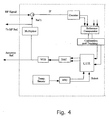
- Fig. 4 illustrates an additional improvement of the DTCXO circuit intended to solve drift problems caused by crystal aging. This is done, according to one embodiment of the invention, using the receive channel signal as a reference frequency.
- the TCXO system is based on a standard VCO (voltage controlled oscillator) controlled by the system.
- VCO voltage controlled oscillator
- the compensation value from the L.U.T (look-up table) driven by DAC (Digital to Analog Converter) is used to control the VCO.
- the address to the L.U.T. is based on a T.S. (Temperature Sensor) driven by ADC.
- the L.U.T. is filled during a calibration procedure and updated (for aging) during the tracking procedure.
- the system uses the received RF signal of the FCM (Forward Channel Messages).
- the VCO frequency is multiplied to generate REF1 frequency for down-converting the FCM RF signal to IF level.
- the IF frequency is counted in the calibration counter and compared to a reference count. The deviation of the measured IF frequency from a known reference IF frequency generates an offset value added to the L.U.T value for the appropriate address according to the temperature sensor output.
- the device according to the invention can be provided in many different embodiments.
- the Digital LSI 5 can be engineered to contain a more limited number of functional elements, e.g., the signal processor 6 or the digital shaper 10 could be conventional units, external to, and interfaced with, LSI 5. While this arrangement would diminish some of the advantages of the invention, by increasing the cost of the unit, decreasing it reliability, due to the increased number of elements, and being in general less desirable, it would by no means exceed the scope and spirit of the present invention.
Abstract
Description
- The present invention relates to a vehicle location system. More particularly, the invention relates to an improved unit to be incorporated in a vehicle.
- Vehicle Location Systems (VLS) have been used for some time. Such systems comprise transmitting/receiving stations which are capable of transmitting signals specific to a given vehicle, which signals are received by the Vehicle Location Unit (VLU) of the vehicle, which in turn emits signals which are received by the various receiving stations. Receipt of a signal by four or more receiving stations makes it possible to determine the exact location of the vehicle.
- These systems have a variety of applications. For instance, they are used in controlling the movement of commercial vehicles, such as lorries and taxis, busses or other vehicles the operation of which requires coordination and control. Another interesting application is the location of stolen property, particularly motorcars, or of vehicles in which an emergency situation has occurred. A motorcar incorporating a VLU can be located at all times by its VLS, through the various receiving stations positioned at different locations. Vehicle locating systems of various types are described, e.g., in U.S. Patent 4,905,271, JP 02-57450, JP 01-177724 and JP 63-235877.
- The use of these systems, however, has been limited so far due to a number of problems related to the VLU. First of all, because of their design, which utilizes conventional off the shelf radio components, the VLUs sold today are prohibitively expensive, and cannot be normally afforded by private users. This, as will be appreciated, considerably limits the applicability of these systems which could be conveniently exploited virtually in every vehicle if this problem were solved.
- Another considerable drawback of existing VLUs resides in their high power consumption. Prior art VLUs have a power consumption of more than 100 mA at 12 V, and because of such high power consumption, the VLU cannot operate continuously and must be switched off when the motor is turned off, or shortly thereafter. Commercially available VLUs are normally automatically switched off about 4 hours after the motor is turned off. This means that during certain periods of time the location of the vehicle cannot be verified through this system.
- An additional, and severe, drawback of existing VLUs is their relatively low reliability, due to the large number of components which must operate in a difficult environment, under mechanical and thermal shocks. Because of these factors, a high failure rate of the VLUs is seen.
- It is therefore clear that it would be highly desirable to be able to overcome the aforesaid drawbacks, and to permit thereby a widespread and everyday use of VLUs to the general public.
- It is an object of the present invention to provide a VLU which overcomes the aforesaid drawbacks, which is inexpensive, highly reliable and which does not require high power consumption. The VLU hereinafter described has an average power consumption of less than 40 mA at 13.6 VDC.
- It is another object of the invention to provide improved functional components which permit to carry out the operations required by the VLU in an effective and inexpensive manner.
- The VLU device according to the invention comprises, in functional relationship, the following elements:
- 1. an RF receiver;
- 2. a transmitter;
- 3. a receive/transmit switch;
- 4. a microcontroller to control the receiving/transmitting path;
- 5. a digital LSI, comprising digital signal processing means; and
- 6. crystal oscillator and filtering means for the outcoming signal; coupled to conventional circuit elements, such as memory means, power supply means, etc.
- According to a preferred embodiment of the invention, the crystal oscillator and filtering means are comprised in an analog LSI. In another preferred embodiment of the invention, the crystal oscillator and filtering means are provided as separate circuits.
- As will be detailed hereinafter, the invention is not only directed to the VLU described above, but also encompasses novel elements and combinations of elements, which can be exploited in manufacturing VLUs according to preferred embodiments of the invention. All the above and other advantages and characteristics of the invention will be better understood through the following illustrative and non-limitative description of a preferred embodiment.
-
- Fig. 1 is a block diagram of a VLU according to one particular embodiment of the invention;
- Fig 2 illustrates the digital temperature compensated crystal oscillator (DTCXO) employed in the LSI of the VLU of Fig. 1;
- Fig. 3 is a diagram of the transversal filter employed in the VLU of the invention; and
- Fig. 4 is a diagram of a TCXO system used when the analog LSI of Fig. 1 is replaced by separate circuits for the DTCXO and the transversal filter.
- Referring to Fig. 1,
numeral 1 is an antenna which is connected, through receive/transmit switch 2, either to the receiving or the transmitting path. The operation of theswitch 2 is controlled by themicrocontroller 3, which signals whether the transmitting or the receiving path are to be activated at any given time. - The signals normally employed in VLSs are 925 MHz FSK modulated signals. Looking now at the receiving path, the
RF receiver 4 converts the received signals into 2400 bits/sec baseband signals, and transmits them to thedigital LSI 5. In thedigital LSI 5 the incoming signal data are first decoded by theprocessor 6. The operation of theprocessor 6 is as follows. The data is first processed by a bit synchronizer circuit which samples the incoming bits and corrects for the difference between the system PAGER clock and the VLU clock. The output of the bit synchronizer circuit is fed to a SYNC/ADDRESS decoder, which looks for a correlation between the detected Sync word and the known Sync word, and does the same for the VLU specific address (ID) versus the detected one. This permits to make sure that proper identification of the VLU is effected. The various circuits, such as the synchronizer circuit and the SYNC/ADDRESS decoder, are conventional and providing them is within the scope of the skilled engineer. Therefore, for the sake of brevity and simplicity, such conventional circuits and means, when referred to herein, are not described in detail, it being understood that the general teachings of the art in this respect are incorporated herein by reference. - Once the decoder has detected the SYNC word, the VLU is synchronized and address detection can be carried out. The positive output of the address detection circuit, indicating that detection has been successfully carried out, interrupts the
microcontroller 3, which activates thetransmitter 7 at the predetermined timing. - The timing and
control circuit 8 initializes and stops the various procedures which take place during reception and transmission, by providing the necessary timing and control signals. It is an advantageous feature of the invention that the circuit parameters are set by the microcontroller, and therefore it is possible to employ the timing circuit outputs for each specific transmission/reception phase of operation of the VLU, since its operation can be easily programmed. This, as will be apparent to the skilled person, provides for an enhanced performance of the unit. - As will be appreciated, the output of the VLU must have a predetermined shape, according to the accepted standards. This is achieved by providing a
PN Generator circuit 9, which comprises a 10 bit register with feedback, which generates the required bit pattern. The PN data so generated are input to theDigital Shaper 10, which rotates them to provide the necessary shaping control signals. - The
ECM Generator 11 circuit comprises digital logic, dataloading register and a parallel load shift register. Themicrocontroller 3 loads the register at each "load" command with a byte the register feeds the shift register while the ECM digital logic controls the timing and the sequence of the synchronous load commands. The procedure is repeated 16 times, so that the shift register outputs the 128 ECM bits which are then received by the digital shaper. - The
analog LSI 12 is novel in design, and incorporates the analog section of a Digital Temperature Compensated Crystal Oscillator (DTCXO), designated bynumeral 13. The DTCXO, as seen in Fig. 2, comprises a digital-to-analog (D/A)converter 20, and analog-to-digital (A/D)converter 21, a voltage controlled crystal oscillator (VCXO) 22, and atemperature sensor 23 coupled to asensing diode 24. The sensed temperature value is translated into a voltage by thetemperature sensing circuit 23, and the circuit output voltage is changed according to every sensed temperature. The output of the temperature sensor circuit is fed to the A/D 21, which translates the voltage levels into bytes that are read by the data bus of themicrocontroller 3. - As stated, the analog LSI of Fig. 1 can be replaced by appropriate circuits for the DTCXO and the transversal filter, according to another preferred embodiment of the invention. A separate figure is not provided, for the sake of brevity, as this substitution is clear to the skilled person.
- Returning now to Fig. 1, the
microcontroller 3 is coupled to an erasable programmable read only memory, which according to a preferred embodiment of the invention isEEPROM 14.EEPROM 14 contains a table in which the compensation values for the VCO 22 (Fig. 2) are stored. These values are read bymicrocontroller 3, which writes the appropriate values into the input of the D/A convertor 20. The D/A output voltage is fed into the VCO compensation voltage input so as to maintain its frequency within ± 1 ppm through the full operating range. - The
Analog LSI 12 also contains atransversal filter 15. This filter and its use, within the context of this invention, are novel and as such also form a part of the invention. Thefilter 15 provides thetransmitter 7 with a sine-shaped bit stream on its real (I) and imaginary (Q) outputs. This is further illustrated in Fig. 3, in which the functional diagram offilter 15 is shown. As seen in this figure, the (I) data bit stream input to shiftregister 30 is converted into an analog shaped data output which is the sum of the shift register outputs divided by the respective resistors values. The (Q₀) and (Q₁) data bit streams inputs to shiftregisters - The transversal filter, if properly designed, specifically by the proper selection of resistor values, together with the shaping function design implemented in the digital shaper 10 (Fig. 1), optimizes the tradeoff required by the system to meet both the FCC and the location accuracy requirements.
- In Fig. 1, additional functional elements can be seen. The
908M synthesizer 16, which is conventional in construction, is interfaced with theAnalog LSI 12. The synthesizer is based on a frequency multiplier which multiplies the reference DTCXO frequency and provides local oscillator for both the receiver and the transmitter sections. Also a power supply means, which can be supplied by the battery of the vehicle, or by an external battery, is of conventional type, and is therefore not discussed herein in detail. - Fig. 4 illustrates an additional improvement of the DTCXO circuit intended to solve drift problems caused by crystal aging. This is done, according to one embodiment of the invention, using the receive channel signal as a reference frequency.
- As in the analog LSI, the TCXO system is based on a standard VCO (voltage controlled oscillator) controlled by the system. The compensation value from the L.U.T (look-up table) driven by DAC (Digital to Analog Converter) is used to control the VCO. The address to the L.U.T. is based on a T.S. (Temperature Sensor) driven by ADC.
- The L.U.T. is filled during a calibration procedure and updated (for aging) during the tracking procedure. As reference to the calibration and tracking loop, the system uses the received RF signal of the FCM (Forward Channel Messages). The VCO frequency is multiplied to generate REF1 frequency for down-converting the FCM RF signal to IF level. The IF frequency is counted in the calibration counter and compared to a reference count. The deviation of the measured IF frequency from a known reference IF frequency generates an offset value added to the L.U.T value for the appropriate address according to the temperature sensor output.
- As will be apparent to the skilled engineer, the device according to the invention can be provided in many different embodiments. For instance, the
Digital LSI 5 can be engineered to contain a more limited number of functional elements, e.g., thesignal processor 6 or thedigital shaper 10 could be conventional units, external to, and interfaced with,LSI 5. While this arrangement would diminish some of the advantages of the invention, by increasing the cost of the unit, decreasing it reliability, due to the increased number of elements, and being in general less desirable, it would by no means exceed the scope and spirit of the present invention.
Claims (11)
- A Vehicle Location Unit (VLU) device, comprising, in functional relationship, the following elements:1. an RF receiver (4);2. a transmitter (7);3. a receive/transmit switch (2);4. a microcontroller to control the receiving/transmitting path;5. a digital LSI, comprising digital signal processing means; and6. crystal oscillator and filtering means for the outcoming signal; conventional circuit elements, such as memory means, power supply means and the like also being provided.
- A VLU device according to claim 1, wherein the digital LSI comprises:1. a signal processor (6);2. timing and control means; (8);3. a PN generator (9);4. a digital shaper (10);5. an ECM generator (11);
- A VLU device according to claim 2, wherein the timing and control means is interfaced with the microcontroller and continuously receive circuit parameters therefrom.
- A VLU device according to claim 1, wherein the crystal oscillator is a Digital Temperature Compensated Crystal Oscillator (DTCXO).
- A VLU device according to claim 1, wherein the filtering means comprise a transversal filter.
- A device according to claim 1, wherein the microcontroller is coupled to memory means (14).
- A device according to claim 6, wherein the memory means is an EPROM, preferably an EEPROM.
- A device according to claim 4, wherein the DTCXO comprises temperature sensing means coupled to A/D converting means, and a Voltage Controlled Crystal Oscillator (VCXO) coupled to D/A converting means, and means for reading compensation values for the VCXO from a data bus which contains prestored compensation values.
- A device according to claim 8, wherein the compensation values are stored in the EEPROM coupled to the microcontroller (3).
- A device according to any one of claims 1 to 9, wherein the crystal oscillator and filtering means are comprised in an analog LSI (12).
- A device according to any one of claims 1 to 9, wherein the crystal oscillator and filtering means are provided as separate circuits.
Applications Claiming Priority (2)
| Application Number | Priority Date | Filing Date | Title |
|---|---|---|---|
| IL102051 | 1992-05-29 | ||
| IL10205192A IL102051A (en) | 1992-05-29 | 1992-05-29 | Vehicle location unit |
Publications (2)
| Publication Number | Publication Date |
|---|---|
| EP0572082A2 true EP0572082A2 (en) | 1993-12-01 |
| EP0572082A3 EP0572082A3 (en) | 1994-06-22 |
Family
ID=11063674
Family Applications (1)
| Application Number | Title | Priority Date | Filing Date |
|---|---|---|---|
| EP19930201468 Withdrawn EP0572082A3 (en) | 1992-05-29 | 1993-05-24 | Vehicle location unit |
Country Status (3)
| Country | Link |
|---|---|
| US (1) | US5689820A (en) |
| EP (1) | EP0572082A3 (en) |
| IL (1) | IL102051A (en) |
Cited By (4)
| Publication number | Priority date | Publication date | Assignee | Title |
|---|---|---|---|---|
| FR2750509A1 (en) * | 1996-06-28 | 1998-01-02 | Mlr Electronique | RF receiver system for satellite reception |
| FR2750550A1 (en) * | 1996-06-28 | 1998-01-02 | Mlr Electronique | Satellite signal receiver e.g. for GPS |
| EP0893702A1 (en) * | 1997-06-30 | 1999-01-27 | Mlr Electronique | Satellite signal acquisition receiver |
| CN104391142A (en) * | 2014-12-22 | 2015-03-04 | 永新电子常熟有限公司 | Novel convenient signal generator |
Families Citing this family (3)
| Publication number | Priority date | Publication date | Assignee | Title |
|---|---|---|---|---|
| FI98330C (en) * | 1994-12-15 | 1997-05-26 | Nokia Mobile Phones Ltd | UHF synthesizer |
| US6323739B1 (en) * | 2000-01-18 | 2001-11-27 | Denso Corporation | Adjusting untrimmed VCO during operation of the oscillator |
| US8159336B2 (en) | 2009-12-21 | 2012-04-17 | Continental Automotive Systems Us, Inc. | Apparatus and method for maintaining communication with a stolen vehicle tracking device |
Citations (2)
| Publication number | Priority date | Publication date | Assignee | Title |
|---|---|---|---|---|
| US4897642A (en) * | 1988-10-14 | 1990-01-30 | Secura Corporation | Vehicle status monitor and management system employing satellite communication |
| GB2234140A (en) * | 1989-05-16 | 1991-01-23 | Samsung Electronics Co Ltd | Automatic vehicle location system |
Family Cites Families (14)
| Publication number | Priority date | Publication date | Assignee | Title |
|---|---|---|---|---|
| US4024880A (en) * | 1976-07-12 | 1977-05-24 | Edward Ray Newton | Infant pet arrival kit |
| JPS6211360A (en) * | 1985-07-09 | 1987-01-20 | Alpine Electron Inc | Burglarproof method for automobile |
| US4746879A (en) * | 1986-08-28 | 1988-05-24 | Ma John Y | Digitally temperature compensated voltage-controlled oscillator |
| US5179574A (en) * | 1986-09-29 | 1993-01-12 | Kabushiki Kaisha Kenwood | Spread PN code signal receiver |
| US4737969A (en) * | 1987-01-28 | 1988-04-12 | Motorola, Inc. | Spectrally efficient digital modulation method and apparatus |
| JPS63235877A (en) * | 1987-03-25 | 1988-09-30 | Toyo Commun Equip Co Ltd | Position measurement for radiolocation mobile station |
| DE3871893D1 (en) * | 1987-09-28 | 1992-07-16 | Siemens Ag | METHOD FOR TEMPERATURE COMPENSATION OF A VOLTAGE CONTROLLED QUARTZ OCILLATOR IN A PHASE CONTROL CIRCUIT. |
| JP2578347B2 (en) * | 1988-01-08 | 1997-02-05 | 富士通テン株式会社 | Vehicle dispatch processing method |
| JPH0257450A (en) * | 1988-08-22 | 1990-02-27 | Daihatsu Motor Co Ltd | System for controlling vehicle |
| US5056109A (en) * | 1989-11-07 | 1991-10-08 | Qualcomm, Inc. | Method and apparatus for controlling transmission power in a cdma cellular mobile telephone system |
| US5193215A (en) * | 1990-01-25 | 1993-03-09 | Olmer Anthony L | Location signalling device for automatically placing a radio distress call |
| US5103459B1 (en) * | 1990-06-25 | 1999-07-06 | Qualcomm Inc | System and method for generating signal waveforms in a cdma cellular telephone system |
| US5163159A (en) * | 1990-07-30 | 1992-11-10 | Motorola, Inc. | Dual mode automatic frequency control |
| JP2749456B2 (en) * | 1991-03-06 | 1998-05-13 | 三菱電機株式会社 | Wireless communication equipment |
-
1992
- 1992-05-29 IL IL10205192A patent/IL102051A/en not_active IP Right Cessation
-
1993
- 1993-05-24 EP EP19930201468 patent/EP0572082A3/en not_active Withdrawn
-
1996
- 1996-11-05 US US08/743,923 patent/US5689820A/en not_active Expired - Fee Related
Patent Citations (2)
| Publication number | Priority date | Publication date | Assignee | Title |
|---|---|---|---|---|
| US4897642A (en) * | 1988-10-14 | 1990-01-30 | Secura Corporation | Vehicle status monitor and management system employing satellite communication |
| GB2234140A (en) * | 1989-05-16 | 1991-01-23 | Samsung Electronics Co Ltd | Automatic vehicle location system |
Cited By (4)
| Publication number | Priority date | Publication date | Assignee | Title |
|---|---|---|---|---|
| FR2750509A1 (en) * | 1996-06-28 | 1998-01-02 | Mlr Electronique | RF receiver system for satellite reception |
| FR2750550A1 (en) * | 1996-06-28 | 1998-01-02 | Mlr Electronique | Satellite signal receiver e.g. for GPS |
| EP0893702A1 (en) * | 1997-06-30 | 1999-01-27 | Mlr Electronique | Satellite signal acquisition receiver |
| CN104391142A (en) * | 2014-12-22 | 2015-03-04 | 永新电子常熟有限公司 | Novel convenient signal generator |
Also Published As
| Publication number | Publication date |
|---|---|
| EP0572082A3 (en) | 1994-06-22 |
| IL102051A (en) | 1996-05-14 |
| IL102051A0 (en) | 1992-12-30 |
| US5689820A (en) | 1997-11-18 |
Similar Documents
| Publication | Publication Date | Title |
|---|---|---|
| EP0435607B1 (en) | Transponder | |
| US6888876B1 (en) | Frequency hopping spread spectrum communications system | |
| US4479215A (en) | Power-line carrier communications system with interference avoidance capability | |
| US5712628A (en) | Digitally programmable radio modules for transponder systems | |
| US4188582A (en) | Simulcast transmission system having phase-locked remote transmitters | |
| US5613195A (en) | Burst output timing control system in satellite communication system | |
| US6072404A (en) | Universal garage door opener | |
| JPH10184142A (en) | Automobile provided with central lock device and remote controller | |
| US6208694B1 (en) | Reduced power supervisory message transmission in a wireless alarm system | |
| EP0847631A1 (en) | Common receive module for a programmable digital radio | |
| AU657280B2 (en) | Radio transceiver having PLL synthesizer | |
| CA2184938A1 (en) | Code Division Multiple Access Mobile Communication System | |
| WO2002056489A3 (en) | Local oscillator leakage control in direct conversion processes | |
| CA2480846A1 (en) | Transceiver device | |
| US5155469A (en) | Wireless alarm system | |
| US5689820A (en) | Vehicle location unit | |
| JP2001189679A (en) | Automatic meter transponder system | |
| US4251801A (en) | Mobile data communication system | |
| US7502435B2 (en) | Two-point modulator arrangement and use thereof in a transmission arrangement and in a reception arrangement | |
| EP0839410A1 (en) | Radio receiver and method of calibrating same | |
| EP1164708B1 (en) | Long range two way low power communication device | |
| US7359448B2 (en) | Remote transmitter system and method | |
| JPH08130774A (en) | Data transmission system | |
| US20050277401A1 (en) | Heterodyne receiver and communication system | |
| GB2188212A (en) | Single frequency transceiver |
Legal Events
| Date | Code | Title | Description |
|---|---|---|---|
| PUAI | Public reference made under article 153(3) epc to a published international application that has entered the european phase |
Free format text: ORIGINAL CODE: 0009012 |
|
| AK | Designated contracting states |
Kind code of ref document: A2 Designated state(s): AT BE CH DE DK ES FR GB GR IE IT LI LU MC NL PT SE |
|
| PUAL | Search report despatched |
Free format text: ORIGINAL CODE: 0009013 |
|
| AK | Designated contracting states |
Kind code of ref document: A3 Designated state(s): AT BE CH DE DK ES FR GB GR IE IT LI LU MC NL PT SE |
|
| 17P | Request for examination filed |
Effective date: 19941116 |
|
| 17Q | First examination report despatched |
Effective date: 19961030 |
|
| STAA | Information on the status of an ep patent application or granted ep patent |
Free format text: STATUS: THE APPLICATION IS DEEMED TO BE WITHDRAWN |
|
| 18D | Application deemed to be withdrawn |
Effective date: 19970210 |