EP0573813A2 - Methode, coder and decoder for data transmission and/or storage - Google Patents
Methode, coder and decoder for data transmission and/or storage Download PDFInfo
- Publication number
- EP0573813A2 EP0573813A2 EP93107957A EP93107957A EP0573813A2 EP 0573813 A2 EP0573813 A2 EP 0573813A2 EP 93107957 A EP93107957 A EP 93107957A EP 93107957 A EP93107957 A EP 93107957A EP 0573813 A2 EP0573813 A2 EP 0573813A2
- Authority
- EP
- European Patent Office
- Prior art keywords
- blocks
- data
- address
- write
- block
- Prior art date
- Legal status (The legal status is an assumption and is not a legal conclusion. Google has not performed a legal analysis and makes no representation as to the accuracy of the status listed.)
- Granted
Links
Images
Classifications
-
- H—ELECTRICITY
- H04—ELECTRIC COMMUNICATION TECHNIQUE
- H04N—PICTORIAL COMMUNICATION, e.g. TELEVISION
- H04N7/00—Television systems
- H04N7/24—Systems for the transmission of television signals using pulse code modulation
- H04N7/52—Systems for transmission of a pulse code modulated video signal with one or more other pulse code modulated signals, e.g. an audio signal or a synchronizing signal
- H04N7/54—Systems for transmission of a pulse code modulated video signal with one or more other pulse code modulated signals, e.g. an audio signal or a synchronizing signal the signals being synchronous
-
- H—ELECTRICITY
- H04—ELECTRIC COMMUNICATION TECHNIQUE
- H04N—PICTORIAL COMMUNICATION, e.g. TELEVISION
- H04N19/00—Methods or arrangements for coding, decoding, compressing or decompressing digital video signals
- H04N19/85—Methods or arrangements for coding, decoding, compressing or decompressing digital video signals using pre-processing or post-processing specially adapted for video compression
- H04N19/89—Methods or arrangements for coding, decoding, compressing or decompressing digital video signals using pre-processing or post-processing specially adapted for video compression involving methods or arrangements for detection of transmission errors at the decoder
-
- H—ELECTRICITY
- H04—ELECTRIC COMMUNICATION TECHNIQUE
- H04N—PICTORIAL COMMUNICATION, e.g. TELEVISION
- H04N5/00—Details of television systems
- H04N5/76—Television signal recording
- H04N5/91—Television signal processing therefor
- H04N5/92—Transformation of the television signal for recording, e.g. modulation, frequency changing; Inverse transformation for playback
- H04N5/926—Transformation of the television signal for recording, e.g. modulation, frequency changing; Inverse transformation for playback by pulse code modulation
- H04N5/9261—Transformation of the television signal for recording, e.g. modulation, frequency changing; Inverse transformation for playback by pulse code modulation involving data reduction
- H04N5/9264—Transformation of the television signal for recording, e.g. modulation, frequency changing; Inverse transformation for playback by pulse code modulation involving data reduction using transform coding
-
- H—ELECTRICITY
- H04—ELECTRIC COMMUNICATION TECHNIQUE
- H04N—PICTORIAL COMMUNICATION, e.g. TELEVISION
- H04N19/00—Methods or arrangements for coding, decoding, compressing or decompressing digital video signals
- H04N19/10—Methods or arrangements for coding, decoding, compressing or decompressing digital video signals using adaptive coding
- H04N19/102—Methods or arrangements for coding, decoding, compressing or decompressing digital video signals using adaptive coding characterised by the element, parameter or selection affected or controlled by the adaptive coding
- H04N19/13—Adaptive entropy coding, e.g. adaptive variable length coding [AVLC] or context adaptive binary arithmetic coding [CABAC]
-
- H—ELECTRICITY
- H04—ELECTRIC COMMUNICATION TECHNIQUE
- H04N—PICTORIAL COMMUNICATION, e.g. TELEVISION
- H04N19/00—Methods or arrangements for coding, decoding, compressing or decompressing digital video signals
- H04N19/60—Methods or arrangements for coding, decoding, compressing or decompressing digital video signals using transform coding
-
- H—ELECTRICITY
- H04—ELECTRIC COMMUNICATION TECHNIQUE
- H04N—PICTORIAL COMMUNICATION, e.g. TELEVISION
- H04N19/00—Methods or arrangements for coding, decoding, compressing or decompressing digital video signals
- H04N19/65—Methods or arrangements for coding, decoding, compressing or decompressing digital video signals using error resilience
-
- H—ELECTRICITY
- H04—ELECTRIC COMMUNICATION TECHNIQUE
- H04N—PICTORIAL COMMUNICATION, e.g. TELEVISION
- H04N19/00—Methods or arrangements for coding, decoding, compressing or decompressing digital video signals
- H04N19/90—Methods or arrangements for coding, decoding, compressing or decompressing digital video signals using coding techniques not provided for in groups H04N19/10-H04N19/85, e.g. fractals
- H04N19/91—Entropy coding, e.g. variable length coding [VLC] or arithmetic coding
-
- H—ELECTRICITY
- H04—ELECTRIC COMMUNICATION TECHNIQUE
- H04N—PICTORIAL COMMUNICATION, e.g. TELEVISION
- H04N5/00—Details of television systems
- H04N5/76—Television signal recording
- H04N5/78—Television signal recording using magnetic recording
- H04N5/782—Television signal recording using magnetic recording on tape
- H04N5/783—Adaptations for reproducing at a rate different from the recording rate
Definitions
- the invention relates to a method, a coder and a decoder for data transmission and / or storage.
- EP-A-88100830 describes a method for data transmission in which data from pixel blocks are converted into transformed coefficients which are then encoded with a variable word length. The coefficients are coded in blocks with a fixed average length. Blocks that are not filled are filled with cached data from other blocks. In order to improve the sensitivity to interference, DC components and important AC components of the transformed coefficients are recorded at fixed intervals. If errors have occurred on the transmission channel or storage medium, however, the data of a block distributed to other blocks cannot be decoded.
- each of the blocks can additionally contain address pointer information which, after transmission and / or reading errors during the subsequent decoding, indicate addresses in a memory from which the separated data portions of blocks with a larger than the mean word length can be retrieved and used for decoding. Due to the additional address pointer information, however, a lower data rate is available for the image data while the channel capacity remains the same, which leads to a reduced image quality in the case of undisturbed decoding.
- the invention has for its object an improved To specify methods for data transmission and / or storage, which enables good image quality in normal operation and decoding even in the event of an error. This object is achieved by the method specified in claim 1.
- Known methods of image data reduction mean that blocks of data - in particular pixel data - have an average length of m bits. This average number of m bits is called the average block length m.
- the blocks are arranged during transmission or recording in such a way that the beginning of the block is at a fixed distance (grid) with the mean block length m.
- Each block (user data block) contains an address information flag FL, an address pointer with the LSB's of a physical address and the data (user bits) with the most important part of the data block source information for this block, for example, each from a DCT transformation (discrete cosine transform) a DC component and important, for example the larger, AC components.
- the actually required useful data length of the block is referred to below as the actual block length BL.
- the pointer address is used to temporarily store the data beyond the average block length so that it can be transferred to blocks with BL ⁇ m To transmit useful bits attached.
- the useful bits of the current useful data block are first transmitted and then, with the aid of the pointer address, the useful bits of other blocks exceeding the average block length are read from a buffer.
- recovery pointer pairs REC are inserted between a defined number, for example 6 to 8, of user data blocks or image lines - hereinafter referred to as block group. These recovery pointers are complete address words.
- the one pointer POI0 of this pair of pointers indicates a current write address for the buffer, from which to the middle one Data or alternating portions of blocks with BL> m going beyond the block length are buffered.
- the other pointer POI1 of this pair of pointers indicates a current read address for the buffer, from which the oldest data and alternating portions of blocks with BL> m that have not yet been transmitted and exceed the average block length have been buffered.
- the invention is based on the further object of specifying a coder for the method according to the invention. This object is achieved by the device specified in claim 6.
- the coder according to the invention is provided with a coding circuit which converts data section by section into digital signals with different word lengths, with a downstream multiplexer which, using downstream first storage means, forms blocks of constant, medium word length, selected data components, in particular a direct component and the most important alternating components with their associated addresses, from the sections of the digital signals for each of these blocks are stored in the first storage means and blocks with a shorter than the mean word length be filled with divided data portions of blocks with a larger than the mean word length, with a demultiplexer connected downstream of the storage means, which bundles the data belonging to a respective block and forwards it to a channel, with a circuit for address pointers fed by the first storage means. Calculation which controls the multiplexer and the demultiplexer and supplies the first storage means with an address information flag and a write or read address with a reduced word width for each block and a write and a read address with a full word width for each group of blocks.
- the invention is based on the further object of specifying a decoder for the method according to the invention. This object is achieved by the device specified in claim 7.
- the decoder is provided with an address pointer decoding circuit downstream of a channel for the separation and forwarding for each block of an address information flag and a write or read address with a reduced word width and for each group of blocks of a write and a read address with full word width to an address calculation circuit, with a multiplexer connected downstream of the address pointer decoding circuit, which, together with downstream second storage means, recovers data blocks in their original, different word lengths, with a downstream demultiplexer that bundles and connects the data belonging to a respective block forwards a variable-length decoder, at the output of which the source data during coding are available, the address calculation circuit controlling the multiplexer and the demultiplexer and corresponding to the second storage means Feeds addresses.
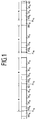
- the user data blocks with the average block length m contain, in addition to a direct component DC and an alternating component AC, additional address pointer information POI a ... h and an address information flag FL a ... h .
- the data of the first block have the index 'a', that of the second the index 'b' and that of, for example, eighth the index 'h'.
- the index '0' denotes a write pointer and the index '1' a read pointer.
- the remaining capacities of the blocks can be filled with additional data or alternating components AC x from other blocks.
- a block can contain further data required for decoding, for example a flag which indicates whether motion-adaptively coding was carried out with an 8 * 8 DCT or with a double 4 * 8 DCT and / or information about the activity in a block and / or error protection information.
- An 8 * 8 DCT is advantageously used for static picture content and a 2 * (4 * 8) DCT for dynamic picture content in interlace picture signals.
- recovery pointer pairs REC A , REC B , ... are additionally inserted at regular intervals, which comprise the full write and read address for buffer means, for example 20 bits each for a buffer of 1 Mbit, but the address pointer POI a.
- a user data block can contain FL / POI / DC or FL / POI / DC / AC or additionally AC x , AD or AC x / AD.
- control must be carried out using customary control methods (for example quantization) in such a way that there is no memory overflow or underflow during buffer storage.
- This regulation can be derived from the values of REC.
- a digital video recorder for example, it is possible to read related data tracks between one recovery pointer and the next (including error protection) from a storage medium at high intervals in a fast search. Based on the absolute address REC, the corresponding section of an image can then be shown in the correct place on a display.
- intraframe and interframe-coded pictures there are intraframe and interframe-coded pictures.
- Coded pixel blocks each contain an end-of-block identifier.
- interframe-coded pixel blocks can now be transmitted or recorded as additional data AD and intraframe-coded pixel blocks with the equal components DC and the alternating components AC or AC x , the end-of-block identifier of the intraframe-coded pixel blocks being omitted , because the block length BL can be determined on the decoder side from the pointer information.
- the interframe blocks can originate from different time ranges.
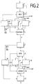
- a coder and decoder block diagram with which the transmission or storage according to the invention can be implemented.
- a coding circuit 1 for example, DCT-transformed image data are quantized, coded with variable length (VLC) and provided with addresses for alternating components.
- VLC variable length
- a downstream multiplexer 2 distributes the block data to the subsequent dual port RAMs 3 and 4.
- Recovery pointer pairs REC, address information flags FL and address pointer POI are written into a dual port RAM FIX 3 by a circuit for pointer calculation 13 as data information for each block. From this data, the pointer calculation circuit 13 likewise forms the address information for the dual-port RAM VAR 4 for the temporary storage of the useful bits that are now superfluous.
- the useful bits are merged again and transferred to the channel or the storage medium 6 together with the data REC, FL and POI.
- a circuit for address calculation 14 can provide the necessary address information for a dual-port RAM FIX 9 and for a dual-port RAM VAR 10.
- POI0 specifies the address on the decoder side up to which useful bits are read out from the dual-port RAM VAR 10 in the direction of the variable-length decoder 12.
- This decoder has an inverse function to the coding circuit 1.
- a corresponding multiplexer 8 is arranged between the address pointer decoder 7 and the RAMs 9 and 10, and a corresponding demultiplexer 11 is arranged between these RAMs and the variable-length decoder 12.
- other storage media such as magnetic disks or optical memories can also be used.
- a switch SW1 controlled by the pointer calculation circuit 13 can be located on the code side at the input of the dual-port RAM VAR 4, via which switch the additional data DA can be read in as described above.
- the corresponding switch SW2, controlled by the address calculation circuit 14 is used at the output of the dual-port RAM VAR 10 to output the additional data DA.
- the buffer control on the code side usually ensures that the read pointer does not 'overtake' the write pointer. This means that an attempt is made to read out information from the storage means which has not yet been written in at this time.
- the pointer calculation circuit 13 can additionally ensure this by a corresponding comparison of the pointers.
- a variable code word with a very long word length can be inserted into the data stream, which is not used on the decoder side.
- the surplus useful bits on the decoder side can last as long due to the outstanding transmission or storage be unavailable that when a block with BL ⁇ m arrives, these useful bits can no longer be assigned due to the limited memory capacity of the RAMs.
- data can be forcibly taken from the RAM 4 by appropriate control, for example one bit or byte per user data block or 10% of the average block length m. This removal is then compensated accordingly by the buffer control.
- the memory means on the encoder and decoder sides can advantageously be used simultaneously as a quantization buffer.
- the address difference between the write and read pointers indicates the fill level of this quantization buffer.
Abstract
Description
Die Erfindung betrifft ein Verfahren, einen Coder und einen Decoder zur Datenübertragung und/oder -speicherung.The invention relates to a method, a coder and a decoder for data transmission and / or storage.
In EP-A-88100830 wird ein Verfahren zur Datenübertragung beschrieben, bei dem Daten von Bildpunkt-Blöcken in transformierte Koeffizienten umgesetzt werden, die anschließend mit variabler Wortlänge codiert werden. Dabei werden die Koeffizienten in Blöcken mit einer festgelegten mittleren Länge codiert aufgezeichnet. Nicht ausgefüllte Blöcke werden mit zwischengespeicherten Daten von anderen Blöcken aufgefüllt. Um die Störempfindlichkeit zu verbessern, werden Gleichanteile und wichtige Wechselanteile der transformierten Koeffizienten in festen Abständen aufgezeichnet. Wenn Fehler auf dem Übertragungskanal bzw. Speichermedium aufgetreten sind, können jedoch die auf andere Blöcke verteilten Daten eines Blocks nicht decodiert werden.
Darum kann gemäß PCT/EP91/01954 jeder der Blöcke zusätzlich eine Adresspointer-Information enthalten, die nach Übertragungs- und/oder Lesefehlern bei der nachfolgenden Decodierung auf Adressen in einem Speicher hinweisen, aus denen die abgetrennten Daten-Anteile von Blöcken mit einer größeren als der mittleren Wortlänge wiedergewonnen und zur Decodierung genutzt werden können.
Durch die zusätzliche Adresspointer-Information steht allerdings bei gleichbleibender Kanalkapazität eine geringere Datenrate für die Bilddaten zur Verfügung, was bei ungestörter Decodierung zu einer verringerten Bildqualität führt.EP-A-88100830 describes a method for data transmission in which data from pixel blocks are converted into transformed coefficients which are then encoded with a variable word length. The coefficients are coded in blocks with a fixed average length. Blocks that are not filled are filled with cached data from other blocks. In order to improve the sensitivity to interference, DC components and important AC components of the transformed coefficients are recorded at fixed intervals. If errors have occurred on the transmission channel or storage medium, however, the data of a block distributed to other blocks cannot be decoded.
Therefore, according to PCT / EP91 / 01954, each of the blocks can additionally contain address pointer information which, after transmission and / or reading errors during the subsequent decoding, indicate addresses in a memory from which the separated data portions of blocks with a larger than the mean word length can be retrieved and used for decoding.
Due to the additional address pointer information, however, a lower data rate is available for the image data while the channel capacity remains the same, which leads to a reduced image quality in the case of undisturbed decoding.
Der Erfindung liegt die Aufgabe zugrunde, ein verbessertes Verfahren zur Datenübertragung und/oder -speicherung anzugeben, welches eine gute Bildqualität im Normalbetrieb und eine Decodierung auch im Fehlerfall ermöglicht. Diese Aufgabe wird durch das in Anspruch 1 angegebene Verfahren gelöst.The invention has for its object an improved To specify methods for data transmission and / or storage, which enables good image quality in normal operation and decoding even in the event of an error. This object is achieved by the method specified in claim 1.
Durch bekannte Verfahren der Bilddaten-Reduktion wird erreicht, daß Blöcke von Daten - insbesondere Bildpunktdaten - im Mittel eine Länge von m Bit erhalten. Diese durchschnittliche Anzahl von m Bits wird mittlere Blocklänge m genannt. Die Blöcke werden bei der Übertragung bzw. Aufzeichnung so angeordnet, daß die Blockanfänge im festen Abstand (Raster) mit der mittleren Blocklänge m liegen.
Jeder Block (Nutzdatenblock) enthält ein Adressinformations-Flag FL, einen Adresspointer mit den LSB's einer physikalischen Adresse und die Daten (Nutz-Bits) mit dem wichtigsten Anteil an der Datenblock-Quellinformation für diesen Block, z.B. jeweils aus einer DCT-Transformation (discrete cosine transform) einen Gleichanteil und wichtige, z.B. die größeren, Wechselanteile. Die eigentlich erforderliche Nutzdaten-Länge des Blocks wird im Folgenden als tatsächliche Blocklänge BL bezeichnet. BL kann größer, gleich oder kleiner als die mittlere Blocklänge m sein. Wenn z.B. BL > m, so ist FL = 0 und wenn BL ≦ m, so ist FL = 1. Im ersten Fall werden mit Hilfe der Pointeradresse die über die mittlere Blocklänge hinausgehenden Daten zwischengespeichert, um sie bei Blöcken mit BL < m an die Nutzbits angehängt zu übertragen. Im zweiten Fall werden zunächst die Nutzbits des aktuellen Nutzdatenblocks übertragen und anschließend mit Hilfe der Pointeradresse die über die mittlere Blocklänge hinausgehenden Nutzbits anderer Blöcke aus einem Zwischenspeicher ausgelesen. Für das erfindungsgemäße Verfahren ist es gleichwertig, ob der Fall BL = m dem Adressinformations-Flag FL '0' oder '1' zugeordnet wird.
Zusätzlich sind jeweils zwischen einer festgelegten Anzahl, z.B. 6 bis 8, von Nutzdatenblöcken oder Bildzeilen - im folgenden Blockgruppe genannt - Recovery-Pointerpaare REC eingefügt. Diese Recovery-Pointer sind vollständige Adress-Worte. Der eine Pointer POI0 dieses Pointerpaars gibt eine aktuelle Schreibadresse für den Zwischenspeicher an, von der an die über die mittlere Blocklänge hinausgehenden Daten- bzw. Wechselanteile von Blöcken mit BL > m zwischengespeichert werden. Der andere Pointer POI1 dieses Pointerpaars gibt eine aktuelle Leseadresse für den Zwischenspeicher an, ab der die jeweils noch nicht übertragenen ältesten, über die mittlere Blocklänge hinausgehenden Daten- bzw. Wechselanteile von Blöcken mit BL > m zwischengespeichert wurden.
Vorteilhaft können durch die Verwendung des Recovery-Pointerpaars und der auf die LSB's verkürzten Adresspointer auch Zusatzdaten in den vorhandenen Datenstrom ohne Funktions-Störung der beschriebenen Codierung/Decodierung eingefügt werden. Dies kann z.B. am Ende der Blöcke geschehen.Known methods of image data reduction mean that blocks of data - in particular pixel data - have an average length of m bits. This average number of m bits is called the average block length m. The blocks are arranged during transmission or recording in such a way that the beginning of the block is at a fixed distance (grid) with the mean block length m.
Each block (user data block) contains an address information flag FL, an address pointer with the LSB's of a physical address and the data (user bits) with the most important part of the data block source information for this block, for example, each from a DCT transformation (discrete cosine transform) a DC component and important, for example the larger, AC components. The actually required useful data length of the block is referred to below as the actual block length BL. BL can be larger, equal to or smaller than the average block length m. For example, if BL> m, then FL = 0 and if BL ≦ m, then FL = 1. In the first case, the pointer address is used to temporarily store the data beyond the average block length so that it can be transferred to blocks with BL <m To transmit useful bits attached. In the second case, the useful bits of the current useful data block are first transmitted and then, with the aid of the pointer address, the useful bits of other blocks exceeding the average block length are read from a buffer. For the method according to the invention, it is equivalent whether the case BL = m is assigned to the address information flag FL '0' or '1'.
In addition, recovery pointer pairs REC are inserted between a defined number, for example 6 to 8, of user data blocks or image lines - hereinafter referred to as block group. These recovery pointers are complete address words. The one pointer POI0 of this pair of pointers indicates a current write address for the buffer, from which to the middle one Data or alternating portions of blocks with BL> m going beyond the block length are buffered. The other pointer POI1 of this pair of pointers indicates a current read address for the buffer, from which the oldest data and alternating portions of blocks with BL> m that have not yet been transmitted and exceed the average block length have been buffered.
By using the recovery pointer pair and the address pointer shortened to the LSBs, additional data can advantageously also be inserted into the existing data stream without malfunctioning of the coding / decoding described. This can happen, for example, at the end of the blocks.
Im Prinzip dient das erfindungsgemäße Verfahren zur Datenübertragung und/oder -speicherung, bei der coderseitig Daten zunächst abschnittsweise in Digitalsignale mit unterschiedlicher Wortlänge umgesetzt und danach unter Verwendung von ersten Speichermitteln Blöcken konstanter, mittlerer Wortlänge zugewiesen werden, wobei ausgewählte Daten-Anteile - insbesondere aus jeweils einer Bildpunktblock-Transformation ein Gleichanteil und die wichtigsten Wechselanteile - aus den Abschnitten der Digitalsignale in jedem dieser Blöcke angeordnet sind und anschließend Blöcke mit einer geringeren als der mittleren Wortlänge, die vorher unter Verwendung von Adresspointer-Information mit Schreib- und Leseadressen in den Speichermitteln zwischengespeichert wurden, mit abgeteilten Daten-Anteilen von Blöcken mit einer größeren als der mittleren Wortlänge aufgefüllt werden, wobei Adress-Information mit übertragen und/oder gespeichert wird, und decoderseitig die Blöcke unter Verwendung von zweiten Speichermitteln und der Adress-Information in ihrer ursprünglichen, unterschiedlichen Wortlänge entsprechend wiedergewonnen werden, indem die abgeteilten Daten-Anteile von Blöcken mit einer größeren als der mittleren Wortlänge jeweils zu den zeitlich zugehörigen ausgewählten Daten-Anteilen hinzugefügt werden, wobei coderseitig:
- vor dem Beginn jeder Gruppe von einer festgelegten Anzahl von Blöcken eine entsprechende Schreib- und Lese-Adresse mit voller Wortbreite übertragen und/oder aufgezeichnet wird;
- die zu einem Block zugehörige Adresspointer-Information nur eine solche Anzahl von LSB's der vollen Wortbreite der Schreib- oder Leseadresse für den Block enthält, die der Differenz zwischen einer festgelegten maximalen Wortlänge und der mittleren Wortlänge entspricht,
und daß decoderseitig: - die Schreib- und die Leseadressen mit der vollen Wortbreite für die Blockgruppen und die Schreib- oder Leseadressen für jeden Block aus dem übertragenen und/oder aufgezeichneten Datenstrom ermittelt werden;
- die Blöcke unter Verwendung von zweiten Speichermitteln und diesen Adressen in ihrer ursprünglichen, unterschiedlichen Wortlänge entsprechend wiedergewonnen werden, indem die abgeteilten Daten-Anteile von Blöcken mit einer größeren als der mittleren Wortlänge jeweils zu den zeitlich zugehörigen ausgewählten Daten-Anteilen hinzugefügt werden, wobei nach einer Unterbrechung oder Störung des übertragenen und/oder aufgezeichneten Datenstroms mit Hilfe der Schreib- und der Leseadressen mit der vollen Wortbreite eine fehlerfreie Wiederaufnahme der Decodierung ermöglicht ist.
- before the start of each group of a specified number of blocks, a corresponding write and read address with full word width is transmitted and / or recorded;
- the address pointer information associated with a block contains only such a number of LSBs of the full word length of the write or read address for the block that corresponds to the difference between a specified maximum word length and the mean word length,
and that on the decoder side: - the write and read addresses with the full word width for the block groups and the write or read addresses for each block are determined from the transmitted and / or recorded data stream;
- the blocks are recovered using second storage means and these addresses in their original, different word lengths accordingly, in that the divided data portions of blocks with a greater than the mean word length are each added to the temporally associated selected data portions, after one Interruption or disturbance of the transmitted and / or recorded data stream with the help of the write and read addresses with the full word width enables error-free resumption of the decoding.
Vorteilhafte Weiterbildungen des erfindungsgemäßen Verfahrens ergeben sich aus den zugehörigen abhängigen Ansprüchen.Advantageous developments of the method according to the invention result from the associated dependent claims.
Der Erfindung liegt die weitere Aufgabe zugrunde, einen Coder für das erfindungsgemäße Verfahren anzugeben. Diese Aufgabe wird durch die in Anspruch 6 angegebene Vorrichtung gelöst.The invention is based on the further object of specifying a coder for the method according to the invention. This object is achieved by the device specified in
Im Prinzip ist der erfindungsgemäße Coder versehen mit einer Codierschaltung, die Daten abschnittsweise in Digitalsignale mit unterschiedlicher Wortlänge umgesetzt, mit einem nachgeschalteten Multiplexer, der unter Verwendung von nachgeschalteten ersten Speichermitteln Blöcke konstanter, mittlerer Wortlänge bildet, wobei ausgewählte Daten-Anteile, insbesondere ein Gleichanteil und die wichtigsten Wechselanteile mit ihren zugehörigen Adressen, aus den Abschnitten der Digitalsignale für jeden dieser Blöcke in den ersten Speichermitteln gespeichert werden und Blöcke mit einer geringeren als der mittleren Wortlänge mit abgeteilten Daten-Anteilen von Blöcken mit einer größeren als der mittleren Wortlänge aufgefüllt werden, mit einem den Speichermitteln nachgeschalteten Demultiplexer, der die zu einem jeweiligen Block zugehörenden Daten bündelt und zu einem Kanal weiterleitet, mit einer von den ersten Speichermitteln gespeisten Schaltung zur Adresspointer-Berechnung, die den Multiplexer und den Demultiplexer steuert und den ersten Speichermitteln für jeden Block ein Adressinformations-Flag und eine Schreib- oder Leseadresse mit reduzierter Wortbreite und für jede Gruppe von Blöcken eine Schreib- und eine Leseadresse mit voller Wortbreite zuführt.In principle, the coder according to the invention is provided with a coding circuit which converts data section by section into digital signals with different word lengths, with a downstream multiplexer which, using downstream first storage means, forms blocks of constant, medium word length, selected data components, in particular a direct component and the most important alternating components with their associated addresses, from the sections of the digital signals for each of these blocks are stored in the first storage means and blocks with a shorter than the mean word length be filled with divided data portions of blocks with a larger than the mean word length, with a demultiplexer connected downstream of the storage means, which bundles the data belonging to a respective block and forwards it to a channel, with a circuit for address pointers fed by the first storage means. Calculation which controls the multiplexer and the demultiplexer and supplies the first storage means with an address information flag and a write or read address with a reduced word width for each block and a write and a read address with a full word width for each group of blocks.
Der Erfindung liegt die weitere Aufgabe zugrunde, einen Decoder für das erfindungsgemäße Verfahren anzugeben. Diese Aufgabe wird durch die in Anspruch 7 angegebene Vorrichtung gelöst.The invention is based on the further object of specifying a decoder for the method according to the invention. This object is achieved by the device specified in
Im Prinzip ist der erfindungsgemäße Decoder versehen mit einer einem Kanal nachgeschalteten Adresspointer-Decodierschaltung zur Abtrennung und Weiterleitung für jeden Block eines Adressinformations-Flags und einer Schreib- oder Leseadresse mit reduzierter Wortbreite und für jede Gruppe von Blöcken einer Schreib- und eine Leseadresse mit voller Wortbreite an eine Adress-Berechnungs-Schaltung, mit einem der Adresspointer-Decodierschaltung nachgeschalteten Multiplexer, der zusammen mit nachgeschalteten zweiten Speichermitteln Daten-Blöcke in ihrer ursprünglichen, unterschiedlichen Wortlänge wiedergewinnt, mit einem nachgeschalteten Demultiplexer, der die zu einem jeweiligen Block zugehörenden Daten bündelt und zu einem Variable-length-Decoder weiterleitet, an dessen Ausgang den Quell-Daten bei der Codierung entsprechende Daten zur Verfügung stehen, wobei die Adress-Berechnungs-Schaltung den Multiplexer und den Demultiplexer steuert und den zweiten Speichermitteln entsprechende Adressen zuführt.In principle, the decoder according to the invention is provided with an address pointer decoding circuit downstream of a channel for the separation and forwarding for each block of an address information flag and a write or read address with a reduced word width and for each group of blocks of a write and a read address with full word width to an address calculation circuit, with a multiplexer connected downstream of the address pointer decoding circuit, which, together with downstream second storage means, recovers data blocks in their original, different word lengths, with a downstream demultiplexer that bundles and connects the data belonging to a respective block forwards a variable-length decoder, at the output of which the source data during coding are available, the address calculation circuit controlling the multiplexer and the demultiplexer and corresponding to the second storage means Feeds addresses.
Anhand der Zeichnungen sind Ausführungsbeispiele der Erfindung beschrieben. Die Zeichnungen zeigen in:
- Fig. 1
- erfindungsgemäße Anordnung von Recovery-Information und Nutzdaten-Blöcken;
- Fig. 2
- Blockschaltbild für einen erfindungsgemäßen Coder und Decoder.
- Fig. 1
- arrangement of recovery information and user data blocks according to the invention;
- Fig. 2
- Block diagram for a coder and decoder according to the invention.
In Fig. 1 enthalten die Nutzdaten-Blöcke mit der mittleren Blocklänge m außer einem Gleichanteil DC und einem Wechselanteil AC zusätzlich eine Adresspointer-Information POIa...h und ein Adressinformations-Flag FLa...h. Die Daten des ersten Blocks tragen den Index 'a', die des zweiten den Index 'b' und die eines z.B. achten den Index 'h'. Der Index '0' bezeichnet einen Schreibpointer und der Index '1' einen Lesepointer. Die Restkapazitäten der Blöcke können mit zusätzlichen Daten bzw. Wechselanteilen ACx aus anderen Blöcken aufgefüllt werden. Zusätzlich kann ein Block weitere für die Decodierung benötigte Daten enthalten, z.B. ein Flag, welches anzeigt, ob bewegungsadaptiv mit einer 8*8-DCT oder mit einer doppelten 4*8-DCT codiert wurde und/oder Information über die Aktivität in einem Block und/oder Fehlerschutzinformation. Eine 8*8-DCT wird vorteilhaft bei statischem Bildinhalt verwendet und eine 2*(4*8)-DCT bei dynamischem Bildinhalt in Interlace-Bildsignalen.
Erfindungsgemäß werden zusätzlich in regelmäßigen Abständen Recovery-Pointerpaare RECA, RECB, ..., eingefügt, die die volle Schreib- und Leseadresse für Zwischenspeichermittel umfassen mit z.B. jeweils 20 Bit für einen Zwischenspeicher von 1 Mbit, wobei jedoch die Adresspointer POIa...h für den aktuellen Block nur jeweils die letzten Bits einer Lese- oder Schreibadresse für den Zwischenspeicher enthalten: POI₀ bzw. ![]()
Die Wortlänge der Adresspointer entspricht dabei der maximal auftretenden bzw. zulässigen Anzahl der Bits eines Nutzdatenblocks oder der Nutzbits, minus der mittleren Blocklänge m. Hat ein großer Block z.B. 500 Bit, so ist die Wortlänge der Adresspointer auf minimal 9 Bit (2⁹ = 512) zu bemessen.In FIG. 1, the user data blocks with the average block length m contain, in addition to a direct component DC and an alternating component AC, additional address pointer information POI a ... h and an address information flag FL a ... h . The data of the first block have the index 'a', that of the second the index 'b' and that of, for example, eighth the index 'h'. The index '0' denotes a write pointer and the index '1' a read pointer. The remaining capacities of the blocks can be filled with additional data or alternating components AC x from other blocks. In addition, a block can contain further data required for decoding, for example a flag which indicates whether motion-adaptively coding was carried out with an 8 * 8 DCT or with a double 4 * 8 DCT and / or information about the activity in a block and / or error protection information. An 8 * 8 DCT is advantageously used for static picture content and a 2 * (4 * 8) DCT for dynamic picture content in interlace picture signals.
According to the invention, recovery pointer pairs REC A , REC B , ... are additionally inserted at regular intervals, which comprise the full write and read address for buffer means, for example 20 bits each for a buffer of 1 Mbit, but the address pointer POI a. ..h only contain the last bits of a read or write address for the buffer for the current block: POI₀ or ![]()
The word length of the address pointer corresponds to the maximum occurring or permissible number of bits of a user data block or the user bits, minus the average block length m. For example, if a large block has 500 bits, the word length of the address pointer must be at least 9 bits (2⁹ = 512).
Ist z.B. m = 20 Bit und BL = 50 bit und steht der Schreibpointer POI0 von den Recovery-Pointern RECA auf der physikalischen Adresse 100 und der Lesepointer POI1 auf der physikalischen Adresse 0, so ist im nächstfolgenden Nutzdatenblock FLa = 0 und POI0a = 100+|50-20| = 130. Hat der danach folgende Block BL = 18, so ist in diesem Nutzdatenblock FLb = 1 und POI1b = 0+|18-20| = 2. Hat der folgende Block BL = 30, so ist FLc = 0 und POI0c = 130+|30-20| = 140. Werden, wie weiter unten beschrieben, keine Zusatzdaten AD eingefügt, so ergeben sich die Recovery-Pointer RECB durch entsprechende Aufsummierung der Werte für POIa...h.For example, if m = 20 bits and BL = 50 bits and the POI0 write pointer from the REC A recovery pointer is at the physical address 100 and the POI1 read pointer is at the physical address 0, FL a = 0 and POI 0a in the next user data block = 100+ | 50-20 | = 130. If the subsequent block BL = 18, then FL b = 1 and POI 1b = 0+ | 18-20 | in this user data block = 2. If the following block has BL = 30, then FL c = 0 and POI 0c = 130+ | 30-20 | = 140. If, as described further below, no additional data AD is inserted, the recovery pointer REC B results from a corresponding summation of the values for POI a ... h .
Durch die erfindungsgemäße Aufteilung der Pointerinformationen werden z.B. alle 6-8 Blöcke zusätzlich 2*20 Bit benötigt, aber bei jeden Nutzdatenblock werden gegenüber PCT/EP91/01954 20-9 Bit = 11 Bit eingespart. Die Gesamt-Datenrate für die Pointerinformation sinkt und die Qualität der (Bild-)Datencodierung kann entsprechend steigen. Nach einer Übertragungs- oder Wiedergabestörung kann mit Hilfe der Recovery-Pointer weiter fehlerfrei decodiert werden.By dividing the pointer information according to the invention, e.g. every 6-8 blocks an additional 2 * 20 bits are required, but with each user data block 20-9 bits = 11 bits are saved compared to PCT / EP91 / 01954. The overall data rate for the pointer information drops and the quality of the (image) data coding can increase accordingly. After a transmission or playback fault, the recovery pointer can be used to continue decoding without errors.
Besonders vorteilhaft ist, daß aufgrund der doppelten Pointer REC und POI zusätzliche Daten AD in den bisher beschriebenen Datenstrom eingefügt werden können, ohne die Funktion zu stören, auch nach einem Fehler.
Ein Nutzdatenblock kann FL/POI/DC bzw. FL/POI/DC/AC oder zusätzlich ACx, AD oder ACx/AD enthalten. In jedem Fall muß bei nicht konstantem Gesamt-Datenstrom mit üblichen Regelverfahren (z.B. Quantisierung) so gesteuert werden, daß bei der Zwischenspeicherung kein Speicherüber- oder Unterlauf entsteht. Diese Regelung kann aus den Werten von REC abgeleitet werden.
Bei z.B. einem digitalen Videorecorder ist es möglich, im schnellen Suchlauf in gewissen Abständen zusammenhängende Datenspuren zwischen einem Recovery-Pointer und dem nächsten (inclusive eines Fehlerschutzes) von einem Speichermedium zu lesen. Aufgrund der absoluten Adresse REC kann dann der entsprechende Ausschnitt eines Bildes an der richtigen Stelle auf einem Display dargestellt werden.It is particularly advantageous that, due to the double pointer REC and POI, additional data AD can be inserted into the previously described data stream without disturbing the function, even after an error.
A user data block can contain FL / POI / DC or FL / POI / DC / AC or additionally AC x , AD or AC x / AD. In any case, if the total data stream is not constant, control must be carried out using customary control methods (for example quantization) in such a way that there is no memory overflow or underflow during buffer storage. This regulation can be derived from the values of REC.
With a digital video recorder, for example, it is possible to read related data tracks between one recovery pointer and the next (including error protection) from a storage medium at high intervals in a fast search. Based on the absolute address REC, the corresponding section of an image can then be shown in the correct place on a display.
Bei bestimmten Codiermethoden für die Übertragung (z.B.terrestrische oder sattellitengestützte Ausstrahlung von digitalen Fernsehsignalen) oder Aufzeichnung von Bildsignalen, z.B. MPEG (moving pictures expert group), gibt es intraframe und interframe-codierte Bilder. Dabei enthalten codierte Bildpunkt-Blöcke jeweils eine End-of-Block-Kennung. Vorteilhaft können nun mit der Erfindung interframe-codierte Bildpunktblöcke als Zusatzdaten AD und intraframe-codierte Bildpunktblöcke mit den Gleichanteilen DC und den Wechselanteilen AC bzw. ACx übertragen oder aufgezeichnet werden, wobei die End-of-Block-Kennung der intraframe-codierten Bildpunktblöcke entfällt, weil die Blocklänge BL decoderseitig aus den Pointerinformationen bestimmt werden kann. Dabei können die Interframe-Blöcke verschiedenen Zeitbereichen entstammen.For certain coding methods for transmission (e.g. terrestrial or satellite-based broadcasting of digital television signals) or recording of picture signals, e.g. MPEG (moving pictures expert group), there are intraframe and interframe-coded pictures. Coded pixel blocks each contain an end-of-block identifier. Advantageously, with the invention, interframe-coded pixel blocks can now be transmitted or recorded as additional data AD and intraframe-coded pixel blocks with the equal components DC and the alternating components AC or AC x , the end-of-block identifier of the intraframe-coded pixel blocks being omitted , because the block length BL can be determined on the decoder side from the pointer information. The interframe blocks can originate from different time ranges.
Fig. 2 zeigt ein Coder- und Decoder-Blockschaltbild mit dem die erfindungsgemäße Übertragung bzw. Speicherung realisiert werden kann. In einer Codierschaltung 1 werden z.B. DCT-transformierte Bilddaten quantisiert, mit variabler Länge (VLC) codiert und mit Adressen für Wechselanteile versehen. Je nach sich ergebender Blocklänge teilt ein nachgeschalteter Multiplexer 2 die Blockdaten auf die nachfolgenden Dualport-RAM's 3 und 4 auf. Recovery-Pointerpaare REC, Adressinformations-Flags FL und Adresspointer POI werden von einer Schaltung zur Pointer-Berechnung 13 in ein Dualport-RAMFIX 3 als Dateninformation für jeden Block mit eingeschrieben. Aus diesen Daten bildet die Pointerberechnungsschaltung 13 ebenfalls die Adress-Information für das Dualport-RAMVAR 4 für das Zwischenspeichern der zwischenzeitlich überzähligen Nutzbits.
POI₀ gibt wie oben beschrieben bei FL = 0 an, bis zu welcher Adresse das Dualport-RAMVAR 4 mit Daten beschrieben worden ist. POI₁ gibt bei FL = 1 an, bis zu welcher Adresse Daten, die zu anderen Blöcken gehören, aus dem Dualport-RAMVAR 4 ausgelesen werden. In einem sich an die Dualport-RAM's anschließenden Demultiplexer 5 werden die Nutzbits wieder zusammengeführt und zusammen mit den Daten REC, FL und POI auf den Kanal bzw. das Speichermedium 6 gegeben.2 shows a coder and decoder block diagram with which the transmission or storage according to the invention can be implemented. In a coding circuit 1, for example, DCT-transformed image data are quantized, coded with variable length (VLC) and provided with addresses for alternating components. Depending on the resulting block length, a
POI₀ indicates, as described above, at FL = 0, up to which address the dual-port RAM VAR 4 has been written with data. POI₁ indicates at FL = 1, up to which address data belonging to other blocks can be read from the dual-port RAM VAR 4. In a
Mit den Informationen, die eine Pointer-Decodierschaltung 7 decodiert hat, kann eine Schaltung zur Adress-Berechnung 14 die notwendigen Adressinformationen für ein Dualport-RAMFIX 9 und für ein Dualport-RAMVAR 10 zur Verfügung stellen. POI₀ gibt bei FL = 0 wie oben beschrieben decoderseitig die Adresse an, bis zu welcher Nutzbits aus dem Dualport-RAMVAR 10 in Richtung Variable-Length-Decoder 12 ausgelesen werden. Dieser Decoder hat eine zur Codierschaltung 1 entsprechend inverse Funktion. POI₁ zeigt bei FL = 1 an, bis zu welcher Adresse Daten in das Dualport-RAMVAR 10 geschrieben werden. Entsprechend dem Coderteil ist zwischen dem Adresspointer-Decoder 7 und den RAM's 9 und 10 ein entsprechender Multiplexer 8 und zwischen diesen RAM's und dem Variable-Length-Decoder 12 ein entsprechender Demultiplexer 11 angeordnet.
Statt Dualport-RAM's können auch andere Speichermittel wie z.B. Magnetplatten oder optische Speicher verwendet werden.With the information that a
Instead of dual-port RAMs, other storage media such as magnetic disks or optical memories can also be used.
Zusätzlich kann sich coderseitig am Eingang des Dualport-RAMVAR 4 ein von der Pointer-Berechnungsschaltung 13 gesteuerter Schalter SW1 befinden, über den die Zusatzdaten DA wie oben beschrieben eingelesen werden können. Decoderseitig wird der entsprechende, von der Adress-Berechnungsschaltung 14 gesteuerte Schalter SW2 am Ausgang des Dualport-RAMVAR 10 zum Ausgeben der Zusatzdaten DA verwendet.In addition, a switch SW1 controlled by the
Durch die coderseitige Puffersteuerung ist normalerweise sichergestellt, daß der Lesepointer den Schreibpointer nicht 'überholt'. Das heißt, daß Informationen aus den Speichermitteln auszulesen versucht wird, die zu diesem Zeitpunkt noch nicht eingeschrieben sind. Die Pointer-Berechnungsschaltung 13 kann dies zusätzlich durch einen entsprechenden Vergleich der Pointer sicherstellen. Außerdem kann beispielsweise ein variables Codewort mit sehr großer Wortlänge in den Datenstrom eingefügt werden, welches decoderseitig nicht verwertet wird.The buffer control on the code side usually ensures that the read pointer does not 'overtake' the write pointer. This means that an attempt is made to read out information from the storage means which has not yet been written in at this time. The
Wenn einem Block mit BL > m z.B. sehr viele Blöcke mit BL = m folgen, können decoderseitig die überzähligen Nutzbits aufgrund der noch ausstehenden Übertragung bzw. Speicherung so lange nicht verfügbar sein, daß beim Eintreffen eines Blocks mit BL < m diese Nutzbits aufgrund der begrenzten Speicherkapazität der RAM's nicht mehr zugeordnet werden können. Um einen solchen Zustand zu vermeiden, können regelmäßig durch entsprechende Steuerung zwangsweise Daten aus dem RAM 4 entnommen werden, z.B. ein Bit oder Byte pro Nutzdatenblock oder 10% von der mittleren Blocklänge m. Durch die Pufferregelung wird diese Entnahme dann entsprechend ausgeglichen.If, for example, a block with BL> m is followed by a very large number of blocks with BL = m, the surplus useful bits on the decoder side can last as long due to the outstanding transmission or storage be unavailable that when a block with BL <m arrives, these useful bits can no longer be assigned due to the limited memory capacity of the RAMs. In order to avoid such a state, data can be forcibly taken from the RAM 4 by appropriate control, for example one bit or byte per user data block or 10% of the average block length m. This removal is then compensated accordingly by the buffer control.
Vorteilhaft können die coderseitigen und decoderseitigen Speichermittel gleichzeitig als Quantisierungs-Puffer benutzt werden. Dabei gibt die Adress-Differenz zwischen den Schreib- und Lesepointern den Füllstand dieses Quantisierungspuffers an.The memory means on the encoder and decoder sides can advantageously be used simultaneously as a quantization buffer. The address difference between the write and read pointers indicates the fill level of this quantization buffer.
Claims (7)
und decoderseitig die Blöcke unter Verwendung von zweiten Speichermitteln (9, 10) und der Adress-Information in ihrer ursprünglichen, unterschiedlichen Wortlänge entsprechend wiedergewonnen werden, indem die abgeteilten Daten-Anteile (ACx) von Blöcken mit einer größeren als der mittleren Wortlänge jeweils zu den zeitlich zugehörigen ausgewählten Daten-Anteilen hinzugefügt werden, dadurch gekennzeichnet, daß coderseitig:
and on the decoder side, the blocks are recovered in their original, different word lengths using second storage means (9, 10) and the address information, in that the divided data portions (AC x ) of blocks with a larger than the mean word length each increase are added to the temporally associated selected data portions, characterized in that:
Applications Claiming Priority (2)
| Application Number | Priority Date | Filing Date | Title |
|---|---|---|---|
| DE4218695A DE4218695A1 (en) | 1992-06-09 | 1992-06-09 | Methods, encoders and decoders for data transmission and / or storage |
| DE4218695 | 1992-06-09 |
Publications (3)
| Publication Number | Publication Date |
|---|---|
| EP0573813A2 true EP0573813A2 (en) | 1993-12-15 |
| EP0573813A3 EP0573813A3 (en) | 1994-08-17 |
| EP0573813B1 EP0573813B1 (en) | 1998-08-12 |
Family
ID=6460522
Family Applications (1)
| Application Number | Title | Priority Date | Filing Date |
|---|---|---|---|
| EP93107957A Expired - Lifetime EP0573813B1 (en) | 1992-06-09 | 1993-05-15 | Method, coder and decoder for data transmission and/or storage |
Country Status (6)
| Country | Link |
|---|---|
| US (1) | US5386213A (en) |
| EP (1) | EP0573813B1 (en) |
| JP (1) | JP3176759B2 (en) |
| CN (1) | CN1050490C (en) |
| DE (2) | DE4218695A1 (en) |
| ES (1) | ES2121891T3 (en) |
Cited By (2)
| Publication number | Priority date | Publication date | Assignee | Title |
|---|---|---|---|---|
| EP0629089A2 (en) * | 1993-06-07 | 1994-12-14 | Koninklijke Philips Electronics N.V. | Device for transmitting or storing digital television pictures, and device for receiving said pictures |
| EP0637174A2 (en) * | 1993-07-30 | 1995-02-01 | Victor Company Of Japan, Limited | Digital data transmission method and apparatus |
Families Citing this family (8)
| Publication number | Priority date | Publication date | Assignee | Title |
|---|---|---|---|---|
| EP0631440A3 (en) * | 1993-06-23 | 1995-02-22 | Daewoo Electronics Co Ltd | Apparatus for parallel decoding of variable length encoded image signals. |
| NL9401262A (en) * | 1994-08-01 | 1996-03-01 | Sony Telecom Europ Nv | Telecommunication system. |
| US5956454A (en) * | 1994-09-26 | 1999-09-21 | Mitsubishi Denki Kabushiki Kaisha | Digital VTR |
| CA2180189C (en) * | 1995-08-03 | 2001-07-03 | Satoru Adachi | Variable length coded data transmission device |
| US5966120A (en) * | 1995-11-21 | 1999-10-12 | Imedia Corporation | Method and apparatus for combining and distributing data with pre-formatted real-time video |
| CA2218626C (en) * | 1996-11-15 | 2002-11-19 | Ntt Mobile Communications Network Inc. | Data communication scheme for variable length blocks of data |
| DE10102159C2 (en) * | 2001-01-18 | 2002-12-12 | Fraunhofer Ges Forschung | Method and device for generating or decoding a scalable data stream taking into account a bit savings bank, encoder and scalable encoder |
| CN105263023B (en) * | 2015-10-26 | 2018-08-03 | 西安电子科技大学 | Network code stream real-time reception method based on high-speed decoding platform |
Citations (5)
| Publication number | Priority date | Publication date | Assignee | Title |
|---|---|---|---|---|
| US4907101A (en) * | 1987-01-28 | 1990-03-06 | Deutsche Thomson-Brandt Gmbh | Method and apparatus for digital data transmission and/or recording and playback |
| EP0385654A2 (en) * | 1989-02-28 | 1990-09-05 | Sony Corporation | Highly efficient coding apparatus |
| WO1991002430A1 (en) * | 1989-08-03 | 1991-02-21 | Deutsche Thomson-Brandt Gmbh | Digital signal processing system |
| US5047852A (en) * | 1988-07-22 | 1991-09-10 | Hitachi, Ltd. | Adaptive transform encoder for digital image signal in recording/reproducing apparatus |
| WO1992008289A1 (en) * | 1990-10-24 | 1992-05-14 | Deutsche Thomson-Brandt Gmbh | Process, coder and decoder for data transmission and/or storage |
Family Cites Families (3)
| Publication number | Priority date | Publication date | Assignee | Title |
|---|---|---|---|---|
| JPS5992688A (en) * | 1982-11-19 | 1984-05-28 | Fuji Photo Film Co Ltd | Adaptive picture compression system |
| SU1388879A1 (en) * | 1986-09-10 | 1988-04-15 | Предприятие П/Я В-8893 | Address counter for direct-memory access |
| EP0437625B1 (en) * | 1989-07-27 | 1996-01-03 | The Furukawa Electric Co., Ltd. | Method of producing metallic complex and metallic complex produced thereby |
-
1992
- 1992-06-09 DE DE4218695A patent/DE4218695A1/en not_active Withdrawn
-
1993
- 1993-05-15 EP EP93107957A patent/EP0573813B1/en not_active Expired - Lifetime
- 1993-05-15 ES ES93107957T patent/ES2121891T3/en not_active Expired - Lifetime
- 1993-05-15 DE DE59308856T patent/DE59308856D1/en not_active Expired - Fee Related
- 1993-06-08 CN CN93106897A patent/CN1050490C/en not_active Expired - Fee Related
- 1993-06-08 US US08/074,579 patent/US5386213A/en not_active Expired - Lifetime
- 1993-06-08 JP JP13749593A patent/JP3176759B2/en not_active Expired - Fee Related
Patent Citations (5)
| Publication number | Priority date | Publication date | Assignee | Title |
|---|---|---|---|---|
| US4907101A (en) * | 1987-01-28 | 1990-03-06 | Deutsche Thomson-Brandt Gmbh | Method and apparatus for digital data transmission and/or recording and playback |
| US5047852A (en) * | 1988-07-22 | 1991-09-10 | Hitachi, Ltd. | Adaptive transform encoder for digital image signal in recording/reproducing apparatus |
| EP0385654A2 (en) * | 1989-02-28 | 1990-09-05 | Sony Corporation | Highly efficient coding apparatus |
| WO1991002430A1 (en) * | 1989-08-03 | 1991-02-21 | Deutsche Thomson-Brandt Gmbh | Digital signal processing system |
| WO1992008289A1 (en) * | 1990-10-24 | 1992-05-14 | Deutsche Thomson-Brandt Gmbh | Process, coder and decoder for data transmission and/or storage |
Cited By (5)
| Publication number | Priority date | Publication date | Assignee | Title |
|---|---|---|---|---|
| EP0629089A2 (en) * | 1993-06-07 | 1994-12-14 | Koninklijke Philips Electronics N.V. | Device for transmitting or storing digital television pictures, and device for receiving said pictures |
| EP0629089A3 (en) * | 1993-06-07 | 1995-04-12 | Philips Electronics Nv | Device for transmitting or storing digital television pictures, and device for receiving said pictures. |
| EP0637174A2 (en) * | 1993-07-30 | 1995-02-01 | Victor Company Of Japan, Limited | Digital data transmission method and apparatus |
| EP0637174A3 (en) * | 1993-07-30 | 1996-01-24 | Victor Company Of Japan | Digital data transmission method and apparatus. |
| US5537619A (en) * | 1993-07-30 | 1996-07-16 | Victor Company Of Japan, Ltd. | Digital data transmission method and apparatus for transmitting digital data at a high efficiency |
Also Published As
| Publication number | Publication date |
|---|---|
| JPH06276105A (en) | 1994-09-30 |
| DE4218695A1 (en) | 1993-12-16 |
| ES2121891T3 (en) | 1998-12-16 |
| DE59308856D1 (en) | 1998-09-17 |
| US5386213A (en) | 1995-01-31 |
| EP0573813A3 (en) | 1994-08-17 |
| EP0573813B1 (en) | 1998-08-12 |
| JP3176759B2 (en) | 2001-06-18 |
| CN1050490C (en) | 2000-03-15 |
| CN1081051A (en) | 1994-01-19 |
Similar Documents
| Publication | Publication Date | Title |
|---|---|---|
| EP0484423B1 (en) | Digital signal processing system | |
| EP0687111B1 (en) | Method for coding and decoding a data stream | |
| EP0276753B1 (en) | Method and apparatus for transmitting digital information and/or for recording and reproducing | |
| DE4325032B4 (en) | Arrangement for splitting digital television data | |
| EP0554300B1 (en) | Process, coder and decoder for data transmission and/or storage | |
| DE60104013T2 (en) | TRANSCODING PROGRESSIVE-ENCODED I-SLICE RECORDED MPEG DATA TRENDS FOR TRICK MODES | |
| DE69917971T2 (en) | Method and apparatus for processing compressed video data streams | |
| DE112006002148B4 (en) | Exchange buffer for video processing | |
| DE69838729T2 (en) | METHOD AND DEVICE FOR REDUCING THE NECESSARY STORAGE SPACE FOR STORING REFERENCE IMAGES IN A VIDEO CODE | |
| EP0752789B1 (en) | Method, encoder and decoder for re-synchronisation in an erroneous video data stream | |
| DE3429901A1 (en) | METHOD AND ARRANGEMENT FOR TRANSMITTING DATA | |
| EP0573813B1 (en) | Method, coder and decoder for data transmission and/or storage | |
| DE69535392T2 (en) | Apparatus for decoding variable length codes using relative addressing | |
| EP0776574A1 (en) | Method, requiring reduced memory capacity, for decoding compressed video data | |
| DE19946683B4 (en) | A compressed data stream decoding system for simultaneously reproducing stable images, methods of decoding compressed data streams and an information storage medium for storing program instructions representing the method | |
| DE19680974B3 (en) | Audio and video data compression device - has variable rate compression encoding process with bit rate and allocation data stored in prescribed area of video tape | |
| EP0821531B1 (en) | Encoding and decoding of trick films | |
| DE69836898T2 (en) | Device for video coding | |
| EP0836785B1 (en) | Process for decoding and coding a compressed video data stream with reduced memory requirements | |
| DE3926154A1 (en) | SIGNAL PROCESSING SYSTEM | |
| EP0336510B1 (en) | Predictive still-image encoder | |
| EP0774867B1 (en) | Procedure for generating image sequences during a quick search operation in a film reproduction apparatus, and arrangement for implementing the procedure | |
| DE69702756T3 (en) | METHOD AND DEVICE FOR RE-LOADING COMPRESSED VIDEO BITSTRAMS | |
| DE19727542A1 (en) | Method for regenerating the original data of a digitally coded video film and device for carrying out the method | |
| DE3828908A1 (en) | IMAGE TRANSFER SYSTEM |
Legal Events
| Date | Code | Title | Description |
|---|---|---|---|
| PUAI | Public reference made under article 153(3) epc to a published international application that has entered the european phase |
Free format text: ORIGINAL CODE: 0009012 |
|
| AK | Designated contracting states |
Kind code of ref document: A2 Designated state(s): DE ES FR GB IT |
|
| PUAL | Search report despatched |
Free format text: ORIGINAL CODE: 0009013 |
|
| AK | Designated contracting states |
Kind code of ref document: A3 Designated state(s): DE ES FR GB IT |
|
| 17P | Request for examination filed |
Effective date: 19950125 |
|
| 17Q | First examination report despatched |
Effective date: 19970206 |
|
| GRAG | Despatch of communication of intention to grant |
Free format text: ORIGINAL CODE: EPIDOS AGRA |
|
| GRAG | Despatch of communication of intention to grant |
Free format text: ORIGINAL CODE: EPIDOS AGRA |
|
| GRAH | Despatch of communication of intention to grant a patent |
Free format text: ORIGINAL CODE: EPIDOS IGRA |
|
| GRAH | Despatch of communication of intention to grant a patent |
Free format text: ORIGINAL CODE: EPIDOS IGRA |
|
| GRAA | (expected) grant |
Free format text: ORIGINAL CODE: 0009210 |
|
| ITF | It: translation for a ep patent filed |
Owner name: BARZANO' E ZANARDO MILANO S.P.A. |
|
| AK | Designated contracting states |
Kind code of ref document: B1 Designated state(s): DE ES FR GB IT |
|
| GBT | Gb: translation of ep patent filed (gb section 77(6)(a)/1977) |
Effective date: 19980814 |
|
| REF | Corresponds to: |
Ref document number: 59308856 Country of ref document: DE Date of ref document: 19980917 |
|
| ET | Fr: translation filed | ||
| REG | Reference to a national code |
Ref country code: ES Ref legal event code: FG2A Ref document number: 2121891 Country of ref document: ES Kind code of ref document: T3 |
|
| PLBE | No opposition filed within time limit |
Free format text: ORIGINAL CODE: 0009261 |
|
| STAA | Information on the status of an ep patent application or granted ep patent |
Free format text: STATUS: NO OPPOSITION FILED WITHIN TIME LIMIT |
|
| 26N | No opposition filed | ||
| REG | Reference to a national code |
Ref country code: GB Ref legal event code: 746 Effective date: 20010803 |
|
| REG | Reference to a national code |
Ref country code: FR Ref legal event code: D6 |
|
| REG | Reference to a national code |
Ref country code: GB Ref legal event code: IF02 |
|
| PGFP | Annual fee paid to national office [announced via postgrant information from national office to epo] |
Ref country code: ES Payment date: 20070605 Year of fee payment: 15 |
|
| PGFP | Annual fee paid to national office [announced via postgrant information from national office to epo] |
Ref country code: IT Payment date: 20070525 Year of fee payment: 15 |
|
| REG | Reference to a national code |
Ref country code: ES Ref legal event code: FD2A Effective date: 20080516 |
|
| PG25 | Lapsed in a contracting state [announced via postgrant information from national office to epo] |
Ref country code: IT Free format text: LAPSE BECAUSE OF NON-PAYMENT OF DUE FEES Effective date: 20080515 |
|
| PGFP | Annual fee paid to national office [announced via postgrant information from national office to epo] |
Ref country code: FR Payment date: 20090526 Year of fee payment: 17 Ref country code: DE Payment date: 20090525 Year of fee payment: 17 |
|
| PG25 | Lapsed in a contracting state [announced via postgrant information from national office to epo] |
Ref country code: ES Free format text: LAPSE BECAUSE OF NON-PAYMENT OF DUE FEES Effective date: 20080516 |
|
| PGFP | Annual fee paid to national office [announced via postgrant information from national office to epo] |
Ref country code: GB Payment date: 20090430 Year of fee payment: 17 |
|
| GBPC | Gb: european patent ceased through non-payment of renewal fee |
Effective date: 20100515 |
|
| REG | Reference to a national code |
Ref country code: FR Ref legal event code: ST Effective date: 20110131 |
|
| PG25 | Lapsed in a contracting state [announced via postgrant information from national office to epo] |
Ref country code: DE Free format text: LAPSE BECAUSE OF NON-PAYMENT OF DUE FEES Effective date: 20101201 |
|
| PG25 | Lapsed in a contracting state [announced via postgrant information from national office to epo] |
Ref country code: FR Free format text: LAPSE BECAUSE OF NON-PAYMENT OF DUE FEES Effective date: 20100531 |
|
| PG25 | Lapsed in a contracting state [announced via postgrant information from national office to epo] |
Ref country code: GB Free format text: LAPSE BECAUSE OF NON-PAYMENT OF DUE FEES Effective date: 20100515 |