EP0576017A2 - Liquid jet recording head and method of manufacturing the same - Google Patents
Liquid jet recording head and method of manufacturing the same Download PDFInfo
- Publication number
- EP0576017A2 EP0576017A2 EP93110137A EP93110137A EP0576017A2 EP 0576017 A2 EP0576017 A2 EP 0576017A2 EP 93110137 A EP93110137 A EP 93110137A EP 93110137 A EP93110137 A EP 93110137A EP 0576017 A2 EP0576017 A2 EP 0576017A2
- Authority
- EP
- European Patent Office
- Prior art keywords
- jet recording
- liquid jet
- heat generating
- recording apparatus
- resistance layer
- Prior art date
- Legal status (The legal status is an assumption and is not a legal conclusion. Google has not performed a legal analysis and makes no representation as to the accuracy of the status listed.)
- Granted
Links
- 239000007788 liquid Substances 0.000 title claims abstract description 116
- 238000004519 manufacturing process Methods 0.000 title claims abstract description 20
- 238000009835 boiling Methods 0.000 claims description 10
- 238000001035 drying Methods 0.000 claims 6
- 238000000034 method Methods 0.000 abstract description 56
- 239000010409 thin film Substances 0.000 abstract description 31
- 238000000576 coating method Methods 0.000 abstract description 17
- 229910010272 inorganic material Inorganic materials 0.000 abstract description 8
- 239000011147 inorganic material Substances 0.000 abstract description 8
- 230000000052 comparative effect Effects 0.000 description 80
- 230000005587 bubbling Effects 0.000 description 75
- 239000010408 film Substances 0.000 description 52
- 239000000463 material Substances 0.000 description 49
- 238000011156 evaluation Methods 0.000 description 36
- VYPSYNLAJGMNEJ-UHFFFAOYSA-N Silicium dioxide Chemical compound O=[Si]=O VYPSYNLAJGMNEJ-UHFFFAOYSA-N 0.000 description 26
- NEHMKBQYUWJMIP-UHFFFAOYSA-N chloromethane Chemical compound ClC NEHMKBQYUWJMIP-UHFFFAOYSA-N 0.000 description 24
- 230000008569 process Effects 0.000 description 22
- 239000000758 substrate Substances 0.000 description 19
- 238000009825 accumulation Methods 0.000 description 18
- 239000011521 glass Substances 0.000 description 17
- 229910052751 metal Inorganic materials 0.000 description 14
- 239000002184 metal Substances 0.000 description 14
- 229910052681 coesite Inorganic materials 0.000 description 13
- 229910052906 cristobalite Inorganic materials 0.000 description 13
- 239000000377 silicon dioxide Substances 0.000 description 13
- 235000012239 silicon dioxide Nutrition 0.000 description 13
- 229910052682 stishovite Inorganic materials 0.000 description 13
- 229910052905 tridymite Inorganic materials 0.000 description 13
- 238000004544 sputter deposition Methods 0.000 description 12
- 239000011248 coating agent Substances 0.000 description 11
- 238000004528 spin coating Methods 0.000 description 11
- 238000011084 recovery Methods 0.000 description 10
- 230000015572 biosynthetic process Effects 0.000 description 9
- 238000000206 photolithography Methods 0.000 description 9
- 230000008646 thermal stress Effects 0.000 description 9
- XUIMIQQOPSSXEZ-UHFFFAOYSA-N Silicon Chemical compound [Si] XUIMIQQOPSSXEZ-UHFFFAOYSA-N 0.000 description 8
- 229910052710 silicon Inorganic materials 0.000 description 8
- 239000010703 silicon Substances 0.000 description 8
- 230000008901 benefit Effects 0.000 description 7
- 230000004044 response Effects 0.000 description 7
- 238000001704 evaporation Methods 0.000 description 6
- 239000004642 Polyimide Substances 0.000 description 5
- 229920001721 polyimide Polymers 0.000 description 5
- 150000007942 carboxylates Chemical class 0.000 description 4
- 229910003862 HfB2 Inorganic materials 0.000 description 3
- 229910004479 Ta2N Inorganic materials 0.000 description 3
- 230000002950 deficient Effects 0.000 description 3
- 238000007865 diluting Methods 0.000 description 3
- 230000003628 erosive effect Effects 0.000 description 3
- 229910001925 ruthenium oxide Inorganic materials 0.000 description 3
- WOCIAKWEIIZHES-UHFFFAOYSA-N ruthenium(iv) oxide Chemical compound O=[Ru]=O WOCIAKWEIIZHES-UHFFFAOYSA-N 0.000 description 3
- 238000007740 vapor deposition Methods 0.000 description 3
- NIPNSKYNPDTRPC-UHFFFAOYSA-N N-[2-oxo-2-(2,4,6,7-tetrahydrotriazolo[4,5-c]pyridin-5-yl)ethyl]-2-[[3-(trifluoromethoxy)phenyl]methylamino]pyrimidine-5-carboxamide Chemical compound O=C(CNC(=O)C=1C=NC(=NC=1)NCC1=CC(=CC=C1)OC(F)(F)F)N1CC2=C(CC1)NN=N2 NIPNSKYNPDTRPC-UHFFFAOYSA-N 0.000 description 2
- 230000005540 biological transmission Effects 0.000 description 2
- 239000003086 colorant Substances 0.000 description 2
- 230000008602 contraction Effects 0.000 description 2
- HTXDPTMKBJXEOW-UHFFFAOYSA-N dioxoiridium Chemical compound O=[Ir]=O HTXDPTMKBJXEOW-UHFFFAOYSA-N 0.000 description 2
- 230000007613 environmental effect Effects 0.000 description 2
- 229910052737 gold Inorganic materials 0.000 description 2
- 238000010438 heat treatment Methods 0.000 description 2
- 229910000457 iridium oxide Inorganic materials 0.000 description 2
- 230000007246 mechanism Effects 0.000 description 2
- 239000011368 organic material Substances 0.000 description 2
- 229910052697 platinum Inorganic materials 0.000 description 2
- -1 polycyclic organic compound Chemical class 0.000 description 2
- 230000035939 shock Effects 0.000 description 2
- HMUNWXXNJPVALC-UHFFFAOYSA-N 1-[4-[2-(2,3-dihydro-1H-inden-2-ylamino)pyrimidin-5-yl]piperazin-1-yl]-2-(2,4,6,7-tetrahydrotriazolo[4,5-c]pyridin-5-yl)ethanone Chemical compound C1C(CC2=CC=CC=C12)NC1=NC=C(C=N1)N1CCN(CC1)C(CN1CC2=C(CC1)NN=N2)=O HMUNWXXNJPVALC-UHFFFAOYSA-N 0.000 description 1
- WWSJZGAPAVMETJ-UHFFFAOYSA-N 2-[4-[2-(2,3-dihydro-1H-inden-2-ylamino)pyrimidin-5-yl]-3-ethoxypyrazol-1-yl]-1-(2,4,6,7-tetrahydrotriazolo[4,5-c]pyridin-5-yl)ethanone Chemical compound C1C(CC2=CC=CC=C12)NC1=NC=C(C=N1)C=1C(=NN(C=1)CC(=O)N1CC2=C(CC1)NN=N2)OCC WWSJZGAPAVMETJ-UHFFFAOYSA-N 0.000 description 1
- JQMFQLVAJGZSQS-UHFFFAOYSA-N 2-[4-[2-(2,3-dihydro-1H-inden-2-ylamino)pyrimidin-5-yl]piperazin-1-yl]-N-(2-oxo-3H-1,3-benzoxazol-6-yl)acetamide Chemical compound C1C(CC2=CC=CC=C12)NC1=NC=C(C=N1)N1CCN(CC1)CC(=O)NC1=CC2=C(NC(O2)=O)C=C1 JQMFQLVAJGZSQS-UHFFFAOYSA-N 0.000 description 1
- IHCCLXNEEPMSIO-UHFFFAOYSA-N 2-[4-[2-(2,3-dihydro-1H-inden-2-ylamino)pyrimidin-5-yl]piperidin-1-yl]-1-(2,4,6,7-tetrahydrotriazolo[4,5-c]pyridin-5-yl)ethanone Chemical compound C1C(CC2=CC=CC=C12)NC1=NC=C(C=N1)C1CCN(CC1)CC(=O)N1CC2=C(CC1)NN=N2 IHCCLXNEEPMSIO-UHFFFAOYSA-N 0.000 description 1
- DFGKGUXTPFWHIX-UHFFFAOYSA-N 6-[2-[4-[2-(2,3-dihydro-1H-inden-2-ylamino)pyrimidin-5-yl]piperazin-1-yl]acetyl]-3H-1,3-benzoxazol-2-one Chemical compound C1C(CC2=CC=CC=C12)NC1=NC=C(C=N1)N1CCN(CC1)CC(=O)C1=CC2=C(NC(O2)=O)C=C1 DFGKGUXTPFWHIX-UHFFFAOYSA-N 0.000 description 1
- DEXFNLNNUZKHNO-UHFFFAOYSA-N 6-[3-[4-[2-(2,3-dihydro-1H-inden-2-ylamino)pyrimidin-5-yl]piperidin-1-yl]-3-oxopropyl]-3H-1,3-benzoxazol-2-one Chemical compound C1C(CC2=CC=CC=C12)NC1=NC=C(C=N1)C1CCN(CC1)C(CCC1=CC2=C(NC(O2)=O)C=C1)=O DEXFNLNNUZKHNO-UHFFFAOYSA-N 0.000 description 1
- RSWGJHLUYNHPMX-UHFFFAOYSA-N Abietic-Saeure Natural products C12CCC(C(C)C)=CC2=CCC2C1(C)CCCC2(C)C(O)=O RSWGJHLUYNHPMX-UHFFFAOYSA-N 0.000 description 1
- QYEXBYZXHDUPRC-UHFFFAOYSA-N B#[Ti]#B Chemical compound B#[Ti]#B QYEXBYZXHDUPRC-UHFFFAOYSA-N 0.000 description 1
- KHPCPRHQVVSZAH-HUOMCSJISA-N Rosin Natural products O(C/C=C/c1ccccc1)[C@H]1[C@H](O)[C@@H](O)[C@@H](O)[C@@H](CO)O1 KHPCPRHQVVSZAH-HUOMCSJISA-N 0.000 description 1
- 241001274961 Rubus repens Species 0.000 description 1
- 229910004490 TaAl Inorganic materials 0.000 description 1
- 229910004517 TaFe Inorganic materials 0.000 description 1
- 229910009962 Ti2Si Inorganic materials 0.000 description 1
- 229910033181 TiB2 Inorganic materials 0.000 description 1
- 229910007948 ZrB2 Inorganic materials 0.000 description 1
- 229910008340 ZrNi Inorganic materials 0.000 description 1
- 239000002253 acid Substances 0.000 description 1
- 230000009471 action Effects 0.000 description 1
- 150000004703 alkoxides Chemical class 0.000 description 1
- QVGXLLKOCUKJST-UHFFFAOYSA-N atomic oxygen Chemical compound [O] QVGXLLKOCUKJST-UHFFFAOYSA-N 0.000 description 1
- VWZIXVXBCBBRGP-UHFFFAOYSA-N boron;zirconium Chemical compound B#[Zr]#B VWZIXVXBCBBRGP-UHFFFAOYSA-N 0.000 description 1
- 150000001733 carboxylic acid esters Chemical class 0.000 description 1
- 230000008859 change Effects 0.000 description 1
- 238000004140 cleaning Methods 0.000 description 1
- 150000001875 compounds Chemical class 0.000 description 1
- 239000000428 dust Substances 0.000 description 1
- 230000000694 effects Effects 0.000 description 1
- 150000002148 esters Chemical class 0.000 description 1
- 230000008020 evaporation Effects 0.000 description 1
- 238000009413 insulation Methods 0.000 description 1
- 238000003475 lamination Methods 0.000 description 1
- 239000011344 liquid material Substances 0.000 description 1
- 239000007769 metal material Substances 0.000 description 1
- 150000002739 metals Chemical class 0.000 description 1
- 229910052760 oxygen Inorganic materials 0.000 description 1
- 239000001301 oxygen Substances 0.000 description 1
- BPUBBGLMJRNUCC-UHFFFAOYSA-N oxygen(2-);tantalum(5+) Chemical compound [O-2].[O-2].[O-2].[O-2].[O-2].[Ta+5].[Ta+5] BPUBBGLMJRNUCC-UHFFFAOYSA-N 0.000 description 1
- 239000011347 resin Substances 0.000 description 1
- 229920005989 resin Polymers 0.000 description 1
- 230000004043 responsiveness Effects 0.000 description 1
- 230000000630 rising effect Effects 0.000 description 1
- 229920002379 silicone rubber Polymers 0.000 description 1
- 239000007787 solid Substances 0.000 description 1
- 239000011343 solid material Substances 0.000 description 1
- 239000002904 solvent Substances 0.000 description 1
- 229910052715 tantalum Inorganic materials 0.000 description 1
- 229910001936 tantalum oxide Inorganic materials 0.000 description 1
- KHPCPRHQVVSZAH-UHFFFAOYSA-N trans-cinnamyl beta-D-glucopyranoside Natural products OC1C(O)C(O)C(CO)OC1OCC=CC1=CC=CC=C1 KHPCPRHQVVSZAH-UHFFFAOYSA-N 0.000 description 1
- 229910052721 tungsten Inorganic materials 0.000 description 1
- 238000009736 wetting Methods 0.000 description 1
Images

Classifications
-
- B—PERFORMING OPERATIONS; TRANSPORTING
- B41—PRINTING; LINING MACHINES; TYPEWRITERS; STAMPS
- B41J—TYPEWRITERS; SELECTIVE PRINTING MECHANISMS, i.e. MECHANISMS PRINTING OTHERWISE THAN FROM A FORME; CORRECTION OF TYPOGRAPHICAL ERRORS
- B41J2/00—Typewriters or selective printing mechanisms characterised by the printing or marking process for which they are designed
- B41J2/005—Typewriters or selective printing mechanisms characterised by the printing or marking process for which they are designed characterised by bringing liquid or particles selectively into contact with a printing material
- B41J2/01—Ink jet
- B41J2/135—Nozzles
- B41J2/14—Structure thereof only for on-demand ink jet heads
- B41J2/14016—Structure of bubble jet print heads
- B41J2/14088—Structure of heating means
- B41J2/14112—Resistive element
- B41J2/14129—Layer structure
-
- B—PERFORMING OPERATIONS; TRANSPORTING
- B41—PRINTING; LINING MACHINES; TYPEWRITERS; STAMPS
- B41J—TYPEWRITERS; SELECTIVE PRINTING MECHANISMS, i.e. MECHANISMS PRINTING OTHERWISE THAN FROM A FORME; CORRECTION OF TYPOGRAPHICAL ERRORS
- B41J2/00—Typewriters or selective printing mechanisms characterised by the printing or marking process for which they are designed
- B41J2/005—Typewriters or selective printing mechanisms characterised by the printing or marking process for which they are designed characterised by bringing liquid or particles selectively into contact with a printing material
- B41J2/01—Ink jet
- B41J2/135—Nozzles
- B41J2/16—Production of nozzles
- B41J2/1601—Production of bubble jet print heads
- B41J2/1604—Production of bubble jet print heads of the edge shooter type
-
- B—PERFORMING OPERATIONS; TRANSPORTING
- B41—PRINTING; LINING MACHINES; TYPEWRITERS; STAMPS
- B41J—TYPEWRITERS; SELECTIVE PRINTING MECHANISMS, i.e. MECHANISMS PRINTING OTHERWISE THAN FROM A FORME; CORRECTION OF TYPOGRAPHICAL ERRORS
- B41J2/00—Typewriters or selective printing mechanisms characterised by the printing or marking process for which they are designed
- B41J2/005—Typewriters or selective printing mechanisms characterised by the printing or marking process for which they are designed characterised by bringing liquid or particles selectively into contact with a printing material
- B41J2/01—Ink jet
- B41J2/135—Nozzles
- B41J2/16—Production of nozzles
- B41J2/1621—Manufacturing processes
- B41J2/1631—Manufacturing processes photolithography
-
- B—PERFORMING OPERATIONS; TRANSPORTING
- B41—PRINTING; LINING MACHINES; TYPEWRITERS; STAMPS
- B41J—TYPEWRITERS; SELECTIVE PRINTING MECHANISMS, i.e. MECHANISMS PRINTING OTHERWISE THAN FROM A FORME; CORRECTION OF TYPOGRAPHICAL ERRORS
- B41J2/00—Typewriters or selective printing mechanisms characterised by the printing or marking process for which they are designed
- B41J2/005—Typewriters or selective printing mechanisms characterised by the printing or marking process for which they are designed characterised by bringing liquid or particles selectively into contact with a printing material
- B41J2/01—Ink jet
- B41J2/135—Nozzles
- B41J2/16—Production of nozzles
- B41J2/1621—Manufacturing processes
- B41J2/164—Manufacturing processes thin film formation
- B41J2/1642—Manufacturing processes thin film formation thin film formation by CVD [chemical vapor deposition]
-
- B—PERFORMING OPERATIONS; TRANSPORTING
- B41—PRINTING; LINING MACHINES; TYPEWRITERS; STAMPS
- B41J—TYPEWRITERS; SELECTIVE PRINTING MECHANISMS, i.e. MECHANISMS PRINTING OTHERWISE THAN FROM A FORME; CORRECTION OF TYPOGRAPHICAL ERRORS
- B41J2/00—Typewriters or selective printing mechanisms characterised by the printing or marking process for which they are designed
- B41J2/005—Typewriters or selective printing mechanisms characterised by the printing or marking process for which they are designed characterised by bringing liquid or particles selectively into contact with a printing material
- B41J2/01—Ink jet
- B41J2/135—Nozzles
- B41J2/16—Production of nozzles
- B41J2/1621—Manufacturing processes
- B41J2/164—Manufacturing processes thin film formation
- B41J2/1645—Manufacturing processes thin film formation thin film formation by spincoating
-
- B—PERFORMING OPERATIONS; TRANSPORTING
- B41—PRINTING; LINING MACHINES; TYPEWRITERS; STAMPS
- B41J—TYPEWRITERS; SELECTIVE PRINTING MECHANISMS, i.e. MECHANISMS PRINTING OTHERWISE THAN FROM A FORME; CORRECTION OF TYPOGRAPHICAL ERRORS
- B41J2/00—Typewriters or selective printing mechanisms characterised by the printing or marking process for which they are designed
- B41J2/005—Typewriters or selective printing mechanisms characterised by the printing or marking process for which they are designed characterised by bringing liquid or particles selectively into contact with a printing material
- B41J2/01—Ink jet
- B41J2/135—Nozzles
- B41J2/16—Production of nozzles
- B41J2/1621—Manufacturing processes
- B41J2/164—Manufacturing processes thin film formation
- B41J2/1646—Manufacturing processes thin film formation thin film formation by sputtering
-
- B—PERFORMING OPERATIONS; TRANSPORTING
- B41—PRINTING; LINING MACHINES; TYPEWRITERS; STAMPS
- B41J—TYPEWRITERS; SELECTIVE PRINTING MECHANISMS, i.e. MECHANISMS PRINTING OTHERWISE THAN FROM A FORME; CORRECTION OF TYPOGRAPHICAL ERRORS
- B41J2202/00—Embodiments of or processes related to ink-jet or thermal heads
- B41J2202/01—Embodiments of or processes related to ink-jet heads
- B41J2202/03—Specific materials used
Definitions
- the present invention relates to a liquid jet recording head for jetting liquid from an orifice and forming droplets and a method of manufacturing the same.
- Japanese Laid-Open Patent Application No. 54-51837 discloses a type of a liquid jet recording method by which power for jetting droplets is obtained by applying thermal energy to liquid.
- This kind of the recording method is characterized in that liquid to which the action of thermal energy is applied is heated to produce bubbles, droplets are formed from the orifice at the extreme end of a recording head by an acting force due to the production of the bubbles, and the droplets are deposited on a recording member for recording information.
- the liquid jet portion of a recording head applied to this recording method includes an orifice for jetting liquid and a liquid flow path communicating with the orifice.
- a portion of the liquid flow path is composed as a heat acting portion where thermal energy for jetting droplets is acted to the liquid.
- the recording head includes a heat generating resistance layer as a thermal converter serving as a thermal energy generating means and an upper protection layer for protecting the heat generating resistance layer from ink.
- a bubbling surface In order to effectively bubble ink in this type of the recording method, a bubbling surface must be heated to about 300°C at very short pulse intervals and the temperature thereof must be returned to a room temperature in an order of microsecond.
- the heat generating resistance layer itself must have a reduced thermal capacity.
- a thermal resistance between the heat generating resistance layer and the bubbling surface (more specifically, the thermal resistance of electrodes and the upper protection layer) must be also reduced because of the same reason.
- the heat generating resistance layer, electrodes and upper protection layer are usually formed by lamination, if the heat generating resistance layer and electrodes have an excessively thin width, the step of these portions is relatively increased. When the stepped portion is increased, the quality of the film of the upper protection layer covering these portions is deteriorated and thus a problem of the electric erosion and the like of the electrodes and heat generating resistance layer arises.
- a film thickness thin as a means for reducing the thermal capacity of the heat generating resistance layer.
- a thermal resistance can be reduced by making the film thickness of the electrodes and upper protection layer.
- a specific film thickness is preferably 0.1 to 1 micron.
- the film is formed by using a vacuum process such as a vacuum vapor deposition and sputtering method.
- the vacuum process needs a large manufacturing apparatus as well as the productivity thereof is not so good because severe environmental conditions are required for the formation of a good thin film. Further, this process is not always preferable from the view point of cost because the manufacturing apparatus is expensive.
- the present invention provides a method of manufacturing a liquid jet recording head by which a thin film composed of an inorganic material can be formed by a conventionally used method such as a printing method and coating method executed in the atmosphere, the method being able to be relatively easily achieved, a head made by the manufacturing method, and a liquid jet recording apparatus including the head and a member for mounting the head.
- a main object of the present invention is to provide a liquid jet recording apparatus including a heat acting portion communicating with a liquid jetting orifice for applying thermal energy to a liquid to form a bubble, an electrothermal converter for generating the thermal energy, a heat generating resistance layer contained in the electrothermal converter, and electrode layers for imposing a voltage to the heat generating resistance layer contained in the electrothermal converter, wherein the heat generating resistance layer is composed mainly of an organic resinate.
- the organic resinate used in the present invention generally includes carboxylate, carboxylic acid ester, alkoxide, rosin ester, polycyclic organic compound, siloxanes, bolic acid compound, and the like.
- the liquid jet recording head can stably jet liquid even if it is driven at a high frequency because a thick film such as that formed of a dispersed material of inorganic material and glass used in a conventional printing method and coating method is not formed and the surface property of a film is not degraded.
- the present invention has an advantage completely different from the aforesaid advantage in addition to it. That is, according to the present invention, defective portions such as pin holes and the like of a thin film conventionally found in a sputtering method and the like are greatly reduced. This is supposed to be caused by the fact that the thin film is not liable to be porous because it is not affected by a high voltage imposed thereon and severe environmental conditions. This advantage can further reduce the electric erosion of a heat generating resistance layer and electrode by ink.
- the present invention is epock-making in that when a thin film is formed of an inorganic material, the film is made as fine as a film composed of an organic material and the film can be formed easily.
- a property required to a heat generating resistance layer is a small thermal capacity as described above, this property relates to the bubbling stability of bubbles, and in particular an increase in a driving frequency increases the effect of the bubbling stability, which leads to unstable bubbling and jet operation in its turn. Further, as a recent tendency, as a recording head has an increased length and an apparatus has a reduced size, a heat generating portion is required to save power consumption, and thus the resistance of the heat generating resistance layer is increased.
- a material satisfying these properties includes ZrB2, TiB2, Ta2Si, Ti2Si, TaAl and the like.
- the present invention forms the heat generating resistance layer composed mainly of an organic resinate containing these inorganic materials so that a thin film having substantially the same property as that of a thin film formed by a vacuum process such as a conventional sputtering method and the like can be formed. Further, since the thin film can be formed in the atmosphere, a recording head which is more reliable and more durable than a conventional recording head can be made.
- the present invention can form a thin film having substantially the same property as that of a thin film conventionally formed by the vacuum process such as the sputtering method and the like by forming the electrodes mainly of an organic resinate containing these metals.
- a material excellent in electrochemical stability must be used in addition to the aforesaid respective characteristics.
- a material such as WNi, ZrCr, TaIr, TaFe, ZrNi is used as the heat generating resistance layer
- a material such as Au, Pt is used as the electrodes.
- the present invention can provide a highly reliable liquid jet recording apparatus by forming the heat generating resistance layer and electrodes formed mainly of an organic resinate containing these respective materials.
- the thin film formed by the present invention includes a reduced number of defective portions such as pin holes, a resistance value is not partially concentrated, and thus the reliability of the heat generating resistance layer and electrodes can be greatly improved.
- the present invention can exhibit a sufficient advantage even if the heat generating resistance layer or the electrodes are independently used, when they are used in combination, the advantage thereof can be further improved in multiplication.
- a protection layer is composed of a multi-layer including a conventional insulation layer, liquid-resistant layer, and cavitation-resistant layer provided for each function.
- electric erosion caused from defective portions such as pin holes which has been conventionally a particular problem, can be securely prevented by forming at least the portion of the protection layer in contact with ink mainly of an organic resinate containing an inorganic material conventionally used for the protection layer.
- the cavitation-resistant layer coming into contact wtih the ink as a heat acting portion must be composed of a material excellent in mechanical shock resistance, a thermally and chemically stable metal material such as Ta, W, Pt or the like is used, and a protection layer having a stable resistance to mechanical shock even at a high temperature can be formed by forming the cavitation-resistant layer mainly of an organic resinate containing these materials.
- the advantage of the present application can be further improved by using the aforesaid heat generating resistance layer and electrodes together in addition to the protection layer.
- a cost for forming the thin film when compared with a cost for forming the same by a vacuum film forming method, can be greatly reduced to about 1/8 with respect to the heat generating resistance layer, about 1/10 with respect to the electrodes, and 1/12 with respect to the protection layer. Further, the thin film can be formed at a lower cost as compared with the case in which the film is formed of a dispersed organic material and glass used in a conventional printing method, coating method and the like, and the reliability of the thus formed film is improved.
- the thin film composed mainly of the organic resinate according to the present invention is formed in such a process that a paste composed mainly of the organic resinate is coated on a substrate by a coating method, printing method or the like and then dried to remove the solvent contained in the paste and further baked in an atmosphere containing a sufficient amount of oxygen at 350°C or higher or preferably at 600°C or higher to remove a resin component contained in the paste.
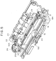
- Fig. 5 is an outside perspective view showing an example of an ink jet recording apparatus (IJRA) on which a recording head obtained by the present invention is mounted as an ink jet head cartridge (hereinafter, abbreviated as IJC).
- IJRA ink jet recording apparatus
- IJC ink jet head cartridge
- reference numeral 20 designates the ink jet head cartridge (IJC) having a group of nozzles for jetting ink in confrontation with the recording surface of a recording paper fed onto a platen 24.
- Numeral 16 designates a carriage HC for holding the IJC 20.
- the carriage 16 is connected to a portion of a drive belt 18 for transmitting the drive force of a drive motor 17 so that it can slide along two guide shafts 19A and 19B disposed in parallel to each other. With this arrangement, the carriage 16 can reciprocatingly move over the entire width of the recording paper.
- Numeral 26 designates a head recovery unit disposed at an end of the moving path of the IJC 20, e.g., a position confronting the home position thereof.
- the IJC 20 is capped by operating the head recovery unit 26 by the drive force of a motor 22 through a power transmission mechanism 23.
- a jet capability recovery processing is performed in such a manner that ink is sucked by a suitable sucking means provided with the head recovery unit 26 or fed under pressure by a suitable pressurizing means provided with an ink feed path to the IJC 20, in association with the capping of the IJC 20 effected by the cap portion 26A of the head recovery unit 26, to forcibly discharge ink from a jet port to thereby remove ink with an increased viscosity in the nozzles.
- the IJC is protected by performing capping upon the completion of recording, and the like.
- Numeral 30 designates a blade as a wiping member formed of silicon rubber and disposed on the side surface of the head recovery unit 26.
- the blade 30 is cantilevered by a blade holding member 30A, operated by the motor 22 and a transmission mechanism 23 in the same way as the head recovery unit 26, and can be engaged with the jet surface of the IJC 20.
- the blade 30 is projected into the moving path of the IJC 20 at a proper timing in the recording operation of the IJC 20 or after the jet capability recovery processing effected by using the head recovery unit 26, to wipe dew drops, wetting, dust and the like on the jet surface of the IJC 20 which are produced as the IJC 20 is moved in operation.
- Fig. 1 is a schematic partial cross sectional view showing the layer arrangement of the heater board of a recording head made by Examples 1 - 23.
- the cross sectional position of the heater board is shown by the cross sectional line X - Y of the schematic partial plan view of Fig. 2
- the heater board is arranged such that a heat accumulation layer 102, heat generating resistance layer 103, electrode layers 104, first protection layer 105, second protection layer 106, and third protection layer 107 are sequentially laminated at the predetermined positions on a substrate 101.
- the heat generating resistance layer 103 between the electrodes serves as a heat generating portion 201.
- the substrate 101 was composed of silicon, and thermally oxidized SiO2 was formed on the substrate 101 to a thickness of 2.0 microns as the heat accumulation layer 102.
- the heat generating resistance layer 103 was spin coated on the heat accumulation layer 102 by using the conditions and materials shown in Table 1.
- metal resinates made by Engelthard Co., Ltd. (trade names are shown in Table 1) were used as an organic resinate for the material of the heat generating resistance layer 103.
- the organic resinate was diluted with chloromethane to provide the material with a predetermined viscosity.
- Al was formed on the heat generating resistance layer 103 to a film thickness of 0.6 micron by vapor deposition and a circuit pattern shown by the dotted line in Fig. 2 was formed by photolithography as the electrode layers 104.
- the heat generating portion 201 was also formed between the electrodes in the size of 30 microns x 150 microns.
- SiO2 was sputtered on the electrode layers 104 to a film thickness of 1.0 micron as the first protection layer 105.
- Ta was sputtered on the first protection layer 105 to a film thickness of 0.5 micron and formed to a bar-shaped pattern as shown by the solid line in Fig. 2 by photolithography as the second protection layer 106.
- heat sensitive polyimide was coated on the second protection layer 106 and formed to a pattern having a shape shown in Fig. 1 as the third protection layer 107.
- the heater board was completed by the above process.
- a predetermined nozzle flow path, ink chamber, ink feed port, ink jet port (40 microns x 40 microns) were formed on the heater board by a usual operation to complete a liquid jet recording head.
- a liquid jet recording head was made by the same way as that of Example 1 except that a heat generating resistance layer 103 was not formed of an organic resinate but formed by sputtering Ta2N to a film thickness of 0.2 micron.
- a liquid jet recording head was made by the same way as that of Example 2 except that a heat generating resistance layer 103 was not formed of an organic resinate but formed by using dispersed ruthenium oxide and glass formed to a thickness of about 2 microns by a printing method and that a first protection layer 105 was formed to a film thickness of 3 microns for an ink shut-off property.
- Bubbling states of ink in response to a recording signal with a driving frequency of 10 Hz - 50 kHz were visually observed for evaluation with respect to the respective recording heads made by Examples 1 - 5 and Comparative Examples 1 - 2.
- the result of the evaluation is shown in Table 2.
- the recording head of Comparative Example 1 has an unstable bubbling state at the driving frequency of 50 kHz.
- the recording head of Comparative Example 2 has an unstable bubbling state at the driving frequency of 10 kHz and a very unstable bubbling state at the driving frequency of 100 Hz or higher.
- the recording heads of Examples 1 - 5 have a stable ink bubbling state even at a high driving frequency because the heat generating resistance layer 103 has a small thermal capacity and thus the first protection layer 105 may be thin.
- the recording heads of Examples 1 - 5 and the recording head of Comparative Example 1 have broken pulses of an order of 108 - 109 and thus they have the same durability against thermal stress. More specifically, even if the heat generating resistance layer is formed by coating, the durability thereof is not inferior to that of a heat generating resistance layer made by a vacuum thin film forming process.
- Table 3 Broken Pulses Example 1 3 x 10⁸ Example 2 5 x 10⁸ Example 3 1 x 10⁹ Example 4 3 x 10⁸ Example 5 2 x 10⁸ Comparative Example 1 3 x 10⁸
- a substrate 101 was composed of silicon, and thermally oxidized SiO2 was formed on the substrate 101 to a thickness of 2.0 microns as a heat accumulation layer 102. Then, HfB2 was sputtered on the heat accumulation layer 102 to a film thickness of 0.1 micron as a heat generating resistance layer 103.
- a layer serving as electrode layers were spin coated on the heat generating resistance layer 103 by using the conditions and materials shown in Table 4. Note, metal resinates made by Engelthard Co., Ltd. (trade names are shown in Table 4) were used as an organic resinate for the material of the layers. Further, in the spin coating, the organic resinate was diluted with chloromethane to provide the material with a predetermined viscosity.
- the layer was formed to a circuit pattern shown by the dotted line of Fig. 2 to make the electrode layers 104.
- a heat generating portion 201 was also formed between the electrodes in the size of 30 microns x 150 microns.
- SiO2 was sputtered on the electrode layers 104 to a film thickness of 1.0 micron as a first protection layer 105.
- Ta was sputtered on the first protection layer 105 to a film thickness of 0.5 micron and formed to a bar-shaped pattern as shown by the solid line in Fig. 2 by photolithography to form a second protection layer 106.
- heat sensitive polyimide was coated on the second protection layer 106 and formed to a pattern having a shape shown in Fig. 1 to form a third protection layer 107.
- a heater board was completed by the above process.
- a predetermined nozzle flow path, ink chamber, ink feed port, ink jet port (40 microns x 40 microns) were formed on the heater board by a usual operation to complete a liquid jet recording head.
- a liquid jet recording head was made by the same way as that of Example 6 except that electrode layers 104 were not formed of an organic resinate but formed to a film thickness of 0.6 micron by vacuum evaporating Al.
- a liquid jet recording head was made by the same way as that of Example 6 except that electrode layers 104 were not formed of an organic resinate but formed by using dispersed Au and glass formed to a thickness of about 2 microns by a printing method and that a first protection layer 105 was formed to a film thickness of 3 microns for an ink shut-off property.
- Bubbling states of ink in response to a recording signal with a driving frequency of 10 Hz - 50 kHz were visually observed for evaluation with respect to the respective recording heads made by Examples 6 - 7 and Comparative Examples 3 - 4.
- the result of the evaluation is shown in Table 5.
- the recording head of Comparative Example 3 has an unstable bubbling state at the driving frequency of 50 kHz.
- the recording head of Comparative Example 4 has an unstable bubbling state at the driving frequency of 10 kHz and a very unstable bubbling state at the driving frequency of 100 Hz or higher.
- the recording heads of Examples 6 - 7 have a stable ink bubbling state even at a high driving frequency because the first protection layer 105 may be thin.
- the recording heads of Examples 6 - 7 and the recording head of Comparative Example 3 have broken pulses of an order of 108 and thus they have the same durability against thermal stress. More specifically, even if the electrode layers are formed by coating, the durability thereof is not inferior to that of electrode layers made by a vacuum thin film forming process.
- a substrate 101 was composed of silicon, and thermally oxidized SiO2 was formed on the substrate 101 to a thickness of 2.0 microns as a heat accumulation layer 102. Then, a heat generating resistance layer 103 was spin coated on the heat accumulation layer 102 by using the conditions and materials shown in Table 7. Note, metal resinates made by Engelthard Co., Ltd. (trade names are shown in Table 7) were used as an organic resinate for the material of the heat generating resistance layer 103. In the spin coating, the organic resinate was diluted with chloromethane to provide the material with a predetermined viscosity.
- An organic resinate material for Al which was obtained by diluting a metal resinate made by Engelthard Co., Ltd. (trade name: A-3808, composed mainly of carboxylate) with chloromethane to a viscosity of 11 cp, was spin coated on the heat generating resistance layer 103 under the coating conditions of a first step; 500 rpm x 5 seconds and a second step; 3000 rpm x 30 seconds. The coated film was baked at a room temperature for 10 minutes, at 120°C for 10 minutes and at 550°C for 10 minutes. Then, an Al thin layer having a final film thickness of 0.7 micron and a sheet resistance of 0.05 ohm/ ⁇ was formed for electrode layers.
- the Al thin film was formed to a circuit pattern shown by the dotted line in Fig. 2 by photolithography to form the electrode layers 104.
- a heat generating portion 201 was also formed between the electrodes in the size of 30 microns x 150 microns.
- SiO2 was sputtered on the electrode layers 104 to a film thickness of 1.0 micron as a first protection layer 105.
- Ta was sputtered on the first protection layer 105 to a film thickness of 0.5 micron and formed to a bar-shaped pattern as shown by the solid line in Fig. 2 by photolithography to form a second protection layer 106.
- heat sensitive polyimide was coated on the second protection layer 106 and formed to a pattern having a shape shown in Fig. 1 to form a third protection layer 107.
- a heater board was completed by the above process.
- a predetermined nozzle flow path, ink chamber, ink feed port, ink jet port (40 microns x 40 microns) were formed on the heater board by a usual operation to complete a liquid jet recording head.
- a liquid jet recording head was made by the same way as that of Example 8 except that a heat generating resistance layer 103 and electrode layers 104 were not formed of an organic resinate but the former was formed by sputtering Ta2N to a film thickness of 0.2 micron and the latter was formed by vacuum evaporating Al to a film thickness of 0.6 micron.
- a liquid jet recording head was made by the same way as that of Example 8 except that a heat generating resistance layer 103 and electrode layers 104 were not formed of an organic resinate but the former was formed by using dispersed ruthenium oxide and glass formed to a thickness of about 2 microns by a printing method and the latter was formed by using dispersed Au and glass formed to a thickness of about 2 microns by a printing method and that a first protection layer 105 was formed to a film thickness of 4 microns for an ink shut-off property.
- Bubbling states of ink in response to a recording signal with a driving frequency of 10 Hz - 50 kHz were visually observed for evaluation with respect to the respective recording heads made by Examples 8 - 12 and Comparative Examples 5 - 6.
- the result of the evaluation is shown in Table 8.
- the recording head of Comparative Example 5 has an unstable bubbling state at the driving frequency of 50 kHz.
- the recording head of Comparative Example 6 has an unstable bubbling state at the driving frequency of 10 kHz and a very unstable bubbling state at the driving frequency of 100 Hz or higher.
- the recording heads of Examples 8 - 12 have a stable ink bubbling state even at a high driving frequency because the heat generating resistance layer 103 has a small heat capacity and thus the first protection layer 105 may be thin.
- the recording heads of Examples 8 - 12 and the recording head of Comparative Example 5 have broken pulses of an order of 108 - 109 and thus they have the same durability against thermal stress. More specifically, even if the heat generating resistance layer and electrode layers are formed by coating, the durability thereof is not inferior to that of a heat generating resistance layer and electrode layers made by a vacuum thin film forming process.
- Table 9 Broken Pulses Example 8 3 x 10⁸ Example 9 5 x 10⁸ Example 10 1 x 10⁹ Example 11 3 x 10⁸ Example 12 2 x 10⁸ Comparative Example 5 3 x 10⁸
- a substrate 101 was composed of silicon, and thermally oxidized SiO2 was formed on the substrate 101 to a thickness of 2.0 microns as a heat accumulation layer 102. Then, HfB2 was sputtered on the heat accumulation layer 102 to a film thickness of 0.2 micron as a heat generating resistance layer 103. Then, Al was vacuum evaporated on the heat generating resistance layer 103 to a thickness of 0.6 micron and formed to a circuit pattern shown by the dotted line in Fig. 2 by photolithography to form electrode layers 104. With the formation of the electrode layers 104, a heat generating portion 201 was also formed in the size of 30 microns x 150 microns.
- a second protection layer (an upper protection layer in contact with ink on a heat acting portion) was formed by spin coating by using the conditions and materials shown in Table 10.
- metal resinates made by Engelthard Co., Ltd. (trade names are shown in Table 10) were used as an organic resinate for the material of the layer.
- the organic resinate was diluted with chloromethane to provide the material with a predetermined viscosity.
- the layer was formed to a bar-shaped pattern shown by the solid line of in Fig. 2 to make it a second protection layer 106.
- heat sensitive polyimide was coated on the second protection layer 106 and formed to a pattern having a shape shown in Fig. 1 to form a third protection layer 107.
- a heater board was completed by the above process.
- a predetermined nozzle flow path, ink chamber, ink feed port, ink jet port (40 microns x 40 microns) were formed on the heater board by a usual operation to complete a liquid jet recording head.
- a liquid jet recording head was made by the same way as that of Example 13 except that a second protection layer 106 was not formed of an organic resinate but formed to a film thickness of 0.5 micron by sputtering Ta.
- a liquid jet recording head was made by the same way as that of Example 13 except that a second protection layer 106 was not formed of an organic resinate but formed to a thickness of about 2 microns by a printing method by using dispersed Ta and glass.
- Bubbling states of ink in response to a recording signal with a driving frequency of 10 Hz - 50 kHz were visually observed for evaluation with respect to the respective recording heads made by Examples 13 - 17 and Comparative Examples 7 - 8.
- the result of the evaluation is shown in Table 11.
- the recording head of Comparative Example 7 has an unstable bubbling state at the driving frequency of 50 kHz.
- the recording head of Comparative Example 8 has an unstable bubbling state at the driving frequency of 10 kHz and a very unstable bubbling state at the driving frequency of 100 Hz or higher.
- the recording heads of Examples 13 - 17 have a stable ink bubbling state even at a high driving frequency because the second protection layer 106 has a large heat transfer coefficient and is thin.
- the result of the evaluaiton is shown in Table 12.
- the recording heads of Examples 13 - 17 and the recording head of Comparative Example 7 have no broken segment even at 1 x 10⁹ and thus they have the same durability against jet operation. More specifically, even if the upper protection layer is formed by coating, the durability thereof is not inferior to that of an upper protection layer made by a vacuum thin film forming process.
- Table 12 Number of Broken Segments Number of Pulses 1 x 10⁸ 3 x 10⁸ 5 x 10⁸ 1 x 10⁹ Example 13 0 0 0 0 Example 14 0 0 0 0 Example 15 0 0 0 0 Example 16 0 0 0 0 Example 17 0 0 0 0 Comparative Example 7 0 0 0 0 0 0
- a substrate 101 was composed of silicon, and thermally oxidized SiO2 was formed on the substrate 101 to a thickness of 2.0 microns as a heat accumulation layer 102. Then, a heat generating resistance layer 103 was spin coated on the heat accumulation layer 102 by using the conditions and materials shown in Table 13. Note, metal resinates made by Engelthard Co., Ltd. (trade names are shown in Table 13) were used as an organic resinate for the material of the heat generating resistance layer 103. In the spin coating, the organic resinate was diluted with chloromethane to provide the material with a predetermined viscosity.
- An organic resinate material for Al which was obtained by diluting a metal resinate made by Engelthard Co., Ltd. (trade name: A-3808, composed mainly of carboxylate) with chloromethane to a viscosity of 11 cp, was spin coated on the heat generating resistance layer 103 under the coating conditions of a first step; 500 rpm x 5 seconds and a second step; 3000 rpm x 30 seconds. The coated film was baked at a room temperature for 10 minutes, at 120°C for 10 minutes and at 550°C for 10 minutes. Then, an Al thin layer having a final film thickness of 0.7 micron and a sheet resistance of 0.05 ohm/ ⁇ was formed for electrode layers.
- the Al thin film was formed to a circuit pattern shown by the dotted line in Fig. 2 by photolithography to form the electrode layers 104.
- a heat generating portion 201 was also formed between electrodes in the size of 30 microns x 150 microns.
- a second protection layer (an upper protection layer in contact with ink on a heat acting portion) was formed by spin coating by using the conditions and materials shown in Table 13.
- metal resinates made by Engelthard Co., Ltd. (trade names are shown in Table 13) were used as an organic resinate for the material of the layer.
- the organic resinate was diluted with chloromethane to provide the material with a predetermined viscosity.
- the layer was formed to a bar-shaped pattern shown by the solid line of in Fig. 2 to make it a second protection layer 106.
- heat sensitive polyimide was coated on the second protection layer 106 and formed to a pattern having a shape shown in Fig. 1 to form a third protection layer 107.
- a heater board was completed by the above process.
- a predetermined nozzle flow path, ink chamber, ink feed port, ink jet port (40 microns x 40 microns) were formed on the heater board by a usual operation to complete a liquid jet recording head.
- a liquid jet recording head was made by the same way as that of Example 18 except that a heat generating resistance layer 103, electrode layers 104 and a second protection layer were not formed of an organic resinate but the heat generating resistance layer 103 was formed by sputtering Ta2N to a film thickness of 0.2 micron, the electrode layers 104 were formed by vacuum evaporating Al to a film thickness of 0.6 micron, and the second protection layer 106 was formed by sputtering Ta to a film thickness of 0.5 micron.
- a liquid jet recording head was made by the same way as that of Example 18 except that a heat generating resistance layer 103, electrode layers 104 and a second protection layer 106 were not formed of an organic resinate but the heat generating resistance layer 103 was formed by using dispersed ruthenium oxide and glass formed to a thickness of about 2 microns by a printing method, the electrode layers 104 were formed by using dispersed Au and glass formed to a thickness of about 2 microns by a printing method, and the second protection layer 106 was formed by using dispersed Ta and glass formed to a thickness of about 2 microns by a printing method and that a first protection layer 105 was formed to a film thickness of 4 microns for an ink shut-off property.
- Bubbling states of ink in response to a recording signal with a driving frequency of 10 Hz - 50 kHz were visually observed for evaluation with respect to the respective recording heads made by Examples 18 - 23 and Comparative Examples 9 - 10.
- the result of the evaluation is shown in Table 15.
- the recording head of Comparative Example 9 has an unstable bubbling state at the driving frequency of 50 kHz.
- the recording head of Comparative Example 10 has an unstable bubbling state at the driving frequency of 10 kHz and a very unstable bubbling state at the driving frequency of 100 Hz or higher.
- the recording heads of Examples 18 - 23 have a stable ink bubbling state even at a high driving frequency because the heat generating resistance layer 103 has a small heat capacity, the second protection layer 106 has a large heat transfer coefficient and a thin film thickness and thus the first protection layer 105 may be thin.
- the recording heads of Examples 18 - 23 and the recording head of Comparative Example 9 have no broken segment even at 1 x 10⁹ and thus they have the same durability against jet operation. More specifically, even if the upper protection layer and the like are formed by coating, the durability thereof is not inferior to that of an upper protection layer and the like made by a vacuum thin film forming process.
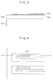
- Fig. 3 is a schematic partial cross sectional view showing the layer arrangement of the heater board of a recording head made by Examples 24 - 35.
- the cross sectional position of the heater board is shown by the cross sectional line X - Y of the schematic partial plan view of Fig. 4.
- the heater board is arranged such that a heat accumulation layer 102, heat generating resistance layer 103 and electrode layers 104 are sequentially laminated at the predetermined positions on a substrate 101.
- the heat generating resistance layer 103 between the electrodes serves as a heat generating portion 201.
- the substrate 101 was composed of silicon, and thermally oxidized SiO2 was formed on the substrate 101 to a thickness of 2.0 microns as the heat accumulation layer 102.
- the heat generating resistance layer 103 was spin coated on the heat accumulation layer 102 by using the conditions and materials shown in Table 17.
- metal resinates made by Engelthard Co., Ltd. (trade names are shown in Table 17) were used as an organic resinate for the material of the heat generating resistance layer 103.
- the organic resinate was diluted with chloromethane to provide the material with a predetermined viscosity.
- a predetermined nozzle flow path, ink chamber, ink feed port, ink jet port (40 microns x 40 microns) were formed on the heater board by a usual operation to complete a liquid jet recording head.
- a liquid jet recording head was made by the same way as that of Example 24 except that a heat generating resistance layer 103 was not formed of an organic resinate but formed by sputtering Al-Ta-Ir to a film thickness of 0.2 micron.
- a liquid jet recording head was made by the same way as that of Example 24 except that a heat generating resistance layer 103 was not formed of an organic resinate but formed by using dispersed iridium oxide and glass formed to a thickness of about 2 microns by a printing method.
- Bubbling states of ink in response to a recording signal with a driving frequency of 10 Hz - 50 kHz were visually observed for evaluation with respect to the respective recording heads made by Examples 24 - 28 and Comparative Examples 11 - 12.
- the result of the evaluation is shown in Table 18.
- the recording head of Comparative Example 11 has an unstable bubbling state at the driving frequency of 50 kHz.
- the recording head of Comparative Example 12 has an unstable bubbling state at the driving frequency of 10 kHz and a very unstable bubbling state at the driving frequency of 100 Hz or higher.
- the recording heads of Examples 24 - 28 have a stable ink bubbling state even at a high driving frequency because the heat generating resistance layer 103 has a small thermal capacity.
- the recording heads of Examples 24 - 28 and the recording head of Comparative Example 11 have no broken segment even at 1 x 10⁹ and thus they have the same durability against jet operation. More specifically, even if the heat generating resistance layer is formed by coating, the durability thereof is not inferior to that of a heat generating resistance layer made by a vacuum thin film forming process.
- Table 19 Number of Broken Segments Number of Pulses 1 x 10⁸ 3 x 10⁸ 5 x 10⁸ 1 x 10⁹ Example 24 0 0 0 0 Example 25 0 0 0 0 Example 26 0 0 0 0 Example 27 0 0 0 0 Example 28 0 0 0 0 Comparative Example 11 0 0 0 0 0 0
- a substrate 101 was composed of silicon, and thermally oxidized SiO2 was formed on the substrate 101 to a thickness of 2.0 microns as a heat accumulation layer 102. Then, HfB2 was sputtered on the heat accumulation layer 102 to a film thickness of 0.1 micron as a heat generating resistance layer 103.
- a layer serving as electrode layers was spin coated on the heat generating resistance layer 103 by using the conditions and materials shown in Table 20. Note, metal resinates made by Engelthard Co., Ltd. (trade names are shown in Table 20) were used as an organic resinate for the material of the layers. Further, in the spin coating, the organic resinate was diluted with chloromethane to provide the material with a predetermined viscosity.
- the layer was formed to a circuit pattern shown in Fig. 4 to make the electrode layers 104.
- a heat generating portion 201 was also formed between the electrodes in the size of 30 microns x 150 microns.
- a heater board was completed by the above process.
- a predetermined nozzle flow path, ink chamber, ink feed port, ink jet port (40 microns x 40 microns) were formed on the heater board by a usual operation to complete a liquid jet recording head.
- a liquid jet recording head was made by the same way as that of Example 29 except that electrode layers 104 were not formed of an organic resinate but formed to a film thickness of 0.6 micron by vacuum evaporating Au.
- a liquid jet recording nead was made by the same way as that of Example 29 except that electrode layers 104 were not formed of an organic resinate but formed by using dispersed Au and glass formed to a thickness of about 2 microns by a printing method.
- the recording heads of Examples 29 - 30 and the recording head of Comparative Example 13 have no broken segment even at 1 x 10⁹ and thus they have the same durability against jet operation. More specifically, even if the heat generating resistance layer is formed by coating, the durability thereof is not inferior to that of a heat generating resistance layer made by a vacuum thin film forming process. Further, it is shown that Comparative Example 14 using dispersed Au and glass has inferior durability against jet operation. Table 21 Number of Broken Segments Number of Pulses 1 x 10⁸ 3 x 10⁸ 5 x 10⁸ 1 x 10⁹ Example 29 0 0 0 0 Example 30 0 0 0 0 Comparative Example 13 0 0 0 0 Comparative Example 14 0 0 15 155
- a substrate 101 was composed of silicon, and thermally oxidized SiO2 was formed on the substrate 101 to a thickness of 2.0 microns as a heat accumulation layer 102. Then, a heat generating resistance layer 103 was spin coated on the heat accumulation layer 102 by using the conditions and materials shown in Table 22. Note, metal resinates made by Engelthard Co., Ltd. (trade names are shown in Table 22) were used as an organic resinate for the material of the heat generating resistance layer 103. In the spin coating, the organic resinate was diluted with chloromethane to provide the material with a predetermined viscosity.
- An electrochemically stable organic resinate material for Au which was obtained by diluting a metal resinate made by Engelthard Co., Ltd. (trade name: A-1118, composed mainly of carboxylate) with chloromethane to a viscosity of 15 cp, was spin coated on the heat generating resistance layer 103 under the coating conditions of a first step; 500 rpm x 5 seconds and a second step; 3000 rpm x 30 seconds. The coated film was baked at a room temperature for 10 minutes, at 120°C for 10 minutes and at 850°C for 10 minutes. Then, an Au thin film having a final thickness of 1.0 micron and a sheet resistance of 0.07 ohm/ ⁇ was formed for electrode layers.
- the Au thin film was formed to a circuit pattern shown in Fig. 4 by photolithography to form the electrode layers 104.
- a heat generating portion 201 was also formed between electrodes in the size of 30 microns x 150 microns.
- a heater board was completed by the above process.
- a predetermined nozzle flow path, ink chamber, ink feed port, ink jet port (40 microns x 40 microns) were formed on the heater board by a usual operation to complete a liquid jet recording head.
- a liquid jet recording head was made by the same way as that of Example 31 except that a heat generating resistance layer 103 and electrode layers 104 were not formed of an organic resinate but the former was formed by sputtering Al-Ta-Ir to a film thickness of 0.2 micron and the latter was formed by vacuum evaporating Au to a film thickness of 0.5 micron.
- a liquid jet recording head was made by the same way as that of Example 31 except that a heat generating resistance layer 103 and electrode layers 104 were not formed of an organic resinate but the former was formed by using dispersed iridium oxide, tantalum oxide and glass formed to a thickness of about 2 microns by a printing method and the latter was formed by using dispersed Au and glass formed to a thickness of about 2 microns by a printing method.
- a liquid jet recording head was made by the same way as that of Example 31 except that a heat generating resistance layer 103 and electrode layers 104 were not formed of an organic resinate but the former was formed by sputtering Al-Ta-Ir to a film thickness of 0.2 micron and the latter was formed by using dispersed Au and glass formed to a thickness of about 2 microns by a printing method.
- Bubbling states of ink in response to a recording signal with a driving frequency of 10 Hz - 50 kHz were visually observed for evaluation with respect to the respective recording heads made by Examples 31 - 35 and Comparative Examples 15 - 17.
- the result of the evaluation is shown in Table 23.
- the recording head of Comparative Example 16 has an unstable bubbling state at the driving frequency of 10 kH and a very unstable bubbling state at the driving frequency of 100 Hz or higher.
- the recording heads of Examples 31 - 35 have a stable ink bubbling state even at a high driving frequency because the heat generating resistance layer 103 has a small heat capacity, the second protection layer has a large heat transfer coefficient and a thin film thickness, and thus the first protection layer 105 may be thin.
- the recording heads of Examples 31 - 35 and the recording head of Comparative Example 15 have no broken segment even at 1 x 10⁹ and thus they have the same durability against jet operation. More specifically, even if the heat generating resistance layer is formed by coating, the durability thereof is not inferior to that of a heat generating resistance layer made by a vacuum thin film forming process. Further, it is shown that Comparative Example 16 using dispersed Au and glass has inferior durability against jet operation.
- the present invention achieves an excellent advantage particularly in the ink jet recording type recording head and recording apparatus which make recording by forming flying droplets by making use of thermal energy among various ink jet recording systems.
- a typical arrangement and principle of the ink jet recording system are disclosed, for example, in the specifications of United States Patents Nos. 4,723,129 and 4,740,796, and the present invention is preferably executed by using the basic principle of these patents.
- This recording system is applicable to any of so-called on-demand type and continuous type recording systems.
- thermal energy is generated by imposing at least one drive signal on an electrothermal converter disposed in correspondence to a sheet or liquid path in which liquid (ink) is held in order to abruptly increase the temperature of the liquid (ink) so that a film boiling phenomenon exceeding a nuclear boiling phenomenon is arisen in the ink (liquid) in correspondence to recorded data and thus the film boiling is caused on the heat acting surface of a recording head.
- bubbles can be formed in such a manner that each bubble corresponds to each drive signal imposed on the electrothermal converter from the liquid (ink) as described above, this recording system is particularly effective to an on-demand type recording method.
- the liquid (ink) is jetted from a jet port by the growth/contraction of the bubbles to form at least single droplet.
- the present invention also includes the arrangement of a recording head having a heat acting portion disposed in a bent region as shown in the specifications of United States Patents Nos. 4,558,333 and 4,459,600, in addition to the arrangement in which an ink jet port, liquid flow path and electrothermal converter are combined (linear or right angle liquid path) as disclosed in the above respective specifications.
- the present invention is effectively applied to the arrangement disclosed in Japanese Patent Application Laid-Open No. 59-123670 in which a common slit is provided as a jet port for a plurality of electrothermal converters and the arrangement disclosed in Japanese Patent Application Laid-Open No. 59-138461 in which an opening for absorbing the pressure wave of thermal energy is provided in correspondence to a jet port.
- the present invention is effectively applied to a full line type recording head having a length corresponding to the maximum width of a recording medium to which a recording apparatus can make recording.
- This full line head may be arranged to a full line by combining a plurality of the recording heads disclosed in the above specifications or an integrally formed single full line recording head.
- the present invention is also effectively applied to the cases in which a replaceable tip type recording head is used which, when mounted on the main body of an apparatus, is electrically connected to the main body or supplied with ink therefrom or in which a cartridge type recording head integrally provided with a recording head itself is used.
- the recording apparatus of the present invention is preferably added with a recovery means for a recording head, preliminary auxiliary means and the like to further stabilize the recording apparatus of the present invention.
- the recording head may be added with a capping means, cleaning means, pressurizing or sucking means, electrothermal converter, heating element other than the electrothermal converter, preliminary heating means composed of the combination thereof, and means for effecting a preliminary jetting mode for performing jetting other than recording in order to stably execute recording.
- the present invention is very effectively applied not only to a recording apparatus having a recording mode only for a main color such as a black color or full colors composed of mixed colors, although a recording head may be arranged integrally or by the combination of a plurality of recording heads.
- the present invention may use any ink material solidified or softened at a room temperature. Since the aforesaid ink jet apparatus generally adjusts the temperature of an ink material itself within the range from 30°C to 70°C so that the ink material has a viscosity within a stable jet range, any ink material may be employed so long as it is in a liquid state when a recording signal being used is applied.
- an ink material that can positively prevent an excessive temperature rise of a head and the ink material caused by thermal energy by using the energy to change the state of the ink material from a solid state to a liquid state or an ink material that solidifies when left unused in order to prevent the evaporation thereof.
- an ink material which has a property to be liquefied first by the application of thermal energy such as the one which is liquefied and jetted as liquid ink by the application of thermal energy corresponding to a recording signal or the one which has been started to be solidified when it reaches a recording medium.
- ink materials may confront an electrothermal converter in the state that they are held in the recessed portions or through holes of a porous sheet as a liquid or solid material, as disclosed in Japanese Patent Applications Laid-Open Nos. 54-56847 and 60-71260.
- the execution of the aforesaid film boiling system is most effective to the aforesaid respective ink materials.
- a liquid jet recording apparatus including a heat acting portion communicating with a liquid jetting orifice for applying thermal energy to a liquid to form a bubble, an electrothermal converter for generating the thermal energy, a heat generating resistance layer contained in the electrothermal converter, and electrode layers for imposing a voltage to the heat generating resistance layer contained in the electrothermal converter, wherein the heat generating resistance layer is composed mainly of an organic resinate.
Abstract
Description
- The present invention relates to a liquid jet recording head for jetting liquid from an orifice and forming droplets and a method of manufacturing the same.
- Conventionally, there is known a liquid jet recording method (ink jet recording method) for jetting liquid from an orifice and executing recording by a droplet thereof. For example, Japanese Laid-Open Patent Application No. 54-51837 discloses a type of a liquid jet recording method by which power for jetting droplets is obtained by applying thermal energy to liquid. This kind of the recording method is characterized in that liquid to which the action of thermal energy is applied is heated to produce bubbles, droplets are formed from the orifice at the extreme end of a recording head by an acting force due to the production of the bubbles, and the droplets are deposited on a recording member for recording information.
- The liquid jet portion of a recording head applied to this recording method includes an orifice for jetting liquid and a liquid flow path communicating with the orifice. A portion of the liquid flow path is composed as a heat acting portion where thermal energy for jetting droplets is acted to the liquid. Further, the recording head includes a heat generating resistance layer as a thermal converter serving as a thermal energy generating means and an upper protection layer for protecting the heat generating resistance layer from ink.
- In order to effectively bubble ink in this type of the recording method, a bubbling surface must be heated to about 300°C at very short pulse intervals and the temperature thereof must be returned to a room temperature in an order of microsecond. For this purpose, the heat generating resistance layer itself must have a reduced thermal capacity. Further, a thermal resistance between the heat generating resistance layer and the bubbling surface (more specifically, the thermal resistance of electrodes and the upper protection layer) must be also reduced because of the same reason. On the other hand, since the heat generating resistance layer, electrodes and upper protection layer are usually formed by lamination, if the heat generating resistance layer and electrodes have an excessively thin width, the step of these portions is relatively increased. When the stepped portion is increased, the quality of the film of the upper protection layer covering these portions is deteriorated and thus a problem of the electric erosion and the like of the electrodes and heat generating resistance layer arises.
- Therefore, it is preferable to make a film thickness thin as a means for reducing the thermal capacity of the heat generating resistance layer. Further, a thermal resistance can be reduced by making the film thickness of the electrodes and upper protection layer. A specific film thickness is preferably 0.1 to 1 micron. Conventionally, when an inorganic material used for the heat generating resistance layer, electrodes and protection layer is formed to such a film thickness, the film is formed by using a vacuum process such as a vacuum vapor deposition and sputtering method. The vacuum process, however, needs a large manufacturing apparatus as well as the productivity thereof is not so good because severe environmental conditions are required for the formation of a good thin film. Further, this process is not always preferable from the view point of cost because the manufacturing apparatus is expensive.
- Taking the above problem into consideration, the inventor has discovered a completely novel method as a result of a zealous study. The present invention provides a method of manufacturing a liquid jet recording head by which a thin film composed of an inorganic material can be formed by a conventionally used method such as a printing method and coating method executed in the atmosphere, the method being able to be relatively easily achieved, a head made by the manufacturing method, and a liquid jet recording apparatus including the head and a member for mounting the head. A main object of the present invention is to provide a liquid jet recording apparatus including a heat acting portion communicating with a liquid jetting orifice for applying thermal energy to a liquid to form a bubble, an electrothermal converter for generating the thermal energy, a heat generating resistance layer contained in the electrothermal converter, and electrode layers for imposing a voltage to the heat generating resistance layer contained in the electrothermal converter, wherein the heat generating resistance layer is composed mainly of an organic resinate.
- The organic resinate used in the present invention generally includes carboxylate, carboxylic acid ester, alkoxide, rosin ester, polycyclic organic compound, siloxanes, bolic acid compound, and the like.
- According to the present invention, since a desired thin film can be easily formed in the atmosphere, a highly reliable liquid jet recording head of low cost with high productivity can be provided. Further, the liquid jet recording head can stably jet liquid even if it is driven at a high frequency because a thick film such as that formed of a dispersed material of inorganic material and glass used in a conventional printing method and coating method is not formed and the surface property of a film is not degraded.
- Further, the inventors have discovered that the present invention has an advantage completely different from the aforesaid advantage in addition to it. That is, according to the present invention, defective portions such as pin holes and the like of a thin film conventionally found in a sputtering method and the like are greatly reduced. This is supposed to be caused by the fact that the thin film is not liable to be porous because it is not affected by a high voltage imposed thereon and severe environmental conditions. This advantage can further reduce the electric erosion of a heat generating resistance layer and electrode by ink.
- As described above, the present invention is epock-making in that when a thin film is formed of an inorganic material, the film is made as fine as a film composed of an organic material and the film can be formed easily.
-
- Fig. 1 is a schematic partial cross sectional view showing the layer arrangement of the heater board of a recording head made to Examples 1 - 23;
- Fig. 2 is a schematic plan view showing the position and the like of the cross sectional line X - Y in the cross sectional view in Fig. 1;
- Fig. 3 is a schematic partial cross sectional view showing the layer arrangement of the heater board of a recording head made by Examples 24 - 35;
- Fig. 4 is a schematic plan view showing the position and the like of the cross sectional line X - Y in the cross sectional view in Fig. 3; and
- Fig. 5 is an outside perspective view showing an example of an ink jet recording apparatus to which a recording head of the present invention is mounted as an ink jet head cartridge.
- The present invention will be described below in more detail.
- Although a property required to a heat generating resistance layer is a small thermal capacity as described above, this property relates to the bubbling stability of bubbles, and in particular an increase in a driving frequency increases the effect of the bubbling stability, which leads to unstable bubbling and jet operation in its turn. Further, as a recent tendency, as a recording head has an increased length and an apparatus has a reduced size, a heat generating portion is required to save power consumption, and thus the resistance of the heat generating resistance layer is increased.
- A material satisfying these properties includes ZrB₂, TiB₂, Ta₂Si, Ti₂Si, TaAl and the like. The present invention forms the heat generating resistance layer composed mainly of an organic resinate containing these inorganic materials so that a thin film having substantially the same property as that of a thin film formed by a vacuum process such as a conventional sputtering method and the like can be formed. Further, since the thin film can be formed in the atmosphere, a recording head which is more reliable and more durable than a conventional recording head can be made.
- Although a metal such as Au, Al having a high conductivity has been used as electrodes, the present invention can form a thin film having substantially the same property as that of a thin film conventionally formed by the vacuum process such as the sputtering method and the like by forming the electrodes mainly of an organic resinate containing these metals.
- Further, in the case of a liquid jet recording head of a type in which the heat generating resistance layer and electrodes come into direct contact with ink, a material excellent in electrochemical stability must be used in addition to the aforesaid respective characteristics. For example, a material such as WNi, ZrCr, TaIr, TaFe, ZrNi is used as the heat generating resistance layer, and a material such as Au, Pt is used as the electrodes. The present invention can provide a highly reliable liquid jet recording apparatus by forming the heat generating resistance layer and electrodes formed mainly of an organic resinate containing these respective materials.
- Moreover, since the thin film formed by the present invention includes a reduced number of defective portions such as pin holes, a resistance value is not partially concentrated, and thus the reliability of the heat generating resistance layer and electrodes can be greatly improved.
- Although the present invention can exhibit a sufficient advantage even if the heat generating resistance layer or the electrodes are independently used, when they are used in combination, the advantage thereof can be further improved in multiplication.
- On the other hand, a protection layer is composed of a multi-layer including a conventional insulation layer, liquid-resistant layer, and cavitation-resistant layer provided for each function. In the present invention, however, electric erosion caused from defective portions such as pin holes, which has been conventionally a particular problem, can be securely prevented by forming at least the portion of the protection layer in contact with ink mainly of an organic resinate containing an inorganic material conventionally used for the protection layer. In particular, since the cavitation-resistant layer coming into contact wtih the ink as a heat acting portion must be composed of a material excellent in mechanical shock resistance, a thermally and chemically stable metal material such as Ta, W, Pt or the like is used, and a protection layer having a stable resistance to mechanical shock even at a high temperature can be formed by forming the cavitation-resistant layer mainly of an organic resinate containing these materials.
- Needless to say, the advantage of the present application can be further improved by using the aforesaid heat generating resistance layer and electrodes together in addition to the protection layer.
- According to the present invention, a cost for forming the thin film, when compared with a cost for forming the same by a vacuum film forming method, can be greatly reduced to about 1/8 with respect to the heat generating resistance layer, about 1/10 with respect to the electrodes, and 1/12 with respect to the protection layer. Further, the thin film can be formed at a lower cost as compared with the case in which the film is formed of a dispersed organic material and glass used in a conventional printing method, coating method and the like, and the reliability of the thus formed film is improved.
- The thin film composed mainly of the organic resinate according to the present invention is formed in such a process that a paste composed mainly of the organic resinate is coated on a substrate by a coating method, printing method or the like and then dried to remove the solvent contained in the paste and further baked in an atmosphere containing a sufficient amount of oxygen at 350°C or higher or preferably at 600°C or higher to remove a resin component contained in the paste.
- Fig. 5 is an outside perspective view showing an example of an ink jet recording apparatus (IJRA) on which a recording head obtained by the present invention is mounted as an ink jet head cartridge (hereinafter, abbreviated as IJC).
- In Fig. 5,
reference numeral 20 designates the ink jet head cartridge (IJC) having a group of nozzles for jetting ink in confrontation with the recording surface of a recording paper fed onto aplaten 24. Numeral 16 designates a carriage HC for holding the IJC 20. Thecarriage 16 is connected to a portion of adrive belt 18 for transmitting the drive force of adrive motor 17 so that it can slide along twoguide shafts 19A and 19B disposed in parallel to each other. With this arrangement, thecarriage 16 can reciprocatingly move over the entire width of the recording paper. - Numeral 26 designates a head recovery unit disposed at an end of the moving path of the IJC 20, e.g., a position confronting the home position thereof. The IJC 20 is capped by operating the
head recovery unit 26 by the drive force of amotor 22 through apower transmission mechanism 23. A jet capability recovery processing is performed in such a manner that ink is sucked by a suitable sucking means provided with thehead recovery unit 26 or fed under pressure by a suitable pressurizing means provided with an ink feed path to theIJC 20, in association with the capping of theIJC 20 effected by thecap portion 26A of thehead recovery unit 26, to forcibly discharge ink from a jet port to thereby remove ink with an increased viscosity in the nozzles. In addition, the IJC is protected by performing capping upon the completion of recording, and the like. -
Numeral 30 designates a blade as a wiping member formed of silicon rubber and disposed on the side surface of thehead recovery unit 26. Theblade 30 is cantilevered by ablade holding member 30A, operated by themotor 22 and atransmission mechanism 23 in the same way as thehead recovery unit 26, and can be engaged with the jet surface of theIJC 20. With this arrangement, theblade 30 is projected into the moving path of theIJC 20 at a proper timing in the recording operation of theIJC 20 or after the jet capability recovery processing effected by using thehead recovery unit 26, to wipe dew drops, wetting, dust and the like on the jet surface of theIJC 20 which are produced as theIJC 20 is moved in operation. - The present invention will be described below in detail with reference to examples.
- Fig. 1 is a schematic partial cross sectional view showing the layer arrangement of the heater board of a recording head made by Examples 1 - 23. The cross sectional position of the heater board is shown by the cross sectional line X - Y of the schematic partial plan view of Fig. 2 In Fig. 1, the heater board is arranged such that a
heat accumulation layer 102, heat generatingresistance layer 103, electrode layers 104,first protection layer 105,second protection layer 106, andthird protection layer 107 are sequentially laminated at the predetermined positions on asubstrate 101. The heat generatingresistance layer 103 between the electrodes serves as aheat generating portion 201. - First, the
substrate 101 was composed of silicon, and thermally oxidized SiO₂ was formed on thesubstrate 101 to a thickness of 2.0 microns as theheat accumulation layer 102. Then, the heat generatingresistance layer 103 was spin coated on theheat accumulation layer 102 by using the conditions and materials shown in Table 1. Note, metal resinates made by Engelthard Co., Ltd. (trade names are shown in Table 1) were used as an organic resinate for the material of the heat generatingresistance layer 103. In the spin coating, the organic resinate was diluted with chloromethane to provide the material with a predetermined viscosity. - Next, Al was formed on the heat generating
resistance layer 103 to a film thickness of 0.6 micron by vapor deposition and a circuit pattern shown by the dotted line in Fig. 2 was formed by photolithography as the electrode layers 104. In addition, with the formation of the electrode layers 104, theheat generating portion 201 was also formed between the electrodes in the size of 30 microns x 150 microns. Then, SiO₂ was sputtered on the electrode layers 104 to a film thickness of 1.0 micron as thefirst protection layer 105. Further, Ta was sputtered on thefirst protection layer 105 to a film thickness of 0.5 micron and formed to a bar-shaped pattern as shown by the solid line in Fig. 2 by photolithography as thesecond protection layer 106. Further, heat sensitive polyimide was coated on thesecond protection layer 106 and formed to a pattern having a shape shown in Fig. 1 as thethird protection layer 107. The heater board was completed by the above process. - Further, a predetermined nozzle flow path, ink chamber, ink feed port, ink jet port (40 microns x 40 microns) were formed on the heater board by a usual operation to complete a liquid jet recording head.
- A liquid jet recording head was made by the same way as that of Example 1 except that a heat generating
resistance layer 103 was not formed of an organic resinate but formed by sputtering Ta₂N to a film thickness of 0.2 micron. - A liquid jet recording head was made by the same way as that of Example 2 except that a heat generating
resistance layer 103 was not formed of an organic resinate but formed by using dispersed ruthenium oxide and glass formed to a thickness of about 2 microns by a printing method and that afirst protection layer 105 was formed to a film thickness of 3 microns for an ink shut-off property.

- Bubbling states of ink in response to a recording signal with a driving frequency of 10 Hz - 50 kHz were visually observed for evaluation with respect to the respective recording heads made by Examples 1 - 5 and Comparative Examples 1 - 2. The result of the evaluation is shown in Table 2.
- As shown in Table 2, the recording head of Comparative Example 1 has an unstable bubbling state at the driving frequency of 50 kHz. The recording head of Comparative Example 2 has an unstable bubbling state at the driving frequency of 10 kHz and a very unstable bubbling state at the driving frequency of 100 Hz or higher. On the other hand, the recording heads of Examples 1 - 5 have a stable ink bubbling state even at a high driving frequency because the heat generating
resistance layer 103 has a small thermal capacity and thus thefirst protection layer 105 may be thin.Table 2 Driving Frequency 10Hz 100Hz 500Hz 1kHz 5kHz 10kHz 50kHz Example 1 o o o o o o △ Example 2 o o o o o o △ Example 3 o o o o o o △ Example 4 o o o o o o △ Example 5 o o o o o o △ Comparative Example 1 o o o o o o △ Comparative Example 2 △ X X X X X X o normal bubbling
△ unstable bubbling
X very unstable bubbling - A recording signal was imposed on the respective recording heads made by Examples 1 - 5 and Comparative Example 1 under the conditions of driving frequency = 5.0 kHz, rectangular pulse width = 10 microseconds, driving voltage = bubbling voltage x 1.4 and durability against thermal stress was evaluated by the broken pulses thereof. The result of the evaluation is shown in Table 3.
- As shown in Table 3, the recording heads of Examples 1 - 5 and the recording head of Comparative Example 1 have broken pulses of an order of 10⁸ - 10⁹ and thus they have the same durability against thermal stress. More specifically, even if the heat generating resistance layer is formed by coating, the durability thereof is not inferior to that of a heat generating resistance layer made by a vacuum thin film forming process.
Table 3 Broken Pulses Example 1 3 x 10⁸ Example 2 5 x 10⁸ Example 3 1 x 10⁹ Example 4 3 x 10⁸ Example 5 2 x 10⁸ Comparative Example 1 3 x 10⁸ - A
substrate 101 was composed of silicon, and thermally oxidized SiO₂ was formed on thesubstrate 101 to a thickness of 2.0 microns as aheat accumulation layer 102. Then, HfB₂ was sputtered on theheat accumulation layer 102 to a film thickness of 0.1 micron as a heat generatingresistance layer 103. A layer serving as electrode layers were spin coated on the heat generatingresistance layer 103 by using the conditions and materials shown in Table 4. Note, metal resinates made by Engelthard Co., Ltd. (trade names are shown in Table 4) were used as an organic resinate for the material of the layers. Further, in the spin coating, the organic resinate was diluted with chloromethane to provide the material with a predetermined viscosity. The layer was formed to a circuit pattern shown by the dotted line of Fig. 2 to make the electrode layers 104. In addition, with the formation of the electrode layers 104, aheat generating portion 201 was also formed between the electrodes in the size of 30 microns x 150 microns. Then, SiO₂ was sputtered on the electrode layers 104 to a film thickness of 1.0 micron as afirst protection layer 105. Further, Ta was sputtered on thefirst protection layer 105 to a film thickness of 0.5 micron and formed to a bar-shaped pattern as shown by the solid line in Fig. 2 by photolithography to form asecond protection layer 106. Further, heat sensitive polyimide was coated on thesecond protection layer 106 and formed to a pattern having a shape shown in Fig. 1 to form athird protection layer 107. A heater board was completed by the above process. - Further, a predetermined nozzle flow path, ink chamber, ink feed port, ink jet port (40 microns x 40 microns) were formed on the heater board by a usual operation to complete a liquid jet recording head.
- A liquid jet recording head was made by the same way as that of Example 6 except that electrode layers 104 were not formed of an organic resinate but formed to a film thickness of 0.6 micron by vacuum evaporating Al.
- A liquid jet recording head was made by the same way as that of Example 6 except that electrode layers 104 were not formed of an organic resinate but formed by using dispersed Au and glass formed to a thickness of about 2 microns by a printing method and that a
first protection layer 105 was formed to a film thickness of 3 microns for an ink shut-off property.
- Bubbling states of ink in response to a recording signal with a driving frequency of 10 Hz - 50 kHz were visually observed for evaluation with respect to the respective recording heads made by Examples 6 - 7 and Comparative Examples 3 - 4. The result of the evaluation is shown in Table 5.
- As shown in Table 5, the recording head of Comparative Example 3 has an unstable bubbling state at the driving frequency of 50 kHz. The recording head of Comparative Example 4 has an unstable bubbling state at the driving frequency of 10 kHz and a very unstable bubbling state at the driving frequency of 100 Hz or higher. On the other hand, the recording heads of Examples 6 - 7 have a stable ink bubbling state even at a high driving frequency because the
first protection layer 105 may be thin.Table 5 Driving Frequency 10Hz 100Hz 500Hz 1kHz 5kHz 10kHz 50kHz Example 6 o o o o o o △ Example 7 o o o o o o △ Comparative Example 3 o o o o o o △ Comparative Example 4 △ X X X X X X o normal bubbling
△ unstable bubbling
X very unstable bubbling - A recording signal was imposed on the respective recording heads made by Examples 6 - 7 and Comparative Example 1 under the conditions of driving frequency = 5.0 kHz, rectangular pulse width = 10 microseconds, driving voltage = bubbling voltage x 1.4 and durability against thermal stress was evaluated by the broken pulse thereof. The result of the evaluation is shown in Table 6.
- As shown in Table 6, the recording heads of Examples 6 - 7 and the recording head of Comparative Example 3 have broken pulses of an order of 10⁸ and thus they have the same durability against thermal stress. More specifically, even if the electrode layers are formed by coating, the durability thereof is not inferior to that of electrode layers made by a vacuum thin film forming process.
Table 6 Broken Pulses Example 6 7 x 10⁸ Example 7 6 x 10⁸ Comparative Example 3 7 x 10⁸ - A
substrate 101 was composed of silicon, and thermally oxidized SiO₂ was formed on thesubstrate 101 to a thickness of 2.0 microns as aheat accumulation layer 102. Then, a heat generatingresistance layer 103 was spin coated on theheat accumulation layer 102 by using the conditions and materials shown in Table 7. Note, metal resinates made by Engelthard Co., Ltd. (trade names are shown in Table 7) were used as an organic resinate for the material of the heat generatingresistance layer 103. In the spin coating, the organic resinate was diluted with chloromethane to provide the material with a predetermined viscosity. - An organic resinate material for Al, which was obtained by diluting a metal resinate made by Engelthard Co., Ltd. (trade name: A-3808, composed mainly of carboxylate) with chloromethane to a viscosity of 11 cp, was spin coated on the heat generating
resistance layer 103 under the coating conditions of a first step; 500 rpm x 5 seconds and a second step; 3000 rpm x 30 seconds. The coated film was baked at a room temperature for 10 minutes, at 120°C for 10 minutes and at 550°C for 10 minutes. Then, an Al thin layer having a final film thickness of 0.7 micron and a sheet resistance of 0.05 ohm/□ was formed for electrode layers. Then, the Al thin film was formed to a circuit pattern shown by the dotted line in Fig. 2 by photolithography to form the electrode layers 104. In addition, with the formation of the electrode layers 104, aheat generating portion 201 was also formed between the electrodes in the size of 30 microns x 150 microns. Then, SiO₂ was sputtered on the electrode layers 104 to a film thickness of 1.0 micron as afirst protection layer 105. Further, Ta was sputtered on thefirst protection layer 105 to a film thickness of 0.5 micron and formed to a bar-shaped pattern as shown by the solid line in Fig. 2 by photolithography to form asecond protection layer 106. Further, heat sensitive polyimide was coated on thesecond protection layer 106 and formed to a pattern having a shape shown in Fig. 1 to form athird protection layer 107. A heater board was completed by the above process. - Further, a predetermined nozzle flow path, ink chamber, ink feed port, ink jet port (40 microns x 40 microns) were formed on the heater board by a usual operation to complete a liquid jet recording head.
- A liquid jet recording head was made by the same way as that of Example 8 except that a heat generating
resistance layer 103 andelectrode layers 104 were not formed of an organic resinate but the former was formed by sputtering Ta₂N to a film thickness of 0.2 micron and the latter was formed by vacuum evaporating Al to a film thickness of 0.6 micron. - A liquid jet recording head was made by the same way as that of Example 8 except that a heat generating
resistance layer 103 andelectrode layers 104 were not formed of an organic resinate but the former was formed by using dispersed ruthenium oxide and glass formed to a thickness of about 2 microns by a printing method and the latter was formed by using dispersed Au and glass formed to a thickness of about 2 microns by a printing method and that afirst protection layer 105 was formed to a film thickness of 4 microns for an ink shut-off property.

- Bubbling states of ink in response to a recording signal with a driving frequency of 10 Hz - 50 kHz were visually observed for evaluation with respect to the respective recording heads made by Examples 8 - 12 and Comparative Examples 5 - 6. The result of the evaluation is shown in Table 8.
- As shown in Table 8, the recording head of Comparative Example 5 has an unstable bubbling state at the driving frequency of 50 kHz. The recording head of Comparative Example 6 has an unstable bubbling state at the driving frequency of 10 kHz and a very unstable bubbling state at the driving frequency of 100 Hz or higher. On the other hand, the recording heads of Examples 8 - 12 have a stable ink bubbling state even at a high driving frequency because the heat generating
resistance layer 103 has a small heat capacity and thus thefirst protection layer 105 may be thin.Table 8 Driving Frequency 10Hz 100Hz 500Hz 1kHz 5kHz 10kHz 50kHz Example 8 o o o o o o △ Example 9 o o o o o o △ Example 10 o o o o o o △ Example 11 o o o o o o △ Example 12 o o o o o o △ Comparative Example 5 o o o o o o △ Comparative Example 6 △ X X X X X X o normal bubbling
△ unstable bubbling
X very unstable bubbling - A recording signal was imposed on the respective recording heads made by Examples 8 - 12 and Comparative Example 5 under the conditions of driving frequency = 5.0 kHz, rectangular pulse width = 10 microseconds, driving voltage = bubbling voltage x 1.4 and durability against thermal stress was evaluated by the broken pulses thereof. The result of the evaluation is shown in Table 9.
- As shown in Table 9, the recording heads of Examples 8 - 12 and the recording head of Comparative Example 5 have broken pulses of an order of 10⁸ - 10⁹ and thus they have the same durability against thermal stress. More specifically, even if the heat generating resistance layer and electrode layers are formed by coating, the durability thereof is not inferior to that of a heat generating resistance layer and electrode layers made by a vacuum thin film forming process.
Table 9 Broken Pulses Example 8 3 x 10⁸ Example 9 5 x 10⁸ Example 10 1 x 10⁹ Example 11 3 x 10⁸ Example 12 2 x 10⁸ Comparative Example 5 3 x 10⁸ - A
substrate 101 was composed of silicon, and thermally oxidized SiO₂ was formed on thesubstrate 101 to a thickness of 2.0 microns as aheat accumulation layer 102. Then, HfB₂ was sputtered on theheat accumulation layer 102 to a film thickness of 0.2 micron as a heat generatingresistance layer 103. Then, Al was vacuum evaporated on the heat generatingresistance layer 103 to a thickness of 0.6 micron and formed to a circuit pattern shown by the dotted line in Fig. 2 by photolithography to form electrode layers 104. With the formation of the electrode layers 104, aheat generating portion 201 was also formed in the size of 30 microns x 150 microns. Then, SiO₂ was sputtered on the electrode layers 104 to a film thickness of 1.0 micron as afirst protection layer 105. A second protection layer (an upper protection layer in contact with ink on a heat acting portion) was formed by spin coating by using the conditions and materials shown in Table 10. Note, metal resinates made by Engelthard Co., Ltd. (trade names are shown in Table 10) were used as an organic resinate for the material of the layer. Further, in the spin coating, the organic resinate was diluted with chloromethane to provide the material with a predetermined viscosity. Then, the layer was formed to a bar-shaped pattern shown by the solid line of in Fig. 2 to make it asecond protection layer 106. Further, heat sensitive polyimide was coated on thesecond protection layer 106 and formed to a pattern having a shape shown in Fig. 1 to form athird protection layer 107. A heater board was completed by the above process. - Further, a predetermined nozzle flow path, ink chamber, ink feed port, ink jet port (40 microns x 40 microns) were formed on the heater board by a usual operation to complete a liquid jet recording head.
- A liquid jet recording head was made by the same way as that of Example 13 except that a
second protection layer 106 was not formed of an organic resinate but formed to a film thickness of 0.5 micron by sputtering Ta. - A liquid jet recording head was made by the same way as that of Example 13 except that a
second protection layer 106 was not formed of an organic resinate but formed to a thickness of about 2 microns by a printing method by using dispersed Ta and glass.

- Bubbling states of ink in response to a recording signal with a driving frequency of 10 Hz - 50 kHz were visually observed for evaluation with respect to the respective recording heads made by Examples 13 - 17 and Comparative Examples 7 - 8. The result of the evaluation is shown in Table 11.
- As shown in Table 11, the recording head of Comparative Example 7 has an unstable bubbling state at the driving frequency of 50 kHz. The recording head of Comparative Example 8 has an unstable bubbling state at the driving frequency of 10 kHz and a very unstable bubbling state at the driving frequency of 100 Hz or higher. On the other hand, the recording heads of Examples 13 - 17 have a stable ink bubbling state even at a high driving frequency because the
second protection layer 106 has a large heat transfer coefficient and is thin.Table 11 Driving Frequency 10Hz 100Hz 500Hz 1kHz 5kHz 10kHz 50kHz Example 13 o o o o o o △ Example 14 o o o o o o △ Example 15 o o o o o o △ Example 16 o o o o o o △ Example 17 o o o o o o △ Comparative Example 7 o o o o o o △ Comparative Example 8 △ X X X X X X o normal bubbling
△ unstable bubbling
X very unstable bubbling - A recording signal was imposed on the respective recording heads made by Examples 13 - 17 and Comparative Example 7 under the conditions of driving frequency = 2.0 kHz, rectangular pulse width = 10 microseconds, driving voltage = bubbling voltage x 1.15 and drive segment = 500 bits, and durability against jet operation was evaluated by the number of broken segments thereof. The result of the evaluaiton is shown in Table 12.
- As shown in Table 12, the recording heads of Examples 13 - 17 and the recording head of Comparative Example 7 have no broken segment even at 1 x 10⁹ and thus they have the same durability against jet operation. More specifically, even if the upper protection layer is formed by coating, the durability thereof is not inferior to that of an upper protection layer made by a vacuum thin film forming process.
Table 12 Number of Broken Segments Number of Pulses 1 x 10⁸ 3 x 10⁸ 5 x 10⁸ 1 x 10⁹ Example 13 0 0 0 0 Example 14 0 0 0 0 Example 15 0 0 0 0 Example 16 0 0 0 0 Example 17 0 0 0 0 Comparative Example 7 0 0 0 0 - A
substrate 101 was composed of silicon, and thermally oxidized SiO₂ was formed on thesubstrate 101 to a thickness of 2.0 microns as aheat accumulation layer 102. Then, a heat generatingresistance layer 103 was spin coated on theheat accumulation layer 102 by using the conditions and materials shown in Table 13. Note, metal resinates made by Engelthard Co., Ltd. (trade names are shown in Table 13) were used as an organic resinate for the material of the heat generatingresistance layer 103. In the spin coating, the organic resinate was diluted with chloromethane to provide the material with a predetermined viscosity. - An organic resinate material for Al, which was obtained by diluting a metal resinate made by Engelthard Co., Ltd. (trade name: A-3808, composed mainly of carboxylate) with chloromethane to a viscosity of 11 cp, was spin coated on the heat generating
resistance layer 103 under the coating conditions of a first step; 500 rpm x 5 seconds and a second step; 3000 rpm x 30 seconds. The coated film was baked at a room temperature for 10 minutes, at 120°C for 10 minutes and at 550°C for 10 minutes. Then, an Al thin layer having a final film thickness of 0.7 micron and a sheet resistance of 0.05 ohm/□ was formed for electrode layers. Then, the Al thin film was formed to a circuit pattern shown by the dotted line in Fig. 2 by photolithography to form the electrode layers 104. In addition, with the formation of the electrode layers 104, aheat generating portion 201 was also formed between electrodes in the size of 30 microns x 150 microns. - Then, SiO₂ was sputtered on the electrode layers 104 to a film thickness of 1.0 micron as a
first protection layer 105. A second protection layer (an upper protection layer in contact with ink on a heat acting portion) was formed by spin coating by using the conditions and materials shown in Table 13. Note, metal resinates made by Engelthard Co., Ltd. (trade names are shown in Table 13) were used as an organic resinate for the material of the layer. Further, in the spin coating, the organic resinate was diluted with chloromethane to provide the material with a predetermined viscosity. Then, the layer was formed to a bar-shaped pattern shown by the solid line of in Fig. 2 to make it asecond protection layer 106. Further, heat sensitive polyimide was coated on thesecond protection layer 106 and formed to a pattern having a shape shown in Fig. 1 to form athird protection layer 107. A heater board was completed by the above process. - Further, a predetermined nozzle flow path, ink chamber, ink feed port, ink jet port (40 microns x 40 microns) were formed on the heater board by a usual operation to complete a liquid jet recording head.
- A liquid jet recording head was made by the same way as that of Example 18 except that a heat generating
resistance layer 103, electrode layers 104 and a second protection layer were not formed of an organic resinate but the heat generatingresistance layer 103 was formed by sputtering Ta₂N to a film thickness of 0.2 micron, the electrode layers 104 were formed by vacuum evaporating Al to a film thickness of 0.6 micron, and thesecond protection layer 106 was formed by sputtering Ta to a film thickness of 0.5 micron. - A liquid jet recording head was made by the same way as that of Example 18 except that a heat generating
resistance layer 103, electrode layers 104 and asecond protection layer 106 were not formed of an organic resinate but the heat generatingresistance layer 103 was formed by using dispersed ruthenium oxide and glass formed to a thickness of about 2 microns by a printing method, the electrode layers 104 were formed by using dispersed Au and glass formed to a thickness of about 2 microns by a printing method, and thesecond protection layer 106 was formed by using dispersed Ta and glass formed to a thickness of about 2 microns by a printing method and that afirst protection layer 105 was formed to a film thickness of 4 microns for an ink shut-off property.


- Bubbling states of ink in response to a recording signal with a driving frequency of 10 Hz - 50 kHz were visually observed for evaluation with respect to the respective recording heads made by Examples 18 - 23 and Comparative Examples 9 - 10. The result of the evaluation is shown in Table 15.
- As shown in Table 15, the recording head of Comparative Example 9 has an unstable bubbling state at the driving frequency of 50 kHz. The recording head of Comparative Example 10 has an unstable bubbling state at the driving frequency of 10 kHz and a very unstable bubbling state at the driving frequency of 100 Hz or higher. On the other hand, the recording heads of Examples 18 - 23 have a stable ink bubbling state even at a high driving frequency because the heat generating
resistance layer 103 has a small heat capacity, thesecond protection layer 106 has a large heat transfer coefficient and a thin film thickness and thus thefirst protection layer 105 may be thin.Table 15 Driving Frequency 10Hz 100Hz 500Hz 1kHz 5kHz 10kHz 50kHz Example 18 o o o o o o △ Example 19 o o o o o o △ Example 20 o o o o o o △ Example 21 o o o o o o △ Example 22 o o o o o o △ Example 23 o o o o o o △ Comparative Example 9 o o o o o o △ Comparative Example 10 △ X X X X X X o normal bubbling
△ unstable bubbling
X very unstable bubbling - A recording signal was imposed on the respective recording heads made by Examples 18 - 23 and Comparative Example 9 under the conditions of driving frequency = 2.0 kHz, rectangular pulse width = 10 microseconds, driving voltage = bubbling voltage x 1.15 and drive segment = 500 bits, and durability against jet operation was evaluated by the number of broken segments thereof. The result of the evaluation is shown in Table 16.
- As shown in Table 16, the recording heads of Examples 18 - 23 and the recording head of Comparative Example 9 have no broken segment even at 1 x 10⁹ and thus they have the same durability against jet operation. More specifically, even if the upper protection layer and the like are formed by coating, the durability thereof is not inferior to that of an upper protection layer and the like made by a vacuum thin film forming process.
Table 16 Number of Broken Segments Number of pulses 1 x 10⁸ 3 x 10⁸ 5 x 10⁸ 1 x 10⁹ Example 18 0 0 0 0 Example 19 0 0 0 0 Example 20 0 0 0 0 Example 21 0 0 0 0 Example 22 0 0 0 0 Example 23 0 0 0 0 Comparative Example 9 0 0 0 0 - Fig. 3 is a schematic partial cross sectional view showing the layer arrangement of the heater board of a recording head made by Examples 24 - 35. The cross sectional position of the heater board is shown by the cross sectional line X - Y of the schematic partial plan view of Fig. 4. In Fig. 3, the heater board is arranged such that a
heat accumulation layer 102, heat generatingresistance layer 103 andelectrode layers 104 are sequentially laminated at the predetermined positions on asubstrate 101. The heat generatingresistance layer 103 between the electrodes serves as aheat generating portion 201. - First, the
substrate 101 was composed of silicon, and thermally oxidized SiO₂ was formed on thesubstrate 101 to a thickness of 2.0 microns as theheat accumulation layer 102. Then, the heat generatingresistance layer 103 was spin coated on theheat accumulation layer 102 by using the conditions and materials shown in Table 17. Note, metal resinates made by Engelthard Co., Ltd. (trade names are shown in Table 17) were used as an organic resinate for the material of the heat generatingresistance layer 103. In the spin coating, the organic resinate was diluted with chloromethane to provide the material with a predetermined viscosity. - Next, chemically stable Au was formed on the heat generating
resistance layer 103 to a film thickness of 0.6 micron by vapor deposition and a circuit pattern shown in Fig. 4 was formed by photolithography as the electrode layers 104. In addition, with the formation of the electrode layers 104, theheat generating portion 201 was also formed between the electrodes in the size of 30 microns x 150 microns. The heater board was completed by the above process. - Further, a predetermined nozzle flow path, ink chamber, ink feed port, ink jet port (40 microns x 40 microns) were formed on the heater board by a usual operation to complete a liquid jet recording head.
- A liquid jet recording head was made by the same way as that of Example 24 except that a heat generating
resistance layer 103 was not formed of an organic resinate but formed by sputtering Al-Ta-Ir to a film thickness of 0.2 micron. - A liquid jet recording head was made by the same way as that of Example 24 except that a heat generating
resistance layer 103 was not formed of an organic resinate but formed by using dispersed iridium oxide and glass formed to a thickness of about 2 microns by a printing method.

- Bubbling states of ink in response to a recording signal with a driving frequency of 10 Hz - 50 kHz were visually observed for evaluation with respect to the respective recording heads made by Examples 24 - 28 and Comparative Examples 11 - 12. The result of the evaluation is shown in Table 18.
- As shown in Table 18, the recording head of Comparative Example 11 has an unstable bubbling state at the driving frequency of 50 kHz. The recording head of Comparative Example 12 has an unstable bubbling state at the driving frequency of 10 kHz and a very unstable bubbling state at the driving frequency of 100 Hz or higher. On the other hand, the recording heads of Examples 24 - 28 have a stable ink bubbling state even at a high driving frequency because the heat generating
resistance layer 103 has a small thermal capacity.Table 18 Driving Frequency 10Hz 100Hz 500Hz 1kHz 5kHz 10kHz 50kHz Example 24 o o o o o o o Example 25 o o o o o o o Example 26 o o o o o o o Example 27 o o o o o o o Example 28 o o o o o o o Comparative Example 11 o o o o o o o Comparative Example 12 △ X X X X X X o normal bubbling
△ unstable bubbling
X very unstable bubbling - A recording signal was imposed on the respective recording heads made by Examples 24 - 28 and Comparative Example 11 under the conditions of driving frequency = 2.0 kHz, rectangular pulse width = 10 microseconds, driving voltage = bubbling voltage x 1.15 and drive segment = 500 bits, and durability against jet operation was evaluated by the number of broken segments thereof. The result of the evaluation is shown in Table 19.
- As shown in Table 19, the recording heads of Examples 24 - 28 and the recording head of Comparative Example 11 have no broken segment even at 1 x 10⁹ and thus they have the same durability against jet operation. More specifically, even if the heat generating resistance layer is formed by coating, the durability thereof is not inferior to that of a heat generating resistance layer made by a vacuum thin film forming process.
Table 19 Number of Broken Segments Number of Pulses 1 x 10⁸ 3 x 10⁸ 5 x 10⁸ 1 x 10⁹ Example 24 0 0 0 0 Example 25 0 0 0 0 Example 26 0 0 0 0 Example 27 0 0 0 0 Example 28 0 0 0 0 Comparative Example 11 0 0 0 0 - A
substrate 101 was composed of silicon, and thermally oxidized SiO₂ was formed on thesubstrate 101 to a thickness of 2.0 microns as aheat accumulation layer 102. Then, HfB₂ was sputtered on theheat accumulation layer 102 to a film thickness of 0.1 micron as a heat generatingresistance layer 103. A layer serving as electrode layers was spin coated on the heat generatingresistance layer 103 by using the conditions and materials shown in Table 20. Note, metal resinates made by Engelthard Co., Ltd. (trade names are shown in Table 20) were used as an organic resinate for the material of the layers. Further, in the spin coating, the organic resinate was diluted with chloromethane to provide the material with a predetermined viscosity. The layer was formed to a circuit pattern shown in Fig. 4 to make the electrode layers 104. In addition, with the formation of the electrode layers 104, aheat generating portion 201 was also formed between the electrodes in the size of 30 microns x 150 microns. A heater board was completed by the above process. - Further, a predetermined nozzle flow path, ink chamber, ink feed port, ink jet port (40 microns x 40 microns) were formed on the heater board by a usual operation to complete a liquid jet recording head.
- A liquid jet recording head was made by the same way as that of Example 29 except that electrode layers 104 were not formed of an organic resinate but formed to a film thickness of 0.6 micron by vacuum evaporating Au.
- A liquid jet recording nead was made by the same way as that of Example 29 except that electrode layers 104 were not formed of an organic resinate but formed by using dispersed Au and glass formed to a thickness of about 2 microns by a printing method.

- A recording signal was imposed on the respective recording heads made by Examples 29 - 30 and Comparative Examples 13 - 14 under the conditions of driving frequency = 2.0 kHz, rectangular pulse width = 10 microseconds, driving voltage = bubbling voltage x 1.15 and drive segment = 500 bits, and durability against jet operation was evaluated by the number of broken segments thereof. The result of the evaluation is shown in Table 21.
- As shown in Table 21, the recording heads of Examples 29 - 30 and the recording head of Comparative Example 13 have no broken segment even at 1 x 10⁹ and thus they have the same durability against jet operation. More specifically, even if the heat generating resistance layer is formed by coating, the durability thereof is not inferior to that of a heat generating resistance layer made by a vacuum thin film forming process. Further, it is shown that Comparative Example 14 using dispersed Au and glass has inferior durability against jet operation.
Table 21 Number of Broken Segments Number of Pulses 1 x 10⁸ 3 x 10⁸ 5 x 10⁸ 1 x 10⁹ Example 29 0 0 0 0 Example 30 0 0 0 0 Comparative Example 13 0 0 0 0 Comparative Example 14 0 0 15 155 - A
substrate 101 was composed of silicon, and thermally oxidized SiO₂ was formed on thesubstrate 101 to a thickness of 2.0 microns as aheat accumulation layer 102. Then, a heat generatingresistance layer 103 was spin coated on theheat accumulation layer 102 by using the conditions and materials shown in Table 22. Note, metal resinates made by Engelthard Co., Ltd. (trade names are shown in Table 22) were used as an organic resinate for the material of the heat generatingresistance layer 103. In the spin coating, the organic resinate was diluted with chloromethane to provide the material with a predetermined viscosity. - An electrochemically stable organic resinate material for Au, which was obtained by diluting a metal resinate made by Engelthard Co., Ltd. (trade name: A-1118, composed mainly of carboxylate) with chloromethane to a viscosity of 15 cp, was spin coated on the heat generating
resistance layer 103 under the coating conditions of a first step; 500 rpm x 5 seconds and a second step; 3000 rpm x 30 seconds. The coated film was baked at a room temperature for 10 minutes, at 120°C for 10 minutes and at 850°C for 10 minutes. Then, an Au thin film having a final thickness of 1.0 micron and a sheet resistance of 0.07 ohm/□ was formed for electrode layers. Then, the Au thin film was formed to a circuit pattern shown in Fig. 4 by photolithography to form the electrode layers 104. In addition, with the formation of the electrode layers 104, aheat generating portion 201 was also formed between electrodes in the size of 30 microns x 150 microns. A heater board was completed by the above process. - Further, a predetermined nozzle flow path, ink chamber, ink feed port, ink jet port (40 microns x 40 microns) were formed on the heater board by a usual operation to complete a liquid jet recording head.
- A liquid jet recording head was made by the same way as that of Example 31 except that a heat generating
resistance layer 103 andelectrode layers 104 were not formed of an organic resinate but the former was formed by sputtering Al-Ta-Ir to a film thickness of 0.2 micron and the latter was formed by vacuum evaporating Au to a film thickness of 0.5 micron. - A liquid jet recording head was made by the same way as that of Example 31 except that a heat generating
resistance layer 103 andelectrode layers 104 were not formed of an organic resinate but the former was formed by using dispersed iridium oxide, tantalum oxide and glass formed to a thickness of about 2 microns by a printing method and the latter was formed by using dispersed Au and glass formed to a thickness of about 2 microns by a printing method. - A liquid jet recording head was made by the same way as that of Example 31 except that a heat generating
resistance layer 103 andelectrode layers 104 were not formed of an organic resinate but the former was formed by sputtering Al-Ta-Ir to a film thickness of 0.2 micron and the latter was formed by using dispersed Au and glass formed to a thickness of about 2 microns by a printing method.

- Bubbling states of ink in response to a recording signal with a driving frequency of 10 Hz - 50 kHz were visually observed for evaluation with respect to the respective recording heads made by Examples 31 - 35 and Comparative Examples 15 - 17. The result of the evaluation is shown in Table 23.
- As shown in Table 23, the recording head of Comparative Example 16 has an unstable bubbling state at the driving frequency of 10 kH and a very unstable bubbling state at the driving frequency of 100 Hz or higher. On the other hand, the recording heads of Examples 31 - 35 have a stable ink bubbling state even at a high driving frequency because the heat generating
resistance layer 103 has a small heat capacity, the second protection layer has a large heat transfer coefficient and a thin film thickness, and thus thefirst protection layer 105 may be thin.Table 23 Driving Frequency 10Hz 100Hz 500Hz 1kHz 5kHz 10kHz 50kHz Example 31 o o o o o o o Example 32 o o o o o o o Example 33 o o o o o o o Example 34 o o o o o o o Example 35 o o o o o o o Comparative Example 15 o o o o o o o Comparative Example 16 △ X X X X X X Comparative Example 17 o o o o o o o o normal bubbling
△ unstable bubbling
X very unstable bubbling - A recording signal was imposed on the respective recording heads made by Examples 31 - 35 and Comparative Examples 15 - 17 under the conditions of driving frequency = 2.0 kHz, rectangular pulse width = 10 microseconds, driving voltage = bubbling voltage x 1.15 and drive segment = 500 bits, and durability against jet operation was evaluated by the number of broken segments thereof. The result of the evaluation is shown in Table 24.
- As shown in Table 24, the recording heads of Examples 31 - 35 and the recording head of Comparative Example 15 have no broken segment even at 1 x 10⁹ and thus they have the same durability against jet operation. More specifically, even if the heat generating resistance layer is formed by coating, the durability thereof is not inferior to that of a heat generating resistance layer made by a vacuum thin film forming process. Further, it is shown that Comparative Example 16 using dispersed Au and glass has inferior durability against jet operation.
Table 24 Number of Broken Segments Number of Pulses 1 x 10⁸ 3 x 10⁸ 5 x 10⁸ 1 x 10⁹ Example 31 0 0 0 0 Example 32 0 0 0 0 Example 33 0 0 0 0 Example 34 0 0 0 0 Example 35 0 0 0 0 Comparative Example 15 0 0 0 0 Comparative Example 16 0 0 15 155 - The present invention achieves an excellent advantage particularly in the ink jet recording type recording head and recording apparatus which make recording by forming flying droplets by making use of thermal energy among various ink jet recording systems.
- A typical arrangement and principle of the ink jet recording system are disclosed, for example, in the specifications of United States Patents Nos. 4,723,129 and 4,740,796, and the present invention is preferably executed by using the basic principle of these patents. This recording system is applicable to any of so-called on-demand type and continuous type recording systems.
- To briefly describe this recording system, thermal energy is generated by imposing at least one drive signal on an electrothermal converter disposed in correspondence to a sheet or liquid path in which liquid (ink) is held in order to abruptly increase the temperature of the liquid (ink) so that a film boiling phenomenon exceeding a nuclear boiling phenomenon is arisen in the ink (liquid) in correspondence to recorded data and thus the film boiling is caused on the heat acting surface of a recording head. Since bubbles can be formed in such a manner that each bubble corresponds to each drive signal imposed on the electrothermal converter from the liquid (ink) as described above, this recording system is particularly effective to an on-demand type recording method. The liquid (ink) is jetted from a jet port by the growth/contraction of the bubbles to form at least single droplet. When the drive signal is made to a pulse shape, the growth/ contraction of the bubbles are instantaneously and properly effected, and thus liquid (ink) particularly excellent in responsiveness can be jetted, which is more preferable. A suitable pulse-shaped driven signal is disclosed in the specifications of United States Patents Nos. 4,463,395 and 4,345,262. Note, when the conditions described in United States Patent No. 4,313,124 regarding a temperature rising ratio of the above heat acting surface are employed, more excellent recording can be performed.
- With respect to an arrangement of the recording head, the present invention also includes the arrangement of a recording head having a heat acting portion disposed in a bent region as shown in the specifications of United States Patents Nos. 4,558,333 and 4,459,600, in addition to the arrangement in which an ink jet port, liquid flow path and electrothermal converter are combined (linear or right angle liquid path) as disclosed in the above respective specifications.
- In addition, the present invention is effectively applied to the arrangement disclosed in Japanese Patent Application Laid-Open No. 59-123670 in which a common slit is provided as a jet port for a plurality of electrothermal converters and the arrangement disclosed in Japanese Patent Application Laid-Open No. 59-138461 in which an opening for absorbing the pressure wave of thermal energy is provided in correspondence to a jet port.
- Further, the present invention is effectively applied to a full line type recording head having a length corresponding to the maximum width of a recording medium to which a recording apparatus can make recording. This full line head may be arranged to a full line by combining a plurality of the recording heads disclosed in the above specifications or an integrally formed single full line recording head.
- In addition, the present invention is also effectively applied to the cases in which a replaceable tip type recording head is used which, when mounted on the main body of an apparatus, is electrically connected to the main body or supplied with ink therefrom or in which a cartridge type recording head integrally provided with a recording head itself is used.
- Further, the recording apparatus of the present invention is preferably added with a recovery means for a recording head, preliminary auxiliary means and the like to further stabilize the recording apparatus of the present invention. More specifically, the recording head may be added with a capping means, cleaning means, pressurizing or sucking means, electrothermal converter, heating element other than the electrothermal converter, preliminary heating means composed of the combination thereof, and means for effecting a preliminary jetting mode for performing jetting other than recording in order to stably execute recording.
- Further, the present invention is very effectively applied not only to a recording apparatus having a recording mode only for a main color such as a black color or full colors composed of mixed colors, although a recording head may be arranged integrally or by the combination of a plurality of recording heads.
- Although the examples of the present invention described above are mentioned as using liquid ink, the present invention may use any ink material solidified or softened at a room temperature. Since the aforesaid ink jet apparatus generally adjusts the temperature of an ink material itself within the range from 30°C to 70°C so that the ink material has a viscosity within a stable jet range, any ink material may be employed so long as it is in a liquid state when a recording signal being used is applied.
- In addition, there may be used such an ink material that can positively prevent an excessive temperature rise of a head and the ink material caused by thermal energy by using the energy to change the state of the ink material from a solid state to a liquid state or an ink material that solidifies when left unused in order to prevent the evaporation thereof. In any case, also applied to the present invention is any ink material which has a property to be liquefied first by the application of thermal energy, such as the one which is liquefied and jetted as liquid ink by the application of thermal energy corresponding to a recording signal or the one which has been started to be solidified when it reaches a recording medium.
- These ink materials may confront an electrothermal converter in the state that they are held in the recessed portions or through holes of a porous sheet as a liquid or solid material, as disclosed in Japanese Patent Applications Laid-Open Nos. 54-56847 and 60-71260.
- In the present invention, the execution of the aforesaid film boiling system is most effective to the aforesaid respective ink materials.
- Disclosed is a method of manufacturing a liquid jet recording head by which a thin film composed of an inorganic material can be formed by a conventionally used method such as a printing method and coating method executed in the atmosphere, the method being able to be relatively easily achieved, a head made by the manufacturing method, and a liquid jet recording apparatus including the head and a member for mounting the head. According to this invention, there is provided a liquid jet recording apparatus including a heat acting portion communicating with a liquid jetting orifice for applying thermal energy to a liquid to form a bubble, an electrothermal converter for generating the thermal energy, a heat generating resistance layer contained in the electrothermal converter, and electrode layers for imposing a voltage to the heat generating resistance layer contained in the electrothermal converter, wherein the heat generating resistance layer is composed mainly of an organic resinate.
Claims (32)
- A liquid jet recording apparatus including a heat acting portion communicating with a liquid jetting orifice for applying thermal energy to a liquid to form a bubble, an electrothermal converter for generating the thermal energy, a heat generating resistance layer contained in the electrothermal converter, and electrode layers for imposing a voltage to the heat generating resistance layer contained in the electrothermal converter, wherein said heat generating resistance layer is composed mainly of an organic resinate.
- A liquid jet recording apparatus according to claim 1, an upper protection layer is disposed on said electrothermal converter for protecting the same.
- A liquid jet recording apparatus according to claim 1, wherein said bubble are formed by film boiling.
- A liquid jet recording apparatus according to claim 2, wherein said bubble are formed by film boiling.
- A liquid jet recording apparatus including a heat acting portion communicating with a liquid jetting orifice for applying thermal energy to a liquid to form a bubble, an electrothermal converter for generating the thermal energy, a heat generating resistance layer contained in the electrothermal converter, and electrode layers for imposing a voltage to the heat generating resistance layer contained in the electrothermal converter, wherein said electrode layers are composed mainly of an organic resinate.
- A liquid jet recording apparatus according to claim 5, wherein said heat generating resistance layer is composed mainly of an organic resinate.
- A liquid jet recording apparatus according to claim 5, an upper protection layer is disposed on said electrothermal converter for protecting the same.
- A liquid jet recording apparatus according to claim 6, an upper protection layer is disposed on said electrothermal converter for protecting the same.
- A liquid jet recording apparatus according to claim 5, wherein said bubble are formed by film boiling.
- A liquid jet recording apparatus according to claim 6, wherein said bubble are formed by film boiling.
- A liquid jet recording apparatus including a heat acting portion communicating with a liquid jetting orifice for applying thermal energy to a liquid to form a bubble, an electrothermal converter for generating the thermal energy, a heat generating resistance layer contained in the electrothermal converter, electrode layers for imposing a voltage to the heat generating resistance layer contained in the electrothermal converter, and an upper protection layer disposed on the electrothermal converter for protecting the same, wherein said upper protection layer is composed mainly of an organic resinate.
- A liquid jet recording apparatus according to claim 11, wherein at least the portion of said upper protection layer in contact with ink as said heat acting portion is composed mainly of an organic resinate.
- A liquid jet recording apparatus according to claim 11, wherein said heat generating resistance layer and said electrode layers are composed mainly of an organic resinate.
- A liquid jet recording apparatus according to claim 11, wherein said bubble are formed by film boiling.
- A liquid jet recording apparatus according to claim 13, wherein said bubble are formed by film boiling.
- A method of manufacturing a liquid jet recording apparatus including a heat acting portion communicating with a liquid jetting orifice for applying thermal energy to a liquid to form a bubble, an electrothermal converter for generating the thermal energy, a heat generating resistance layer contained in the electrothermal converter, and electrode layers for imposing a voltage to the heat generating resistance layer contained in the electrothermal converter, comprising the step of:
forming said heat generating resistance layer by drying and baking paste composed mainly of an organic resinate. - A method of manufacturing a liquid jet recording apparatus according to claim 16, wherein an upper protection layer is disposed on said electrothermal converter for protecting the same.
- A method of manufacturing a liquid jet recording apparatus including a heat acting portion communicating with a liquid jetting orifice for applying thermal energy to a liquid to form a bubble, an electrothermal converter for generating the thermal energy, a heat generating resistance layer contained in the electrothermal converter, and electrode layers for imposing a voltage to the heat generating resistance layer contained in the electrothermal converter, comprising the step of:
forming said electrode layers by drying and baking paste composed mainly of an organic resinate. - A method of manufacturing a liquid jet recording apparatus according to claim 18, comprising the step of forming said heat generating resistance layer by drying and baking paste composed mainly of an organic resinate.
- A method of manufacturing a liquid jet recording apparatus according to claim 18, wherein an upper protection layer is disposed on said electrothermal converter for protecting the same.
- A method of manufacturing a liquid jet recording apparatus according to claim 19, wherein an upper protection layer is disposed on said electrothermal converter for protecting the same.
- A method of manufacturing a liquid jet recording apparatus including a heat acting portion communicating with a liquid jetting orifice for applying thermal energy to a liquid to form a bubble, an electrothermal converter for generating the thermal energy, a heat generating resistance layer contained in the electrothermal converter, electrode layers for imposing a voltage to the heat generating resistance layer contained in the electrothemal converter, and an upper protection layer disposed on the electrothermal converter for protecting the same, comprising the step of:
forming said upper protection layer by drying and baking paste composed mainly of an organic resinate. - A method of manufacturing a liquid jet recording apparatus according to claim 22, comprising the step of forming at least the portion of said upper protection layer in contact with ink as said heat acting portion by drying and baking paste composed mainly of an organic resinate.
- A method of manufacturing a liquid jet recording apparatus according to claim 22, comprising the step of forming said heat generating resistance layer and said electrode layers by drying and baking paste composed mainly of an organic resinate.
- A liquid jet recording apparatus including at least the recording head according to claim 1 and a member on which said recording head is mounted.
- A liquid jet recording apparatus including at least the recording head according to claim 2 and a member on which said recording head is mounted.
- A liquid jet recording apparatus including at least the recording head according to claim 5 and a member on which said recording head is mounted.
- A liquid jet recording apparatus including at least the recording head according to claim 7 and a member on which said recording head is mounted.
- A liquid jet recording apparatus including at least the recording head according to claim 8 and a member on which said recording head is mounted.
- A liquid jet recording apparatus including at least the recording head according to claim 11 and a member on which said recording head is mounted.
- A liquid jet recording apparatus including at least the recording head according to claim 12 and a member on which said recording head is mounted.
- A liquid jet recording apparatus including at least the recording head according to claim 13 and a member on which said recording head is mounted.
Applications Claiming Priority (24)
| Application Number | Priority Date | Filing Date | Title |
|---|---|---|---|
| JP16501792 | 1992-06-23 | ||
| JP165015/92 | 1992-06-23 | ||
| JP165016/92 | 1992-06-23 | ||
| JP165019/92 | 1992-06-23 | ||
| JP16501392 | 1992-06-23 | ||
| JP16501992 | 1992-06-23 | ||
| JP165014/92 | 1992-06-23 | ||
| JP165013/92 | 1992-06-23 | ||
| JP165012/92 | 1992-06-23 | ||
| JP16501692 | 1992-06-23 | ||
| JP16501792 | 1992-06-23 | ||
| JP16501892 | 1992-06-23 | ||
| JP16501592 | 1992-06-23 | ||
| JP16501692 | 1992-06-23 | ||
| JP16501592 | 1992-06-23 | ||
| JP16501892 | 1992-06-23 | ||
| JP16501492 | 1992-06-23 | ||
| JP165017/92 | 1992-06-23 | ||
| JP16501992 | 1992-06-23 | ||
| JP16501492 | 1992-06-23 | ||
| JP165018/92 | 1992-06-23 | ||
| JP16501292 | 1992-06-23 | ||
| JP16501292 | 1992-06-23 | ||
| JP16501392 | 1992-06-23 |
Publications (3)
| Publication Number | Publication Date |
|---|---|
| EP0576017A2 true EP0576017A2 (en) | 1993-12-29 |
| EP0576017A3 EP0576017A3 (en) | 1996-04-10 |
| EP0576017B1 EP0576017B1 (en) | 2000-03-22 |
Family
ID=27573283
Family Applications (1)
| Application Number | Title | Priority Date | Filing Date |
|---|---|---|---|
| EP93110137A Expired - Lifetime EP0576017B1 (en) | 1992-06-23 | 1993-06-22 | Liquid jet recording head and method of manufacturing the same |
Country Status (3)
| Country | Link |
|---|---|
| EP (1) | EP0576017B1 (en) |
| AT (1) | ATE190913T1 (en) |
| DE (1) | DE69328134T2 (en) |
Cited By (3)
| Publication number | Priority date | Publication date | Assignee | Title |
|---|---|---|---|---|
| EP1547778A3 (en) * | 2003-12-26 | 2006-05-31 | Canon Kabushiki Kaisha | Ink jet head, method for driving the same, and ink jet recording apparatus |
| CN101823367A (en) * | 2009-03-02 | 2010-09-08 | 兄弟工业株式会社 | Jet head liquid, the recording equipment that comprises jet head liquid and manufacture method thereof |
| CN104275932A (en) * | 2013-07-09 | 2015-01-14 | 佳能株式会社 | Liquid ejection head and substrate |
Citations (10)
| Publication number | Priority date | Publication date | Assignee | Title |
|---|---|---|---|---|
| US3568127A (en) * | 1968-10-28 | 1971-03-02 | Sprague Electric Co | Electrical resistors |
| US3629781A (en) * | 1969-12-04 | 1971-12-21 | Sprague Electric Co | Cylindrically molded metal film resistor |
| JPS5814559A (en) * | 1981-07-17 | 1983-01-27 | Nec Corp | Manufacture of wiring substrate |
| US4450457A (en) * | 1981-08-24 | 1984-05-22 | Canon Kabushiki Kaisha | Liquid-jet recording head |
| US4663640A (en) * | 1984-07-20 | 1987-05-05 | Canon Kabushiki Kaisha | Recording head |
| US4737803A (en) * | 1986-07-09 | 1988-04-12 | Fuji Xerox Co., Ltd. | Thermal electrostatic ink-jet recording apparatus |
| JPH01202457A (en) * | 1988-02-08 | 1989-08-15 | Nec Corp | Heating element for thermal ink jetting |
| US4922269A (en) * | 1984-06-11 | 1990-05-01 | Canon Kabushiki Kaisha | Liquid jet recording head unit, method of making same and liquid jet recording apparatus incorporating same |
| US5041847A (en) * | 1989-08-28 | 1991-08-20 | Ricoh Company, Ltd. | Thermal head |
| EP0477378A1 (en) * | 1990-03-27 | 1992-04-01 | Canon Kabushiki Kaisha | Liquid injection recording head |
-
1993
- 1993-06-22 DE DE69328134T patent/DE69328134T2/en not_active Expired - Fee Related
- 1993-06-22 AT AT93110137T patent/ATE190913T1/en not_active IP Right Cessation
- 1993-06-22 EP EP93110137A patent/EP0576017B1/en not_active Expired - Lifetime
Patent Citations (10)
| Publication number | Priority date | Publication date | Assignee | Title |
|---|---|---|---|---|
| US3568127A (en) * | 1968-10-28 | 1971-03-02 | Sprague Electric Co | Electrical resistors |
| US3629781A (en) * | 1969-12-04 | 1971-12-21 | Sprague Electric Co | Cylindrically molded metal film resistor |
| JPS5814559A (en) * | 1981-07-17 | 1983-01-27 | Nec Corp | Manufacture of wiring substrate |
| US4450457A (en) * | 1981-08-24 | 1984-05-22 | Canon Kabushiki Kaisha | Liquid-jet recording head |
| US4922269A (en) * | 1984-06-11 | 1990-05-01 | Canon Kabushiki Kaisha | Liquid jet recording head unit, method of making same and liquid jet recording apparatus incorporating same |
| US4663640A (en) * | 1984-07-20 | 1987-05-05 | Canon Kabushiki Kaisha | Recording head |
| US4737803A (en) * | 1986-07-09 | 1988-04-12 | Fuji Xerox Co., Ltd. | Thermal electrostatic ink-jet recording apparatus |
| JPH01202457A (en) * | 1988-02-08 | 1989-08-15 | Nec Corp | Heating element for thermal ink jetting |
| US5041847A (en) * | 1989-08-28 | 1991-08-20 | Ricoh Company, Ltd. | Thermal head |
| EP0477378A1 (en) * | 1990-03-27 | 1992-04-01 | Canon Kabushiki Kaisha | Liquid injection recording head |
Non-Patent Citations (2)
| Title |
|---|
| PATENT ABSTRACTS OF JAPAN vol. 13 no. 500 (M-891) [3848] ,10 November 1989 & JP-A-01 202457 (NEC CORP.) 15 August 1989, * |
| PATENT ABSTRACTS OF JAPAN vol. 7 no. 88 (E-170) [1233] ,12 April 1983 & JP-A-58 014559 (NIPPON DENKI K.K.) 27 January 1983, * |
Cited By (5)
| Publication number | Priority date | Publication date | Assignee | Title |
|---|---|---|---|---|
| EP1547778A3 (en) * | 2003-12-26 | 2006-05-31 | Canon Kabushiki Kaisha | Ink jet head, method for driving the same, and ink jet recording apparatus |
| US7172268B2 (en) | 2003-12-26 | 2007-02-06 | Canon Kabushiki Kaisha | Ink jet head, method for driving the same, and ink jet recording apparatus |
| CN101823367A (en) * | 2009-03-02 | 2010-09-08 | 兄弟工业株式会社 | Jet head liquid, the recording equipment that comprises jet head liquid and manufacture method thereof |
| CN104275932A (en) * | 2013-07-09 | 2015-01-14 | 佳能株式会社 | Liquid ejection head and substrate |
| US9327499B2 (en) | 2013-07-09 | 2016-05-03 | Canon Kabushiki Kaisha | Liquid ejection head and substrate |
Also Published As
| Publication number | Publication date |
|---|---|
| EP0576017B1 (en) | 2000-03-22 |
| EP0576017A3 (en) | 1996-04-10 |
| ATE190913T1 (en) | 2000-04-15 |
| DE69328134D1 (en) | 2000-04-27 |
| DE69328134T2 (en) | 2000-09-21 |
Similar Documents
| Publication | Publication Date | Title |
|---|---|---|
| US4931813A (en) | Ink jet head incorporating a thick unpassivated TaAl resistor | |
| US6412920B1 (en) | Ink jet printing head, ink jet head cartridge and printing apparatus | |
| JP3513270B2 (en) | Ink jet recording head and ink jet recording apparatus | |
| US6406740B1 (en) | Method of manufacturing a liquid jet recording apparatus and such a liquid jet recording apparatus | |
| JP3402618B2 (en) | Method and apparatus for manufacturing ink jet recording head | |
| EP0576017A2 (en) | Liquid jet recording head and method of manufacturing the same | |
| JP2959690B2 (en) | Method for manufacturing liquid jet recording head | |
| JP3285601B2 (en) | Liquid jet recording head and method of manufacturing the same | |
| JP3406921B2 (en) | Method for manufacturing liquid jet recording head | |
| JPH1034971A (en) | Mechanism for detecting ink in liquid chamber of ink jet recorder and ink jet recorder mounting that mechanism | |
| JPH05301345A (en) | Ink jet head | |
| JP2866256B2 (en) | INK JET HEAD, METHOD OF MANUFACTURING THE SAME, AND INK JET RECORDING APPARATUS USING THE SAME | |
| JPH05293964A (en) | Ink jet recording head, production thereof and recording apparatus equipped with ink jet recording head | |
| JP3045793B2 (en) | Inkjet head, substrate for inkjet head, inkjet apparatus, and method for manufacturing substrate for inkjet head | |
| JPH05330048A (en) | Ink-jet head, manufacture thereof and ink-jet recording device using the same head | |
| JP2865947B2 (en) | INK JET HEAD, METHOD OF MANUFACTURING THE SAME, AND INK JET RECORDING APPARATUS USING THE SAME | |
| JP2866254B2 (en) | INK JET HEAD, METHOD OF MANUFACTURING THE SAME, AND INK JET RECORDING APPARATUS USING THE SAME | |
| JP2865946B2 (en) | INK JET HEAD, METHOD OF MANUFACTURING THE SAME, AND INK JET RECORDING APPARATUS USING THE SAME | |
| JP2866253B2 (en) | INK JET HEAD, METHOD OF MANUFACTURING THE SAME, AND INK JET RECORDING APPARATUS USING THE SAME | |
| JPH0596734A (en) | Ink jet recording head and fabrication thereof | |
| JPH08290574A (en) | Laminated film device such as ink jet recording head and manufacture thereof | |
| JPH07137261A (en) | Thermal ink jet recording head, manufacture thereof and recorder mount the same | |
| JPH07323577A (en) | Recording head and liquid jet recording apparatus loaded therewith | |
| JP2828525B2 (en) | Method for manufacturing liquid jet recording head, liquid jet recording head manufactured by the method, and liquid jet recording apparatus equipped with the liquid jet recording head | |
| JPH07148915A (en) | Ink jet recording head and device with the head |
Legal Events
| Date | Code | Title | Description |
|---|---|---|---|
| PUAI | Public reference made under article 153(3) epc to a published international application that has entered the european phase |
Free format text: ORIGINAL CODE: 0009012 |
|
| AK | Designated contracting states |
Kind code of ref document: A2 Designated state(s): AT BE CH DE DK ES FR GB GR IE IT LI LU NL PT SE |
|
| PUAL | Search report despatched |
Free format text: ORIGINAL CODE: 0009013 |
|
| AK | Designated contracting states |
Kind code of ref document: A3 Designated state(s): AT BE CH DE DK ES FR GB GR IE IT LI LU NL PT SE |
|
| 17P | Request for examination filed |
Effective date: 19960828 |
|
| 17Q | First examination report despatched |
Effective date: 19970822 |
|
| GRAG | Despatch of communication of intention to grant |
Free format text: ORIGINAL CODE: EPIDOS AGRA |
|
| GRAG | Despatch of communication of intention to grant |
Free format text: ORIGINAL CODE: EPIDOS AGRA |
|
| GRAH | Despatch of communication of intention to grant a patent |
Free format text: ORIGINAL CODE: EPIDOS IGRA |
|
| GRAH | Despatch of communication of intention to grant a patent |
Free format text: ORIGINAL CODE: EPIDOS IGRA |
|
| GRAA | (expected) grant |
Free format text: ORIGINAL CODE: 0009210 |
|
| AK | Designated contracting states |
Kind code of ref document: B1 Designated state(s): AT BE CH DE DK ES FR GB GR IE IT LI LU NL PT SE |
|
| PG25 | Lapsed in a contracting state [announced via postgrant information from national office to epo] |
Ref country code: SE Free format text: THE PATENT HAS BEEN ANNULLED BY A DECISION OF A NATIONAL AUTHORITY Effective date: 20000322 Ref country code: NL Free format text: LAPSE BECAUSE OF FAILURE TO SUBMIT A TRANSLATION OF THE DESCRIPTION OR TO PAY THE FEE WITHIN THE PRESCRIBED TIME-LIMIT Effective date: 20000322 Ref country code: LI Free format text: LAPSE BECAUSE OF NON-PAYMENT OF DUE FEES Effective date: 20000322 Ref country code: GR Free format text: LAPSE BECAUSE OF NON-PAYMENT OF DUE FEES Effective date: 20000322 Ref country code: ES Free format text: THE PATENT HAS BEEN ANNULLED BY A DECISION OF A NATIONAL AUTHORITY Effective date: 20000322 Ref country code: CH Free format text: LAPSE BECAUSE OF NON-PAYMENT OF DUE FEES Effective date: 20000322 Ref country code: BE Free format text: LAPSE BECAUSE OF FAILURE TO SUBMIT A TRANSLATION OF THE DESCRIPTION OR TO PAY THE FEE WITHIN THE PRESCRIBED TIME-LIMIT Effective date: 20000322 Ref country code: AT Free format text: LAPSE BECAUSE OF FAILURE TO SUBMIT A TRANSLATION OF THE DESCRIPTION OR TO PAY THE FEE WITHIN THE PRESCRIBED TIME-LIMIT Effective date: 20000322 |
|
| REF | Corresponds to: |
Ref document number: 190913 Country of ref document: AT Date of ref document: 20000415 Kind code of ref document: T |
|
| REG | Reference to a national code |
Ref country code: CH Ref legal event code: EP |
|
| REF | Corresponds to: |
Ref document number: 69328134 Country of ref document: DE Date of ref document: 20000427 |
|
| REG | Reference to a national code |
Ref country code: IE Ref legal event code: FG4D Free format text: GERMAN |
|
| ITF | It: translation for a ep patent filed |
Owner name: SOCIETA' ITALIANA BREVETTI S.P.A. |
|
| PG25 | Lapsed in a contracting state [announced via postgrant information from national office to epo] |
Ref country code: LU Free format text: LAPSE BECAUSE OF NON-PAYMENT OF DUE FEES Effective date: 20000622 Ref country code: IE Free format text: LAPSE BECAUSE OF NON-PAYMENT OF DUE FEES Effective date: 20000622 Ref country code: DK Free format text: LAPSE BECAUSE OF FAILURE TO SUBMIT A TRANSLATION OF THE DESCRIPTION OR TO PAY THE FEE WITHIN THE PRESCRIBED TIME-LIMIT Effective date: 20000622 |
|
| PG25 | Lapsed in a contracting state [announced via postgrant information from national office to epo] |
Ref country code: PT Free format text: LAPSE BECAUSE OF FAILURE TO SUBMIT A TRANSLATION OF THE DESCRIPTION OR TO PAY THE FEE WITHIN THE PRESCRIBED TIME-LIMIT Effective date: 20000623 |
|
| ET | Fr: translation filed | ||
| NLV1 | Nl: lapsed or annulled due to failure to fulfill the requirements of art. 29p and 29m of the patents act | ||
| REG | Reference to a national code |
Ref country code: CH Ref legal event code: PL |
|
| PLBE | No opposition filed within time limit |
Free format text: ORIGINAL CODE: 0009261 |
|
| STAA | Information on the status of an ep patent application or granted ep patent |
Free format text: STATUS: NO OPPOSITION FILED WITHIN TIME LIMIT |
|
| 26N | No opposition filed | ||
| REG | Reference to a national code |
Ref country code: IE Ref legal event code: MM4A |
|
| REG | Reference to a national code |
Ref country code: GB Ref legal event code: IF02 |
|
| PGFP | Annual fee paid to national office [announced via postgrant information from national office to epo] |
Ref country code: IT Payment date: 20090620 Year of fee payment: 17 |
|
| PGFP | Annual fee paid to national office [announced via postgrant information from national office to epo] |
Ref country code: GB Payment date: 20090626 Year of fee payment: 17 Ref country code: DE Payment date: 20090630 Year of fee payment: 17 |
|
| GBPC | Gb: european patent ceased through non-payment of renewal fee |
Effective date: 20100622 |
|
| REG | Reference to a national code |
Ref country code: FR Ref legal event code: ST Effective date: 20110228 |
|
| PG25 | Lapsed in a contracting state [announced via postgrant information from national office to epo] |
Ref country code: IT Free format text: LAPSE BECAUSE OF NON-PAYMENT OF DUE FEES Effective date: 20100622 |
|
| PG25 | Lapsed in a contracting state [announced via postgrant information from national office to epo] |
Ref country code: DE Free format text: LAPSE BECAUSE OF NON-PAYMENT OF DUE FEES Effective date: 20110101 |
|
| PG25 | Lapsed in a contracting state [announced via postgrant information from national office to epo] |
Ref country code: FR Free format text: LAPSE BECAUSE OF NON-PAYMENT OF DUE FEES Effective date: 20100630 |
|
| PG25 | Lapsed in a contracting state [announced via postgrant information from national office to epo] |
Ref country code: GB Free format text: LAPSE BECAUSE OF NON-PAYMENT OF DUE FEES Effective date: 20100622 |
|
| PGFP | Annual fee paid to national office [announced via postgrant information from national office to epo] |
Ref country code: FR Payment date: 20090624 Year of fee payment: 17 |