EP0576220A2 - Bar-code reader device - Google Patents
Bar-code reader device Download PDFInfo
- Publication number
- EP0576220A2 EP0576220A2 EP93304784A EP93304784A EP0576220A2 EP 0576220 A2 EP0576220 A2 EP 0576220A2 EP 93304784 A EP93304784 A EP 93304784A EP 93304784 A EP93304784 A EP 93304784A EP 0576220 A2 EP0576220 A2 EP 0576220A2
- Authority
- EP
- European Patent Office
- Prior art keywords
- bar code
- bar
- dimensional
- code reader
- image sensor
- Prior art date
- Legal status (The legal status is an assumption and is not a legal conclusion. Google has not performed a legal analysis and makes no representation as to the accuracy of the status listed.)
- Granted
Links
Images

Classifications
-
- G—PHYSICS
- G06—COMPUTING; CALCULATING OR COUNTING
- G06K—GRAPHICAL DATA READING; PRESENTATION OF DATA; RECORD CARRIERS; HANDLING RECORD CARRIERS
- G06K7/00—Methods or arrangements for sensing record carriers, e.g. for reading patterns
- G06K7/10—Methods or arrangements for sensing record carriers, e.g. for reading patterns by electromagnetic radiation, e.g. optical sensing; by corpuscular radiation
- G06K7/10544—Methods or arrangements for sensing record carriers, e.g. for reading patterns by electromagnetic radiation, e.g. optical sensing; by corpuscular radiation by scanning of the records by radiation in the optical part of the electromagnetic spectrum
- G06K7/10821—Methods or arrangements for sensing record carriers, e.g. for reading patterns by electromagnetic radiation, e.g. optical sensing; by corpuscular radiation by scanning of the records by radiation in the optical part of the electromagnetic spectrum further details of bar or optical code scanning devices
- G06K7/1093—Methods or arrangements for sensing record carriers, e.g. for reading patterns by electromagnetic radiation, e.g. optical sensing; by corpuscular radiation by scanning of the records by radiation in the optical part of the electromagnetic spectrum further details of bar or optical code scanning devices sensing, after transfer of the image of the data-field to an intermediate store, e.g. storage with cathode ray tube
-
- G—PHYSICS
- G06—COMPUTING; CALCULATING OR COUNTING
- G06K—GRAPHICAL DATA READING; PRESENTATION OF DATA; RECORD CARRIERS; HANDLING RECORD CARRIERS
- G06K7/00—Methods or arrangements for sensing record carriers, e.g. for reading patterns
- G06K7/10—Methods or arrangements for sensing record carriers, e.g. for reading patterns by electromagnetic radiation, e.g. optical sensing; by corpuscular radiation
- G06K7/14—Methods or arrangements for sensing record carriers, e.g. for reading patterns by electromagnetic radiation, e.g. optical sensing; by corpuscular radiation using light without selection of wavelength, e.g. sensing reflected white light
- G06K7/1404—Methods for optical code recognition
- G06K7/1408—Methods for optical code recognition the method being specifically adapted for the type of code
- G06K7/1417—2D bar codes
Definitions
- This invention relates to a bar-code reader use in the EPOS system and the like.
- conventional bar-code readers based on the linear image sensor are not capable of reading these two-dimensional bar code symbols.
- conventional bar-code readers are not capable of reading even usual bar code symbols if they are held in an inclined attitude against the bar code label in which case a complete bar code symbol including a start and stop patterns does not enter at once in the view field of the image sensor.
- This invention is intended to overcome the foregoing prior art deficiencies, and its prime object is to provide a bar-code reader capable of reading two-dimensional bar code symbols.
- Another object of this invention is to provide a bar-code reader capable of reading one-dimensional bar code symbols in addition to two-dimensional bar code symbols.
- Still another object of this invention is to provide a bar-code reader capable of reading multi-stage bar code symbols in addition to one-dimensional and two-dimensional bar code symbols.
- a further object of this invention is to provide a bar-code reader capable of reading bar code symbols even if it is held in an inclined attitude against the bar code label in which case a complete bar code symbol including a start and stop patterns does not enter at once in the view field of the image sensor.
- the bar-code reader based on this invention comprises a light emission means for projecting a light beam onto a bar code label, a light reception means for focusing the reflected light from the label on an image sensor, a signal processing means for processing the output signal of the image sensor, a memory means for storing data provided by the signal processing means in a serial manner in synchronism with the scanning across the bar code label, an extraction means for extracting a bar code symbol from data in the memory means, and a decoding means for decoding the bar code symbol based on the output of the extraction means.
- the bar-code reader is operative to read one-dimensional bar code symbols, two-dimensional bar code symbols and multi-stage bar code symbols.
- the image sensor output which is derived from the reflected light from the bar code label is memorized during the scanning operation and the bar code symbol is decoded based on the bar code data read out of the memory, and consequently even if the bar-code reader is held in an inclined attitude against the bar code label in which case a complete bar code symbol does not enter at once in the view field of the image sensor, bar code symbols of any type can be read.
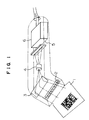
- Fig. 1 shows the structure of the bar-code reader based on this invention.
- the bar-code reader includes a light emitter 2 which projects a light beam onto a bar code symbol printed on a label 1.
- the reflected light from the label 1 is conducted by way of a mirror 3 and lens 4 to a linear image sensor 5, which is connected electrically to a circuit section 6.
- the light emitter 2 consists of an alignment of multiple LEDs having a 660 nm wavelength.
- the linear image sensor 5 is formed of a CCD (charge coupled device) linear image sensor of 3648 pixels, and it functions to convert a bar code image focused by the lens 4 into an electrical signal.
- the circuit section 6 includes a waveform processing circuit, a semiconductor memory as a memory means, and a microprocessor which performs the functions of extraction means and decoding means.
- the image sensor may otherwise be a device based on the CID (charge injection device) or other opto-electric transducing device.
- Sensor elements may be of the point arrangement adopted for a photo-sensor used in a pen-type bar-code reader, or may be of the linear arrangement adopted for a linear image sensor, or may be of the planar arrangement adopted for an area image sensor.
- Bar code symbols which can be read by this bar-code reader include one-dimensional bar code symbols, two-dimensional bar code symbols and multi-stage bar code symbols.
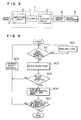
- Fig. 2 shows in block diagram the arrangement of the circuit section 6.
- Indicated by 7 is a waveform processing circuit which amplifies the signal from the linear image sensor 5 and converts the analog signal into a two-level digital signal.
- the circuit 7 consists of an amplifying circuit 10, a filter circuit 11 and a bi-leveling circuit 12 all formed of operational amplifiers or the like.
- Indicated by 8 is a memory means for storing the bar code data derived from the linear image sensor 5 in a serial manner, and it is formed of a semiconductor memory.
- 9 is a microprocessor which functions to extract a bar code symbol from data in the memory 8 and decode the symbol.
- Other electrical components such as LEDs of light emitter and a buzzer which notifies the completion of bar code reading and their associated control circuits are not shown in Fig. 2.
- Fig. 3A shows image data including a two-dimensional bar code symbol stored in the memory 8 through the waveform processing circuit 7.
- a dimension 14 corresponds to the width of reading of the image sensor (number of pixels, i.e., 3648 bits in this embodiment), and a dimension 15 corresponds to the length of reading (3648 bits in this embodiment).
- the capacity of the memory 8 is determined from the required resolution and the cost.
- Fig. 3B shows image data including a one-dimensional bar code symbol stored in the memory 8 through the waveform processing circuit 7
- Fig. 3C shows image data including a multi-stage bar code symbol stored in the memory 8 through the waveform processing circuit 7.
- Fig. 4 shows in flowchart the operation of the extraction means for extracting a two-dimensional bar code symbol based on the Code49 system from the image data shown in Fig. 3A.
- the memory has a start address 16 located at the center of the left bound.
- the memory address is moved toward the right to detect the first black edge (step 903). If the first black edge is not found (step 905), the start address is shifted (step 904), and the memory address is moved toward the right to detect the first black edge (step 903). Until the first black edge is detected, the start address is shifted and the detecting operation continues (steps 903, 905, 904). In case the first black edge is not detected for all start addresses (step 901), indicative of the absence of bar code symbol in the memory, another image data is stored in the memory (step 902).
- step 905 On detecting the first black edge (step 905), tracing takes place around the object along the black edge until the first black edge is detected, with sets of address and data being memorized. From the stored addresses and data, the circumferential length of the black edge and the area of object are evaluated (step 906). If the circumferential length and area are greater than certain values, the object surrounded by the black edge is determined to be a bar code symbol, or otherwise it is negated (step 907). If the object is not a bar code symbol, the sequence returns to step 904, and the start address is shifted to detect another black edge.
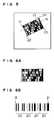
- Fig. 5 shows data of the bar code symbol extracted by the foregoing operation of the extraction means.
- Fig. 6A shows an example of bar code symbol of the Code49 system
- Fig. 6B is a magnified view of one stage of the symbol shown in Fig. 6A.
- Each row of bar code includes a start pattern 18 and a stop pattern 21, indicating the beginning and end of the row.
- a set of stripes 20 forms a symbolic character, and two code character values are calculated from the value of symbolic character.
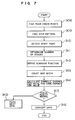
- Fig. 7 shows in flowchart the operation of the decoding means.
- the decoding process for the Code49 system will be explained on this flowchart with reference to Fig. 5 and Figs. 6A and 6B.
- step 908 four corner points of the bar code indicated by 17, 22, 23 and 24 in Fig. 5 are detected (step 908).
- the stop pattern 21 is detected (step 909), and a start point 17 is selected from among the four corner points (step 910).
- White bars are traced by starting from the white bar, which is part of the start pattern 18 located on the inner side of the start point 17, along the addresses and data of the black edge memorized in the step 906 of Fig. 4, and the number of stages is counted based on the black line which exists between adjacent stages as shown in Fig. 6A (step 911).
- a scanning function is defined to be a shortest line which connects the start pattern 18 and stop pattern 21 of each stage (step 912).
- the concept of the scanning function is shown by 19 in Fig. 5.
- the width of bar of each stage is counted in accordance with the scanning function (step 913).
- a code character value is calculated from the symbolic character value 20 which is defined in the Code49 standard, and a checking process for each stage and a checking process for all bar code symbol are implemented (step 914). If the checking processes terminate normally (step 915), the code character value is rendered the data conversion (step 916). If abnormality is detected in the checking processes (step 915), another data is introduced (step 902).
- one-dimensional bar code symbols and multi-stage bar code symbols can also be treated similarly by the extraction means and decoding means of partly different arrangement.
- the bar-code reader When the bar-code reader is set to read bar code symbols of only a certain code system, e.g., Code49, the extraction and decoding time can be reduced, or the bar-code reader can be used efficiently by setting it to read bar code symbols of all kinds, i.e., one-dimensional, two-dimensional and multi-stage bar code symbols.
- a certain code system e.g., Code49
- any of one-dimensional, two-dimensional and multi-stage bar code symbols can be read by scanning the bar code symbol with the bar-code reader and storing data of the whole bar code symbol in the memory.
- this single bar-code reader is operative to read bar code symbols of various kinds, i.e., one-dimensional, two-dimensional and multi-stage bar code symbols, even if the bar-code reader is held in an inclined attitude against the bar code label in which case a complete bar code symbol does not enter at once in the view field of the image sensor, through the operation of memorizing the image sensor output produced from the reflected light from the bar code label in synchronism with the scanning operation, extracting a bar code symbol from the memory, and decoding the bar code symbol.
Abstract
Description
- This invention relates to a bar-code reader use in the EPOS system and the like.
- Conventional prevailing bar-code readers based on the linear image sensor operate only when a complete bar code symbol including a start and stop patterns enters at once in the view field of the linear image sensor.
- In order to increase information carried by a bar code symbol and reduce the size of symbol, new bar code systems Code49 and Codel6K have been developed recently. These bar codes generally called "two-dimensional bar codes" are intended to increase information and reduce the symbol size by disposing rows of stripes in multiple stages instead of extending the alignment of stripes too long.
- However, conventional bar-code readers based on the linear image sensor are not capable of reading these two-dimensional bar code symbols. Moreover, conventional bar-code readers are not capable of reading even usual bar code symbols if they are held in an inclined attitude against the bar code label in which case a complete bar code symbol including a start and stop patterns does not enter at once in the view field of the image sensor.
- This invention is intended to overcome the foregoing prior art deficiencies, and its prime object is to provide a bar-code reader capable of reading two-dimensional bar code symbols.
- Another object of this invention is to provide a bar-code reader capable of reading one-dimensional bar code symbols in addition to two-dimensional bar code symbols.
- Still another object of this invention is to provide a bar-code reader capable of reading multi-stage bar code symbols in addition to one-dimensional and two-dimensional bar code symbols.
- A further object of this invention is to provide a bar-code reader capable of reading bar code symbols even if it is held in an inclined attitude against the bar code label in which case a complete bar code symbol including a start and stop patterns does not enter at once in the view field of the image sensor.
- In order to achieve the above objectives, the bar-code reader based on this invention comprises a light emission means for projecting a light beam onto a bar code label, a light reception means for focusing the reflected light from the label on an image sensor, a signal processing means for processing the output signal of the image sensor, a memory means for storing data provided by the signal processing means in a serial manner in synchronism with the scanning across the bar code label, an extraction means for extracting a bar code symbol from data in the memory means, and a decoding means for decoding the bar code symbol based on the output of the extraction means. The bar-code reader is operative to read one-dimensional bar code symbols, two-dimensional bar code symbols and multi-stage bar code symbols.
- Based on the foregoing arrangement of the bar-code reader, the image sensor output which is derived from the reflected light from the bar code label is memorized during the scanning operation and the bar code symbol is decoded based on the bar code data read out of the memory, and consequently even if the bar-code reader is held in an inclined attitude against the bar code label in which case a complete bar code symbol does not enter at once in the view field of the image sensor, bar code symbols of any type can be read.
-
- Fig. 1 is a perspective diagram showing the internal structure of the bar-code reader based on an embodiment of this invention;
- Fig. 2 is a block diagram of the circuit section of the bar-code reader shown in Fig. 1;
- Fig. 3A is a diagram showing, as a pattern figure, the memorized image data including a two-dimensional bar code symbol;
- Fig. 3B is a diagram showing, as a pattern figure, the memorized image data including a one-dimensional bar code symbol;
- Fig. 3C is a diagram showing, as a pattern figure, the memorized image data including a multi-stage bar code symbol;
- Fig. 4 is a flowchart showing the operation of the extraction means;
- Fig. 5 is a diagram showing, as a pattern figure, the memorized image data following the extraction process;
- Fig. 6A is a diagram showing an example of two-dimensional bar code symbols based on the Code49 system;
- Fig. 6B is a magnified view of part of the bar code symbol shown in Fig. 6A; and
- Fig. 7 is a flowchart showing the operation of the decoding means.
- An embodiment of this invention will be described with reference to the drawings.
- Fig. 1 shows the structure of the bar-code reader based on this invention. In the figure, the bar-code reader includes a light emitter 2 which projects a light beam onto a bar code symbol printed on a label 1. The reflected light from the label 1 is conducted by way of a
mirror 3 and lens 4 to alinear image sensor 5, which is connected electrically to acircuit section 6. - The light emitter 2 consists of an alignment of multiple LEDs having a 660 nm wavelength. The
linear image sensor 5 is formed of a CCD (charge coupled device) linear image sensor of 3648 pixels, and it functions to convert a bar code image focused by the lens 4 into an electrical signal. Thecircuit section 6 includes a waveform processing circuit, a semiconductor memory as a memory means, and a microprocessor which performs the functions of extraction means and decoding means. - The image sensor may otherwise be a device based on the CID (charge injection device) or other opto-electric transducing device. Sensor elements may be of the point arrangement adopted for a photo-sensor used in a pen-type bar-code reader, or may be of the linear arrangement adopted for a linear image sensor, or may be of the planar arrangement adopted for an area image sensor.
- Bar code symbols which can be read by this bar-code reader include one-dimensional bar code symbols, two-dimensional bar code symbols and multi-stage bar code symbols.
- Fig. 2 shows in block diagram the arrangement of the
circuit section 6. Indicated by 7 is a waveform processing circuit which amplifies the signal from thelinear image sensor 5 and converts the analog signal into a two-level digital signal. The circuit 7 consists of anamplifying circuit 10, a filter circuit 11 and abi-leveling circuit 12 all formed of operational amplifiers or the like. - Indicated by 8 is a memory means for storing the bar code data derived from the
linear image sensor 5 in a serial manner, and it is formed of a semiconductor memory. 9 is a microprocessor which functions to extract a bar code symbol from data in the memory 8 and decode the symbol. Other electrical components such as LEDs of light emitter and a buzzer which notifies the completion of bar code reading and their associated control circuits are not shown in Fig. 2. - Fig. 3A shows image data including a two-dimensional bar code symbol stored in the memory 8 through the waveform processing circuit 7. A
dimension 14 corresponds to the width of reading of the image sensor (number of pixels, i.e., 3648 bits in this embodiment), and adimension 15 corresponds to the length of reading (3648 bits in this embodiment). The capacity of the memory 8 is determined from the required resolution and the cost. - Fig. 3B shows image data including a one-dimensional bar code symbol stored in the memory 8 through the waveform processing circuit 7, and Fig. 3C shows image data including a multi-stage bar code symbol stored in the memory 8 through the waveform processing circuit 7.
- Fig. 4 shows in flowchart the operation of the extraction means for extracting a two-dimensional bar code symbol based on the Code49 system from the image data shown in Fig. 3A.
- The memory has a
start address 16 located at the center of the left bound. The memory address is moved toward the right to detect the first black edge (step 903). If the first black edge is not found (step 905), the start address is shifted (step 904), and the memory address is moved toward the right to detect the first black edge (step 903). Until the first black edge is detected, the start address is shifted and the detecting operation continues (steps - On detecting the first black edge (step 905), tracing takes place around the object along the black edge until the first black edge is detected, with sets of address and data being memorized. From the stored addresses and data, the circumferential length of the black edge and the area of object are evaluated (step 906). If the circumferential length and area are greater than certain values, the object surrounded by the black edge is determined to be a bar code symbol, or otherwise it is negated (step 907). If the object is not a bar code symbol, the sequence returns to step 904, and the start address is shifted to detect another black edge.
- Fig. 5 shows data of the bar code symbol extracted by the foregoing operation of the extraction means.
- Fig. 6A shows an example of bar code symbol of the Code49 system, and Fig. 6B is a magnified view of one stage of the symbol shown in Fig. 6A. Each row of bar code includes a
start pattern 18 and astop pattern 21, indicating the beginning and end of the row. A set ofstripes 20 forms a symbolic character, and two code character values are calculated from the value of symbolic character. - Fig. 7 shows in flowchart the operation of the decoding means. The decoding process for the Code49 system will be explained on this flowchart with reference to Fig. 5 and Figs. 6A and 6B.
- Initially, four corner points of the bar code indicated by 17, 22, 23 and 24 in Fig. 5 are detected (step 908). Next, the
stop pattern 21 is detected (step 909), and astart point 17 is selected from among the four corner points (step 910). - White bars are traced by starting from the white bar, which is part of the
start pattern 18 located on the inner side of thestart point 17, along the addresses and data of the black edge memorized in thestep 906 of Fig. 4, and the number of stages is counted based on the black line which exists between adjacent stages as shown in Fig. 6A (step 911). - A scanning function is defined to be a shortest line which connects the
start pattern 18 and stoppattern 21 of each stage (step 912). The concept of the scanning function is shown by 19 in Fig. 5. The width of bar of each stage is counted in accordance with the scanning function (step 913). - Based on the count value, a code character value is calculated from the
symbolic character value 20 which is defined in the Code49 standard, and a checking process for each stage and a checking process for all bar code symbol are implemented (step 914). If the checking processes terminate normally (step 915), the code character value is rendered the data conversion (step 916). If abnormality is detected in the checking processes (step 915), another data is introduced (step 902). - Although the operation for a two-dimensional bar code based on the Code49 system has been explained, one-dimensional bar code symbols and multi-stage bar code symbols can also be treated similarly by the extraction means and decoding means of partly different arrangement.
- When the bar-code reader is set to read bar code symbols of only a certain code system, e.g., Code49, the extraction and decoding time can be reduced, or the bar-code reader can be used efficiently by setting it to read bar code symbols of all kinds, i.e., one-dimensional, two-dimensional and multi-stage bar code symbols.
- Consequently, even if the bar-code reader is held in an inclined attitude against the bar code label in which case a complete bar code symbol does not enter at once in the view field of the image sensor, any of one-dimensional, two-dimensional and multi-stage bar code symbols can be read by scanning the bar code symbol with the bar-code reader and storing data of the whole bar code symbol in the memory.
- According to this invention, as described above for its specific embodiment, this single bar-code reader is operative to read bar code symbols of various kinds, i.e., one-dimensional, two-dimensional and multi-stage bar code symbols, even if the bar-code reader is held in an inclined attitude against the bar code label in which case a complete bar code symbol does not enter at once in the view field of the image sensor, through the operation of memorizing the image sensor output produced from the reflected light from the bar code label in synchronism with the scanning operation, extracting a bar code symbol from the memory, and decoding the bar code symbol.
Claims (8)
- A bar-code reader characterized by comprising: light emission means (2) for projecting a light beam onto a bar code label; light reception means (4) for focusing the reflected light from the bar code label on an image sensor (5); signal processing means (7) for processing the output signal of said image sensor; memory means (8) for storing data provided by said signal processing means in a serial manner in synchronism with the scanning across the bar code symbol; extraction means (9) for extracting a bar code symbol from said memory means; and decoding means (9) for decoding the bar code symbol based on the output of said signal processing means.
- A bar-code reader according to claim 1, characterized in that said image sensor (5) comprises a linear image sensor.
- A bar-code reader according to claim 1, characterized in that said decoding means (9) functions to decode one-dimensional bar code symbols.
- A bar-code reader according to claim 1, characterized in that said decoding means (9) functions to decode two-dimensional bar code symbols.
- A bar-code reader according to claim 1, characterized in that said decoding means (9) functions to decode multi-stage bar code symbols.
- A bar-code reader according to claim 3, characterized in that said decoding means (9) functions to decode multi-stage bar code symbols in addition to one-dimensional bar code symbols.
- A bar-code reader according to claim 3, characterized in that said decoding means (9) functions to decode two-dimensional bar code symbols in addition to one-dimensional bar code symbols.
- A bar-code reader according to claim 1, characterized in that said decoding means (9) functions to decode multi-stage bar code symbols in addition to one-dimensional bar code symbols and two-dimensional bar code symbols.
Applications Claiming Priority (2)
| Application Number | Priority Date | Filing Date | Title |
|---|---|---|---|
| JP4161543A JP2746501B2 (en) | 1992-06-22 | 1992-06-22 | Barcode reader |
| JP161543/92 | 1992-06-22 |
Publications (3)
| Publication Number | Publication Date |
|---|---|
| EP0576220A2 true EP0576220A2 (en) | 1993-12-29 |
| EP0576220A3 EP0576220A3 (en) | 1994-01-19 |
| EP0576220B1 EP0576220B1 (en) | 1998-11-04 |
Family
ID=15737106
Family Applications (1)
| Application Number | Title | Priority Date | Filing Date |
|---|---|---|---|
| EP93304784A Expired - Lifetime EP0576220B1 (en) | 1992-06-22 | 1993-06-18 | Bar-code reader device |
Country Status (4)
| Country | Link |
|---|---|
| US (1) | US5471041A (en) |
| EP (1) | EP0576220B1 (en) |
| JP (1) | JP2746501B2 (en) |
| DE (1) | DE69321881T2 (en) |
Cited By (3)
| Publication number | Priority date | Publication date | Assignee | Title |
|---|---|---|---|---|
| EP0676662A2 (en) * | 1994-04-05 | 1995-10-11 | Noritsu Koki Co., Ltd. | Apparatus and method for reading film information for cartridge |
| EP0690403A3 (en) * | 1994-06-30 | 1996-07-03 | Symbol Technologies, Inc. | Bar code reader for reading both one dimensional and two dimensional symbologies with programmable resolution |
| WO2005004093A2 (en) * | 2003-07-07 | 2005-01-13 | Sirona Inc. | Bar encoding scheme for a scrolling display |
Families Citing this family (10)
| Publication number | Priority date | Publication date | Assignee | Title |
|---|---|---|---|---|
| US7387253B1 (en) | 1996-09-03 | 2008-06-17 | Hand Held Products, Inc. | Optical reader system comprising local host processor and optical reader |
| US5513264A (en) * | 1994-04-05 | 1996-04-30 | Metanetics Corporation | Visually interactive encoding and decoding of dataforms |
| US5631457A (en) * | 1994-08-17 | 1997-05-20 | Olympus Optical Co., Ltd. | Two-dimensional symbol data read apparatus |
| US5739518A (en) * | 1995-05-17 | 1998-04-14 | Metanetics Corporation | Autodiscrimination for dataform decoding and standardized recording |
| US6338432B1 (en) * | 1997-02-19 | 2002-01-15 | Opticon Inc | Optical pattern reading apparatus with movable optical unit |
| US8682077B1 (en) | 2000-11-28 | 2014-03-25 | Hand Held Products, Inc. | Method for omnidirectional processing of 2D images including recognizable characters |
| US6854642B2 (en) * | 2001-10-19 | 2005-02-15 | Chesterfield Holdings, L.L.C. | System for vending products and services using an identification card and associated methods |
| US7416125B2 (en) * | 2005-03-24 | 2008-08-26 | Hand Held Products, Inc. | Synthesis decoding and methods of use thereof |
| JP5026475B2 (en) * | 2009-07-10 | 2012-09-12 | 東芝テック株式会社 | Code symbol reader and its control program |
| EP2393036B1 (en) * | 2010-06-01 | 2016-03-02 | Fujian Newland Computer Co., Ltd. | Barcode decoding chip |
Citations (4)
| Publication number | Priority date | Publication date | Assignee | Title |
|---|---|---|---|---|
| EP0273554A2 (en) * | 1986-12-22 | 1988-07-06 | Symbol Technologies, Inc. | Scan pattern generator for bar code symbol readers |
| EP0385478A2 (en) * | 1989-03-01 | 1990-09-05 | Symbol Technologies, Inc. | Bar code reader |
| EP0384955A2 (en) * | 1989-03-01 | 1990-09-05 | Symbol Technologies, Inc. | Laser scanner for reading two dimensional bar codes |
| WO1993018478A1 (en) * | 1992-03-12 | 1993-09-16 | Norand Corporation | Reader for decoding two-dimensional optical information |
Family Cites Families (8)
| Publication number | Priority date | Publication date | Assignee | Title |
|---|---|---|---|---|
| JPH07107688B2 (en) * | 1986-03-18 | 1995-11-15 | 日本電装株式会社 | Optical information reader |
| US4794239A (en) * | 1987-10-13 | 1988-12-27 | Intermec Corporation | Multitrack bar code and associated decoding method |
| US5235167A (en) * | 1988-10-21 | 1993-08-10 | Symbol Technologies, Inc. | Laser scanning system and scanning method for reading bar codes |
| US5319181A (en) * | 1992-03-16 | 1994-06-07 | Symbol Technologies, Inc. | Method and apparatus for decoding two-dimensional bar code using CCD/CMD camera |
| EP0565738A1 (en) * | 1990-01-05 | 1993-10-20 | Symbol Technologies, Inc. | System for encoding and decoding data in machine readable graphic form |
| US5241164A (en) * | 1990-01-05 | 1993-08-31 | Symbol Technologies, Inc. | Method of decoding bar code symbols from partial scans |
| JPH0464187A (en) * | 1990-07-02 | 1992-02-28 | Sumitomo Electric Ind Ltd | Bar code reader |
| US5124537A (en) * | 1990-10-29 | 1992-06-23 | Omniplanar, Inc. | Omnidirectional bar code reader using virtual scan of video raster scan memory |
-
1992
- 1992-06-22 JP JP4161543A patent/JP2746501B2/en not_active Expired - Fee Related
-
1993
- 1993-06-16 US US08/077,096 patent/US5471041A/en not_active Expired - Fee Related
- 1993-06-18 EP EP93304784A patent/EP0576220B1/en not_active Expired - Lifetime
- 1993-06-18 DE DE69321881T patent/DE69321881T2/en not_active Expired - Fee Related
Patent Citations (4)
| Publication number | Priority date | Publication date | Assignee | Title |
|---|---|---|---|---|
| EP0273554A2 (en) * | 1986-12-22 | 1988-07-06 | Symbol Technologies, Inc. | Scan pattern generator for bar code symbol readers |
| EP0385478A2 (en) * | 1989-03-01 | 1990-09-05 | Symbol Technologies, Inc. | Bar code reader |
| EP0384955A2 (en) * | 1989-03-01 | 1990-09-05 | Symbol Technologies, Inc. | Laser scanner for reading two dimensional bar codes |
| WO1993018478A1 (en) * | 1992-03-12 | 1993-09-16 | Norand Corporation | Reader for decoding two-dimensional optical information |
Cited By (7)
| Publication number | Priority date | Publication date | Assignee | Title |
|---|---|---|---|---|
| EP0676662A2 (en) * | 1994-04-05 | 1995-10-11 | Noritsu Koki Co., Ltd. | Apparatus and method for reading film information for cartridge |
| EP0676662A3 (en) * | 1994-04-05 | 1995-12-13 | Noritsu Koki Co Ltd | Apparatus and method for reading film information for cartridge. |
| US5561284A (en) * | 1994-04-05 | 1996-10-01 | Noritsu Koki Co., Ltd. | Apparatus and method for reading film information for cartridge |
| EP0690403A3 (en) * | 1994-06-30 | 1996-07-03 | Symbol Technologies, Inc. | Bar code reader for reading both one dimensional and two dimensional symbologies with programmable resolution |
| WO2005004093A2 (en) * | 2003-07-07 | 2005-01-13 | Sirona Inc. | Bar encoding scheme for a scrolling display |
| WO2005004093A3 (en) * | 2003-07-07 | 2005-05-19 | Sirona Inc | Bar encoding scheme for a scrolling display |
| US7121466B2 (en) | 2003-07-07 | 2006-10-17 | Sirona Inc. | Bar encoding scheme for a scrolling display |
Also Published As
| Publication number | Publication date |
|---|---|
| DE69321881D1 (en) | 1998-12-10 |
| JP2746501B2 (en) | 1998-05-06 |
| JPH064699A (en) | 1994-01-14 |
| US5471041A (en) | 1995-11-28 |
| EP0576220B1 (en) | 1998-11-04 |
| DE69321881T2 (en) | 1999-04-22 |
| EP0576220A3 (en) | 1994-01-19 |
Similar Documents
| Publication | Publication Date | Title |
|---|---|---|
| US5473148A (en) | Barcode symbol reading system capable of shortening time for reading and decoding | |
| US5304787A (en) | Locating 2-D bar codes | |
| EP1815402B1 (en) | Self-optimizing symbology reader | |
| EP0576220B1 (en) | Bar-code reader device | |
| EP0576219A2 (en) | Bar-code reader apparatus | |
| US5627358A (en) | System and method for reading two-dimensional barcodes | |
| US5245167A (en) | Bar-code reading apparatus | |
| US5811777A (en) | Method and apparatus for utilizing specular light to image low contrast symbols | |
| US5966463A (en) | Dataform readers using interactive storage and analysis of image data | |
| US5357093A (en) | System and method for converting bar code scan line data into machine-readable code | |
| EP2370930B1 (en) | Minimizing misdecodes in electro-optical readers | |
| EP0063243B1 (en) | Ocr and bar code reader with optimized sensor | |
| US20020088860A1 (en) | Data reader and method of use thereof | |
| JP3140184B2 (en) | Barcode symbol reader | |
| JPH0431436B2 (en) | ||
| JPH09274637A (en) | Two-dimensional code reader | |
| JP2734781B2 (en) | Barcode reader | |
| JP3253733B2 (en) | Barcode symbol reader | |
| JPH06266881A (en) | Bar code symbol reader | |
| JP2773438B2 (en) | Barcode reader | |
| US5835984A (en) | Optical scanner employing smart pixel array | |
| JP3018702B2 (en) | Barcode demodulator | |
| JP2506142B2 (en) | Character reader | |
| JPS61169976A (en) | Bar code symbol | |
| JP2750244B2 (en) | Barcode decoder decoding method |
Legal Events
| Date | Code | Title | Description |
|---|---|---|---|
| PUAI | Public reference made under article 153(3) epc to a published international application that has entered the european phase |
Free format text: ORIGINAL CODE: 0009012 |
|
| PUAL | Search report despatched |
Free format text: ORIGINAL CODE: 0009013 |
|
| AK | Designated contracting states |
Kind code of ref document: A2 Designated state(s): DE FR GB IT |
|
| AK | Designated contracting states |
Kind code of ref document: A3 Designated state(s): DE FR GB IT |
|
| 17P | Request for examination filed |
Effective date: 19940602 |
|
| 17Q | First examination report despatched |
Effective date: 19970409 |
|
| GRAG | Despatch of communication of intention to grant |
Free format text: ORIGINAL CODE: EPIDOS AGRA |
|
| GRAG | Despatch of communication of intention to grant |
Free format text: ORIGINAL CODE: EPIDOS AGRA |
|
| GRAH | Despatch of communication of intention to grant a patent |
Free format text: ORIGINAL CODE: EPIDOS IGRA |
|
| GRAH | Despatch of communication of intention to grant a patent |
Free format text: ORIGINAL CODE: EPIDOS IGRA |
|
| GRAA | (expected) grant |
Free format text: ORIGINAL CODE: 0009210 |
|
| AK | Designated contracting states |
Kind code of ref document: B1 Designated state(s): DE FR GB IT |
|
| REF | Corresponds to: |
Ref document number: 69321881 Country of ref document: DE Date of ref document: 19981210 |
|
| ET | Fr: translation filed | ||
| PLBE | No opposition filed within time limit |
Free format text: ORIGINAL CODE: 0009261 |
|
| STAA | Information on the status of an ep patent application or granted ep patent |
Free format text: STATUS: NO OPPOSITION FILED WITHIN TIME LIMIT |
|
| 26N | No opposition filed | ||
| REG | Reference to a national code |
Ref country code: GB Ref legal event code: IF02 |
|
| PGFP | Annual fee paid to national office [announced via postgrant information from national office to epo] |
Ref country code: FR Payment date: 20060608 Year of fee payment: 14 |
|
| PGFP | Annual fee paid to national office [announced via postgrant information from national office to epo] |
Ref country code: GB Payment date: 20060614 Year of fee payment: 14 |
|
| PGFP | Annual fee paid to national office [announced via postgrant information from national office to epo] |
Ref country code: DE Payment date: 20060615 Year of fee payment: 14 |
|
| PGFP | Annual fee paid to national office [announced via postgrant information from national office to epo] |
Ref country code: IT Payment date: 20060630 Year of fee payment: 14 |
|
| GBPC | Gb: european patent ceased through non-payment of renewal fee |
Effective date: 20070618 |
|
| REG | Reference to a national code |
Ref country code: FR Ref legal event code: ST Effective date: 20080229 |
|
| PG25 | Lapsed in a contracting state [announced via postgrant information from national office to epo] |
Ref country code: DE Free format text: LAPSE BECAUSE OF NON-PAYMENT OF DUE FEES Effective date: 20080101 |
|
| PG25 | Lapsed in a contracting state [announced via postgrant information from national office to epo] |
Ref country code: GB Free format text: LAPSE BECAUSE OF NON-PAYMENT OF DUE FEES Effective date: 20070618 |
|
| PG25 | Lapsed in a contracting state [announced via postgrant information from national office to epo] |
Ref country code: FR Free format text: LAPSE BECAUSE OF NON-PAYMENT OF DUE FEES Effective date: 20070702 |
|
| PG25 | Lapsed in a contracting state [announced via postgrant information from national office to epo] |
Ref country code: IT Free format text: LAPSE BECAUSE OF NON-PAYMENT OF DUE FEES Effective date: 20070618 |