EP0577277A1 - Matable coaxial connector assembly having impedance compensation - Google Patents
Matable coaxial connector assembly having impedance compensation Download PDFInfo
- Publication number
- EP0577277A1 EP0577277A1 EP93304475A EP93304475A EP0577277A1 EP 0577277 A1 EP0577277 A1 EP 0577277A1 EP 93304475 A EP93304475 A EP 93304475A EP 93304475 A EP93304475 A EP 93304475A EP 0577277 A1 EP0577277 A1 EP 0577277A1
- Authority
- EP
- European Patent Office
- Prior art keywords
- jack
- plug
- shell
- coaxial connector
- connector assembly
- Prior art date
- Legal status (The legal status is an assumption and is not a legal conclusion. Google has not performed a legal analysis and makes no representation as to the accuracy of the status listed.)
- Granted
Links
Images


Classifications
-
- H—ELECTRICITY
- H01—ELECTRIC ELEMENTS
- H01R—ELECTRICALLY-CONDUCTIVE CONNECTIONS; STRUCTURAL ASSOCIATIONS OF A PLURALITY OF MUTUALLY-INSULATED ELECTRICAL CONNECTING ELEMENTS; COUPLING DEVICES; CURRENT COLLECTORS
- H01R24/00—Two-part coupling devices, or either of their cooperating parts, characterised by their overall structure
- H01R24/38—Two-part coupling devices, or either of their cooperating parts, characterised by their overall structure having concentrically or coaxially arranged contacts
- H01R24/40—Two-part coupling devices, or either of their cooperating parts, characterised by their overall structure having concentrically or coaxially arranged contacts specially adapted for high frequency
- H01R24/42—Two-part coupling devices, or either of their cooperating parts, characterised by their overall structure having concentrically or coaxially arranged contacts specially adapted for high frequency comprising impedance matching means or electrical components, e.g. filters or switches
- H01R24/44—Two-part coupling devices, or either of their cooperating parts, characterised by their overall structure having concentrically or coaxially arranged contacts specially adapted for high frequency comprising impedance matching means or electrical components, e.g. filters or switches comprising impedance matching means
-
- H—ELECTRICITY
- H01—ELECTRIC ELEMENTS
- H01R—ELECTRICALLY-CONDUCTIVE CONNECTIONS; STRUCTURAL ASSOCIATIONS OF A PLURALITY OF MUTUALLY-INSULATED ELECTRICAL CONNECTING ELEMENTS; COUPLING DEVICES; CURRENT COLLECTORS
- H01R2103/00—Two poles
Definitions
- the present invention relates to an electrical coaxial connector assembly of matable coaxial connectors, and more particularly to the field of coaxial connectors providing compensation for impedance.
- the known coaxial cable device has the following disadvantage. Where a plurality of the connectors are used the sum of the spring forces creates a high resultant force which may make board-to-board connections difficult because it would require a high mating force.
- connection system wherein no spring member is required to generate axial bias on the conductors in order to attain impedance compensation, thereby lowering the requisite mating force of a multiposition connector.
- the present invention is a plug and jack connector assembly for coaxial cables, or for circuit boards, or for cable-to-board applications, wherein the reflection signals are substantially self canceling in summation, thereby preventing power loss.
- the coax connector assembly of the present invention is thus adapted for use in multiposition hybrid connectors having a plurality of such coax connectors in addition possibly to other types of contacts and connectors, tolerating axial and radial misalignment through an impedance self compensating interface without requiring bottoming of the conductors of the mating plug and jack connectors nor requiring spring loading of the outer conductors to effectuate such bottoming.
- the plug and jack connectors being matable without biasing spring members are therefore substantially independent of reference to the housings within which the connectors are retained.
- the pin terminal or center conductor is mounted within a dielectric body coaxially within an outer conductive ring and immediately forwardly of the dielectric body is a conductive sleeve of short axial length and precise inner diameter.
- the socket terminal is similarly held within an outer conductive sleeve by way of a dielectric body.
- the outer conductive sleeve has a conductive shroud having resilient fingers extending forwardly from a larger diameter section of the shroud and forwardly of the socket contact section of the terminal, the fingers adapted for coaxial engagement within the outer conductive sleeve while the larger diameter shroud section is received into the forward end of the conductive ring.
- the pin terminal is coaxially positioned within the conductive shroud when mated with the socket terminal.
- a larger diameter section of the pin terminal extends rearwardly from an axial position of the leading end of the conductive sleeve and at least into the dielectric body, creating two regions of changing diameter relationships within the plug connector.
- the leading end of the spring arms of the shroud of the jack connector engage the inner surface of the conductive sleeve within a region extending between the leading end of the sleeve and the dielectric body, and the bases of the spring arms are joined to the continuous circumference of the reduced diameter leading end of the cylindrical section at a location preferably axially coincident with the forward end of the dielectric body containing the socket contact section recesses therebehind.
- regions of impedance mismatch exist, when the connectors are mated, with the first regions of both connectors coextending for varying lengths depending on the spacing between the housings in which the connectors are mounted which determines the extent to which the leading ends of the spring arms extend into the conductive sleeve, thus leaving variable axial lengths of the second regions outside the region of coextension of the first regions.
- regions of mismatched impedances are created having varying lengths from connector to connector, the regions being adapted to create reflection signals at transition positions between adjacent regions, whereby the reflection signals are substantially self canceling in summation, thereby preventing power loss.
- the three regions define the mating interface between the forward ends of the dielectric bodies containing the inner conductors.
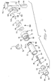
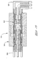
- the connector is shown as 10 comprised of a plug assembly half 40 and a jack assembly half 140 mountable respectively in apertures of housings 12 and 14.
- Plug 40 is shown having a right angle circuit board coaxial connector 100 connectable at a rearward end thereof, while jack 140 is shown adapted to be connected to a terminated coaxial cable at its rearward end.
- plug 40 and jack 140 Upon being secured in housings 12,14 plug 40 and jack 140 would be matable at a mating coaxial interface defined between respective mating faces 42,142 exposed at the mating faces 16,18 of the opposed housings, when the housings are moved axially and matingly together.
- the plug 40 and jack 140 are depicted prior to being inserted into apertures 20,22 within such housings, and prior to transition interfaces 44,144 exposed at rearward faces 24,26 of housings 12,14 being interconnected with a terminated coaxial cable end and a circuit board-mountable coaxial connector 100 respectively (see FIGS. 4 to 7), although the plug and jack may be affixed to cable ends or connectors prior to shipment, for convenience.
- the connectors are shown designed to be mountable and retainable, and removable from, apertures of standard or conventional design and dimension.
- the housings 12 and 14 shown only in part in FIG. 1, may be taken to be wall sections of either panels which can contain a plurality of connectors like 10, or a section through a wall of a connector containing a plurality of connectors 10 and in addition, other connectors for signal, power and ground such as hybrid connectors; the connectors may further be of the type including fiber optic connectors.
- One type of hybrid connector is disclosed in U. S. Patent Application Serial No. 07/855,364 filed March 20, 1992 and assigned to the assignee hereof. Not shown, but understood to be included, would be features mounted on or forming part of the housings including mechanical fasteners adapted to align the housings for mutual closure to effect an interconnect of the connector halves.
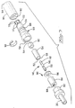
- plug 40 generally has a construction of an inner or central contact 46 mounted within a passageway 48 of dielectric body 50, a front conductive shell 52, and a rear shell 54 receiving a retention snap ring 56 therearound into an annular recess 58, with front and rear shells 52,54 defining an outer conductor.
- Inner contact 46 and dielectric body 50 are retained concentrically within a bore 60 of front shell 52 defining a front shell subassembly, with inner contact 46 including a pin contact forward section 62, a body section 63 and a socket contact rearward section 64.
- Plug 40 further includes an inner conductive sleeve 80 inserted into bore 60 of front shell 52 forwardly of dielectric body 50 in interference fit, for purposes to be discussed later with respect to FIGS. 6 to 9.
- Front shell 52 includes a cylindrical array of spring arms 66 extending from the rearward section, enabling the front shell subassembly to be secured to rear shell 54, spring arms 66 being insertable into the front portion of bore 68 of rear shell 54 and outwardly extending forwardly facing latching surfaces 70 latchable behind rearwardly facing ledge 72 (see FIG. 4) of bore 68, defining plug connector 40.
- Snap ring 56 in its unbiased state has an outer diameter larger than small diameter aperture portion 28 but is deflectable to a smaller outer diameter.
- plug 40 The forward portions of plug 40 are shaped and dimensioned to be insertable into aperture 20 from rearward face 26 until snap ring 56 passes through small diameter aperture portion 28 and resiles forwardly of ledge 30, with outwardly tapered surface 74 engaging the housing aperture walls to initiate radially inward deflection, facilitating insertion.
- Rear shell 54 includes a larger diameter rear portion defining an annular stop 76 which abuts against rearward housing face 26 preventing further axially forward motion.
- Coaxial connector 100 connectable to plug 40 at transition interface 44 thereof.
- Coaxial connector 100 has an outer shell 102, an inner contact 104 with first and second pin contact sections 106,108 extending from a right angle bend 110, a first dielectric body 112 associated with first pin section 106, a second dielectric body 114 associated with second pin section 108, and a spacer 116.
- First pin section 106 extends through passageway 118 of first dielectric body 112 and then inserted into bore 120 of outer shell 102 until flange 122 of body 112 abuts outer shell 102; second pin section follows gap 124 during insertion and passes through gap 126, after which second dielectric body 114 is inserted into outer shell 102 with second pin section 108 entering passageway 128 thereof.
- the pin 46 is beryllium copper
- dielectric body 50 is polytetrafluoroethylene (PTFE)
- front shell 52 is beryllium copper while rear shell 54 may be brass, with the pin contact and front and rear shells being plated with gold over nickel
- retention snap ring 56 may be nickel-plated beryllium copper.
- contact 104 may be brass plated with gold over nickel
- outer shell 102 may be machined of brass and tin-lead plated
- dielectric bodies 112,114 may be PTFE
- spacer 116 may be nickel-plated brass.
- jack connector 140 is seen to include an inner or central contact 146 having a socket contact forward section 148 matable with the pin contact forward section 62 of contact 46 of plug 40, and also having a socket contact rearward section 150.
- Inner contact 146 is mounted within a passageway 152 of rear dielectric body 154 with forward contact section 148 extending forwardly thereof, and rearward contact section 150 exposed within the rearward shroud section 156 thereof.
- Inner contact 146 and rear dielectric body 154 are secured within bore 158 of unitary outer shell 160, along with front dielectric body 162 which is disposed around socket contact forward section 148 and includes a reduced diameter forward section 164 extending to a forward end 165 forwardly of the front end of socket contact section 148.
- front body 162 is spaced radially from the spring arms of socket contact forward section 148 permitting outward deflection thereof by pin contact section 62 upon connector mating (see FIGS. 6 to 9), while small diameter flanged front end 164 thereof defines a relatively rigid chamfered entrance for pin contact section 62 upon mating, thereby aligning the pin with the center of the spring arms of the socket, and also has an outer diameter selected to optimize achievement of 50 ohm impedance rearwardly of forward end 165.
- a retention snap ring 166 is disposed around outer shell 160 of jack 140 within an annular recess 168 to cooperate with reduced diameter rear aperture portion 32 of aperture 22 of housing 14 and latch forwardly of ledge 34 thereof.
- Outer shell 160 includes an array of spring arms 170 extending forwardly of the reduced diameter leading end 172 of cylindrical portion 174 to respective leading ends 176 having outwardly extending arcuate axially rounded embossments to provide conductive engagement between the outer conductors of the plug and jack connectors, and shaped to accommodate bearing engagement and initiate slight radially inward deflection upon initial engagement with the outer conductor of plug 40.
- jack connector 140 also includes a conductive shroud member 180 mounted in aperture 22 having a rear inwardly directed annular flange 182 which latches behind retention snap ring 166 and forwardly of ledge 34, and has a forward section 184 extending forwardly of mating face 18 of connector 14 upon assembly; shroud 180 provides shielding around the mating interface of the inner and outer conductors of the plug and jack connectors when mated, and also serves to precisely align the plug and jack during mating, as is conventional.
- FIGS. 1 and 3 also show an adapter 190 mountable at transition interface 144 of jack 140 and having a rear shell 192, rear dielectric body 194 and spacer 196.
- Adapter 190 provides for crimping of a terminated coaxial cable to jack 140 at the transition interface, as shown in FIG. 5.
- contact 146 and outer shell 160 may be machined of beryllium copper and subsequently plated with gold over nickel.
- Dielectric bodies 154 and 162 may be PTFE, and retention snap ring may be nickel-plated beryllium copper while conductive shroud 180 may be nickel-plated brass.
- Rear shell 192 and spacer 196 may be nickel-plated brass, and rear dielectric body 194 may be PTFE.
- inner conductive sleeve 80 of plug 40 has an outwardly facing surface 82, inwardly facing surface 84, rear edge 86 and inwardly chamfered leading edge 88.
- the outer diameter of inner sleeve 80 is incrementally greater than the inner diameter of the front portion of bore 60 of front shell 52 to define an interference fit when inserted thereinto.
- Dielectric body 50 is preferably machined of somewhat resilient material to have an axial length just greater than the distance between rear flange 90 of front shell 52 and annular ledge 92 along bore 60.
- Inner sleeve 80 is inserted into bore 60 of front shell 52 forwardly of dielectric body 50 until abutting against forwardly facing annular ledge 92, engaging forward end 51 of dielectric body 50 and slightly compressing the resilient material of dielectric body 50 against rear flange 90, thus tending to fill any incremental gaps between dielectric body 50 and front shell 52.
- Inner sleeve 80 thus serves as a retention means for dielectric body 50.
- the length of inner conductive sleeve 80 is selected so that upon assembly, leading edge 88 is axially coincident with shoulder 78 between pin contact section 62 and larger diameter body section 63 of contact member 46, and rearward edge 86 abutting and coincident with forward end 51 of dielectric body 50.
- unitary outer shell 160 of jack 140 includes a transition section 178 between cylindrical portion 174 having a diameter selected to fit within front shell 52 of plug 40, and leading end 172 and spring arms 170 thereof having a reduced diameter complementary to the inner diameter of inner sleeve 80 within which spring arms 170 will be received upon mating.
- Transition section 178 is tapered, and the leading end of front shell 52 is chamfered, all to facilitate receipt of cylindrical portion 174 of unitary outer shell 160 within front shell 52.
- Leading edge 88 of inner sleeve 80 is chamfered to facilitate initial engagement with leading edges 176 of spring arms 170 of unitary outer shell 160 of jack connector 140 upon mating, and radially inward deflection of spring arms 170 assuring spring biased engagement with inner sleeve 80 of plug 40 for assured electrical grounding engagement radially around contact member 46.
- right angle circuit board connector 100 is shown being connected to transition interface 44 of plug 40, with spacer 116 disposed between outer shell 102 and shoulder 75 within the rearward portion of bore 68 of rear shell 54; preferably connector 100 is mounted to transition interface 44 prior to assembling plug 40 into housing 12, such as by force-fit of the cylindrical portion of shell 102 into the rearward end of rear shell 54.
- adapter 190 is being assembled to transition interface 144 of jack 140, with spacer 196 disposed between outer shell 192 and conductive shell 160. Assembly may be accomplished by force-fit of the forward end of adapter shell 192 into the rearward end of outer shell 160 of jack 140.
- Adapter 190 defines a passageway 198 extending inwardly to rear socket contact section 150 of contact 146.
- Coaxial cable end 200 includes an exposed shielding braid section 202 coextending over an insulated inner conductor portion 204 forwardly from which extends inner conductor 206 having a terminal 208 terminated thereto such as by crimping and concluding in a pin contact section 210.
- FIGS. 6 and 7 coaxial cable end 200 is shown connected to jack 140 with adapter 190, with cylindrical flange section 212 of adapter shell 192 having shielding braid 202 crimped thereover using a crimping ferrule 214 to establish a ground connection for the braid; pin contact section 210 of terminal 208 has been matingly received into socket contact section 150 of contact 146 to establish the signal connection between the cable and jack 140.
- FIG. 7 is a longitudinal of the mated connector assembly 10 comprising plug 40 with circuit board connector connected thereto, and jack 140 with cable 200 connected thereto.
- Plug 40 and jack 140 are mated at their complementary mating faces 42,142 to define the mating interface, the region being designated herein as MI for discussion of FIGS. 8 and 9.
- Forward end 184 of shroud 180 is received into aperture 20 of housing 12 and around leading end 61 of front shell 52, and leading ends 176 of spring arms 170 enter bore 60 of front shell 52 around pin contact section 62.
- Pin contact section 62 enters inwardly chamfered forward end 165 of forward section 164 of front dielectric body 162 and is precisely aligned thereby to eventually enter socket contact section 148 spaced rearwardly thereof.
- the final axial fully mated relationship of plug 40 and jack 140 is determined by other features of connector housings 12,14.
- the impedance of any coaxial connector is a function of the inner diameter of the outer conductor, the outer diameter of the inner conductor and the dielectric that separates the two.
- the self compensating section of the present invention has three variable sections of impedance A, B and C defined by four transitions from impedance of one level to the impedance of another level.
- section A is the distance between forward end 51 of dielectric body 50 and the leading edge 176 of spring arms 170 of outer shell 160;
- section B is the distance between leading edge 176 of spring arms 170 and shoulder 78 on pin contact section 62 which is preferably axially coincident with forward edge 88 of sleeve 80; and
- section C is the distance between shoulder 78 and forward end 165 of forward section 164 of front dielectric body 162.
- the impedance through the section of contact member 46 within front shell 52 rearwardly of forward end 51 of dielectric body 50 is nominally 50 ohms, as is the forward or mated portions of pin contact section 62 and socket contact section 148 within continuous cylindrical portion 174 of unitary outer shell 160 rearwardly of the forward end 165 of front dielectric body 162.
- the sections A, B and C do not have nominal impedances of 50 ohms, but rather the impedance of sections A and C is greater than 50 ohms, whereas the impedance of section B is less than 50 ohms.
- the impedance of section A is a function of the diameter of body section 63 of contact member 46 rearwardly of shoulder 78 or twice the radius R3, the inner diameter of conductive inner shell 80 or twice the radius R2, and the dielectric effect of the air between the two.
- the impedance of section B is a function of the diameter (2R3) of body section 63 of contact member 46, the inner diameter (or 2R1) of the spring arms 170 of unitary outer shell 160 forwardly of cylindrical section 174 (after slight radially inward deflection upon engagement with inner sleeve 80), and the dielectric effect of the air between the two.
- the impedance of section C is a function of the diameter of pin contact section 62 (2R4), the inner diameter (2R1) of spring arms 170, and the dielectric effect of the air intermediate the two.
- unitary outer shell 160 and contact member 146 can vary axially between the positions shown in FIGS. 8 and 9 relative to front shell 52 and contact member 46.
- This floatation changes the lengths of the sections A-C, due to the overlapping effect of unitary outer shell 160 of jack 140 with both pin contact section 62 and the larger diameter body portion of contact member 46 of plug 40.
- the change in the length of sections A-C does not change the magnitude of the impedance but, rather, only changes the phase angle through which the impedance operates. Four such reflections occur, one at each of the transition sections T1-T4, as shown in either of FIGS. 8 and 9, due to the instantaneous change in impedance.
- the reflection at T1 is due to the change of impedance between the nominal impedance value of 50 ohms and the impedance value of zone A, likewise the reflection at T4 is due to the change of impedance between the nominal impedance value of 50 ohms and the impedance value of zone C.
- the reflections at T2 and T3 are due to the change of impedance between zones A and B, and B and C, respectively.
- plug half 40 and jack half 140 are shown in their nominal condition in FIG. 7 when the hybrid connector housings 12,14 are fully mated. It should be appreciated that as the jack half 140 is further to the left of nominal, as viewed in FIG. 8, the length of zone B is decreased between the leading ends 176 of spring arms 170 and shoulder 78 of contact member 46. In FIG. 9, jack 140 is further to the right of nominal, and the length of zone B is increased. Such variation in relative axial position of plug 40 and jack 140 occurs as a result of tolerances in the hybrid connector housings 12,14 and in each of the plug connector 40 and jack connector 140.
- the present invention can easily accommodate the additive tolerance limits of 0.030 inches in the connector housings and 0.030 inches in the plug and jack connectors, or a total of 0.060 inches and still perform well within nominal performance requirements at 10 gigaHertz and even up to about 30 gigaHertz.
- the impedance values of zones A-C are 60.289, 42.583 and 57.577 ohms, respectively, and the length in inches of zones A-C, in the positions shown in FIGS. 7-9, are as follows: Zone A Zone B Zone C FIG. 8 0.065'' 0.0205'' 0.0695'' FIG. 7 0.035'' 0.0505'' 0.0395'' FIG. 9 0.005'' 0.0805'' 0.0095'' Furthermore, in the preferred embodiment of the invention, and with reference to FIG.
- the inner diameter of the spring arms 170 of unitary outer shell 160 is 2 R1 or 0.094 inches
- the inner diameter of the inner conductive sleeve 80 is 2 R2 or 0.124 inches
- the outer diameter of contact section 63 rearwardly of shoulder 78 is 2 R3 or 0.045 inches
- the outer diameter of the pin contact section 62 is 2 R4 or 0.036 inches.
- the movement of the spring arm leading ends 176 between the positions of FIGS. 7 to 9, is such that, in each position, the reflections at T1-T4 are substantially self-canceling.
- This is accomplished by designing the mating interface MI of the connector, such that in each of the positions, shown in FIGS. 7 to 9, the sum total of the reflected signals, that is considering both the magnitude and phase angle, are substantially self-canceling.
- the dimensions provided above have provided such a result.
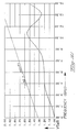
- the graph of FIG. 10 refers to the position shown in FIG. 7: the maximum VSWR is 1.54 which translates to transmitted power of 95.5 % at the input signal with a 4.5 % reflected signal.
- the graph refers to the position shown in FIG. 8: the maximum VSWR is 1.64 which translates to transmitted power of 94.1 % of the input signal with a 5.9 % reflected signal.
- the graph of FIG. 12 refers to the position shown in FIG. 9: the maximum VSWR is 1.77 which translates to transmitted power of 92.2 % of the input signal with a 7.8 % reflected signal.
- This formula represents performance which would be considered acceptable in the industry for a coaxial connector mounted in a multiposition hybrid connector, such as one having a plurality of coaxial connectors mounted in matable housings for simultaneous mating.
- FIGS. 13 to 15 illustrate similar coaxial connector assemblies containing the self compensating mating interface of the present invention.
- FIG. 13 shows an assembly 300 of plug connector 302 and jack connector 304, both adapted for cable-to-cable interconnection using adapter assemblies 306,308 for crimp terminations to the coaxial cables 310,312, similar to the crimp termination of jack 140 to cable 200 of FIGS. 5 to 7 using an adapter assembly 190.
- FIG. 14 shows an assembly 400 of plug connector 402 and jack connector 404, both adapted for cable-to-cable interconnection using inner conductive adapters 406 for solder termination to the outer conductor of semirigid coaxial cables (not shown).
- FIG. 13 shows an assembly 300 of plug connector 302 and jack connector 304, both adapted for cable-to-cable interconnection using adapter assemblies 306,308 for crimp terminations to the coaxial cables 310,312, similar to the crimp termination of jack 140 to cable 200 of FIGS. 5 to 7 using an
- circuit board connector 506 being similar to right angle connector 100 of FIGS. 1 to 7 and circuit board connector 508 being a straight-out connector for vertical mounting to a circuit board, for example.
- the embodiments disclosed herein retain the advantage provided in the mounting of the plug and jack coaxial connectors in the hybrid connector housings which accommodates incremental variations in alignment of centerlines of the respective cavities of the housings in which the coaxial connectors are mounted, by permitting relative incremental angular adjustment of the plug and jack.
- This characteristic is particularly useful in board-to-board arrangements where the connectors are rigidly mounted to the respective boards in approximately corresponding locations suitable for mating when the boards are moved together but which require the ability to incrementally self adjust spacial and angularly to precisely mate in a manner which provides an impedance matched coaxial connection.
- the embodiments require no compression spring means to achieve the selfcompensating impedance characteristics, and thereby result in substantially decreased resistance to mating required to compress the springs to achieve bottoming of the reference planes as in the commercial "Blind Mate" connector design, which amounts to about five pounds per spring, discouraging use of more than two or three such connectors in hybrid connector assemblies and also discouraging disassembly thereof for repair or replacement.
- the present invention has been disclosed in particular embodiments shown and described with respect to FIGS. 1 to 15, but may be useful in other embodiments of coaxial connectors.
Abstract
Description
- The present invention relates to an electrical coaxial connector assembly of matable coaxial connectors, and more particularly to the field of coaxial connectors providing compensation for impedance.
- In U. S. Patent No. 4,697,859 is disclosed fixedly mounting a jack within a rack, whereas the plug is spring loadably mounted to a panel. The connector has the following advantages. The entire plug member including the conductive shroud, the center conductor and the coaxial cable can float to accommodate axial and radial misalignment, thus being especially useful in a rack and panel or "blindmate" situation for remotely located connection. An example of such a connector assembly is sold by AMP Incorporated of Harrisburg, PA under the designation AMP 2.8 Blind Mate coax having Part Nos. 413242-1 and 413249-1, and provides high signal integrity at frequency rating of 40 gigaHertz.
- The known coaxial cable device has the following disadvantage. Where a plurality of the connectors are used the sum of the spring forces creates a high resultant force which may make board-to-board connections difficult because it would require a high mating force.
- It is desired to provide a matable coaxial plug and jack connection system having compensation for impedance.
- It is further desired to provide such a connection system wherein no spring member is required to generate axial bias on the conductors in order to attain impedance compensation, thereby lowering the requisite mating force of a multiposition connector.
- It is additionally desired to provide a coaxial connection system providing high signal integrity in the frequency range of about 10 to 30 gigaHertz and higher.
- It is also desired that such coaxial connection system be especially forgiving of axial and radial misalignment.
- The present invention is a plug and jack connector assembly for coaxial cables, or for circuit boards, or for cable-to-board applications, wherein the reflection signals are substantially self canceling in summation, thereby preventing power loss. The coax connector assembly of the present invention is thus adapted for use in multiposition hybrid connectors having a plurality of such coax connectors in addition possibly to other types of contacts and connectors, tolerating axial and radial misalignment through an impedance self compensating interface without requiring bottoming of the conductors of the mating plug and jack connectors nor requiring spring loading of the outer conductors to effectuate such bottoming. The plug and jack connectors being matable without biasing spring members are therefore substantially independent of reference to the housings within which the connectors are retained.
- In the plug connector the pin terminal or center conductor is mounted within a dielectric body coaxially within an outer conductive ring and immediately forwardly of the dielectric body is a conductive sleeve of short axial length and precise inner diameter. In the jack connector the socket terminal is similarly held within an outer conductive sleeve by way of a dielectric body. The outer conductive sleeve has a conductive shroud having resilient fingers extending forwardly from a larger diameter section of the shroud and forwardly of the socket contact section of the terminal, the fingers adapted for coaxial engagement within the outer conductive sleeve while the larger diameter shroud section is received into the forward end of the conductive ring.
- The pin terminal is coaxially positioned within the conductive shroud when mated with the socket terminal. A larger diameter section of the pin terminal extends rearwardly from an axial position of the leading end of the conductive sleeve and at least into the dielectric body, creating two regions of changing diameter relationships within the plug connector. The leading end of the spring arms of the shroud of the jack connector engage the inner surface of the conductive sleeve within a region extending between the leading end of the sleeve and the dielectric body, and the bases of the spring arms are joined to the continuous circumference of the reduced diameter leading end of the cylindrical section at a location preferably axially coincident with the forward end of the dielectric body containing the socket contact section recesses therebehind.
- Three regions of impedance mismatch exist, when the connectors are mated, with the first regions of both connectors coextending for varying lengths depending on the spacing between the housings in which the connectors are mounted which determines the extent to which the leading ends of the spring arms extend into the conductive sleeve, thus leaving variable axial lengths of the second regions outside the region of coextension of the first regions. Thus regions of mismatched impedances are created having varying lengths from connector to connector, the regions being adapted to create reflection signals at transition positions between adjacent regions, whereby the reflection signals are substantially self canceling in summation, thereby preventing power loss. Together the three regions define the mating interface between the forward ends of the dielectric bodies containing the inner conductors.
- Embodiments of the present invention will now be described by way of example with reference to the accompanying drawings in which
- FIGURE 1 is a perspective view of a matable pair of coaxial connectors of the present invention;
- FIGURES 2 and 3 are exploded perspective views of the matable connectors of FIG. 1;
- FIGURES 4 and 5 are longitudinal section views of the connectors of FIGS. 2 and 3 respectively, with circuit board connectors and cable connectors exploded therefrom at transition interfaces respectively;
- FIGURES 6 and 7 are longitudinal section views of the connectors of FIGS. 4 and 5 positioned to be mated, and fully mated respectively;
- FIGURES 8 and 9 are enlarged longitudinal section views of the mating interface of FIG. 7 with the connectors mated at extreme positions of the axially mated range;
- FIGURES 10 to 12 are graphs of the VSWR versus frequency in gigaHertz for the mated positions of FIGS. 7 to 9 respectively; and
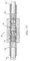
- FIGURES 13 to 15 are longitudinal section views of mated assemblies of other styles of coaxial connections having the mating interface of the present invention, with FIG. 13 adapted for crimped connections with a pair of terminated cables, FIG. 14 adapted for solder connections with a pair of terminated semirigid coaxial cables, and FIG. 15 adapted for board-to-board connection using a right angle board mountable connector and a straight-in board mountable connector.
- Referring first to FIG. 1 and to an embodiment of a coaxial connector assembly employing the features of the invention, the connector is shown as 10 comprised of a
plug assembly half 40 and ajack assembly half 140 mountable respectively in apertures ofhousings Plug 40 is shown having a right angle circuit boardcoaxial connector 100 connectable at a rearward end thereof, whilejack 140 is shown adapted to be connected to a terminated coaxial cable at its rearward end. Upon being secured inhousings plug 40 andjack 140 would be matable at a mating coaxial interface defined between respective mating faces 42,142 exposed at themating faces plug 40 andjack 140 are depicted prior to being inserted intoapertures rearward faces housings coaxial connector 100 respectively (see FIGS. 4 to 7), although the plug and jack may be affixed to cable ends or connectors prior to shipment, for convenience. The connectors are shown designed to be mountable and retainable, and removable from, apertures of standard or conventional design and dimension. - The
housings connectors 10 and in addition, other connectors for signal, power and ground such as hybrid connectors; the connectors may further be of the type including fiber optic connectors. One type of hybrid connector is disclosed in U. S. Patent Application Serial No. 07/855,364 filed March 20, 1992 and assigned to the assignee hereof. Not shown, but understood to be included, would be features mounted on or forming part of the housings including mechanical fasteners adapted to align the housings for mutual closure to effect an interconnect of the connector halves. - Referring to FIGS. 1 and 2,
plug 40 generally has a construction of an inner orcentral contact 46 mounted within apassageway 48 ofdielectric body 50, a frontconductive shell 52, and arear shell 54 receiving aretention snap ring 56 therearound into anannular recess 58, with front andrear shells Inner contact 46 anddielectric body 50 are retained concentrically within abore 60 offront shell 52 defining a front shell subassembly, withinner contact 46 including a pin contactforward section 62, abody section 63 and a socket contactrearward section 64.Plug 40 further includes an innerconductive sleeve 80 inserted intobore 60 offront shell 52 forwardly ofdielectric body 50 in interference fit, for purposes to be discussed later with respect to FIGS. 6 to 9. -
Front shell 52 includes a cylindrical array ofspring arms 66 extending from the rearward section, enabling the front shell subassembly to be secured torear shell 54,spring arms 66 being insertable into the front portion ofbore 68 ofrear shell 54 and outwardly extending forwardly facinglatching surfaces 70 latchable behind rearwardly facing ledge 72 (see FIG. 4) ofbore 68, definingplug connector 40.Snap ring 56 in its unbiased state has an outer diameter larger than smalldiameter aperture portion 28 but is deflectable to a smaller outer diameter. The forward portions ofplug 40 are shaped and dimensioned to be insertable intoaperture 20 fromrearward face 26 untilsnap ring 56 passes through smalldiameter aperture portion 28 and resiles forwardly ofledge 30, with outwardlytapered surface 74 engaging the housing aperture walls to initiate radially inward deflection, facilitating insertion.Rear shell 54 includes a larger diameter rear portion defining anannular stop 76 which abuts againstrearward housing face 26 preventing further axially forward motion. - Also seen in FIGS. 1 and 2 is right angle circuit board
coaxial connector 100 connectable to plug 40 attransition interface 44 thereof.Coaxial connector 100 has anouter shell 102, aninner contact 104 with first and second pin contact sections 106,108 extending from aright angle bend 110, a firstdielectric body 112 associated withfirst pin section 106, a seconddielectric body 114 associated withsecond pin section 108, and aspacer 116.First pin section 106 extends throughpassageway 118 of firstdielectric body 112 and then inserted intobore 120 ofouter shell 102 untilflange 122 ofbody 112 abutsouter shell 102; second pin section followsgap 124 during insertion and passes throughgap 126, after which seconddielectric body 114 is inserted intoouter shell 102 withsecond pin section 108 enteringpassageway 128 thereof. - In the preferred embodiment of the invention, the
pin 46 is beryllium copper,dielectric body 50 is polytetrafluoroethylene (PTFE),front shell 52 is beryllium copper whilerear shell 54 may be brass, with the pin contact and front and rear shells being plated with gold over nickel, andretention snap ring 56 may be nickel-plated beryllium copper. Regardingconnector 100,contact 104 may be brass plated with gold over nickel,outer shell 102 may be machined of brass and tin-lead plated, dielectric bodies 112,114 may be PTFE, andspacer 116 may be nickel-plated brass. - Regarding FIGS. 1 and 3,
jack connector 140 is seen to include an inner orcentral contact 146 having a socket contactforward section 148 matable with the pin contactforward section 62 ofcontact 46 ofplug 40, and also having a socket contact rearwardsection 150.Inner contact 146 is mounted within apassageway 152 of reardielectric body 154 withforward contact section 148 extending forwardly thereof, andrearward contact section 150 exposed within therearward shroud section 156 thereof.Inner contact 146 and reardielectric body 154 are secured withinbore 158 of unitaryouter shell 160, along with frontdielectric body 162 which is disposed around socket contactforward section 148 and includes a reduced diameterforward section 164 extending to aforward end 165 forwardly of the front end ofsocket contact section 148. The inner surface offront body 162 is spaced radially from the spring arms of socket contactforward section 148 permitting outward deflection thereof bypin contact section 62 upon connector mating (see FIGS. 6 to 9), while small diameter flangedfront end 164 thereof defines a relatively rigid chamfered entrance forpin contact section 62 upon mating, thereby aligning the pin with the center of the spring arms of the socket, and also has an outer diameter selected to optimize achievement of 50 ohm impedance rearwardly offorward end 165. - As in
plug connector 40, aretention snap ring 166 is disposed aroundouter shell 160 ofjack 140 within anannular recess 168 to cooperate with reduced diameterrear aperture portion 32 ofaperture 22 ofhousing 14 and latch forwardly ofledge 34 thereof.Outer shell 160 includes an array ofspring arms 170 extending forwardly of the reduceddiameter leading end 172 ofcylindrical portion 174 to respective leadingends 176 having outwardly extending arcuate axially rounded embossments to provide conductive engagement between the outer conductors of the plug and jack connectors, and shaped to accommodate bearing engagement and initiate slight radially inward deflection upon initial engagement with the outer conductor ofplug 40. - Additionally
jack connector 140 also includes aconductive shroud member 180 mounted inaperture 22 having a rear inwardly directedannular flange 182 which latches behindretention snap ring 166 and forwardly ofledge 34, and has aforward section 184 extending forwardly ofmating face 18 ofconnector 14 upon assembly;shroud 180 provides shielding around the mating interface of the inner and outer conductors of the plug and jack connectors when mated, and also serves to precisely align the plug and jack during mating, as is conventional. - FIGS. 1 and 3 also show an
adapter 190 mountable attransition interface 144 ofjack 140 and having arear shell 192, reardielectric body 194 andspacer 196.Adapter 190 provides for crimping of a terminated coaxial cable tojack 140 at the transition interface, as shown in FIG. 5. - In the preferred embodiment of the invention, contact 146 and
outer shell 160 may be machined of beryllium copper and subsequently plated with gold over nickel.Dielectric bodies conductive shroud 180 may be nickel-plated brass.Rear shell 192 andspacer 196 may be nickel-plated brass, and reardielectric body 194 may be PTFE. - In accordance with the present invention, and referring to FIGS. 4 and 2, inner
conductive sleeve 80 ofplug 40 has an outwardly facingsurface 82, inwardly facingsurface 84,rear edge 86 and inwardly chamfered leadingedge 88. The outer diameter ofinner sleeve 80 is incrementally greater than the inner diameter of the front portion ofbore 60 offront shell 52 to define an interference fit when inserted thereinto.Dielectric body 50 is preferably machined of somewhat resilient material to have an axial length just greater than the distance betweenrear flange 90 offront shell 52 andannular ledge 92 alongbore 60.Inner sleeve 80 is inserted intobore 60 offront shell 52 forwardly ofdielectric body 50 until abutting against forwardly facingannular ledge 92, engaging forward end 51 ofdielectric body 50 and slightly compressing the resilient material ofdielectric body 50 againstrear flange 90, thus tending to fill any incremental gaps betweendielectric body 50 andfront shell 52.Inner sleeve 80 thus serves as a retention means fordielectric body 50. The length of innerconductive sleeve 80 is selected so that upon assembly, leadingedge 88 is axially coincident withshoulder 78 betweenpin contact section 62 and largerdiameter body section 63 ofcontact member 46, and rearward edge 86 abutting and coincident withforward end 51 ofdielectric body 50. - In FIG. 5, unitary
outer shell 160 ofjack 140 includes atransition section 178 betweencylindrical portion 174 having a diameter selected to fit withinfront shell 52 ofplug 40, andleading end 172 andspring arms 170 thereof having a reduced diameter complementary to the inner diameter ofinner sleeve 80 within which springarms 170 will be received upon mating.Transition section 178 is tapered, and the leading end offront shell 52 is chamfered, all to facilitate receipt ofcylindrical portion 174 of unitaryouter shell 160 withinfront shell 52. Leadingedge 88 ofinner sleeve 80 is chamfered to facilitate initial engagement with leadingedges 176 ofspring arms 170 of unitaryouter shell 160 ofjack connector 140 upon mating, and radially inward deflection ofspring arms 170 assuring spring biased engagement withinner sleeve 80 ofplug 40 for assured electrical grounding engagement radially aroundcontact member 46. - With respect to FIGS. 4 and 5, right angle
circuit board connector 100 is shown being connected to transitioninterface 44 ofplug 40, withspacer 116 disposed betweenouter shell 102 and shoulder 75 within the rearward portion ofbore 68 ofrear shell 54; preferablyconnector 100 is mounted to transitioninterface 44 prior to assemblingplug 40 intohousing 12, such as by force-fit of the cylindrical portion ofshell 102 into the rearward end ofrear shell 54. In FIG. 5,adapter 190 is being assembled to transitioninterface 144 ofjack 140, withspacer 196 disposed betweenouter shell 192 andconductive shell 160. Assembly may be accomplished by force-fit of the forward end ofadapter shell 192 into the rearward end ofouter shell 160 ofjack 140.Adapter 190 defines apassageway 198 extending inwardly to rearsocket contact section 150 ofcontact 146.Coaxial cable end 200 includes an exposed shieldingbraid section 202 coextending over an insulatedinner conductor portion 204 forwardly from which extendsinner conductor 206 having a terminal 208 terminated thereto such as by crimping and concluding in apin contact section 210. - In FIGS. 6 and 7
coaxial cable end 200 is shown connected to jack 140 withadapter 190, withcylindrical flange section 212 ofadapter shell 192 having shielding braid 202 crimped thereover using a crimpingferrule 214 to establish a ground connection for the braid;pin contact section 210 ofterminal 208 has been matingly received intosocket contact section 150 ofcontact 146 to establish the signal connection between the cable andjack 140. - FIG. 7 is a longitudinal of the mated
connector assembly 10 comprisingplug 40 with circuit board connector connected thereto, andjack 140 withcable 200 connected thereto.Plug 40 andjack 140 are mated at their complementary mating faces 42,142 to define the mating interface, the region being designated herein as MI for discussion of FIGS. 8 and 9. Forward end 184 ofshroud 180 is received intoaperture 20 ofhousing 12 and around leadingend 61 offront shell 52, and leadingends 176 ofspring arms 170 enter bore 60 offront shell 52 aroundpin contact section 62. Inwardly chamfered leadingend 61 offront shell 52 engages outwardly taperedtransition section 178 of unitaryouter shell 160, becoming precisely aligned and positioned with respect thereto, after which leading ends 176 of spring arms engage inwardly chamfered leadingend 88 of innerconductive shell 80 and are deflected slightly radially inwardly.Pin contact section 62 enters inwardly chamfered forward end 165 offorward section 164 of frontdielectric body 162 and is precisely aligned thereby to eventually entersocket contact section 148 spaced rearwardly thereof. The final axial fully mated relationship ofplug 40 andjack 140 is determined by other features ofconnector housings - The impedance of any coaxial connector is a function of the inner diameter of the outer conductor, the outer diameter of the inner conductor and the dielectric that separates the two. As shown in FIGS. 8 and 9, the self compensating section of the present invention has three variable sections of impedance A, B and C defined by four transitions from impedance of one level to the impedance of another level. The section A is the distance between
forward end 51 ofdielectric body 50 and theleading edge 176 ofspring arms 170 ofouter shell 160; section B is the distance between leadingedge 176 ofspring arms 170 andshoulder 78 onpin contact section 62 which is preferably axially coincident withforward edge 88 ofsleeve 80; and section C is the distance betweenshoulder 78 and forward end 165 offorward section 164 of frontdielectric body 162. Thus it should be appreciated that the sections A-C vary in length with the axial displacement of thepin contact section 62 relative to thesocket contact section 148. The impedance through the section ofcontact member 46 withinfront shell 52 rearwardly offorward end 51 ofdielectric body 50 is nominally 50 ohms, as is the forward or mated portions ofpin contact section 62 andsocket contact section 148 within continuouscylindrical portion 174 of unitaryouter shell 160 rearwardly of theforward end 165 of frontdielectric body 162. - However, the sections A, B and C do not have nominal impedances of 50 ohms, but rather the impedance of sections A and C is greater than 50 ohms, whereas the impedance of section B is less than 50 ohms. The impedance of section A is a function of the diameter of
body section 63 ofcontact member 46 rearwardly ofshoulder 78 or twice the radius R₃, the inner diameter of conductiveinner shell 80 or twice the radius R₂, and the dielectric effect of the air between the two. The impedance of section B is a function of the diameter (2R₃) ofbody section 63 ofcontact member 46, the inner diameter (or 2R₁) of thespring arms 170 of unitaryouter shell 160 forwardly of cylindrical section 174 (after slight radially inward deflection upon engagement with inner sleeve 80), and the dielectric effect of the air between the two. Finally, the impedance of section C is a function of the diameter of pin contact section 62 (2R₄), the inner diameter (2R₁) ofspring arms 170, and the dielectric effect of the air intermediate the two. - It should be appreciated then that unitary
outer shell 160 andcontact member 146 can vary axially between the positions shown in FIGS. 8 and 9 relative tofront shell 52 andcontact member 46. This floatation changes the lengths of the sections A-C, due to the overlapping effect of unitaryouter shell 160 ofjack 140 with bothpin contact section 62 and the larger diameter body portion ofcontact member 46 ofplug 40. The change in the length of sections A-C does not change the magnitude of the impedance but, rather, only changes the phase angle through which the impedance operates. Four such reflections occur, one at each of the transition sections T₁-T₄, as shown in either of FIGS. 8 and 9, due to the instantaneous change in impedance. The reflection at T₁ is due to the change of impedance between the nominal impedance value of 50 ohms and the impedance value of zone A, likewise the reflection at T₄ is due to the change of impedance between the nominal impedance value of 50 ohms and the impedance value of zone C. The reflections at T₂ and T₃ are due to the change of impedance between zones A and B, and B and C, respectively. - With reference now to FIGS. 7 to 9, plug
half 40 andjack half 140 are shown in their nominal condition in FIG. 7 when thehybrid connector housings jack half 140 is further to the left of nominal, as viewed in FIG. 8, the length of zone B is decreased between the leading ends 176 ofspring arms 170 andshoulder 78 ofcontact member 46. In FIG. 9,jack 140 is further to the right of nominal, and the length of zone B is increased. Such variation in relative axial position ofplug 40 andjack 140 occurs as a result of tolerances in thehybrid connector housings plug connector 40 andjack connector 140. The present invention can easily accommodate the additive tolerance limits of 0.030 inches in the connector housings and 0.030 inches in the plug and jack connectors, or a total of 0.060 inches and still perform well within nominal performance requirements at 10 gigaHertz and even up to about 30 gigaHertz. - In the preferred embodiment of the invention, the impedance values of zones A-C are 60.289, 42.583 and 57.577 ohms, respectively, and the length in inches of zones A-C, in the positions shown in FIGS. 7-9, are as follows:
Zone A Zone B Zone C FIG. 8 0.065'' 0.0205'' 0.0695'' FIG. 7 0.035'' 0.0505'' 0.0395'' FIG. 9 0.005'' 0.0805'' 0.0095''
Furthermore, in the preferred embodiment of the invention, and with reference to FIG. 8, the inner diameter of thespring arms 170 of unitaryouter shell 160 is 2 R₁ or 0.094 inches, the inner diameter of the innerconductive sleeve 80 is 2 R₂ or 0.124 inches, the outer diameter ofcontact section 63 rearwardly ofshoulder 78 is 2 R₃ or 0.045 inches, the outer diameter of thepin contact section 62 is 2 R₄ or 0.036 inches. - As mentioned above, the movement of the spring arm leading ends 176 between the positions of FIGS. 7 to 9, is such that, in each position, the reflections at T₁-T₄ are substantially self-canceling. This is accomplished by designing the mating interface MI of the connector, such that in each of the positions, shown in FIGS. 7 to 9, the sum total of the reflected signals, that is considering both the magnitude and phase angle, are substantially self-canceling. The dimensions provided above have provided such a result.
- The graph of FIG. 10 refers to the position shown in FIG. 7: the maximum VSWR is 1.54 which translates to transmitted power of 95.5% at the input signal with a 4.5% reflected signal. In FIG. 11, the graph refers to the position shown in FIG. 8: the maximum VSWR is 1.64 which translates to transmitted power of 94.1% of the input signal with a 5.9% reflected signal. And the graph of FIG. 12 refers to the position shown in FIG. 9: the maximum VSWR is 1.77 which translates to transmitted power of 92.2% of the input signal with a 7.8% reflected signal.
- The straight line graph in FIGS. 10 to 12 is a graphic representation of the formula

where
This formula represents performance which would be considered acceptable in the industry for a coaxial connector mounted in a multiposition hybrid connector, such as one having a plurality of coaxial connectors mounted in matable housings for simultaneous mating. - FIGS. 13 to 15 illustrate similar coaxial connector assemblies containing the self compensating mating interface of the present invention. FIG. 13 shows an
assembly 300 ofplug connector 302 andjack connector 304, both adapted for cable-to-cable interconnection using adapter assemblies 306,308 for crimp terminations to the coaxial cables 310,312, similar to the crimp termination ofjack 140 tocable 200 of FIGS. 5 to 7 using anadapter assembly 190. FIG. 14 shows anassembly 400 ofplug connector 402 andjack connector 404, both adapted for cable-to-cable interconnection using innerconductive adapters 406 for solder termination to the outer conductor of semirigid coaxial cables (not shown). FIG. 15 shows anassembly 500 ofplug connector 502 andjack connector 504, having circuit board connectors 506,508 respectively connected at transition interfaces 510,512 respectively, withcircuit board connector 506 being similar toright angle connector 100 of FIGS. 1 to 7 andcircuit board connector 508 being a straight-out connector for vertical mounting to a circuit board, for example. - In addition to providing self compensating impedance accommodating axial variations in mated positions of hybrid connectors, the embodiments disclosed herein retain the advantage provided in the mounting of the plug and jack coaxial connectors in the hybrid connector housings which accommodates incremental variations in alignment of centerlines of the respective cavities of the housings in which the coaxial connectors are mounted, by permitting relative incremental angular adjustment of the plug and jack. This characteristic is particularly useful in board-to-board arrangements where the connectors are rigidly mounted to the respective boards in approximately corresponding locations suitable for mating when the boards are moved together but which require the ability to incrementally self adjust spacial and angularly to precisely mate in a manner which provides an impedance matched coaxial connection.
- Further, the embodiments require no compression spring means to achieve the selfcompensating impedance characteristics, and thereby result in substantially decreased resistance to mating required to compress the springs to achieve bottoming of the reference planes as in the commercial "Blind Mate" connector design, which amounts to about five pounds per spring, discouraging use of more than two or three such connectors in hybrid connector assemblies and also discouraging disassembly thereof for repair or replacement.
- The present invention has been disclosed in particular embodiments shown and described with respect to FIGS. 1 to 15, but may be useful in other embodiments of coaxial connectors.
Claims (7)
- A coaxial connector assembly (10) having a plug (40) and jack (140) having respective inner and outer conductors (46,52;140,180), and a shell member (160) with resilient arms (170) matable at a mating interface, characterized in that:
the mating interface (MI) includes a plurality of regions (A,B,C) of mismatched impedance having varying axial lengths defined by diameter changes of said inner and outer conductors (46,52;140,180) of the plug (40) and jack (140) mating halves between respective dielectric bodies (50,162) thereof. - The coaxial connector assembly of claim 1, wherein an inner conductive sleeve (80) is disposed in the outer conductor (52) and is engaged by leading ends (176) of spring arms (170), whereby the leading ends (176) of the spring arms (170) engage the inward surface of sleeve (76) for matching impedance within a range of axial locations and thereby accommodating variations in the locations of the plug (40) and jack (140).
- The coaxial connector assembly of claim 1, wherein the plug half (40) further includes a rear conductive shell (54) which engages and cooperates with the conductive shell (52) and a housing (12) to form a mating sub-assembly.
- The coaxial connector assembly of claim 3, wherein the rear conductive shell (54) includes a snap-ring (74) which cams inwardly when the rear shell (54) is joined to the housing (12).
- The coaxial connector assembly of any of claims 1-4, wherein the shell member (160) is disposed within the outer conductor member (180) of the jack (140) and the shell (160) further includes a snap-ring (166) for joining the shell (160) to the outer conductor member (180) and a jack housing (14).
- The coaxial connector assembly of any of claims 1-4, wherein the shell member (160) is disposed within the outer conductor member (180) of the jack (140) and the shell (160) further includes dielectric bodies (154,162) which internally accommodate a double female electrical contact (146).
- The coaxial connector assembly of claim 1, wherein the plug half (40) further includes a rear conductive shell (54) which adjoins and cooperates with the conductive shell (52) and a housing (12) to form a mating sub-assembly, and wherein the front conductive shell (52) includes spring arms (66) which cooperate with the rear conductive shell (54).
Applications Claiming Priority (2)
| Application Number | Priority Date | Filing Date | Title |
|---|---|---|---|
| US906258 | 1992-06-29 | ||
| US07/906,258 US5217391A (en) | 1992-06-29 | 1992-06-29 | Matable coaxial connector assembly having impedance compensation |
Publications (2)
| Publication Number | Publication Date |
|---|---|
| EP0577277A1 true EP0577277A1 (en) | 1994-01-05 |
| EP0577277B1 EP0577277B1 (en) | 1997-08-13 |
Family
ID=25422162
Family Applications (1)
| Application Number | Title | Priority Date | Filing Date |
|---|---|---|---|
| EP93304475A Expired - Lifetime EP0577277B1 (en) | 1992-06-29 | 1993-06-11 | Matable coaxial connector assembly having impedance compensation |
Country Status (4)
| Country | Link |
|---|---|
| US (1) | US5217391A (en) |
| EP (1) | EP0577277B1 (en) |
| JP (1) | JP3012116B2 (en) |
| DE (1) | DE69313041T2 (en) |
Cited By (6)
| Publication number | Priority date | Publication date | Assignee | Title |
|---|---|---|---|---|
| EP0844699A2 (en) * | 1996-11-26 | 1998-05-27 | Siemens Aktiengesellschaft | Coaxial connector element |
| WO1999009618A1 (en) * | 1997-08-18 | 1999-02-25 | The Whitaker Corporation | Coaxial cable connector |
| WO1999036999A1 (en) * | 1998-01-15 | 1999-07-22 | Adc Telecommunications, Inc. | Repairable connector and method |
| US5964607A (en) * | 1997-04-04 | 1999-10-12 | Adc Telecommunications, Inc. | Coaxial switching jack with sliding center conductor |
| EP1047156A1 (en) * | 1999-04-22 | 2000-10-25 | Rosenberger Hochfrequenztechnik GmbH & Co. | Coaxial connector |
| WO2015063152A1 (en) * | 2013-11-01 | 2015-05-07 | Huber+Suhner Ag | Coaxial connector assembly |
Families Citing this family (207)
| Publication number | Priority date | Publication date | Assignee | Title |
|---|---|---|---|---|
| US5409398A (en) * | 1993-06-16 | 1995-04-25 | Molex Incorporated | Lighted electrical connector adapter |
| DE4432596A1 (en) * | 1993-09-16 | 1995-03-23 | Whitaker Corp | Modular electrical contact arrangement |
| JP2916665B2 (en) * | 1994-06-28 | 1999-07-05 | 三菱電線工業株式会社 | connector |
| JP3074441B2 (en) * | 1994-10-25 | 2000-08-07 | 矢崎総業株式会社 | Contact movement prevention structure |
| US6042421A (en) * | 1994-12-12 | 2000-03-28 | Itt Manufacturing Enterprises, Inc. | Coaxial connector |
| US5516303A (en) * | 1995-01-11 | 1996-05-14 | The Whitaker Corporation | Floating panel-mounted coaxial connector for use with stripline circuit boards |
| US5695365A (en) * | 1995-01-13 | 1997-12-09 | Telect, Inc. | Communication coaxial patch cord adapter |
| US5645438A (en) * | 1995-01-20 | 1997-07-08 | Ocean Design, Inc. | Underwater-mateable connector for high pressure application |
| JPH0992409A (en) * | 1995-09-25 | 1997-04-04 | Hosiden Corp | Multi-polar jack |
| US5730623A (en) * | 1995-11-01 | 1998-03-24 | Amphenol Corporation | Matched impedance triax contact with grounded connector |
| US5738535A (en) * | 1996-03-07 | 1998-04-14 | Ocean Design, Inc. | Underwater connector |
| US5788535A (en) * | 1996-09-11 | 1998-08-04 | Augat/Lrc Electronics, Inc. | Adaptor assembly |
| DE69734971T2 (en) * | 1996-10-23 | 2006-06-22 | Thomas & Betts International Inc., Sparks | coaxial cable |
| US6036540A (en) * | 1997-05-29 | 2000-03-14 | The Whitaker Corporation | Coaxial connector with ring contact having cantilevered fingers |
| USD440939S1 (en) | 1997-08-02 | 2001-04-24 | Noah P. Montena | Open compression-type coaxial cable connector |
| US6153830A (en) | 1997-08-02 | 2000-11-28 | John Mezzalingua Associates, Inc. | Connector and method of operation |
| US6024609A (en) * | 1997-11-03 | 2000-02-15 | Andrew Corporation | Outer contact spring |
| US6224407B1 (en) * | 1997-12-17 | 2001-05-01 | The Whitaker Corporation | Coaxial switch connector assembly |
| US6019635A (en) * | 1998-02-25 | 2000-02-01 | Radio Frequency Systems, Inc. | Coaxial cable connector assembly |
| DE69831744T2 (en) * | 1998-10-13 | 2006-06-22 | Interlemo Holding S.A. | Connection system for optical fiber contact connectors |
| US6422900B1 (en) | 1999-09-15 | 2002-07-23 | Hh Tower Group | Coaxial cable coupling device |
| US6383031B1 (en) * | 2000-03-31 | 2002-05-07 | Tektronix, Inc. | Keyed electronic interconnect device for high speed signal and data transmission |
| USD437826S1 (en) | 2000-04-28 | 2001-02-20 | John Mezzalingua Associates, Inc. | Closed compression-type coaxial cable connector |
| USD436076S1 (en) | 2000-04-28 | 2001-01-09 | John Mezzalingua Associates, Inc. | Open compression-type coaxial cable connector |
| MXPA02000336A (en) | 2000-05-10 | 2002-06-21 | Thomas & Betts Int | Coaxial connector having detachable locking sleeve. |
| US6413103B1 (en) | 2000-11-28 | 2002-07-02 | Apple Computer, Inc. | Method and apparatus for grounding microcoaxial cables inside a portable computing device |
| DE10115479A1 (en) * | 2001-03-29 | 2002-10-10 | Harting Kgaa | Coaxial plug member |
| USD468696S1 (en) | 2001-09-28 | 2003-01-14 | John Mezzalingua Associates, Inc. | Co-axial cable connector |
| USD461778S1 (en) | 2001-09-28 | 2002-08-20 | John Mezzalingua Associates, Inc. | Co-axial cable connector |
| USD462058S1 (en) | 2001-09-28 | 2002-08-27 | John Mezzalingua Associates, Inc. | Co-axial cable connector |
| USD461166S1 (en) | 2001-09-28 | 2002-08-06 | John Mezzalingua Associates, Inc. | Co-axial cable connector |
| USD462327S1 (en) | 2001-09-28 | 2002-09-03 | John Mezzalingua Associates, Inc. | Co-axial cable connector |
| USD458904S1 (en) | 2001-10-10 | 2002-06-18 | John Mezzalingua Associates, Inc. | Co-axial cable connector |
| USD475975S1 (en) | 2001-10-17 | 2003-06-17 | John Mezzalingua Associates, Inc. | Co-axial cable connector |
| US6953371B2 (en) * | 2002-04-30 | 2005-10-11 | Corning Gilbert Inc. | Apparatus for electrically coupling a linear conductor to a surface conductor and related method |
| DE10316788B3 (en) | 2003-04-11 | 2004-10-21 | Kathrein-Werke Kg | Connection device for connecting at least two radiator devices of an antenna arrangement arranged offset to one another |
| US7329149B2 (en) | 2004-01-26 | 2008-02-12 | John Mezzalingua Associates, Inc. | Clamping and sealing mechanism with multiple rings for cable connector |
| US6808415B1 (en) | 2004-01-26 | 2004-10-26 | John Mezzalingua Associates, Inc. | Clamping and sealing mechanism with multiple rings for cable connector |
| US7029304B2 (en) * | 2004-02-04 | 2006-04-18 | John Mezzalingua Associates, Inc. | Compression connector with integral coupler |
| US20050181667A1 (en) * | 2004-02-17 | 2005-08-18 | Ta-San Kao | Dual-purpose RCA plug structure |
| US7137833B2 (en) * | 2004-02-27 | 2006-11-21 | Thomas & Betts International, Inc. | Compression quick connect/disconnect rotating lug terminal |
| US7241172B2 (en) * | 2004-04-16 | 2007-07-10 | Thomas & Betts International Inc. | Coaxial cable connector |
| US7063565B2 (en) * | 2004-05-14 | 2006-06-20 | Thomas & Betts International, Inc. | Coaxial cable connector |
| TWM257567U (en) * | 2004-06-04 | 2005-02-21 | Molex Taiwan Ltd | A coaxial connector |
| GB0420666D0 (en) * | 2004-09-17 | 2004-10-20 | Smiths Group Plc | Electrical connectors |
| US20060110977A1 (en) | 2004-11-24 | 2006-05-25 | Roger Matthews | Connector having conductive member and method of use thereof |
| US8157589B2 (en) | 2004-11-24 | 2012-04-17 | John Mezzalingua Associates, Inc. | Connector having a conductively coated member and method of use thereof |
| US7108165B2 (en) * | 2004-12-08 | 2006-09-19 | Apex Mfg. Co., Ltd. | Stapler capable of cutting staple legs one after another |
| US7114990B2 (en) | 2005-01-25 | 2006-10-03 | Corning Gilbert Incorporated | Coaxial cable connector with grounding member |
| US7112078B2 (en) * | 2005-02-28 | 2006-09-26 | Gore Enterprise Holdings, Inc. | Gimbling electronic connector |
| IL174146A0 (en) * | 2005-03-11 | 2006-08-01 | Thomas & Betts Int | Coaxial connector with a cable gripping feature |
| CN101253656B (en) * | 2005-06-27 | 2012-01-11 | 普罗布兰德国际有限公司 | End connector for coaxial cable |
| US7455549B2 (en) * | 2005-08-23 | 2008-11-25 | Thomas & Betts International, Inc. | Coaxial cable connector with friction-fit sleeve |
| US20070093128A1 (en) * | 2005-10-20 | 2007-04-26 | Thomas & Betts International, Inc. | Coaxial cable connector having collar with cable gripping features |
| US7347729B2 (en) * | 2005-10-20 | 2008-03-25 | Thomas & Betts International, Inc. | Prepless coaxial cable connector |
| TWM300910U (en) * | 2006-06-02 | 2006-11-11 | Advanced Connectek Inc | Socket connector |
| CN101516427B (en) | 2006-07-28 | 2012-08-08 | 雷斯梅德有限公司 | Delivery of respiratory therapy |
| NZ596570A (en) | 2006-07-28 | 2014-02-28 | Resmed Ltd | Delivery of respiratory therapy |
| US7645163B2 (en) * | 2006-09-13 | 2010-01-12 | John Mezzalingua Associates, Inc. | Step up pin for coax cable connector |
| US7946885B2 (en) * | 2006-09-13 | 2011-05-24 | John Mezzalingua Associates, Inc. | Step up pin for coax cable connector |
| US7351099B1 (en) * | 2006-09-13 | 2008-04-01 | John Mezzalingua Associates, Inc. | Step up pin for coax cable connector |
| US7195524B1 (en) * | 2006-09-26 | 2007-03-27 | Hantechnic Incorporated | Electrical terminal assembly having a detachable coupling head detachable from a terminal by inserting a tool into the coupling head |
| EP2481434B1 (en) | 2006-12-15 | 2016-04-13 | ResMed Ltd. | Delivery of respiratory therapy |
| US7588460B2 (en) * | 2007-04-17 | 2009-09-15 | Thomas & Betts International, Inc. | Coaxial cable connector with gripping ferrule |
| US7794275B2 (en) * | 2007-05-01 | 2010-09-14 | Thomas & Betts International, Inc. | Coaxial cable connector with inner sleeve ring |
| US7566236B2 (en) | 2007-06-14 | 2009-07-28 | Thomas & Betts International, Inc. | Constant force coaxial cable connector |
| US8400318B2 (en) * | 2007-09-24 | 2013-03-19 | John Mezzalingua Associates, Inc. | Method for determining electrical power signal levels in a transmission system |
| US8773255B2 (en) * | 2007-09-24 | 2014-07-08 | Ppc Broadband, Inc. | Status sensing and reporting interface |
| US7733236B2 (en) * | 2007-09-24 | 2010-06-08 | John Mezzalingua Associates, Inc. | Coaxial cable connector and method of use thereof |
| US8149127B2 (en) * | 2007-09-24 | 2012-04-03 | John Mezzalingua Associates, Inc. | Coaxial cable connector with an internal coupler and method of use thereof |
| US8400319B2 (en) * | 2007-09-24 | 2013-03-19 | John Mezzalingua Associates, Inc. | Coaxial cable connector with an external sensor and method of use thereof |
| US8570178B2 (en) * | 2007-09-24 | 2013-10-29 | Ppc Broadband, Inc. | Coaxial cable connector with internal floating ground circuitry and method of use thereof |
| US7753741B2 (en) * | 2008-04-25 | 2010-07-13 | Times Microwave Systems, Inc. | Electrical interconnection systems and methods of assembling the same |
| GB2461346B (en) * | 2008-07-04 | 2013-02-13 | Smiths Group Plc | Electrical connectors |
| CN201303164Y (en) * | 2008-07-24 | 2009-09-02 | 富士康(昆山)电脑接插件有限公司 | Radio frequency coaxial connector |
| US7794274B2 (en) * | 2008-07-30 | 2010-09-14 | Delphi Technologies, Inc. | RF connector with integrated shield |
| US7530813B1 (en) * | 2008-08-18 | 2009-05-12 | Suyin Electronics (Dongguan) Co., Ltd. | Coaxial connector |
| US8075337B2 (en) | 2008-09-30 | 2011-12-13 | Belden Inc. | Cable connector |
| FR2937189A1 (en) * | 2008-10-13 | 2010-04-16 | Radiall Sa | COAXIAL CONNECTOR ELEMENT WITH FACILITY PRETENSION. |
| US8231406B2 (en) * | 2008-10-29 | 2012-07-31 | Corning Gilbert Inc. | RF terminator with improved electrical circuit |
| US7909637B2 (en) * | 2008-11-17 | 2011-03-22 | John Mezzalingua Associates, Inc. | Coaxial connector with integrated mating force sensor and method of use thereof |
| US8419464B2 (en) * | 2008-11-17 | 2013-04-16 | Ppc Broadband, Inc. | Coaxial connector with integrated molded substrate and method of use thereof |
| US8303334B2 (en) * | 2008-11-17 | 2012-11-06 | John Mezzalingua Associates, Inc. | Embedded coupler device and method of use thereof |
| US7850482B2 (en) * | 2008-11-17 | 2010-12-14 | John Mezzalingua Associates, Inc. | Coaxial connector with integrated mating force sensor and method of use thereof |
| US8414326B2 (en) * | 2008-11-17 | 2013-04-09 | Rochester Institute Of Technology | Internal coaxial cable connector integrated circuit and method of use thereof |
| US8376774B2 (en) * | 2008-11-17 | 2013-02-19 | Rochester Institute Of Technology | Power extracting device and method of use thereof |
| US8025518B2 (en) | 2009-02-24 | 2011-09-27 | Corning Gilbert Inc. | Coaxial connector with dual-grip nut |
| US8029315B2 (en) | 2009-04-01 | 2011-10-04 | John Mezzalingua Associates, Inc. | Coaxial cable connector with improved physical and RF sealing |
| US7824216B2 (en) | 2009-04-02 | 2010-11-02 | John Mezzalingua Associates, Inc. | Coaxial cable continuity connector |
| US7892005B2 (en) | 2009-05-19 | 2011-02-22 | John Mezzalingua Associates, Inc. | Click-tight coaxial cable continuity connector |
| US8287320B2 (en) | 2009-05-22 | 2012-10-16 | John Mezzalingua Associates, Inc. | Coaxial cable connector having electrical continuity member |
| US8573996B2 (en) | 2009-05-22 | 2013-11-05 | Ppc Broadband, Inc. | Coaxial cable connector having electrical continuity member |
| US8444445B2 (en) | 2009-05-22 | 2013-05-21 | Ppc Broadband, Inc. | Coaxial cable connector having electrical continuity member |
| US9017101B2 (en) | 2011-03-30 | 2015-04-28 | Ppc Broadband, Inc. | Continuity maintaining biasing member |
| US9570845B2 (en) | 2009-05-22 | 2017-02-14 | Ppc Broadband, Inc. | Connector having a continuity member operable in a radial direction |
| US8854947B2 (en) * | 2009-06-15 | 2014-10-07 | Ppc Broadband, Inc. | Device and method for monitoring a communications system |
| CN201498690U (en) * | 2009-06-24 | 2010-06-02 | 富士康(昆山)电脑接插件有限公司 | Cable connector component |
| US7896655B1 (en) * | 2009-08-14 | 2011-03-01 | Tyco Electronics Corporation | Multi-port connector system |
| US8221161B2 (en) * | 2009-08-28 | 2012-07-17 | Souriau Usa, Inc. | Break-away adapter |
| JP5479841B2 (en) * | 2009-10-13 | 2014-04-23 | 日本圧着端子製造株式会社 | L-shaped coaxial connector |
| US8272893B2 (en) | 2009-11-16 | 2012-09-25 | Corning Gilbert Inc. | Integrally conductive and shielded coaxial cable connector |
| US8618944B2 (en) * | 2009-12-03 | 2013-12-31 | Ppc Broadband, Inc. | Coaxial cable connector parameter monitoring system |
| US8597050B2 (en) * | 2009-12-21 | 2013-12-03 | Corning Gilbert Inc. | Digital, small signal and RF microwave coaxial subminiature push-on differential pair system |
| CN102859803B (en) * | 2010-03-29 | 2016-12-07 | 康宁电磁股份有限公司 | Numeral small-signal and RF microwave coaxial microminiature push type differential pair system |
| US8177582B2 (en) | 2010-04-02 | 2012-05-15 | John Mezzalingua Associates, Inc. | Impedance management in coaxial cable terminations |
| US7934954B1 (en) | 2010-04-02 | 2011-05-03 | John Mezzalingua Associates, Inc. | Coaxial cable compression connectors |
| US9166306B2 (en) | 2010-04-02 | 2015-10-20 | John Mezzalingua Associates, LLC | Method of terminating a coaxial cable |
| US8468688B2 (en) | 2010-04-02 | 2013-06-25 | John Mezzalingua Associates, LLC | Coaxial cable preparation tools |
| TWI549386B (en) | 2010-04-13 | 2016-09-11 | 康寧吉伯特公司 | Coaxial connector with inhibited ingress and improved grounding |
| US8152551B2 (en) | 2010-07-22 | 2012-04-10 | John Mezzalingua Associates, Inc. | Port seizing cable connector nut and assembly |
| US8079860B1 (en) | 2010-07-22 | 2011-12-20 | John Mezzalingua Associates, Inc. | Cable connector having threaded locking collet and nut |
| US8113879B1 (en) | 2010-07-27 | 2012-02-14 | John Mezzalingua Associates, Inc. | One-piece compression connector body for coaxial cable connector |
| US8888526B2 (en) | 2010-08-10 | 2014-11-18 | Corning Gilbert, Inc. | Coaxial cable connector with radio frequency interference and grounding shield |
| US8556656B2 (en) | 2010-10-01 | 2013-10-15 | Belden, Inc. | Cable connector with sliding ring compression |
| US8167636B1 (en) | 2010-10-15 | 2012-05-01 | John Mezzalingua Associates, Inc. | Connector having a continuity member |
| US8075338B1 (en) | 2010-10-18 | 2011-12-13 | John Mezzalingua Associates, Inc. | Connector having a constant contact post |
| US8167646B1 (en) | 2010-10-18 | 2012-05-01 | John Mezzalingua Associates, Inc. | Connector having electrical continuity about an inner dielectric and method of use thereof |
| US8323053B2 (en) | 2010-10-18 | 2012-12-04 | John Mezzalingua Associates, Inc. | Connector having a constant contact nut |
| US8167635B1 (en) | 2010-10-18 | 2012-05-01 | John Mezzalingua Associates, Inc. | Dielectric sealing member and method of use thereof |
| TWI558022B (en) | 2010-10-27 | 2016-11-11 | 康寧吉伯特公司 | Push-on cable connector with a coupler and retention and release mechanism |
| US8337229B2 (en) | 2010-11-11 | 2012-12-25 | John Mezzalingua Associates, Inc. | Connector having a nut-body continuity element and method of use thereof |
| US8604936B2 (en) | 2010-12-13 | 2013-12-10 | Ppc Broadband, Inc. | Coaxial cable connector, system and method of use thereof |
| US8414322B2 (en) | 2010-12-14 | 2013-04-09 | Ppc Broadband, Inc. | Push-on CATV port terminator |
| US8398421B2 (en) | 2011-02-01 | 2013-03-19 | John Mezzalingua Associates, Inc. | Connector having a dielectric seal and method of use thereof |
| US8157588B1 (en) | 2011-02-08 | 2012-04-17 | Belden Inc. | Cable connector with biasing element |
| US8465322B2 (en) | 2011-03-25 | 2013-06-18 | Ppc Broadband, Inc. | Coaxial cable connector |
| US8342879B2 (en) | 2011-03-25 | 2013-01-01 | John Mezzalingua Associates, Inc. | Coaxial cable connector |
| US8366481B2 (en) | 2011-03-30 | 2013-02-05 | John Mezzalingua Associates, Inc. | Continuity maintaining biasing member |
| US8388377B2 (en) | 2011-04-01 | 2013-03-05 | John Mezzalingua Associates, Inc. | Slide actuated coaxial cable connector |
| US8348697B2 (en) | 2011-04-22 | 2013-01-08 | John Mezzalingua Associates, Inc. | Coaxial cable connector having slotted post member |
| WO2012162431A2 (en) | 2011-05-26 | 2012-11-29 | Belden Inc. | Coaxial cable connector with conductive seal |
| US9711917B2 (en) | 2011-05-26 | 2017-07-18 | Ppc Broadband, Inc. | Band spring continuity member for coaxial cable connector |
| US8758050B2 (en) | 2011-06-10 | 2014-06-24 | Hiscock & Barclay LLP | Connector having a coupling member for locking onto a port and maintaining electrical continuity |
| US8591244B2 (en) | 2011-07-08 | 2013-11-26 | Ppc Broadband, Inc. | Cable connector |
| GB201113338D0 (en) * | 2011-08-03 | 2011-09-14 | Rota Eng Ltd | Connector |
| US9190744B2 (en) | 2011-09-14 | 2015-11-17 | Corning Optical Communications Rf Llc | Coaxial cable connector with radio frequency interference and grounding shield |
| US20130072057A1 (en) | 2011-09-15 | 2013-03-21 | Donald Andrew Burris | Coaxial cable connector with integral radio frequency interference and grounding shield |
| US9147955B2 (en) | 2011-11-02 | 2015-09-29 | Ppc Broadband, Inc. | Continuity providing port |
| US8529294B2 (en) | 2011-12-15 | 2013-09-10 | Tyco Electronics Corporation | Coaxial connector with coupling nut |
| US9136654B2 (en) | 2012-01-05 | 2015-09-15 | Corning Gilbert, Inc. | Quick mount connector for a coaxial cable |
| US9407016B2 (en) | 2012-02-22 | 2016-08-02 | Corning Optical Communications Rf Llc | Coaxial cable connector with integral continuity contacting portion |
| US8579659B2 (en) * | 2012-03-13 | 2013-11-12 | Carlisle Interconnect Technologies, Inc. | SMP electrical connector and connector system |
| US9312609B2 (en) * | 2012-10-11 | 2016-04-12 | John Mezzalingua Associates, LLC | Coaxial cable device and method involving weld and mate connectivity |
| WO2014059365A1 (en) * | 2012-10-11 | 2014-04-17 | John Mezzalingua Associates, LLC | Coaxial cable device and method involving weld connectivity |
| US9633765B2 (en) * | 2012-10-11 | 2017-04-25 | John Mezzalingua Associates, LLC | Coaxial cable device having a helical outer conductor and method for effecting weld connectivity |
| US9287659B2 (en) | 2012-10-16 | 2016-03-15 | Corning Optical Communications Rf Llc | Coaxial cable connector with integral RFI protection |
| US9147963B2 (en) | 2012-11-29 | 2015-09-29 | Corning Gilbert Inc. | Hardline coaxial connector with a locking ferrule |
| US9735521B2 (en) | 2013-01-09 | 2017-08-15 | Amphenol Corporation | Float adapter for electrical connector |
| US9039433B2 (en) * | 2013-01-09 | 2015-05-26 | Amphenol Corporation | Electrical connector assembly with high float bullet adapter |
| US9356374B2 (en) | 2013-01-09 | 2016-05-31 | Amphenol Corporation | Float adapter for electrical connector |
| US9153911B2 (en) | 2013-02-19 | 2015-10-06 | Corning Gilbert Inc. | Coaxial cable continuity connector |
| US8882539B2 (en) | 2013-03-14 | 2014-11-11 | Amphenol Corporation | Shunt for electrical connector |
| US9172154B2 (en) | 2013-03-15 | 2015-10-27 | Corning Gilbert Inc. | Coaxial cable connector with integral RFI protection |
| US9276332B2 (en) * | 2013-03-15 | 2016-03-01 | Fct, Us L.L.C. | High-temperature RF connector |
| WO2014172554A1 (en) | 2013-04-17 | 2014-10-23 | Ppc Broadband, Inc. | Post assembly for coaxial cable connectors |
| US10290958B2 (en) | 2013-04-29 | 2019-05-14 | Corning Optical Communications Rf Llc | Coaxial cable connector with integral RFI protection and biasing ring |
| WO2014189718A1 (en) | 2013-05-20 | 2014-11-27 | Corning Optical Communications Rf Llc | Coaxial cable connector with integral rfi protection |
| US9548557B2 (en) | 2013-06-26 | 2017-01-17 | Corning Optical Communications LLC | Connector assemblies and methods of manufacture |
| US9057864B2 (en) | 2013-08-02 | 2015-06-16 | Teledyne Instruments, Inc. | Harsh environment connector with seal closure assisting device |
| US9048599B2 (en) | 2013-10-28 | 2015-06-02 | Corning Gilbert Inc. | Coaxial cable connector having a gripping member with a notch and disposed inside a shell |
| DE102013111905B9 (en) * | 2013-10-29 | 2015-10-29 | Telegärtner Karl Gärtner GmbH | Connecting device for electrically connecting two printed circuit boards |
| AR099038A1 (en) | 2014-01-08 | 2016-06-22 | General Cable Tech Corp | COVERED AIR CONDUCTOR |
| US9077099B1 (en) | 2014-03-05 | 2015-07-07 | Teledyne Instruments, Inc. | Harsh environment connector with rotating end seal assembly |
| NO2704553T3 (en) | 2014-03-27 | 2018-02-03 | ||
| CN106663500A (en) * | 2014-08-05 | 2017-05-10 | 通用线缆技术公司 | Fluoro copolymer coatings for overhead conductors |
| WO2016073309A1 (en) | 2014-11-03 | 2016-05-12 | Corning Optical Communications Rf Llc | Coaxial cable connector with integral rfi protection |
| US9633761B2 (en) | 2014-11-25 | 2017-04-25 | John Mezzalingua Associates, LLC | Center conductor tip |
| CN105990779A (en) * | 2015-02-12 | 2016-10-05 | 鸿富锦精密工业(武汉)有限公司 | Connector plug and connector |
| US10033122B2 (en) | 2015-02-20 | 2018-07-24 | Corning Optical Communications Rf Llc | Cable or conduit connector with jacket retention feature |
| US9590287B2 (en) | 2015-02-20 | 2017-03-07 | Corning Optical Communications Rf Llc | Surge protected coaxial termination |
| US9831619B2 (en) * | 2015-07-08 | 2017-11-28 | Huber+Suhner Ag | Coaxial connector with the ability to prevent damage of accidentally mated connectors |
| US10211547B2 (en) | 2015-09-03 | 2019-02-19 | Corning Optical Communications Rf Llc | Coaxial cable connector |
| WO2017083689A1 (en) | 2015-11-13 | 2017-05-18 | General Cable Technologies Corporation | Cables coated with fluorocopolymer coatings |
| US9525220B1 (en) | 2015-11-25 | 2016-12-20 | Corning Optical Communications LLC | Coaxial cable connector |
| US20180040993A1 (en) * | 2016-01-13 | 2018-02-08 | Shanghai Radiall Electronics Co., Ltd. | Coaxial connection system for rf signals with high rf performance levels |
| CN108701915B (en) | 2016-02-26 | 2020-10-13 | 罗森伯格高频技术有限及两合公司 | Outer conductor arrangement for coaxial plug connector |
| KR102227622B1 (en) * | 2016-02-26 | 2021-03-15 | 로젠버거 호흐프리쿠벤츠테흐닉 게엠베하 운트 코. 카게 | External conductor device for coaxial plug connector |
| CN106299821A (en) * | 2016-08-23 | 2017-01-04 | 深圳市爱得乐电子有限公司 | A kind of blind-mating connector |
| US9935410B2 (en) | 2016-08-26 | 2018-04-03 | Sterling Innovation Inc. | Electrical connector having male and female connectors |
| CN106998021B (en) * | 2017-05-22 | 2023-01-24 | 江苏正恺电子科技有限公司 | Radio frequency coaxial connector |
| US10797412B2 (en) * | 2017-11-21 | 2020-10-06 | Amphenol Corporation | High frequency electrical connector |
| US10505322B2 (en) | 2018-01-19 | 2019-12-10 | Te Connectivity Corporation | Communication system having coaxial connector assembly |
| US10505323B2 (en) | 2018-01-19 | 2019-12-10 | Te Connectivity Corporation | Communication system having coaxial connector assembly |
| US10558000B2 (en) * | 2018-01-22 | 2020-02-11 | Te Connectivity Corporation | Communication system having coaxial connector module and fiber optic module |
| CN110197985A (en) * | 2018-02-24 | 2019-09-03 | 康普技术有限责任公司 | Anti-mis-insertion coaxial connector assemblies |
| CN108631092A (en) * | 2018-03-09 | 2018-10-09 | 苏州瑞可达连接系统股份有限公司 | A kind of plate is to plate radio frequency (RF) coaxial connector |
| TWM567967U (en) * | 2018-05-31 | 2018-10-01 | 正崴精密工業股份有限公司 | Charging connector for electric vehicle and plug connector and receptacle connector thereof |
| JP7093259B2 (en) * | 2018-07-18 | 2022-06-29 | 日本航空電子工業株式会社 | Clothes connector |
| TWM575620U (en) * | 2018-10-25 | 2019-03-11 | 大陸商安費諾光纖技術(深圳)有限公司 | Power Adapter |
| KR102627870B1 (en) * | 2018-12-10 | 2024-01-22 | 한국단자공업 주식회사 | Connector assembly |
| US10992087B2 (en) | 2018-12-13 | 2021-04-27 | Amphenol Corporation | Contact member for electrical connector |
| US10498061B1 (en) | 2018-12-17 | 2019-12-03 | Te Connectivity Corporation | Coaxial connector assembly |
| US10770807B2 (en) * | 2019-01-10 | 2020-09-08 | Amphenol Corporation | Electrical receptacle for coaxial cable |
| EP3726667A1 (en) | 2019-04-15 | 2020-10-21 | TE Connectivity Germany GmbH | Connector for high-frequency transmissions in the automotive field, impedance improving element, connection assembly, method of improving the impedance in a connector |
| EP3780291A1 (en) * | 2019-08-12 | 2021-02-17 | Spinner GmbH | Low passive intermodulation connector system |
| CN112510434A (en) * | 2019-09-16 | 2021-03-16 | 康普技术有限责任公司 | Coaxial connector with axially floating inner contact |
| US11217909B2 (en) | 2019-09-16 | 2022-01-04 | Teledyne Instruments, Inc. | Connector suitable for harsh environments |
| US11489300B2 (en) | 2020-02-20 | 2022-11-01 | Amphenol Corporation | Coupling mechanism and connector with the same |
| US11509075B2 (en) * | 2019-11-12 | 2022-11-22 | Amphenol Corporation | High frequency electrical connector |
| DE102019130743A1 (en) * | 2019-11-14 | 2021-05-20 | Te Connectivity Germany Gmbh | HF terminal for an HF connector, as well as a method for increasing the quality of the signal integrity of a male HF connector or an HF plug connection |
| US11715919B2 (en) | 2020-02-20 | 2023-08-01 | Amphenol Corporation | Coupling mechanism and connector with the same |
| USD993182S1 (en) | 2020-02-20 | 2023-07-25 | Amphenol Corporation | Electrical connector |
| EP3979436A1 (en) * | 2020-10-01 | 2022-04-06 | Rosenberger Hochfrequenztechnik Gmbh & Co. Kg | Electrical connector, circuit board assembly and method for mounting a circuit board assembly |
| TWI750868B (en) * | 2020-10-23 | 2021-12-21 | 禾昌興業股份有限公司 | Circular connector |
| CN112542748B (en) * | 2020-11-05 | 2022-07-08 | 杭州航天电子技术有限公司 | Direct-insertion and direct-pulling type floating connector |
| TWM615534U (en) * | 2021-04-07 | 2021-08-11 | 帛江科技股份有限公司 | Coaxial connector |
| US11435536B1 (en) | 2021-07-29 | 2022-09-06 | Teledyne Instruments, Inc. | Latched optical feedthrough system for subsea wellhead penetration using spherical seals |
Citations (2)
| Publication number | Priority date | Publication date | Assignee | Title |
|---|---|---|---|---|
| US4697859A (en) * | 1986-08-15 | 1987-10-06 | Amp Incorporated | Floating coaxial connector |
| WO1991019333A1 (en) * | 1990-06-08 | 1991-12-12 | W.L. Gore & Associates, Inc. | Connector |
Family Cites Families (7)
| Publication number | Priority date | Publication date | Assignee | Title |
|---|---|---|---|---|
| US4326769A (en) * | 1980-04-21 | 1982-04-27 | Litton Systems, Inc. | Rotary coaxial assembly |
| US4426127A (en) * | 1981-11-23 | 1984-01-17 | Omni Spectra, Inc. | Coaxial connector assembly |
| US4917630A (en) * | 1987-10-15 | 1990-04-17 | The Phoenix Company Of Chicago, Inc. | Constant impedance high frequency coaxial connector |
| US4789351A (en) * | 1988-04-29 | 1988-12-06 | Amp Incorporated | Blind mating connector with snap ring insertion |
| US5037328A (en) * | 1990-05-31 | 1991-08-06 | Amp Incorporated | Foldable dielectric insert for a coaxial contact |
| US5021010A (en) * | 1990-09-27 | 1991-06-04 | Gte Products Corporation | Soldered connector for a shielded coaxial cable |
| US5062808A (en) * | 1991-04-12 | 1991-11-05 | Amp Incorporated | Adapter for interconnecting socket connectors for triaxial cable |
-
1992
- 1992-06-29 US US07/906,258 patent/US5217391A/en not_active Expired - Lifetime
-
1993
- 1993-06-11 EP EP93304475A patent/EP0577277B1/en not_active Expired - Lifetime
- 1993-06-11 DE DE69313041T patent/DE69313041T2/en not_active Expired - Fee Related
- 1993-06-29 JP JP5159764A patent/JP3012116B2/en not_active Expired - Fee Related
Patent Citations (2)
| Publication number | Priority date | Publication date | Assignee | Title |
|---|---|---|---|---|
| US4697859A (en) * | 1986-08-15 | 1987-10-06 | Amp Incorporated | Floating coaxial connector |
| WO1991019333A1 (en) * | 1990-06-08 | 1991-12-12 | W.L. Gore & Associates, Inc. | Connector |
Non-Patent Citations (4)
| Title |
|---|
| ELECTRONIC ENGINEERING vol. 47, no. 571, September 1975, pages 51 - 53 W.TURLEY 'RF connectors-practical design considerations and applications' * |
| ELECTRONIC ENGINEERING vol. 54, no. 669, September 1982, LONDON, GB pages 157 - 164 D.G.LEE ET T.WELBY 'Coaxial connectors in data transmission' * |
| KENSHI MICHISHITA.: "MILLIMETER-BAND COAXIAL CONNECTORS ACCOMMODATE HIGH-FREQUENCY COMMUNICATION NEEDS.", JEE JOURNAL OF ELECTRONIC ENGINEERING., DEMPA PUBLICATIONS INC. TOKYO., JP, vol. 29., no. 302., 1 February 1992 (1992-02-01), JP, pages 52 - 55., XP000287651, ISSN: 0385-4507 * |
| THE ELECTRONIC ENGINEER vol. 25, no. 11, November 1966, pages 110 - 113 T.N.ANDERSON 'What makes a coax connector perform at microwaves?' * |
Cited By (11)
| Publication number | Priority date | Publication date | Assignee | Title |
|---|---|---|---|---|
| EP0844699A2 (en) * | 1996-11-26 | 1998-05-27 | Siemens Aktiengesellschaft | Coaxial connector element |
| EP0844699A3 (en) * | 1996-11-26 | 1999-07-28 | Siemens Aktiengesellschaft | Coaxial connector element |
| US5964607A (en) * | 1997-04-04 | 1999-10-12 | Adc Telecommunications, Inc. | Coaxial switching jack with sliding center conductor |
| EP0972319B1 (en) * | 1997-04-04 | 2002-05-22 | ADC Telecommunications, Inc | Coaxial jack and plug avoiding mismatch impedance |
| WO1999009618A1 (en) * | 1997-08-18 | 1999-02-25 | The Whitaker Corporation | Coaxial cable connector |
| WO1999036999A1 (en) * | 1998-01-15 | 1999-07-22 | Adc Telecommunications, Inc. | Repairable connector and method |
| US5967852A (en) * | 1998-01-15 | 1999-10-19 | Adc Telecommunications, Inc. | Repairable connector and method |
| US6109963A (en) * | 1998-01-15 | 2000-08-29 | Adc Telecommunications, Inc. | Repairable connector and method |
| EP1246316A1 (en) * | 1998-01-15 | 2002-10-02 | ADC Telecommunications, Inc. | Repairable connector and method |
| EP1047156A1 (en) * | 1999-04-22 | 2000-10-25 | Rosenberger Hochfrequenztechnik GmbH & Co. | Coaxial connector |
| WO2015063152A1 (en) * | 2013-11-01 | 2015-05-07 | Huber+Suhner Ag | Coaxial connector assembly |
Also Published As
| Publication number | Publication date |
|---|---|
| JP3012116B2 (en) | 2000-02-21 |
| EP0577277B1 (en) | 1997-08-13 |
| DE69313041D1 (en) | 1997-09-18 |
| DE69313041T2 (en) | 1997-12-04 |
| US5217391A (en) | 1993-06-08 |
| JPH0676890A (en) | 1994-03-18 |
Similar Documents
| Publication | Publication Date | Title |
|---|---|---|
| EP0577277B1 (en) | Matable coaxial connector assembly having impedance compensation | |
| US5329262A (en) | Fixed RF connector having internal floating members with impedance compensation | |
| US4426127A (en) | Coaxial connector assembly | |
| US5474470A (en) | Compensated interface coaxial connector apparatus | |
| EP2465167B1 (en) | Coaxial interconnect and contact | |
| US4925403A (en) | Coaxial transmission medium connector | |
| US5062808A (en) | Adapter for interconnecting socket connectors for triaxial cable | |
| US5037328A (en) | Foldable dielectric insert for a coaxial contact | |
| EP2490304B1 (en) | Coaxial blind mate interconnect and outer conductor for a blind mate interconnect | |
| US4655534A (en) | Right angle coaxial connector | |
| EP0738029B1 (en) | Lockable electrical connector | |
| EP0915536B1 (en) | Coaxial connector | |
| EP0722202A2 (en) | Floating panel-mounted coaxial connector for use with stripline circuit boards | |
| US4917630A (en) | Constant impedance high frequency coaxial connector | |
| JPH0782892B2 (en) | Drawer connector | |
| US5167520A (en) | Cup fit plug connector | |
| US11799243B2 (en) | Electrical connector assembly with RF impedance element | |
| US5237293A (en) | Self-terminating coaxial cable connector | |
| CN1243346A (en) | Contact group | |
| US5879188A (en) | Coaxial connector | |
| WO1998016971A9 (en) | Subminiature matched impedance rf coaxial connector | |
| US6997754B2 (en) | Electrical connector assembly with low crosstalk | |
| EP0339067B1 (en) | Constant impedance high frequency coaxial connector | |
| EP0006343A1 (en) | Plug and receptacle connectors | |
| US6053755A (en) | Connector having an axial resilient inner and outer conductors |
Legal Events
| Date | Code | Title | Description |
|---|---|---|---|
| PUAI | Public reference made under article 153(3) epc to a published international application that has entered the european phase |
Free format text: ORIGINAL CODE: 0009012 |
|
| AK | Designated contracting states |
Kind code of ref document: A1 Designated state(s): DE FR GB |
|
| 17P | Request for examination filed |
Effective date: 19940701 |
|
| 17Q | First examination report despatched |
Effective date: 19960221 |
|
| GRAG | Despatch of communication of intention to grant |
Free format text: ORIGINAL CODE: EPIDOS AGRA |
|
| GRAH | Despatch of communication of intention to grant a patent |
Free format text: ORIGINAL CODE: EPIDOS IGRA |
|
| GRAH | Despatch of communication of intention to grant a patent |
Free format text: ORIGINAL CODE: EPIDOS IGRA |
|
| GRAA | (expected) grant |
Free format text: ORIGINAL CODE: 0009210 |
|
| AK | Designated contracting states |
Kind code of ref document: B1 Designated state(s): DE FR GB |
|
| ET | Fr: translation filed | ||
| REF | Corresponds to: |
Ref document number: 69313041 Country of ref document: DE Date of ref document: 19970918 |
|
| PLBE | No opposition filed within time limit |
Free format text: ORIGINAL CODE: 0009261 |
|
| STAA | Information on the status of an ep patent application or granted ep patent |
Free format text: STATUS: NO OPPOSITION FILED WITHIN TIME LIMIT |
|
| 26N | No opposition filed | ||
| REG | Reference to a national code |
Ref country code: GB Ref legal event code: IF02 |
|
| PGFP | Annual fee paid to national office [announced via postgrant information from national office to epo] |
Ref country code: GB Payment date: 20020501 Year of fee payment: 10 |
|
| PGFP | Annual fee paid to national office [announced via postgrant information from national office to epo] |
Ref country code: FR Payment date: 20020605 Year of fee payment: 10 |
|
| PGFP | Annual fee paid to national office [announced via postgrant information from national office to epo] |
Ref country code: DE Payment date: 20020628 Year of fee payment: 10 |
|
| PG25 | Lapsed in a contracting state [announced via postgrant information from national office to epo] |
Ref country code: GB Free format text: LAPSE BECAUSE OF NON-PAYMENT OF DUE FEES Effective date: 20030611 |
|
| PG25 | Lapsed in a contracting state [announced via postgrant information from national office to epo] |
Ref country code: DE Free format text: LAPSE BECAUSE OF NON-PAYMENT OF DUE FEES Effective date: 20040101 |
|
| GBPC | Gb: european patent ceased through non-payment of renewal fee |
Effective date: 20030611 |
|
| PG25 | Lapsed in a contracting state [announced via postgrant information from national office to epo] |
Ref country code: FR Free format text: LAPSE BECAUSE OF NON-PAYMENT OF DUE FEES Effective date: 20040227 |
|
| REG | Reference to a national code |
Ref country code: FR Ref legal event code: ST |