EP0577532A1 - Electrical energy distribution installation with domestic network communication structure - Google Patents
Electrical energy distribution installation with domestic network communication structure Download PDFInfo
- Publication number
- EP0577532A1 EP0577532A1 EP93420278A EP93420278A EP0577532A1 EP 0577532 A1 EP0577532 A1 EP 0577532A1 EP 93420278 A EP93420278 A EP 93420278A EP 93420278 A EP93420278 A EP 93420278A EP 0577532 A1 EP0577532 A1 EP 0577532A1
- Authority
- EP
- European Patent Office
- Prior art keywords
- room
- electrical energy
- home automation
- server
- link
- Prior art date
- Legal status (The legal status is an assumption and is not a legal conclusion. Google has not performed a legal analysis and makes no representation as to the accuracy of the status listed.)
- Granted
Links
Images


Classifications
-
- H—ELECTRICITY
- H02—GENERATION; CONVERSION OR DISTRIBUTION OF ELECTRIC POWER
- H02J—CIRCUIT ARRANGEMENTS OR SYSTEMS FOR SUPPLYING OR DISTRIBUTING ELECTRIC POWER; SYSTEMS FOR STORING ELECTRIC ENERGY
- H02J3/00—Circuit arrangements for ac mains or ac distribution networks
- H02J3/12—Circuit arrangements for ac mains or ac distribution networks for adjusting voltage in ac networks by changing a characteristic of the network load
- H02J3/14—Circuit arrangements for ac mains or ac distribution networks for adjusting voltage in ac networks by changing a characteristic of the network load by switching loads on to, or off from, network, e.g. progressively balanced loading
-
- H—ELECTRICITY
- H02—GENERATION; CONVERSION OR DISTRIBUTION OF ELECTRIC POWER
- H02J—CIRCUIT ARRANGEMENTS OR SYSTEMS FOR SUPPLYING OR DISTRIBUTING ELECTRIC POWER; SYSTEMS FOR STORING ELECTRIC ENERGY
- H02J13/00—Circuit arrangements for providing remote indication of network conditions, e.g. an instantaneous record of the open or closed condition of each circuitbreaker in the network; Circuit arrangements for providing remote control of switching means in a power distribution network, e.g. switching in and out of current consumers by using a pulse code signal carried by the network
- H02J13/00006—Circuit arrangements for providing remote indication of network conditions, e.g. an instantaneous record of the open or closed condition of each circuitbreaker in the network; Circuit arrangements for providing remote control of switching means in a power distribution network, e.g. switching in and out of current consumers by using a pulse code signal carried by the network characterised by information or instructions transport means between the monitoring, controlling or managing units and monitored, controlled or operated power network element or electrical equipment
- H02J13/00007—Circuit arrangements for providing remote indication of network conditions, e.g. an instantaneous record of the open or closed condition of each circuitbreaker in the network; Circuit arrangements for providing remote control of switching means in a power distribution network, e.g. switching in and out of current consumers by using a pulse code signal carried by the network characterised by information or instructions transport means between the monitoring, controlling or managing units and monitored, controlled or operated power network element or electrical equipment using the power network as support for the transmission
-
- H—ELECTRICITY
- H02—GENERATION; CONVERSION OR DISTRIBUTION OF ELECTRIC POWER
- H02J—CIRCUIT ARRANGEMENTS OR SYSTEMS FOR SUPPLYING OR DISTRIBUTING ELECTRIC POWER; SYSTEMS FOR STORING ELECTRIC ENERGY
- H02J2310/00—The network for supplying or distributing electric power characterised by its spatial reach or by the load
- H02J2310/50—The network for supplying or distributing electric power characterised by its spatial reach or by the load for selectively controlling the operation of the loads
- H02J2310/56—The network for supplying or distributing electric power characterised by its spatial reach or by the load for selectively controlling the operation of the loads characterised by the condition upon which the selective controlling is based
- H02J2310/58—The condition being electrical
-
- Y—GENERAL TAGGING OF NEW TECHNOLOGICAL DEVELOPMENTS; GENERAL TAGGING OF CROSS-SECTIONAL TECHNOLOGIES SPANNING OVER SEVERAL SECTIONS OF THE IPC; TECHNICAL SUBJECTS COVERED BY FORMER USPC CROSS-REFERENCE ART COLLECTIONS [XRACs] AND DIGESTS
- Y02—TECHNOLOGIES OR APPLICATIONS FOR MITIGATION OR ADAPTATION AGAINST CLIMATE CHANGE
- Y02B—CLIMATE CHANGE MITIGATION TECHNOLOGIES RELATED TO BUILDINGS, e.g. HOUSING, HOUSE APPLIANCES OR RELATED END-USER APPLICATIONS
- Y02B70/00—Technologies for an efficient end-user side electric power management and consumption
- Y02B70/30—Systems integrating technologies related to power network operation and communication or information technologies for improving the carbon footprint of the management of residential or tertiary loads, i.e. smart grids as climate change mitigation technology in the buildings sector, including also the last stages of power distribution and the control, monitoring or operating management systems at local level
- Y02B70/3225—Demand response systems, e.g. load shedding, peak shaving
-
- Y—GENERAL TAGGING OF NEW TECHNOLOGICAL DEVELOPMENTS; GENERAL TAGGING OF CROSS-SECTIONAL TECHNOLOGIES SPANNING OVER SEVERAL SECTIONS OF THE IPC; TECHNICAL SUBJECTS COVERED BY FORMER USPC CROSS-REFERENCE ART COLLECTIONS [XRACs] AND DIGESTS
- Y02—TECHNOLOGIES OR APPLICATIONS FOR MITIGATION OR ADAPTATION AGAINST CLIMATE CHANGE
- Y02B—CLIMATE CHANGE MITIGATION TECHNOLOGIES RELATED TO BUILDINGS, e.g. HOUSING, HOUSE APPLIANCES OR RELATED END-USER APPLICATIONS
- Y02B90/00—Enabling technologies or technologies with a potential or indirect contribution to GHG emissions mitigation
- Y02B90/20—Smart grids as enabling technology in buildings sector
-
- Y—GENERAL TAGGING OF NEW TECHNOLOGICAL DEVELOPMENTS; GENERAL TAGGING OF CROSS-SECTIONAL TECHNOLOGIES SPANNING OVER SEVERAL SECTIONS OF THE IPC; TECHNICAL SUBJECTS COVERED BY FORMER USPC CROSS-REFERENCE ART COLLECTIONS [XRACs] AND DIGESTS
- Y04—INFORMATION OR COMMUNICATION TECHNOLOGIES HAVING AN IMPACT ON OTHER TECHNOLOGY AREAS
- Y04S—SYSTEMS INTEGRATING TECHNOLOGIES RELATED TO POWER NETWORK OPERATION, COMMUNICATION OR INFORMATION TECHNOLOGIES FOR IMPROVING THE ELECTRICAL POWER GENERATION, TRANSMISSION, DISTRIBUTION, MANAGEMENT OR USAGE, i.e. SMART GRIDS
- Y04S20/00—Management or operation of end-user stationary applications or the last stages of power distribution; Controlling, monitoring or operating thereof
- Y04S20/20—End-user application control systems
- Y04S20/222—Demand response systems, e.g. load shedding, peak shaving
-
- Y—GENERAL TAGGING OF NEW TECHNOLOGICAL DEVELOPMENTS; GENERAL TAGGING OF CROSS-SECTIONAL TECHNOLOGIES SPANNING OVER SEVERAL SECTIONS OF THE IPC; TECHNICAL SUBJECTS COVERED BY FORMER USPC CROSS-REFERENCE ART COLLECTIONS [XRACs] AND DIGESTS
- Y04—INFORMATION OR COMMUNICATION TECHNOLOGIES HAVING AN IMPACT ON OTHER TECHNOLOGY AREAS
- Y04S—SYSTEMS INTEGRATING TECHNOLOGIES RELATED TO POWER NETWORK OPERATION, COMMUNICATION OR INFORMATION TECHNOLOGIES FOR IMPROVING THE ELECTRICAL POWER GENERATION, TRANSMISSION, DISTRIBUTION, MANAGEMENT OR USAGE, i.e. SMART GRIDS
- Y04S40/00—Systems for electrical power generation, transmission, distribution or end-user application management characterised by the use of communication or information technologies, or communication or information technology specific aspects supporting them
- Y04S40/12—Systems for electrical power generation, transmission, distribution or end-user application management characterised by the use of communication or information technologies, or communication or information technology specific aspects supporting them characterised by data transport means between the monitoring, controlling or managing units and monitored, controlled or operated electrical equipment
- Y04S40/121—Systems for electrical power generation, transmission, distribution or end-user application management characterised by the use of communication or information technologies, or communication or information technology specific aspects supporting them characterised by data transport means between the monitoring, controlling or managing units and monitored, controlled or operated electrical equipment using the power network as support for the transmission
Definitions
- the present invention relates to an electrical energy distribution installation associated with a home automation communication structure, for example for apartment buildings or for the small tertiary sector (small business).
- the single-phase sector arrives at a connection point where the electrical energy meter and the connection circuit breaker are assigned to this housing.
- the invention aims to remedy these drawbacks. It relates for this purpose to an installation for distributing electrical energy from an electrical energy supply line, for a dwelling comprising several rooms, with in each room one or more electrical receivers, this installation being associated to a home automation internal communication structure and characterized in that it comprises, downstream of the connection circuit breaker, a divisional distribution comprising one or more outlets for each of the rooms in the housing, at least one of these outlets ending in the room that it concerns, to a server responsible for distributing energy on individual outgoing lines to electrical receivers in this room, and endowed with an "intelligent" home automation function capable of ensuring, on the one hand, the dialogue between the servers at by means of a global home automation link with an elaborate protocol, and on the other hand, the role of communication interface between said global link and m means of local communication with simplified protocol, specific to each of the rooms, between the server or servers that this room contains, and control members and receivers placed in said room.
- the global home automation link can be carried out indifferently by PLC, thus benefiting from the electrical power supply wiring, or by a wired bus.
- this global internal link between servers is also connected to a transmission and reception link of information to the outside of said premises via the electrical energy supply line.
- rejector filters are provided at each server to isolate the global home automation link from receivers, sources of interference, and at the level of the divisional distribution or branch circuit breaker in order to '' prevent information internal communication between servers can be broadcast to the outside.
- the servers allow a hierarchy of communication between the global link and the local communication means, which greatly simplifies the local communication means, and therefore reduces the costs of the control members and receivers.
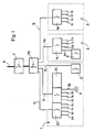
- FIG. 1 is the diagram of the distribution of electrical energy in a room, for example an apartment or villa type dwelling, comprising three rooms 1, 2, 3, each provided with loads such as sockets, lamps lighting 4, a high-power cooking appliance 5, a washing machine 6, etc ...
- connection circuit breaker 7 is conventionally provided at the point of arrival of line 8 of the single-phase electric power supply sector.
- a conventional distributor 39 Immediately downstream of the head circuit breaker 7 is placed a conventional distributor 39, with its divisional circuit breakers, constituting a geographic reflex protection for each room.
- the room 3 comprising several loads, for example a lighting lamp and three sockets, the line 9 ends at a server 14 which, by a home automation control which will be described below with reference to FIG. 2, distributes the electrical energy on different outlets 15 to 18 each connected to a respective load: power outlet or lighting lamp.
- a server 14 which, by a home automation control which will be described below with reference to FIG. 2, distributes the electrical energy on different outlets 15 to 18 each connected to a respective load: power outlet or lighting lamp.
- server 19 is provided, for example identical to server 14, which distributes the incident electric energy on line 10 to several feeders 20 to 23 each suitable for a load, such as load 6 for departure 20.
- the part 1 comprises for example nine charges, including a charge 5 of high power.
- Each particular appliance such as the lamp 4, the cooking appliance 5, or the washing machine 6, is of course normally associated with a local manual start switch, but furthermore all the loads are remotely controllable. , of the room where they are located but also of a adjoining room, thanks to the home automation communications network which is shown diagrammatically in FIG. 2 to which we will now refer.
- the "intelligent" parts of the servers 25, 24, 19, and 14 are interconnected by a global internal link 40 with a protocol developed either by dedicated wire lines, or by line carrying currents, or "PLC " (in such a case, line 40 is also the line for transporting electrical energy).
- PLC line carrying currents
- the geographic reflex protection 39 and the connection circuit breaker 7 are normally transparent for all the information which passes, between servers, in the global internal link 40. If the link 40 is a line carrier link, and in order to confine this information at this link 40, and therefore to prevent them from propagating beyond, forward (to external users via sector 8) or downstream, provision is made, at the connection circuit breaker 7 , and at each of the servers 25, 19, 14, rejector filters, respectively 41 to 45, of the CPL type, easy to supply.
- the cooking appliance 5 which does not depend on any particular server, is connected, from the point of view of intelligent home automation communications, directly to the global internal link bus 40.
- the "intelligent" function of the servers 42 to 45 also provides the communication interface between the global internal link 40 with an elaborate protocol located upstream of the servers, and the local communication means 48 to 59 with a simplified protocol located downstream.
- Such commands are also possible from the outside either by the switched telephone sector, or by radio waves, or others. It is also possible to enter orders, or to make interrogations, via the supply line 8 of electrical energy.
- a specific device such as the washing machine 6, can also be equipped to transmit to the server 19 information on its state on or off, broken or not, using the electric power supply cables as vehicle support, for example with DTMF type signaling superimposed on the 220 volt supply (PLC with simplified protocol).
- PLC DTMF type signaling superimposed on the 220 volt supply
- a server such as the server 25, which is advantageously usable, is a server as described in the French patent application N ° 92.03434 filed March 19, 1992 by the Applicant and summarized below with reference to Figure 3.
- the server 25 is in fact a phase-neutral distribution device of low-voltage single-phase alternative electrical energy to various receivers placed in the room and not shown in the drawing, associated with a dual communication device, a communication developed upstream , and simple downstream communication.
- receivers are electrical devices, television or radio wave receivers, lighting lamps, convectors, household appliances, etc., which can withstand power cuts from a duration which can go up to approximately five milliseconds without visual or actual consequences on their functioning, which would not be the case for certain computing computing devices.
- This server has a common two-wire feed 11, with a phase wire 62 and a neutral wire 63, and here four two-wire feeders 29 to 32 which are branched to this common feed 11, each with its phase wire, such as wire 68 for line 29, and its neutral wire, such as wire 612.
- each outlet 29 to 32 is respectively provided on the one hand a differential earth leakage detector, respectively 616 to 619, and on the other hand an overcurrent detector, respectively 620 to 623, which is placed on the phase wire , all these sensors being independently adjustable for each departure.
- isolation relay On the phase wire of each of these departures 29 to 32 is also placed a remote controlled divisional relay, or isolation relay, respectively 624 to 627, which is constituted by a simple electromechanical relay without breaking capacity, and therefore very inexpensive .
- a small isolation relay of this type responds in about a millisecond.
- An electronic computation and control unit 630 such as a microprocessor, receives the signals from the sensors 16 to 623 and gives opening and closing control orders to the isolation relays 624 to 627, as indicated by the four groups of each three interconnections which are referenced I to IV.
- the aforementioned rejector filter 42 is placed on the arrival line 11, just upstream from the branches 612,68, etc. It is connected to the microprocessor 630 by an optional local communication line 60.
- An electronic static switch 628 is placed, upstream of the filter 42, on the phase wire 62 of the incoming line 11, the control terminal 629 of this static switch being connected to one of the output doors of the microprocessor 630.
- the microprocessor In addition to the automatic "reflex" control which comes from the sensors, the microprocessor also receives and returns information coming from the communication means 48 to 59 and 20 with simplified protocol and those passing on the global link 40.
- the birth of this fault is almost instantaneous transmitted by the sensor, 616 to 623, corresponding to the microprocessor 630.
- the latter reacts immediately by an order to open the static switch 628, followed by an order to open the isolation relay, 624 to 627, concerned (i.e. located on the starting circuit, 29 to 32, which includes this sensor). Then, after the sufficient time for this opening of the isolation relay, it orders the reclosing of the static relay 628.
- the starting line on which the fault occurred is then isolated, while the other three starting lines are restarted.
- one or other of the starting lines 29 to 32 is carried out according to the three aforementioned phases, that is to say that the operation of an isolation relay is always carried out with the switch static 628 open, but however the first phase is simplified by the fact that it is carried out in a single opening time of this static switch, without a second test on the next passage at zero voltage.
Abstract
Description
La présente invention se rapporte à une installation de distribution d'énergie électrique associée à une structure de communication domotique, par exemple pour les immeubles d'habitation ou pour le petit secteur tertiaire (petit commerce).The present invention relates to an electrical energy distribution installation associated with a home automation communication structure, for example for apartment buildings or for the small tertiary sector (small business).
S'agissant par exemple d'une installation de distribution d'énergie électrique vers les différentes pièces d'un logement d'habitation, une telle installation est classiquement prévue de la façon suivante :In the case of, for example, an installation for distributing electrical energy to the various rooms of a residential dwelling, such an installation is conventionally provided as follows:
Le secteur monophasé arrive en un point de branchement où se trouvent le compteur d'énergie électrique et le disjoncteur de branchement qui sont affectés à ce logement.The single-phase sector arrives at a connection point where the electrical energy meter and the connection circuit breaker are assigned to this housing.
En aval du disjoncteur de branchement sont généralement prévus des disjoncteurs divisionnaires qui protègent les différents départs, ces départs étant organisés par fonctions. On y trouve par exemple :
- . quelques départs qui alimentent les prises de courant ;
- . quelques départs qui alimentent les points d'éclairage ;
- . un départ spécifique d'alimentation des salles de bains ;
- . un départ de puissance pour l'alimentation de l'appareil de cuisson ;
- . un départ pour le chauffe-eau électrique ;
- . un départ vers le congélateur.
- . some feeders which supply the sockets;
- . some feeders which feed the lighting points;
- . a specific supply for the bathrooms;
- . a power flow for supplying the cooking appliance;
- . a departure for the electric water heater;
- . a departure to the freezer.
Le réseau résultant de ce câblage classique présente quelques inconvénients dus à des paramètres incontrôlables et variables :
- . sa longueur et son arborescence dans le logement concerné et en dehors ;
- . les charges qu'il alimente sont très varièes et elles sont source de perturbations souvent difficiles à déterminer ;
- . une utilisation du réseau pour le transport local d'information, par exemple par courants porteurs de ligne (C.P.L.), serait problématique car ce circuit ne dispose pas de séparation entre le réseau utile (dans le logement) et le réseau externe qui devrait normalement être interdit.
- . its length and tree structure in the accommodation concerned and outside;
- . the loads which it feeds are very varied and they are a source of disturbances often difficult to determine;
- . using the network for local information transport, for example by line carrying currents (PLC), would be problematic because this circuit does not have a separation between the useful network (in the accommodation) and the external network which should normally be prohibited.
En conséquence particulière au domaine des communications locales par CPL, il serait difficile d'atteindre une efficacité satisfaisante dans le logement tout en assurant la confidentialité et l'absence d'interférences vis-à-vis du monde extérieur.Consequently, particular to the field of local communications by PLC, it would be difficult to achieve satisfactory efficiency in accommodation while ensuring confidentiality and the absence of interference with the outside world.
L'invention vise à remédier à ces inconvénients. Elle se rapporte à cet effet à une installation de distribution d'énergie électrique à partir d'une ligne d'arrivée d'énergie électrique, pour un logement comportant plusieurs pièces, avec dans chaque pièce un ou plusieurs récepteurs électriques, cette installation étant associée à une structure de communication interne domotique et se caractérisant en ce qu'elle comporte, en aval du disjoncteur de branchement, une distribution divisionnaire comportant un ou plusieurs départs pour chacune des pièces du logement, au moins un de ces départs aboutissant, dans la pièce qu'il concerne, à un serveur chargé de distribuer l'énergie sur des départs individuels vers des récepteurs électriques de cette pièce, et doté d'une fonction "intelligente" domotique apte à assurer, d'une part le dialogue entre les serveurs au moyen d'une liaison domotique globale à protocole élaboré, et d'autre part, le rôle d'interface de communication entre ladite liaison globale et des moyens de communication locale à protocole simplifié, propres à chacune des pièces, entre le ou les serveurs que cette pièce contient, et des organes de commande et les récepteurs placés dans ladite pièce.The invention aims to remedy these drawbacks. It relates for this purpose to an installation for distributing electrical energy from an electrical energy supply line, for a dwelling comprising several rooms, with in each room one or more electrical receivers, this installation being associated to a home automation internal communication structure and characterized in that it comprises, downstream of the connection circuit breaker, a divisional distribution comprising one or more outlets for each of the rooms in the housing, at least one of these outlets ending in the room that it concerns, to a server responsible for distributing energy on individual outgoing lines to electrical receivers in this room, and endowed with an "intelligent" home automation function capable of ensuring, on the one hand, the dialogue between the servers at by means of a global home automation link with an elaborate protocol, and on the other hand, the role of communication interface between said global link and m means of local communication with simplified protocol, specific to each of the rooms, between the server or servers that this room contains, and control members and receivers placed in said room.
La liaison domotique globale peut être réalisée indifféremment par CPL, bénéficiant ainsi du câblage d'alimentation en énergie électrique, ou par un bus filaire.The global home automation link can be carried out indifferently by PLC, thus benefiting from the electrical power supply wiring, or by a wired bus.
Avantageusement, cette liaison interne globale entre serveurs est également connectée à une liaison de transmission et réception d'informations vers l'extérieur dudit local via la ligne d'alimentation en énergie électrique.Advantageously, this global internal link between servers is also connected to a transmission and reception link of information to the outside of said premises via the electrical energy supply line.
Dans le cas d'une liaison domotique globale par CPL, des filtres rejecteurs sont prévus au niveau de chaque serveur pour isoler la liaison domotique globale des récepteurs, sources d'interférences, et au niveau de la distribution divisionnaire ou du disjoncteur de branchement afin d'éviter que les informations de communication interne entre serveurs puissent être diffusées vers l'extérieur.In the case of a global home automation link by PLC, rejector filters are provided at each server to isolate the global home automation link from receivers, sources of interference, and at the level of the divisional distribution or branch circuit breaker in order to '' prevent information internal communication between servers can be broadcast to the outside.
Les serveurs permettent une hiérarchisation de la communication entre la liaison globale et les moyens de communication locale, ce qui simplifie grandement les moyens de communication locale, et réduit donc les coûts des organes de commande et des récepteurs.The servers allow a hierarchy of communication between the global link and the local communication means, which greatly simplifies the local communication means, and therefore reduces the costs of the control members and receivers.
L'invention sera bien comprise, et ses avantages et autres caractéristiques ressortiront mieux, lors de la description suivante de cette installation de distribution d'énergie électrique associée à une architecture de communication domotique, en référence au dessin schématique annexé dans lequel :
- . Figure 1 est un schéma synoptique de la partie de distribution d'énergie électrique de cette installation ;
- . Figure 2 est un schéma synoptique de sa partie relative aux communications domotiques ; et
- . Figure 3 est un schéma synoptique d'un des serveurs qui équipe cette installation.
- . Figure 1 is a block diagram of the electrical energy distribution part of this installation;
- . Figure 2 is a block diagram of its part relating to home automation communications; and
- . Figure 3 is a block diagram of one of the servers that equips this installation.
La figure 1 est le schéma de la distribution d'énergie électrique dans un local, par exemple un logement du genre appartement ou villa, comprenant trois pièces 1, 2, 3, chacune pourvue de charges telles que des prises de courant, des lampes d'éclairage 4, un appareil de cuisson à forte puissance 5, un lave-linge 6, etc...FIG. 1 is the diagram of the distribution of electrical energy in a room, for example an apartment or villa type dwelling, comprising three
Un disjoncteur de branchement 7 est classiquement prévu au point d'arrivée de la ligne 8 du secteur monophrasé d'alimentation en énergie électrique.A
Immédiatement en aval du disjoncteur de tête 7 est placé un répartiteur classique 39, avec ses disjoncteurs divisionnaires, constituant une protection réflex géographique pour chaque pièce.Immediately downstream of the
Classiquement, les départs en sortie d'un tel répartiteur sont prévus par fonction. Ici, selon l'invention, ils sont prévus par pièce 1, 2, ou 3 du logement. Plus précisément, il est prévu:
- . une ligne de départ 9 vers la pièce 3 ;
- . une ligne de départ 10 vers la pièce 2 ; et
- . trois lignes de départ 11, 12, 13 vers
la pièce 1.
- . a starting
line 9 toroom 3; - . a starting
line 10 toroom 2; and - . three starting
lines room 1.
La pièce 3 comportant plusieurs charges, par exemple une lampe d'éclairage et trois prises de courant, la ligne 9 aboutit à un serveur 14 qui, par une commande domotique qui sera décrite ci-après en référence à la figure 2, répartit l'énergie électrique sur différents départs 15 à 18 reliés chacun à une charge respective : prise de courant ou lampe d'éclairage.The
De même façon, dans la pièce 2 est prévue un autre serveur 19, par exemple identique au serveur 14, qui répartit l'énergie électrique incidente sur la ligne 10 vers plusieurs départs 20 à 23 propres chacun à une charge, telle que la charge 6 pour le départ 20.Similarly, in
La pièce 1 comporte par exemple neuf charges, dont une charge 5 de forte puissance.The
En conséquence, elle est alimentée par les trois lignes 11 à 13, dont :
- .
la ligne 13 qui alimente directement l'appareil de cuisson 5, de sorte que sur cette ligne un serveur n'est pas nécessaire, du moins pour ce qui est de la répartition d'énergie ; - .
la ligne 12 qui est connectée à un serveur 24, semblable aux précédents et dont partent quatre départs individuels 35 à 38 vers quatre charges respective, dont la lampe d'éclairage 4 ; et - .
la ligne 11 qui est connectée à un autre serveur 25, toujours de même type, dontpart quatre départs 29 à 32 vers quatre charges respectives.
- .
line 13 which directly feeds thecooking appliance 5, so that on this line a server is not necessary, at least as regards the distribution of energy; - .
line 12 which is connected to aserver 24, similar to the previous ones and from which fourindividual departures 35 to 38 depart towards four respective loads, including thelighting lamp 4; and - .
line 11 which is connected to anotherserver 25, always of the same type, of which fourdepartures 29 to 32 leave towards four respective loads.
Ces serveurs ne sont pas de simples répartiteurs d'énergie électrique. Ils sont en outre associés à un flux de communications d'informations domotiques, et ont donc aussi une fonction "intelligente". Ces fonctions pourraient être assurées par des appareils "intelligents" distincts des serveurs 14, 19, 24, et 25, mais il est plus simple et plus fonctionnel de les intégrer à chaque fois en un seul et même serveur.These servers are not simple distributors of electrical energy. They are also associated with a flow of home automation information communications, and therefore also have an "intelligent" function. These functions could be provided by "intelligent" devices separate from the
Chaque appareil particulier, tel que la lampe 4, l'appareil de cuisson 5, ou le lave-linge 6, est bien-entendu normalement associé à un interrupteur manuel local de mise en marche, mais en outre toutes les charges sont commandables à distance, de la pièce où elles se trouvent mais également d'une pièce voisine, grâce au réseau de communications domotiques qui est schématisé sur la figure 2 à laquelle on se reportera maintenant.Each particular appliance, such as the
Comme on le voit sur cette figure, les parties "intelligentes" des serveurs 25, 24, 19, et 14 sont interconnectées par une liaison interne globale 40 à protocole élaboré soit par lignes filaires dédiées, soit par courants porteurs de ligne, ou "C.P.L." (dans un tel cas, la ligne 40 est aussi la ligne de transport d'énergie électrique).As can be seen in this figure, the "intelligent" parts of the
La protection réflex géographique 39 et le disjoncteur de branchement 7 sont normalement transparents pour toutes les informations qui transitent, entre serveurs, dans la liaison interne globale 40. Si la liaison 40 est une liaison à courants porteurs de ligne, et afin de confiner ces informations au niveau de cette liaison 40, et donc d'éviter qu'elles ne se propagent au-delà, en avant (vers des utilisateurs extérieurs via le secteur 8) ou en aval, il est cependant prévu, au niveau du disjoncteur de branchement 7, et au niveau de chacun des serveurs 25, 19, 14, des filtres réjecteurs, respectivement 41 à 45, du type CPL, faciles à approvisionner.The
Il est également possible, comme indiqué par les double-flèches de part et d'autre de la ligne 8, de diriger, via la liaison 40 et vers les serveurs, des instructions lointaines, extérieures au logement, et émanant par exemple du fournisseur d'énergie.It is also possible, as indicated by the double arrows on either side of
Dans chaque pièce 1, 2, ou 3, il est prévu des moyens de communication locale à protocole simplifié, entre soit un utilisateur 46, 47 soit un autre moyen de commande (commande par ligne téléphonique 48, commande par câble de télévision 50 ou de radio 49...) et le ou les serveurs de cette pièce, par exemple :
- . soit par bus de communication interne simple 51, par exemple avec une signalisation du type "DTMF" (Dual Tone Modulated Frequency) sur tension continue, classique en téléphonie, par exemple. L'accès à ce bus à protocole simplifié 5, peut alors s'effectuer soit
par clavier 52 à liaison directe, soitpar clavier 53 de télécommande par rayons infra-rouge 54, ou autre...; - . soit par clavier 55, avec afficheur 56 lié aux serveurs 24, 25 de la pièce;
- . soit par carte magnétique 57 associée à un lecteur 58 relié au serveur 24;
- . soit par sonde locale, de température, d'heure, ou d'humidité par exemple;
- . soit
par un autocommutateur 59 relié au serveur 45 et recevant les informations en provenance des appareils 48, 49, 50 précités, et donc dans ce cas à commande lointaine.
- . either by simple
internal communication bus 51, for example with signaling of the "DTMF" type (Dual Tone Modulated Frequency) on DC voltage, conventional in telephony, for example. The access to thissimplified protocol bus 5 can then be carried out either bykeyboard 52 with direct link, or bykeyboard 53 of remote control byinfrared rays 54, or other ...; - . either by keyboard 55, with
display 56 linked to theservers - . either by
magnetic card 57 associated with areader 58 connected to theserver 24; - . either by local probe, temperature, time, or humidity for example;
- . either by a
PABX 59 connected to theserver 45 and receiving the information from theaforementioned devices
A noter que l'appareil de cuisson 5, qui ne dépend d'aucun serveur particulier, est relié, du point de vue des communications intelligentes domotiques, directement au bus de liaison interne globale 40.It should be noted that the
La fonction "intelligente" des serveurs 42 à 45 assure également l'interface de cummunication entre la liaison interne globale 40 à protocole élaboré située en amont des serveurs, et les moyens de communication locale 48 à 59 à protocole simplifié situés en aval.The "intelligent" function of the
Il est ainsi possible de commander à partir d'une seule pièce aussi bien l'une ou l'autre, ou l'ensemble, des charges de cette pièce, que l'une ou l'autre ou l'ensemble, des charges d'une ou plusieurs autres pièces.It is thus possible to order, from a single piece, either one or the other, or the whole, of the loads of this part, as one or the other or the whole, of the loads of '' one or more other pieces.
De telles commandes sont aussi possibles de l'extérieur soit par le secteur téléphonique commuté, soit par ondes radioélectriques, ou autres. Il est aussi possible d'introduire des ordres, ou de faires des interrogations, via la ligne d'alimentation 8 en énergie électrique.Such commands are also possible from the outside either by the switched telephone sector, or by radio waves, or others. It is also possible to enter orders, or to make interrogations, via the
Comme indiqué par les flèches le long de la ligne 20, un appareil déterminé, tel que le lave-linge 6, peut aussi être équipé pour transmettre au serveur 19 une information sur son état allumé ou éteint, en panne ou non, en utilisant les câbles d'alimentation en énergie électrique comme support véhiculaire, par exemple avec une signalisation du type DTMF superposée à l'alimentation en 220 volts (CPL à protocole simplifié).As indicated by the arrows along
Un exemple de serveur, tel que le serveur 25, qui est avantageusement utilisable, est un serveur tel que décrit dans la demande de Brevet français N° 92.03434 déposée le 19 mars 1992 par la Demanderesse et résumée ci-après en référence à la figure 3.An example of a server, such as the
Le serveur 25 est en fait un dispositif de distribution phase-neutre d'énergie électrique alternative monophasée basse-tension vers divers récepteurs placés dans le local et non représentés au dessin, associé à un dispositif de communication double, une communication élaborée vers l'amont, et une communication simple vers l'aval.The
Il est admis ici que ces récepteurs sont des appareils électriques, des récepteurs de télévision ou d'ondes radioélectriques, des lampes d'éclairage, des convecteurs, des appareils électroménagers,..., qui peuvent supporter des coupures d'alimentation d'une durée pouvant aller jusqu' à environ cinq millisecondes sans conséquences visuelles ou effectives sur leur fonctionnement, ce qui ne serait pas le cas pour certains appareils de calcul informatique.It is admitted here that these receivers are electrical devices, television or radio wave receivers, lighting lamps, convectors, household appliances, etc., which can withstand power cuts from a duration which can go up to approximately five milliseconds without visual or actual consequences on their functioning, which would not be the case for certain computing computing devices.
Ce serveur comporte une arrivée bifilaire commune 11, avec un fil de phase 62 et un fil de neutre 63, et ici quatre départs bifilaires 29 à 32 qui sont branchés en dérivation sur cette arrivée commune 11, avec chacune son fil de phase, tel que le fil 68 pour la ligne 29, et son fil de neutre, tel que le fil 612.This server has a common two-
Sur chaque départ 29 à 32 est respectivement prévu d'une part un détecteur différentiel de fuite à la terre, respectivement 616 à 619, et d'autre part un détecteur de surintensité, respectivement 620 à 623, qui est placé sur le fil de phase, tous ces capteurs étant réglables indépendamment pour chaque départ.On each
Sur le fil de phase de chacun de ces départs 29à 32 est en outre placé un relais divisionnaire télécommandé, ou relais d'isolement, respectivement 624 à 627, qui est constitué par un simple relais électromécanique sans pouvoir de coupure, et donc très bon marché. Un petit relais d'isolement de ce type réagit en une milliseconde environ.On the phase wire of each of these
Une unité électronique de calcul et de commande 630, tel qu'un microprocesseur, reçoit les signaux en provenance des capteurs 16 à 623 et donne des ordres de commande d'ouverture et de fermeture aux relais d'isolement 624 à 627, comme indiqué par les quatre groupes de chacun trois interconnexions qui sont référencés I à IV.An electronic computation and
Le filtre réjecteur précité 42 est placé sur la ligne d'arrivée 11, juste en amont des dérivations 612,68,etc... Il est relié au microprocesseur 630 par une ligne optionnelle de communication locale 60.The
Un interrupteur statique électronique 628 est placé, en amont du filtre 42, sur le fil de phase 62 de la ligne d'arrivée 11, la borne de commande 629 de cet interrupteur statique étant connectée à une des portes de sortie du microprocesseur 630.An electronic static switch 628 is placed, upstream of the
En plus de la commande automatique "réflexe" qui provient des capteurs, le microprocesseur reçoit et renvoie également des informations en provenance des moyens de communication 48 à 59 et 20 à protocole simplifié et celles transitant sur la liaison globale 40.In addition to the automatic "reflex" control which comes from the sensors, the microprocessor also receives and returns information coming from the communication means 48 to 59 and 20 with simplified protocol and those passing on the
Le fonctionnement de ce serveur 25 est le suivant :The operation of this
En cas de naissance d'un défaut dans un des circuits de départ 29 à 31 dû soit à la naissance d'une surintensité (surcharge ou court-circuit) ou d'un défaut de masse, la naissance de ce défaut est quasi-instantanément transmise par le capteur, 616 à 623, correspondant au microprocesseur 630. Ce dernier réagit alors immédiatement par un ordre d'ouverture de l'interrupteur statique 628, suivi d'un ordre d'ouverture du relais d'isolement, 624 à 627, concerné (c'est à dire se trouvant sur le circuit de départ, 29 à 32, qui comporte ce capteur). Puis, après le laps de temps suffisant pour cette ouverture du relais d'isolement, il commande la refermeture du relais statique 628.In the event of the occurrence of a fault in one of the starting
La ligne de départ sur laquelle s'est produit le défaut est alors isolée, tandis que les trois autres lignes de départ sont remises en circuit.The starting line on which the fault occurred is then isolated, while the other three starting lines are restarted.
En cas de commande externe, soit locale par exemple par l'intermédiaire de la liaison simplifiée 51, soit lointaine par l'intermédiaire du bus 40, la coupure ou la mise en service, respectivement par ouverture ou fermeture du relais d'isolement concerné, de l'une ou l'autre des lignes de départ 29 à 32 s effectue selon les trois phases précitées, c'est-à-dire que la manoeuvre d'un relais d'isolement s'effectue toujours avec l'interrupteur statique 628 ouvert, mais toutefois la première phase est simplifiée du fait qu'elle s'effectue en un seul temps d'ouverture de cet interrupteur statique, sans second essai au prochain passage à tension nulle.In the event of an external command, either local, for example via the
Finalement, l'invention permet, par son architecture résultant d'une approche en gestion répartie par pièce :
- . d'optimiser le câblage de la distribution de l'énergie électrique,
- . de réaliser une sélectivité totale, puisque par charge dans l'installation, donc une continuité de service parfaite,
- . de réaliser une continuité de livraison par la remise en service automatique de la livraison après élimination d'un défaut,
- . de réaliser une communication domotique optimisée dans sa performance et dans son coût :
- . avec un choix de moyens de communication rapprochée, incluant la commande filaire traditionnelle, la commande à distance infra-rouge et la remontée de statuts par exemple en courants porteurs DTMF/230 V,
- . avec un choix de communication locale à travers les serveurs/concentrateurs et des consoles-claviers fixes sur un bus simple utilisant par exemple les courants porteurs DTMF/24 V et permettant de contrôler toutes les charges.
- . avec un choix de communication globale à protocole élaboré par courants porteurs CPL ou bus filaire.
- . de réaliser des automatismes domotiques avec des appareils (charges) traditionnels, non équipés pour la domotique,
- . de réaliser une surveillance des appareils pour entretien et réparation avec des appareils capables de diagnostiquer un certain nombre de pannes et d'émettre des messages de statut.
- . d'éviter les interférences, d'une part entre les moyens de communication locale et la liaison globale, et d'autre part entre la liaison globale et les moyens de communication extérieure au logement, notamment ceux de l'entreprise de distribution de l'energie électrique.
- . optimize the wiring of the electrical energy distribution,
- . to achieve total selectivity, since by load in the installation, therefore perfect continuity of service,
- . to achieve continuity of delivery by the automatic return to service of the delivery after elimination of a defect,
- . to carry out a home automation communication optimized in its performance and in its cost:
- . with a choice of close communication means, including traditional wired control, infrared remote control and status feedback, for example in DTMF / 230 V carrier currents,
- . with a choice of local communication through servers / concentrators and fixed keypad consoles on a single bus using for example DTMF / 24 V carrier currents and enabling all loads to be controlled.
- . with a choice of global communication protocol developed by PLC power lines or wired bus.
- . to carry out home automation with traditional devices (loads), not equipped for home automation,
- . monitor devices for maintenance and repair with devices capable of diagnosing a certain number of faults and issuing status messages.
- . avoid interference, on the one hand between the local means of communication and the global link, and on the other hand between the global link and the means of communication outside the accommodation, in particular those of the distribution company of electrical energy.
Comme il va de soi, l'invention n'est pas limitée à l'exemple de réalisation qui vient d'être décrit, et bien au contraire de nombreuses autres formes de réalisation sont envisageables en restant dans le cadre de cette invention.It goes without saying that the invention is not limited to the embodiment which has just been described, and on the contrary many other embodiments can be envisaged while remaining within the scope of this invention.
Claims (6)
caractérisée en ce qu'elle comporte, en aval du disjoncteur de branchement (7), une distribution divisionnaire (39) comportant un ou plusieurs départs (11-13, 10, 9) pour chacune des pièces (1,2,3) du logement, au moins un de ces départs aboutissant, dans la pièce (1,2,3) qu'il concerne, à un serveur (25-24, 19, 14) chargé de distribuer l'énergie sur des départs individuels (29-32, 35,38, 20-23, 15-18) vers des récepteurs électriques de cette pièce, et doté d'une fonction "intelligente" domotique apte à assurer, d'une part le dialogue entre les serveurs au moyen d'une liaison domotique globale (40) à protocole élaboré, et d'autre part, le rôle d'interface de communication entre ladite liaison globale (40) et des moyens de communication locale (20, 51) à protocole simplifié, propres à chacune des pièces, entre le ou les serveurs que cette pièce contient, et des organes de commande (52, 53, 55,57,48 à 50) et les récepteurs placés dans ladite pièce.Installation for distributing electrical energy from an electrical energy supply line (8), for a dwelling comprising several rooms (1,2,3), with in each room one or more electrical receivers (4, 5,6,15-17,29-32,35-38), this installation being associated with a structure of internal home automation communication,
characterized in that it comprises, downstream of the connection circuit breaker (7), a divisional distribution (39) comprising one or more outlets (11-13, 10, 9) for each of the parts (1,2,3) of the housing, at least one of these departures leading, in the room (1,2,3) it concerns, to a server (25-24, 19, 14) responsible for distributing energy on individual departures (29- 32, 35,38, 20-23, 15-18) to electrical receivers in this room, and equipped with an "intelligent" home automation function capable of ensuring, on the one hand, the dialogue between the servers by means of a global home automation link (40) with an elaborate protocol, and on the other hand, the role of communication interface between said global link (40) and local communication means (20, 51) with simplified protocol, specific to each of the rooms , between the server or servers that this room contains, and control members (52, 53, 55, 57, 48 to 50) and the receivers placed in said room.
Applications Claiming Priority (2)
| Application Number | Priority Date | Filing Date | Title |
|---|---|---|---|
| FR929208189A FR2693323B1 (en) | 1992-07-01 | 1992-07-01 | Electrical energy distribution installation with home automation communication structure. |
| FR9208189 | 1992-07-01 |
Publications (2)
| Publication Number | Publication Date |
|---|---|
| EP0577532A1 true EP0577532A1 (en) | 1994-01-05 |
| EP0577532B1 EP0577532B1 (en) | 1998-09-09 |
Family
ID=9431477
Family Applications (1)
| Application Number | Title | Priority Date | Filing Date |
|---|---|---|---|
| EP93420278A Expired - Lifetime EP0577532B1 (en) | 1992-07-01 | 1993-06-28 | Electrical energy distribution installation with domestic network communication structure |
Country Status (4)
| Country | Link |
|---|---|
| EP (1) | EP0577532B1 (en) |
| DE (1) | DE69320886T2 (en) |
| ES (1) | ES2121970T3 (en) |
| FR (1) | FR2693323B1 (en) |
Cited By (8)
| Publication number | Priority date | Publication date | Assignee | Title |
|---|---|---|---|---|
| WO1996021264A2 (en) * | 1995-01-05 | 1996-07-11 | Teco Energy Management Services Corporation | Energy management and building automation system |
| JPH11113192A (en) * | 1997-09-30 | 1999-04-23 | Hitachi Information Technology Co Ltd | Power supply system |
| WO1999022286A1 (en) * | 1997-10-24 | 1999-05-06 | Robert Bosch Gmbh | Switching actuator for controlling electrical consumers |
| US5924486A (en) * | 1997-10-29 | 1999-07-20 | Tecom, Inc. | Environmental condition control and energy management system and method |
| US7130719B2 (en) | 2002-03-28 | 2006-10-31 | Robertshaw Controls Company | System and method of controlling an HVAC system |
| EP1812843A2 (en) * | 2004-08-31 | 2007-08-01 | Herman Miller, Inc. | Designation based protocol systems for reconfiguring control relationships among devices |
| EP2346140A2 (en) | 2010-01-15 | 2011-07-20 | Schneider Electric Industries SAS | Control and protection device for an electric facility |
| FR2991533A1 (en) * | 2012-05-30 | 2013-12-06 | Nicolas Gille | Home automation system for house, has home automation table, auxiliary case, and main case that is intended to manage automation functions that are suitable for each part of house independent of its category |
Families Citing this family (3)
| Publication number | Priority date | Publication date | Assignee | Title |
|---|---|---|---|---|
| DE19944584A1 (en) * | 1999-09-17 | 2001-03-22 | Goetz Heuchemer | System for controlling spatially distributed electric user loads in building, has sensors, programmable electronic units, control leads and load supply cables with electronic controllable actuators |
| DE10222835A1 (en) * | 2002-05-21 | 2003-12-18 | Eichhoff Gmbh | Household electrical appliance with motor, includes signal transceiver transformer-coupled to mains power supply ahead of interference filter |
| DE10301319A1 (en) * | 2003-01-15 | 2004-08-05 | Jokey Plastik Sohland Gmbh | Cabinet-like piece of furniture |
Citations (6)
| Publication number | Priority date | Publication date | Assignee | Title |
|---|---|---|---|---|
| EP0208597A1 (en) * | 1985-07-05 | 1987-01-14 | Manufacture D'appareillage Electrique De Cahors | Power adapter for electric installations, especially domestic installations |
| EP0250320A2 (en) * | 1986-06-20 | 1987-12-23 | Manufacture D'appareillage Electrique De Cahors | Power adapter for electric installations, especially domestic ones, with carrier frequencies control |
| GB2198605A (en) * | 1986-11-22 | 1988-06-15 | Emlux Ltd | Filtering electrical signals |
| GB2229023A (en) * | 1989-03-06 | 1990-09-12 | Creda Ltd | Controlling remote electrical appliances via the mains supply |
| FR2660781A1 (en) * | 1990-04-10 | 1991-10-11 | Alcatel Business Systems | Home automation installation |
| WO1992005616A1 (en) * | 1990-09-14 | 1992-04-02 | Hawker Fusegear Ltd. | Improvements in electrical load controllers |
-
1992
- 1992-07-01 FR FR929208189A patent/FR2693323B1/en not_active Expired - Fee Related
-
1993
- 1993-06-28 DE DE69320886T patent/DE69320886T2/en not_active Expired - Fee Related
- 1993-06-28 EP EP93420278A patent/EP0577532B1/en not_active Expired - Lifetime
- 1993-06-28 ES ES93420278T patent/ES2121970T3/en not_active Expired - Lifetime
Patent Citations (6)
| Publication number | Priority date | Publication date | Assignee | Title |
|---|---|---|---|---|
| EP0208597A1 (en) * | 1985-07-05 | 1987-01-14 | Manufacture D'appareillage Electrique De Cahors | Power adapter for electric installations, especially domestic installations |
| EP0250320A2 (en) * | 1986-06-20 | 1987-12-23 | Manufacture D'appareillage Electrique De Cahors | Power adapter for electric installations, especially domestic ones, with carrier frequencies control |
| GB2198605A (en) * | 1986-11-22 | 1988-06-15 | Emlux Ltd | Filtering electrical signals |
| GB2229023A (en) * | 1989-03-06 | 1990-09-12 | Creda Ltd | Controlling remote electrical appliances via the mains supply |
| FR2660781A1 (en) * | 1990-04-10 | 1991-10-11 | Alcatel Business Systems | Home automation installation |
| WO1992005616A1 (en) * | 1990-09-14 | 1992-04-02 | Hawker Fusegear Ltd. | Improvements in electrical load controllers |
Cited By (17)
| Publication number | Priority date | Publication date | Assignee | Title |
|---|---|---|---|---|
| WO1996021264A2 (en) * | 1995-01-05 | 1996-07-11 | Teco Energy Management Services Corporation | Energy management and building automation system |
| WO1996021264A3 (en) * | 1995-01-05 | 1996-11-21 | Teco Energy Management Service | Energy management and building automation system |
| JPH11113192A (en) * | 1997-09-30 | 1999-04-23 | Hitachi Information Technology Co Ltd | Power supply system |
| WO1999022286A1 (en) * | 1997-10-24 | 1999-05-06 | Robert Bosch Gmbh | Switching actuator for controlling electrical consumers |
| US5924486A (en) * | 1997-10-29 | 1999-07-20 | Tecom, Inc. | Environmental condition control and energy management system and method |
| US6216956B1 (en) | 1997-10-29 | 2001-04-17 | Tocom, Inc. | Environmental condition control and energy management system and method |
| US7343226B2 (en) | 2002-03-28 | 2008-03-11 | Robertshaw Controls Company | System and method of controlling an HVAC system |
| US7130719B2 (en) | 2002-03-28 | 2006-10-31 | Robertshaw Controls Company | System and method of controlling an HVAC system |
| US7379997B2 (en) | 2002-03-28 | 2008-05-27 | Robertshaw Controls Company | System and method of controlling delivery and/or usage of a commodity |
| US7418428B2 (en) | 2002-03-28 | 2008-08-26 | Robertshaw Controls Company | System and method for controlling delivering of a commodity |
| US7516106B2 (en) | 2002-03-28 | 2009-04-07 | Robert Shaw Controls Company | System and method for controlling usage of a commodity |
| EP1812843A2 (en) * | 2004-08-31 | 2007-08-01 | Herman Miller, Inc. | Designation based protocol systems for reconfiguring control relationships among devices |
| EP1812843A4 (en) * | 2004-08-31 | 2014-08-27 | Miller Herman Inc | Designation based protocol systems for reconfiguring control relationships among devices |
| EP2346140A2 (en) | 2010-01-15 | 2011-07-20 | Schneider Electric Industries SAS | Control and protection device for an electric facility |
| FR2955431A1 (en) * | 2010-01-15 | 2011-07-22 | Schneider Electric Ind Sas | CONTROL AND PROTECTION DEVICE FOR AN ELECTRICAL INSTALLATION |
| EP2346140A3 (en) * | 2010-01-15 | 2014-04-02 | Schneider Electric Industries SAS | Control and protection device for an electric facility |
| FR2991533A1 (en) * | 2012-05-30 | 2013-12-06 | Nicolas Gille | Home automation system for house, has home automation table, auxiliary case, and main case that is intended to manage automation functions that are suitable for each part of house independent of its category |
Also Published As
| Publication number | Publication date |
|---|---|
| DE69320886D1 (en) | 1998-10-15 |
| EP0577532B1 (en) | 1998-09-09 |
| FR2693323A1 (en) | 1994-01-07 |
| DE69320886T2 (en) | 1999-03-18 |
| ES2121970T3 (en) | 1998-12-16 |
| FR2693323B1 (en) | 1994-09-02 |
Similar Documents
| Publication | Publication Date | Title |
|---|---|---|
| EP0250320B1 (en) | Power adapter for electric installations, especially domestic ones, with carrier frequencies control | |
| EP0577532B1 (en) | Electrical energy distribution installation with domestic network communication structure | |
| US20030218549A1 (en) | Powerline communications system for providing multiple services to isolated power generating plants | |
| CA2000694A1 (en) | Remote data transfer and collection system for use with metering systems | |
| EP0923185A1 (en) | Electrical interruption device with a communication module | |
| WO2005088321A2 (en) | Remote meter reading system | |
| EP0913020B1 (en) | Unpluggable electrical equipment comprising a fixed unit and a removable and unpluggable unit being installed in the fixed unit | |
| CA2839658C (en) | Switching apparatus, control system and method for varying an impedance of a phase line | |
| EP1436991B1 (en) | Television distribution system and processing unit used in said distribution system | |
| EP0721690A1 (en) | Distribution automation system using medium and low voltage distribution power lines as two-way data transmission media | |
| EP0333172B1 (en) | Remote control arrangement in a telephonic path for a mono or multifunctional installation | |
| EP0495322B1 (en) | Electrical control and monitoring system for a functional unit, in particular a house, building, ship or similar | |
| FR2688951A1 (en) | Terminal electrical distribution device and installation | |
| FR2936662A1 (en) | METHOD FOR ORGANIZING AN ELECTRICAL NETWORK COMPRISING SEVERAL ENERGY SOURCES, DISTRIBUTOR AND INSTALLATIONS | |
| FR2580124A1 (en) | ||
| EP0688080B1 (en) | Energy management device for an electrical installation | |
| FR2601485A1 (en) | Device for remote surveillance and computer-aided management of street lighting networks and/or sets of three-coloured road traffic light signals | |
| BE1029637B1 (en) | Electrical installation | |
| FR2775104A1 (en) | Procedure and device for measurement and regulating electrical parameters of an industrial low tension AC electrical installation | |
| EP0770286B1 (en) | Method and device for transmitting information between a plurality of local units connected to different electricity distribution networks | |
| FR3085559A1 (en) | FAST REDEPLOYMENT ELECTRICAL INSTALLATION | |
| EP0338912A1 (en) | Centralised management system to supply commodities, such as heating, to real estate dwellings | |
| EP2028499B1 (en) | Insulation control for interconnectable power grids with insulated neutral | |
| BE1018253A3 (en) | DEVICE FOR PROTECTING AGAINST MESH DEFECT EFFECTS IN MEDIUM VOLTAGE NETWORKS. | |
| FR3024563A1 (en) | SYSTEM FOR DISTRIBUTING ENERGY SUCH AS ELECTRIC OR HEAT ENERGY |
Legal Events
| Date | Code | Title | Description |
|---|---|---|---|
| PUAI | Public reference made under article 153(3) epc to a published international application that has entered the european phase |
Free format text: ORIGINAL CODE: 0009012 |
|
| AK | Designated contracting states |
Kind code of ref document: A1 Designated state(s): DE ES GB IT |
|
| 17P | Request for examination filed |
Effective date: 19940614 |
|
| RAP1 | Party data changed (applicant data changed or rights of an application transferred) |
Owner name: SCHNEIDER ELECTRIC SA |
|
| GRAG | Despatch of communication of intention to grant |
Free format text: ORIGINAL CODE: EPIDOS AGRA |
|
| 17Q | First examination report despatched |
Effective date: 19971120 |
|
| GRAG | Despatch of communication of intention to grant |
Free format text: ORIGINAL CODE: EPIDOS AGRA |
|
| GRAH | Despatch of communication of intention to grant a patent |
Free format text: ORIGINAL CODE: EPIDOS IGRA |
|
| GRAH | Despatch of communication of intention to grant a patent |
Free format text: ORIGINAL CODE: EPIDOS IGRA |
|
| GRAA | (expected) grant |
Free format text: ORIGINAL CODE: 0009210 |
|
| AK | Designated contracting states |
Kind code of ref document: B1 Designated state(s): DE ES GB IT |
|
| REF | Corresponds to: |
Ref document number: 69320886 Country of ref document: DE Date of ref document: 19981015 |
|
| GBT | Gb: translation of ep patent filed (gb section 77(6)(a)/1977) |
Effective date: 19981008 |
|
| REG | Reference to a national code |
Ref country code: ES Ref legal event code: FG2A Ref document number: 2121970 Country of ref document: ES Kind code of ref document: T3 |
|
| PLBE | No opposition filed within time limit |
Free format text: ORIGINAL CODE: 0009261 |
|
| STAA | Information on the status of an ep patent application or granted ep patent |
Free format text: STATUS: NO OPPOSITION FILED WITHIN TIME LIMIT |
|
| 26N | No opposition filed | ||
| REG | Reference to a national code |
Ref country code: GB Ref legal event code: IF02 |
|
| PGFP | Annual fee paid to national office [announced via postgrant information from national office to epo] |
Ref country code: IT Payment date: 20090619 Year of fee payment: 17 |
|
| PGFP | Annual fee paid to national office [announced via postgrant information from national office to epo] |
Ref country code: ES Payment date: 20090709 Year of fee payment: 17 |
|
| PGFP | Annual fee paid to national office [announced via postgrant information from national office to epo] |
Ref country code: GB Payment date: 20090624 Year of fee payment: 17 Ref country code: DE Payment date: 20090608 Year of fee payment: 17 |
|
| GBPC | Gb: european patent ceased through non-payment of renewal fee |
Effective date: 20100628 |
|
| PG25 | Lapsed in a contracting state [announced via postgrant information from national office to epo] |
Ref country code: IT Free format text: LAPSE BECAUSE OF NON-PAYMENT OF DUE FEES Effective date: 20100628 |
|
| PG25 | Lapsed in a contracting state [announced via postgrant information from national office to epo] |
Ref country code: DE Free format text: LAPSE BECAUSE OF NON-PAYMENT OF DUE FEES Effective date: 20110101 |
|
| REG | Reference to a national code |
Ref country code: ES Ref legal event code: FD2A Effective date: 20110715 |
|
| PG25 | Lapsed in a contracting state [announced via postgrant information from national office to epo] |
Ref country code: GB Free format text: LAPSE BECAUSE OF NON-PAYMENT OF DUE FEES Effective date: 20100628 Ref country code: ES Free format text: LAPSE BECAUSE OF NON-PAYMENT OF DUE FEES Effective date: 20110705 |
|
| PG25 | Lapsed in a contracting state [announced via postgrant information from national office to epo] |
Ref country code: ES Free format text: LAPSE BECAUSE OF NON-PAYMENT OF DUE FEES Effective date: 20100629 |