EP0580285A2 - Auto-reclosers - Google Patents
Auto-reclosers Download PDFInfo
- Publication number
- EP0580285A2 EP0580285A2 EP93304614A EP93304614A EP0580285A2 EP 0580285 A2 EP0580285 A2 EP 0580285A2 EP 93304614 A EP93304614 A EP 93304614A EP 93304614 A EP93304614 A EP 93304614A EP 0580285 A2 EP0580285 A2 EP 0580285A2
- Authority
- EP
- European Patent Office
- Prior art keywords
- auto
- recloser
- armature
- actuator
- interrupters
- Prior art date
- Legal status (The legal status is an assumption and is not a legal conclusion. Google has not performed a legal analysis and makes no representation as to the accuracy of the status listed.)
- Withdrawn
Links
Images


Classifications
-
- H—ELECTRICITY
- H01—ELECTRIC ELEMENTS
- H01H—ELECTRIC SWITCHES; RELAYS; SELECTORS; EMERGENCY PROTECTIVE DEVICES
- H01H51/00—Electromagnetic relays
- H01H51/22—Polarised relays
- H01H51/2209—Polarised relays with rectilinearly movable armature
-
- H—ELECTRICITY
- H01—ELECTRIC ELEMENTS
- H01F—MAGNETS; INDUCTANCES; TRANSFORMERS; SELECTION OF MATERIALS FOR THEIR MAGNETIC PROPERTIES
- H01F7/00—Magnets
- H01F7/06—Electromagnets; Actuators including electromagnets
- H01F7/08—Electromagnets; Actuators including electromagnets with armatures
- H01F7/16—Rectilinearly-movable armatures
- H01F7/1607—Armatures entering the winding
- H01F7/1615—Armatures or stationary parts of magnetic circuit having permanent magnet
-
- H—ELECTRICITY
- H01—ELECTRIC ELEMENTS
- H01H—ELECTRIC SWITCHES; RELAYS; SELECTORS; EMERGENCY PROTECTIVE DEVICES
- H01H33/00—High-tension or heavy-current switches with arc-extinguishing or arc-preventing means
- H01H33/60—Switches wherein the means for extinguishing or preventing the arc do not include separate means for obtaining or increasing flow of arc-extinguishing fluid
- H01H33/66—Vacuum switches
- H01H33/666—Operating arrangements
- H01H33/6662—Operating arrangements using bistable electromagnetic actuators, e.g. linear polarised electromagnetic actuators
-
- H—ELECTRICITY
- H02—GENERATION; CONVERSION OR DISTRIBUTION OF ELECTRIC POWER
- H02H—EMERGENCY PROTECTIVE CIRCUIT ARRANGEMENTS
- H02H1/00—Details of emergency protective circuit arrangements
- H02H1/06—Arrangements for supplying operative power
-
- H—ELECTRICITY
- H01—ELECTRIC ELEMENTS
- H01F—MAGNETS; INDUCTANCES; TRANSFORMERS; SELECTION OF MATERIALS FOR THEIR MAGNETIC PROPERTIES
- H01F7/00—Magnets
- H01F7/06—Electromagnets; Actuators including electromagnets
- H01F7/08—Electromagnets; Actuators including electromagnets with armatures
- H01F7/16—Rectilinearly-movable armatures
- H01F2007/1669—Armatures actuated by current pulse, e.g. bistable actuators
Definitions
- This invention relates to auto-reclosers.
- a pole mounted auto-recloser is a high voltage pole-top mounted reclosing circuit-breaker which is used to protect high voltage overhead electrical power distribution lines.
- the function of the recloser is to reduce system interruption to a minimum if a transient or permanent fault should occur on the sytem.
- the recloser senses fault current in the main HV circuit, that is in the three phase power line, and opens its three main contacts to interrupt the current. After a short period known as the dead-time the recloser will reclose. Most faults are transient in nature and will clear during the dead-time so that when the unit recloses the HV supply is restored. If the fault has not cleared the recloser senses the fault current and again opens to interrupt it. The recloser can attempt to reclose up to say three times. If the fault is permanent after a predetermined number of trips it will remain open thereby isolating the faulty section of line.
- pole mounted reclosers An inherent problem with pole mounted reclosers is that such equipment is typically situated in remote locations. For this reason they have to be very reliable with very long intervals between maintenance periods. Also there will be no local power supply for opening and closing the recloser main contacts or for supplying the elctronic protection and control unit part of the recloser.
- an auto-recloser circuit-breaker for use with a three phase high voltage electrical power distribution line, the auto-recloser including (a) three vacuum interrupters for connection one in each phase of the power line, (b) current transformer means for sensing current on the power line, (c) an electronic protection relay having inputs connected to said current transformer means and outputs for providing auto-reclose control pulses, (d) a first, comparatively low voltage, power supply connected for operating the protection relay, (e) operating means for opening and closing the interrupters responsive to the control pulses from the relay, the operating means including a single bistable magnetic actuator and a drive mechanism connected between the three interrupters and the magnetic actuator, the magnetic actuator having a reciprocable armature, two electromagnetic coils each for moving the armature to one of two positions, and a permanent magnet for holding the armature in either position, and (f) a second, comparatively high voltage, power supply for energising the magnetic actuator, this second power supply being connected to each magnetic actuator coil via a respective electronic
- the first and second power supplies may be provided each from a separate lithium sulphur dioxide battery.
- the drive mechanism may include three drive rods, one said rod for operating each interrupter, and with the three drive rods arranged to be driven together directly by said reciprocable armature of said magnetic actuator in line with the movement of said armature.
- the three drive rods maybe linked to the actuator by a single cross-beam, each rod being maintained in line by a spring in a pocket in the beam without contact between the rod and the beam.
- the magnetic circuit in the actuator due to the permanent magnet maybe arranged to provide a static force to hold the armature in its stable position corresponding to the interrupters being closed greater than the static force to hold the armature in the stable position corresponding to the interrupters being open.
- the armature and/or a pole piece in the actuator maybe shaped to modify the flux in an air gap between them so that in response to a control pulse to operate the actuator to the open position of the interrupters the armature is preferentially biased by the permanent magnet towards that open position.
- a parallel path circuit maybe provided for each actuator coil to circulate current due to emfs generated in the coils resulting from actuation, and with impedance provided in each said parallel path circuit to reduce opposition to movement of the armature due to such current.
- the protection relay may include wake-up and power-down circuit means to reduce consumption of battery energy.
- the wake-up circuit means may include a comparator and a latch in CMOS to minimise the battery energy which is continuously consumed by these components.
- the self powered recloser according to the invention has solved the following design problems:
- FIG. 1 there is shown a schematic diagram of an auto-recloser circuit breaker for use with a three phase high voltage electrical power distribution line.
- the three phase power line is shown extending through the auto-recloser from three supply side terminals to three corresponding load side terminals.
- the high voltage could typically be 15kV and the normal load current typically less than 1kA.
- Three vacuum interrupters are provided for connection one in each phase of the power line as shown.
- Three ring current transformers are provided for sensing current on the power line.
- An electronic protection relay has inputs connected to these current transformers and outputs for providing auto-reclose control pulses.
- a 12 volt Lithium Sulphur Dioxide battery provides a power supply connected for operating the protection relay.
- Operating means for opening and closing the vacuum interrupters responsive to the control pulses from the relay include a single bistable magnetic actuator and a drive mechanism (shown by the single dotted line) connected between the three interrupters and the magnetic actuator.
- the magnetic actuator (to be later described in detail with reference to Figures 4 and 5) has a reciprocable armature, two electromagnetic coils (shown as “open” and “close” in Figure 1) each for moving the armature to one of two positions, and a permanent magnet for holding the armature in either position.
- a 96 volt lithium sulphur dioxide battery is provided for energising the magnetic actuator, this battery being connected to each magnetic actuator coil via a respective electronic switch (output FET as shown) responsive to the auto-reclose control pulses from the relay.
- the recloser is powered solely by the two batteries and not by the high voltage power line.
- a microprocessor in the relay provides the control pulses to the output FETs to control the opening (tripping) and closing operations of the recloser.
- An auxiliary switch (shown in Figure 1) is connected to the recloser main drive shaft and signals the position of the recloser to the microprocessor which will terminate the trip or close signal accordingly.
- the close and trip current pulses are controlled to the minimum length necessary to ensure correct operation thereby minimising the amount of energy taken from the 96 volt battery.
- the current required to be supplied by this battery will be between approximately 25A and 30A, which comes as a requirement from the design of the magnetic actuator and the load on the actuator from the interrupter drive mechanism.
- the required voltage for this battery according to temperature conditions of use, could be between say 90-105V.
- FIG. 1 shows the configuration and operation of the electronic protection relay.
- the current transformers on the three phase power line will bring the normal load current down to below say approximately 100A at the inputs to the relay.
- the current transformers within the relay will further bring these currents down to below say approximately 100mA.
- Figure 2 shows four current transformers in the relay. The outputs of these four current transformers are each passed through a rectifier circuit to a burdens circuit.
- the burdens circuits as shown in Figure 2, can have switched in a selected parallel resistors to translate the rectified current at whatever protection level is required to a predetermined voltage output, for example a protection level of 100mA is translated to an output from the burdens circuits of 0.1 volts.
- the 12 volt lithium sulphur dioxide battery continuously supplies a wake-up circuit including a reference voltage circuit, four comparators, an OR gate and a latch. These circuit components are in CMOS and continuously take only a very small current (15 ⁇ A) from the 12 volt battery. This battery can sustain this load for greater than its expected life of 10 years.
- the reference voltage circuit consumes only say 1-1.5 ⁇ A from the 12V battery and supplies a reference voltage of say 0.1 volt to one input of each of the four comparators.
- the outputs from the burdens circuits are connected respectively to the other inputs of the comparators.
- the latch is set and provides a wake-up signal to power up the microprocessor and the A/D converter which is provided between the burdens circuit outputs and the microprocessor.
- the A/D converter is shown here separately it is in fact, together with a multiplexer for scanning all the burdens outputs, integrated with the microprocessor in a microcontroller.
- the value of the power line overload as outputs from the burdens circuits is measured by the A/D converter and determines the tripping time set by the microprocessor.
- a massive overload requires the lowest possible tripping time, i.e. the vacuum interrupters should be tripped open straight away.
- a certain length of tripping time is set; for example a 50% overload could provide a 1 1 2 second tripping time or a 10 times overload could provide a 350msec tripping time.
- the microprocessor provides a sequence of actuator opening and closing pulses to the output FETs.
- the microprocessor If the fault is temporary the primary currents drop below the minimum tripping current level to the normal load current level or if the fault is continuous the re-closer locks-out in the open position at the end of its sequence, this being a sequence of say three or four open and close operations. Whatever the conclusion the microprocessor resets the latch and the electronic protection resumes to its quiescent state drawing a few microamps (say 15 ⁇ A).
- a further feature of the particular microprocessor and immediate peripherals is that they were chosen for low power consumption and also because it is possible to put them in a very low power 'standby' mode during periods then the microprocessor is timing out an operation such as a dead time or tripping time.
- dead time is when the circuit breaker has been tripped and all that the microprocessor is doing is timing a certain programme time, say between 1 4 sec and 180 secs before a re-closing pulse is required. Just running the timer can be in this very low power 'standby' mode.
- Figure 3 shows the two actuator coils connected to the 96 volt Lithium sulphur dioxide battery via the FETs as has been shown in Figure 2 and a diode and resistor in series with each other and in parallel with each coil.
- the diodes are included to protect the FETs at turn-off.
- the two solenoid coils which are highly inductive produce a large back-emf when the FETs turn off (L di/dt ). Without the diodes this voltage would appear across the FETs. With the diodes in the circuit the voltage is limited to the battery voltage as the back emf causes current to flow around the local loop until the energy stored has exponentially decayed away.
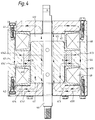
- An actuator rod 46 is reciprocable with an armature 45 through openings in a pair of parallel end plates constituting pole pieces 41, 42, whose inner faces act as end stops for the armature 45.
- the pole pieces 41, 42 are connected by side plates 43, 44 which, with the pole pieces, support two fixed, annular, coaxial electromagnetic coils 48, 49 adjacent respective ends of the armature 45, and a fixed, centrally-disposed, coaxial, cylindrical permanent magnet 410.
- the permanent magnet 410 extends axially over a central region of the armature 45 at all positions of the armature, and it is radially polarised as shown (S-N; N-S).
- the magnet is of neodymium-boron-iron, although another rare-earth magnetic material such as samarium-cobalt could be used especially where high temperatures are likely to be encountered.
- the magnet has the approximate dimensions of 70mm long by 60mm internal diameter, and produces a flux density of around 0.7 Webers per square metre at the centre and 1.7 Webers per square metre at its ends. Similar field strengths could alternatively be obtained from an AlNiCo magnet, but the properties of such a material are less advantageous in this particular application.
- the armature In use, with the armature at one stable position, as shown in Figure 4, it is held there by the permanent magnet which generates a low reluctance magnetic circuit 413, 414.
- the electromagnet coil 48 On energising the electromagnet coil 48 nearer the other end of the armature to produce a magnetic field 4131, 4141 in the sense shown, the flux of the original, low reluctance magnetic circuit 413, 414 is diverted, or, in a sense, opposed and cancel led, so that the flux density at the interface 411 of the armature and its end strip is substantially reduced, destabilising the armature.
- the flux is increased across the air gap 412 (approximately 14mm in this example) between the armature and the other of its end stops 41, tending to attract the armature towards its opposite stable position.
- the relatively small amount of magnetic flux 4132, 4142 generated by the electromagnet coil and passing through the permanent magnet is such as to maintain its magnetism, not to demagnetise the permanent magnet. More flux 4131, 4141 from the electromagnet coil 48 passes through the lower end plate 42 than through the relatively high-reluctance permanent magnet via path 4132, 4142.
- Movement of the armature from its other stable position is achieved by energising the other electromagnet coil 49 in the same sense, thus similarly avoiding demagnetisation of the permanent magnet 410.
- the configuration of the permanent magnet is cylindrical or annular in this example, other tubular configurations are feasible, including ones which are rotationally asymmetric about the longitudinal axis.
- the magnet should be tubular in the sense that it provides a longitudinal passage for the armature.
- the magnet could be formed as a unitary structure or segmented.
- the actuator efficiency and the way in which it is employed on the Auto recloser needs to be optimised.
- One or more of the following techniques may be used to tailor the basic actuator to the required application.
- the static force to hold the interrupters in the closed position may be 3 times greater than the static force to hold the interrupters in the open position.
- the armature 45 whilst in transit from one stable position to the other be preferentially biased in one direction due to the permanent magnet alone. This could be necessary to avoid a meta-stable position occurring at an undesirable point in the travel or to efficiently drive the armature over an increased distance with the required force/displacement.
- emfs may be produced by either transformer action as has been described above with reference to Figure 3 from the current in the opposing coil or be generated in both coils by the movement of the armature.
- the resultant current will circulate in any low impedance path in parallel with the coils, (e.g. free-wheeling diode as shown in Figure 3).
- the design incorporates a method of increasing the impedance of this path, thus significantly reducing the value of the current and associated field.
- An example is use of the resistors shown in Figure 3.
- a further advantage of this increased impedance is that the reduction of circulating current will reduce opposition to movement of the armature when the coils are not energised.
- an auto-recloser circuit breaker principally for outdoor use but optionally for indoor applications, comprises, for each of three phases, a vacuum interrupter 610 housed in an EPDM rubber body 611.
- a single kiosk 612 houses the bistable magnetic actuator 613 of the type described above with reference to Figures 4 and 5, which operates all three vacuum interrupters 610 by way of a cross beam 614.
- the kiosk may rest on the ground, or else it may be mounted on a plinth or on a pole 615 as shown.
- the interrupter contacts are maintained in either the closed or the open position by the magnetic actuator.
- the fixed contact is connected to an upper line terminal 616 integral with a support casing, and the movable contact to an axially reciprocable transfer contact 617 which slides within a ring-shaped fixed contact 618 connected to a side-mounted terminal 619.
- the side terminal 619 consists of a rod projecting transversely from an insulating bushing forming part of the rubber body 611.
- the body 611 has a number of rain sheds 612 moulded onto its outer surface to increase external creepage and flashover distances across the interrupter and from the interrupter 610 to the supporting kiosk 612 which is at earth potential.
- the inner surface of the EPDM rubber body 611 is lined by a reinforced plastics tube which provides mechanical strength and separates the EPDM rubber from a dielectric liquid or gaseous insulating medium 620 in which the internal parts are immersed.
- the medium 620 is SF6 gas, supplied through a filling valve.
- a protective current transformer core and toroidally wound secondary winding 621 surround the side-mounted line terminal 619, and are encapsulated in the bushing 622 integral with the rubber body 611.
- the output from the current transformer is connected by a line 623, encapsulated in the rubber body 611, to the actuator assembly 613.
- the single actuator 613 is in line with the three vacuum interrupters, which it drives by way of a purely mechanical, direct linkage.
- the linkage comprises an axial, insulating drive rod 624 for each interrupter connected at its upper end to the sliding contact 617 and at its lower end, via surrounding spring 625 in the cross beam 614, via a lost motion device to the actuator shaft.
- the rods extend axially through the base of the rubber body 611 and through the roof of the kiosk 612, which is sealed against the underside of the base of the rubber body 611.
- the space within the kiosk may communicate with that within the rubber body 611, avoiding the need for the potentially leaky mechanical gas seals.
- the electronic protection relay which is located with the two lithium sulphur dioxide batteries in a housing 626 responds to a signal from the current transformer 621 indicative of either an over-current condition, a short circuit or an earth fault, to send an appropriate short pulse to activate the actuator.
- the relay includes a sequence timer for the auto-reclose function, which causes the interrupter contacts to reclose after a predetermined interval following circuit interruption. If the fault is not cured and the circuit is interrupted a second time, the circuit recloses after a predetermined interval; and so on for the auto-reclose
- each interrupter moving contact is driven concentric with its body envelope.
- To achieve this bearings are required at each end of the insulator drive rod.
- a simple method of achieving low friction, jam free operation - without the need for a high precision mechanism is achieved as follows.
- the closing spring 625 is in a machined U-shape pocket on the beam 614 and the drive shaft 624 passes through a large clearance hole 627 in the beam.
- the drive rod is maintained concentric by the spring and its collar. There is no contact between the drive shaft and the beam which may jam or cause friction.
- the exemplary drive mechanism helps to achieve a low static loading on the actuator of about 60kg due to each interrupter, so that with safety margins the maximum toatl loading on the actuator is in the range 300kg to 350kg which can be accommodated by the 96V lithium sulphur dioxide battery as described above.
Abstract
Description
- This invention relates to auto-reclosers.
- A pole mounted auto-recloser is a high voltage pole-top mounted reclosing circuit-breaker which is used to protect high voltage overhead electrical power distribution lines. The function of the recloser is to reduce system interruption to a minimum if a transient or permanent fault should occur on the sytem. The recloser senses fault current in the main HV circuit, that is in the three phase power line, and opens its three main contacts to interrupt the current. After a short period known as the dead-time the recloser will reclose. Most faults are transient in nature and will clear during the dead-time so that when the unit recloses the HV supply is restored. If the fault has not cleared the recloser senses the fault current and again opens to interrupt it. The recloser can attempt to reclose up to say three times. If the fault is permanent after a predetermined number of trips it will remain open thereby isolating the faulty section of line.
- An inherent problem with pole mounted reclosers is that such equipment is typically situated in remote locations. For this reason they have to be very reliable with very long intervals between maintenance periods. Also there will be no local power supply for opening and closing the recloser main contacts or for supplying the elctronic protection and control unit part of the recloser.
- There are many solutions to the problem of power supply all of which have involved obtaining power either directly or indirectly from the HV supply. This presents problems when one considers the fact that there will be a fault on the HV supply at the very moment when the HV supply is required to operate the recloser; also it is not possible to close the recloser if there is no HV supply.
- According to the invention, there is provided an auto-recloser circuit-breaker for use with a three phase high voltage electrical power distribution line, the auto-recloser including (a) three vacuum interrupters for connection one in each phase of the power line, (b) current transformer means for sensing current on the power line, (c) an electronic protection relay having inputs connected to said current transformer means and outputs for providing auto-reclose control pulses, (d) a first, comparatively low voltage, power supply connected for operating the protection relay, (e) operating means for opening and closing the interrupters responsive to the control pulses from the relay, the operating means including a single bistable magnetic actuator and a drive mechanism connected between the three interrupters and the magnetic actuator, the magnetic actuator having a reciprocable armature, two electromagnetic coils each for moving the armature to one of two positions, and a permanent magnet for holding the armature in either position, and (f) a second, comparatively high voltage, power supply for energising the magnetic actuator, this second power supply being connected to each magnetic actuator coil via a respective electronic switch responsive to the auto-reclose control pulses from the relay; wherein the first and second power supplies are provided by lithium sulphur dioxide battery means, the auto-recloser being powered solely by this battery means and not by the high voltage power line.
- The first and second power supplies may be provided each from a separate lithium sulphur dioxide battery.
- The drive mechanism may include three drive rods, one said rod for operating each interrupter, and with the three drive rods arranged to be driven together directly by said reciprocable armature of said magnetic actuator in line with the movement of said armature. In this case, the three drive rods maybe linked to the actuator by a single cross-beam, each rod being maintained in line by a spring in a pocket in the beam without contact between the rod and the beam.
- The magnetic circuit in the actuator due to the permanent magnet maybe arranged to provide a static force to hold the armature in its stable position corresponding to the interrupters being closed greater than the static force to hold the armature in the stable position corresponding to the interrupters being open.
- The armature and/or a pole piece in the actuator maybe shaped to modify the flux in an air gap between them so that in response to a control pulse to operate the actuator to the open position of the interrupters the armature is preferentially biased by the permanent magnet towards that open position.
- A parallel path circuit maybe provided for each actuator coil to circulate current due to emfs generated in the coils resulting from actuation, and with impedance provided in each said parallel path circuit to reduce opposition to movement of the armature due to such current.
- The protection relay may include wake-up and power-down circuit means to reduce consumption of battery energy. In this case, the wake-up circuit means may include a comparator and a latch in CMOS to minimise the battery energy which is continuously consumed by these components.
- The self powered recloser according to the invention has solved the following design problems:
- 1. A self contained stored energy supply capable of supplying the recloser for a minimum period of 10 years and 10,000 operations is required.
- 2. A very efficient method of opening and closing the main interrupter contacts is required in order to maximise the number of operations available from a given energy source.
- 3. The electronic protection must also be capable of operating over a ten year period from a self contained energy source.
- Important features of the exemplary embodiment to be described below are as follows:
- 1. The electronic protection and control unit, the protection relay, is designed to draw a very small current from a 12V Lithium Sulphur Dioxide battery in the order of 15 uA under normal conditions by extensive use of CMOS technology in particular in a wake-up circuit.
- 2. The design of the drive system, the interrupters used and the construction of magnetic actuator have been optimised in order to use the minimum energy possible from a primary battery supply.
- 3. A Lithium Sulphur Dioxide battery system is used. Important features of the LSO2 battery system for use with the recloser are:
- 3.1 Long shelf life; self discharge rate lower than any other battery system suitable for at least 10 years maintenance free life.
- 3.2 Very high energy density; stored energy sufficient for 10,000 operations.
- 3.3 Wide operating temperature range; -55C to +70C
- 3.4 High discharge current capability
- An exemplary embodiment of the invention will now be described with reference to the accompanying drawings comprising Figures 1 to 7.
- Referring now to Figure 1, there is shown a schematic diagram of an auto-recloser circuit breaker for use with a three phase high voltage electrical power distribution line. The three phase power line is shown extending through the auto-recloser from three supply side terminals to three corresponding load side terminals. The high voltage could typically be 15kV and the normal load current typically less than 1kA. Three vacuum interrupters are provided for connection one in each phase of the power line as shown. Three ring current transformers are provided for sensing current on the power line. An electronic protection relay has inputs connected to these current transformers and outputs for providing auto-reclose control pulses. A 12 volt Lithium Sulphur Dioxide battery provides a power supply connected for operating the protection relay. Operating means for opening and closing the vacuum interrupters responsive to the control pulses from the relay include a single bistable magnetic actuator and a drive mechanism (shown by the single dotted line) connected between the three interrupters and the magnetic actuator. The magnetic actuator (to be later described in detail with reference to Figures 4 and 5) has a reciprocable armature, two electromagnetic coils (shown as "open" and "close" in Figure 1) each for moving the armature to one of two positions, and a permanent magnet for holding the armature in either position.
- A 96 volt lithium sulphur dioxide battery is provided for energising the magnetic actuator, this battery being connected to each magnetic actuator coil via a respective electronic switch (output FET as shown) responsive to the auto-reclose control pulses from the relay. Thus the recloser is powered solely by the two batteries and not by the high voltage power line.
- A microprocessor in the relay provides the control pulses to the output FETs to control the opening (tripping) and closing operations of the recloser. An auxiliary switch (shown in Figure 1) is connected to the recloser main drive shaft and signals the position of the recloser to the microprocessor which will terminate the trip or close signal accordingly. By means of parallel path circuit means connected to each actuator coil (as will be described later in detail with reference to Figure 3), the close and trip current pulses are controlled to the minimum length necessary to ensure correct operation thereby minimising the amount of energy taken from the 96 volt battery. The current required to be supplied by this battery will be between approximately 25A and 30A, which comes as a requirement from the design of the magnetic actuator and the load on the actuator from the interrupter drive mechanism. The required voltage for this battery, according to temperature conditions of use, could be between say 90-105V.
- The configuration and operation of the electronic protection relay will now be described in detail with reference to Figures 1 and 2. The current transformers on the three phase power line will bring the normal load current down to below say approximately 100A at the inputs to the relay. The current transformers within the relay will further bring these currents down to below say approximately 100mA. Figure 2 shows four current transformers in the relay. The outputs of these four current transformers are each passed through a rectifier circuit to a burdens circuit. The burdens circuits, as shown in Figure 2, can have switched in a selected parallel resistors to translate the rectified current at whatever protection level is required to a predetermined voltage output, for example a protection level of 100mA is translated to an output from the burdens circuits of 0.1 volts. In a manner, not shown, this switching in of resistors in the burdens circuits is controlled from the microprocessor. The 12 volt lithium sulphur dioxide battery continuously supplies a wake-up circuit including a reference voltage circuit, four comparators, an OR gate and a latch. These circuit components are in CMOS and continuously take only a very small current (15µA) from the 12 volt battery. This battery can sustain this load for greater than its expected life of 10 years. The reference voltage circuit consumes only say 1-1.5µA from the 12V battery and supplies a reference voltage of say 0.1 volt to one input of each of the four comparators. The outputs from the burdens circuits are connected respectively to the other inputs of the comparators. If any of the four comparators detects a particular fault condition on the power line as determined by the output from the corresponding burdens circuit then, via the OR gate, the latch is set and provides a wake-up signal to power up the microprocessor and the A/D converter which is provided between the burdens circuit outputs and the microprocessor. There is actually a voltage regulator (not shown) between the 12V battery and the microprocessor which is thereby powered from 5 volts. Although the A/D convertor is shown here separately it is in fact, together with a multiplexer for scanning all the burdens outputs, integrated with the microprocessor in a microcontroller. The value of the power line overload as outputs from the burdens circuits is measured by the A/D converter and determines the tripping time set by the microprocessor. Thus a massive overload requires the lowest possible tripping time, i.e. the vacuum interrupters should be tripped open straight away. For a small overload a certain length of tripping time is set; for example a 50% overload could provide a 1


- Figure 3 shows the two actuator coils connected to the 96 volt Lithium sulphur dioxide battery via the FETs as has been shown in Figure 2 and a diode and resistor in series with each other and in parallel with each coil.
- The diodes are included to protect the FETs at turn-off. The two solenoid coils which are highly inductive produce a large back-emf when the FETs turn off (L di/dt ). Without the diodes this voltage would appear across the FETs. With the diodes in the circuit the voltage is limited to the battery voltage as the back emf causes current to flow around the local loop until the energy stored has exponentially decayed away.
- However, this can cause problems with the magnetic actuator. When the close coil is energised, transformer action causes a current to be induced in the trip-soleniod coil around the diode circuit even though the FET is turned off. This current causes the trip coil to oppose the intended closing operation and more current is drawn from the 96 volt Lithium battery. We have combatted this by putting a resistor in series with the diode which reduces this effect to a negligable level whilst keeping the back emf to below the rating of the FETs. The use of resistors in this manner has given about 25% increase in efficiency with a consequent beneficial effect on battery operation
- The magnetic actuator build up and a description of its operation follows with reference to Figures 4 and 5.
- An
actuator rod 46 is reciprocable with anarmature 45 through openings in a pair of parallel end plates constitutingpole pieces armature 45. Thepole pieces side plates electromagnetic coils armature 45, and a fixed, centrally-disposed, coaxial, cylindricalpermanent magnet 410. - The
permanent magnet 410, extends axially over a central region of thearmature 45 at all positions of the armature, and it is radially polarised as shown (S-N; N-S). In this example, the magnet is of neodymium-boron-iron, although another rare-earth magnetic material such as samarium-cobalt could be used especially where high temperatures are likely to be encountered. The magnet has the approximate dimensions of 70mm long by 60mm internal diameter, and produces a flux density of around 0.7 Webers per square metre at the centre and 1.7 Webers per square metre at its ends. Similar field strengths could alternatively be obtained from an AlNiCo magnet, but the properties of such a material are less advantageous in this particular application. - In use, with the armature at one stable position, as shown in Figure 4, it is held there by the permanent magnet which generates a low reluctance
magnetic circuit electromagnet coil 48 nearer the other end of the armature to produce amagnetic field magnetic circuit interface 411 of the armature and its end strip is substantially reduced, destabilising the armature. - At the same time, the flux is increased across the air gap 412 (approximately 14mm in this example) between the armature and the other of its end stops 41, tending to attract the armature towards its opposite stable position. Also, the relatively small amount of
magnetic flux 4132, 4142 generated by the electromagnet coil and passing through the permanent magnet is such as to maintain its magnetism, not to demagnetise the permanent magnet.More flux electromagnet coil 48 passes through thelower end plate 42 than through the relatively high-reluctance permanent magnet viapath 4132, 4142. - Movement of the armature from its other stable position is achieved by energising the
other electromagnet coil 49 in the same sense, thus similarly avoiding demagnetisation of thepermanent magnet 410. - Although the configuration of the permanent magnet is cylindrical or annular in this example, other tubular configurations are feasible, including ones which are rotationally asymmetric about the longitudinal axis. The magnet should be tubular in the sense that it provides a longitudinal passage for the armature. The magnet could be formed as a unitary structure or segmented.
- For ergonomic utilization of the battery, the actuator efficiency and the way in which it is employed on the Auto recloser needs to be optimised.
- One or more of the following techniques may be used to tailor the basic actuator to the required application.
- In most cases it is desirable that the magnetic circuit due to the permanent magnet results in static forces which differ in the two stable positions. The static force to hold the interrupters in the closed position may be 3 times greater than the static force to hold the interrupters in the open position.
- This may be achieved by arranging the respective magnetic circuits such that the chosen value of reluctance will give the required flux level and hold-on force.
- A simple means of achieving this will be by adding a
non-ferrous washer 47 of required thickness over therod 46. Many alternative methods will be possible but the effect of these on the dynamic operation of the actuator must be considered. - It may be required that the
armature 45, whilst in transit from one stable position to the other be preferentially biased in one direction due to the permanent magnet alone. This could be necessary to avoid a meta-stable position occurring at an undesirable point in the travel or to efficiently drive the armature over an increased distance with the required force/displacement. - Several methods of achieving this are proposed, which involve shaping the
pole pieces armature 45 such that the flux will be modified in the required air gap. - 1. Interlocking conical pole piece and armature acting such that the cross sectional area in the direction of the flux is increased (Figure 5A).
- 2. Interlocking slotted pole piece and armature acting such that the apparent air gap in the direction of the flux is reduced. (Figure 58)
- 3. Cutting a groove around the circumference of the armature body in the vicinity of the
magnet 410, such as to vary the reluctance of the circuit dependent upon armature position. (Figure 5C) - These emfs may be produced by either transformer action as has been described above with reference to Figure 3 from the current in the opposing coil or be generated in both coils by the movement of the armature. The resultant current will circulate in any low impedance path in parallel with the coils, (e.g. free-wheeling diode as shown in Figure 3).
- The design incorporates a method of increasing the impedance of this path, thus significantly reducing the value of the current and associated field. An example is use of the resistors shown in Figure 3.
- A further advantage of this increased impedance is that the reduction of circulating current will reduce opposition to movement of the armature when the coils are not energised.
- Referring now to Figure 6, an auto-recloser circuit breaker, principally for outdoor use but optionally for indoor applications, comprises, for each of three phases, a
vacuum interrupter 610 housed in anEPDM rubber body 611. Asingle kiosk 612 houses the bistablemagnetic actuator 613 of the type described above with reference to Figures 4 and 5, which operates all threevacuum interrupters 610 by way of across beam 614. - The kiosk may rest on the ground, or else it may be mounted on a plinth or on a
pole 615 as shown. - The interrupter contacts are maintained in either the closed or the open position by the magnetic actuator. The fixed contact is connected to an
upper line terminal 616 integral with a support casing, and the movable contact to an axiallyreciprocable transfer contact 617 which slides within a ring-shapedfixed contact 618 connected to a side-mountedterminal 619. Theside terminal 619 consists of a rod projecting transversely from an insulating bushing forming part of therubber body 611. Thebody 611 has a number of rain sheds 612 moulded onto its outer surface to increase external creepage and flashover distances across the interrupter and from theinterrupter 610 to the supportingkiosk 612 which is at earth potential. The inner surface of theEPDM rubber body 611 is lined by a reinforced plastics tube which provides mechanical strength and separates the EPDM rubber from a dielectric liquid or gaseous insulatingmedium 620 in which the internal parts are immersed. In this example, the medium 620 is SF₆ gas, supplied through a filling valve. - A protective current transformer core and toroidally wound secondary winding 621 surround the side-mounted
line terminal 619, and are encapsulated in thebushing 622 integral with therubber body 611. The output from the current transformer is connected by aline 623, encapsulated in therubber body 611, to theactuator assembly 613. - The
single actuator 613 is in line with the three vacuum interrupters, which it drives by way of a purely mechanical, direct linkage. The linkage comprises an axial, insulatingdrive rod 624 for each interrupter connected at its upper end to the slidingcontact 617 and at its lower end, via surroundingspring 625 in thecross beam 614, via a lost motion device to the actuator shaft. The rods extend axially through the base of therubber body 611 and through the roof of thekiosk 612, which is sealed against the underside of the base of therubber body 611. - Where the
drive rods 624 andinterrupters 610 are insulated by a gas, the space within the kiosk may communicate with that within therubber body 611, avoiding the need for the potentially leaky mechanical gas seals. - The electronic protection relay which is located with the two lithium sulphur dioxide batteries in a
housing 626 responds to a signal from thecurrent transformer 621 indicative of either an over-current condition, a short circuit or an earth fault, to send an appropriate short pulse to activate the actuator. As has been described above with reference to Figures 1 and 2, the relay includes a sequence timer for the auto-reclose function, which causes the interrupter contacts to reclose after a predetermined interval following circuit interruption. If the fault is not cured and the circuit is interrupted a second time, the circuit recloses after a predetermined interval; and so on for the auto-reclose - sequence. A detail of the drive mechanism shown in Figure 6 will now be described in more detail with reference to Figure 7.
- It is a requirement that each interrupter moving contact is driven concentric with its body envelope. To achieve this bearings are required at each end of the insulator drive rod. A simple method of achieving low friction, jam free operation - without the need for a high precision mechanism is achieved as follows. The
closing spring 625 is in a machined U-shape pocket on thebeam 614 and thedrive shaft 624 passes through alarge clearance hole 627 in the beam. Thus the drive rod is maintained concentric by the spring and its collar. There is no contact between the drive shaft and the beam which may jam or cause friction. - The exemplary drive mechanism helps to achieve a low static loading on the actuator of about 60kg due to each interrupter, so that with safety margins the maximum toatl loading on the actuator is in the range 300kg to 350kg which can be accommodated by the 96V lithium sulphur dioxide battery as described above.
Claims (9)
- An auto-recloser circuit-breaker for use with a three phase high voltage electrical power distribution line, the auto-recloser including (a) three vacuum interrupters for connection one in each phase of the power line, (b) current transformer means for sensing current on the power line, (c) an electronic protection relay having inputs connected to said current transformer means and outputs for providing auto-reclose control pulses, (d) a first, comparatively low voltage, power supply connected for operating the protection relay, (e) operating means for opening and closing the interrupters responsive to the control pulses from the relay, the operating means including a single bistable magnetic actuator and a drive mechanism connected between the three interrupters and the magnetic actuator, the magnetic actuator having a reciprocable armature, two electromagnetic coils each for moving the armature to one of two positions, and a permanent magnet for holding the armature in either position, and (f) a second, comparatively high voltage, power supply for energising the magnetic actuator, this second power supply being connected to each magnetic actuator coil via a respective electronic switch responsive to the auto-reclose control pulses from the relay; wherein the first and second power supplies are provided by lithium sulphur dioxide battery means, the auto-recloser being powered solely by this battery means and not by the high voltage power line.
- An auto-recloser as claimed in Claim 1, in which the first and second power supplies are provided each from a separate lithium sulphur dioxide battery.
- An auto-recloser as claimed in Claim 1 or claim 2, in which the drive mechanism includes three drive rods, one said rod for operating each interrupter, and in which the three drive rods are arranged to be driven together directly by said reciprocable armature of said magnetic actuator in line with the movement of said armature.
- An auto-recloser as claimed in Claim 3, in which the drive rods are linked to the actuator by a single cross-beam, each rod being maintained in line by a spring in a pocket in the beam without contact between the rod and the beam.
- An auto-recloser as claimed in any one of claims 1 to 4, in which the magnetic circuit in the actuator due to the permanent magnet provides a static force to hold the armature in its stable position corresponding to the interrupters being closed greater than the static force to hold the armature in the stable position corresponding to the interrupters being open.
- An auto-recloser as claimed in anyone of claims 1 to 5, in which the armature and/or a pole piece in the actuator are shaped to modify the flux in an air gap between them so that in response to a control pulse to operate the actuator to the open position of the interrupters the armature is preferentially biased by the permanent magnet towards that open position.
- An auto-recloser as claimed in my previous claim, in which a parallel path circuit is provided for each actuator coil to circulate current due to emfs generated in the coils resulting from actuation, and in which impedance is provided in each said parallel path circuit to reduce opposition to movement of the armature due to such current.
- An auto-recloser as claimed in any previous claim, in which the protection relay includes wake-up and power-down circuit means to reduce consumption of battery energy.
- An auto-recloser as claimed in claim 8, in which the wake-up circuit means includes a comparator and a latch in CMOS to minimise the battery energy which is continuously consumed by these components.
Applications Claiming Priority (2)
| Application Number | Priority Date | Filing Date | Title |
|---|---|---|---|
| GB9215405 | 1992-07-20 | ||
| GB929215405A GB9215405D0 (en) | 1992-07-20 | 1992-07-20 | Auto-reclosers |
Publications (2)
| Publication Number | Publication Date |
|---|---|
| EP0580285A2 true EP0580285A2 (en) | 1994-01-26 |
| EP0580285A3 EP0580285A3 (en) | 1995-05-03 |
Family
ID=10719000
Family Applications (1)
| Application Number | Title | Priority Date | Filing Date |
|---|---|---|---|
| EP93304614A Withdrawn EP0580285A3 (en) | 1992-07-20 | 1993-06-14 | Auto-reclosers. |
Country Status (6)
| Country | Link |
|---|---|
| US (1) | US5452172A (en) |
| EP (1) | EP0580285A3 (en) |
| AU (1) | AU662824B2 (en) |
| BR (1) | BR9302913A (en) |
| GB (2) | GB9215405D0 (en) |
| MX (1) | MX9304342A (en) |
Cited By (15)
| Publication number | Priority date | Publication date | Assignee | Title |
|---|---|---|---|---|
| FR2720200A1 (en) * | 1994-05-20 | 1995-11-24 | Gen Electric | Digital control unit for circuit breaker protecting against overcurrents |
| US5585611A (en) * | 1994-03-31 | 1996-12-17 | Abb Power T&D Company Inc. | Interrupter assembly |
| US5912604A (en) * | 1997-02-04 | 1999-06-15 | Abb Power T&D Company, Inc. | Molded pole automatic circuit recloser with bistable electromagnetic actuator |
| WO2001065581A1 (en) * | 2000-03-02 | 2001-09-07 | Cruise, Rupert, John | A magnetic actuator |
| EP1132929A1 (en) * | 2000-03-10 | 2001-09-12 | ABBPATENT GmbH | Permanent magnetic drive for an electrical switching device |
| US6933827B2 (en) * | 2002-11-15 | 2005-08-23 | Mitsubishi Denki Kabushiki Kaisha | Actuator, method of manufacturing the actuator and circuit breaker provided with the actuator |
| EP1619769A1 (en) * | 2003-03-11 | 2006-01-25 | TMT & D Corporation | Dc power supply system and switch |
| WO2012096863A1 (en) * | 2011-01-12 | 2012-07-19 | Schneider Electric USA, Inc. | System and method for monitoring current drawn by a protected load in a self-powered electronic protection device |
| WO2013169716A1 (en) * | 2012-05-07 | 2013-11-14 | S&C Electric Company | Dropout recloser |
| DE102014219772A1 (en) | 2014-09-30 | 2016-03-31 | Siemens Aktiengesellschaft | Vacuum interrupter |
| DE102015200135A1 (en) | 2015-01-08 | 2016-07-14 | Siemens Aktiengesellschaft | Coupling member for an electrical switching device, in particular a vacuum interrupter |
| DE102015200112A1 (en) | 2015-01-08 | 2016-07-14 | Siemens Aktiengesellschaft | Vacuum interrupter |
| EP3200300A4 (en) * | 2014-09-26 | 2018-05-30 | Seari Electric Technology Co., Ltd. | Electronic trip unit protection device and protection method |
| CN109690718A (en) * | 2016-08-26 | 2019-04-26 | 三菱电机株式会社 | The driving circuit of electromagnetic operating mechanism |
| WO2019244034A1 (en) * | 2018-06-20 | 2019-12-26 | Celsa S.A.S. | Device for the automatic interruption and reconnection of medium-voltage circuits which can be installed in interchangeable bases |
Families Citing this family (25)
| Publication number | Priority date | Publication date | Assignee | Title |
|---|---|---|---|---|
| GB2305557B (en) * | 1995-09-19 | 2000-02-23 | Gec Alsthom Ltd | Method for depassivating a lithium battery |
| MY119298A (en) * | 1996-09-13 | 2005-04-30 | Cooper Ind Inc | Encapsulated vacuum interrupter and method of making same |
| US6753493B2 (en) * | 2001-06-01 | 2004-06-22 | Hubbell Incorporated | Electrical circuit interrupting device |
| US6836121B2 (en) * | 2001-06-06 | 2004-12-28 | Abb Inc. | Apparatus for controlling a magnetically actuated power switching device and method of controlling the same |
| US7403130B2 (en) * | 2004-08-20 | 2008-07-22 | Cooper Technologies Company | Removing an automatic circuit recloser from service prior to battery failure |
| US7869170B2 (en) * | 2006-07-14 | 2011-01-11 | Susan Jean Walker Colsch | Method and system for time synchronized trip algorithms for breaker self protection |
| KR100780706B1 (en) * | 2006-08-17 | 2007-11-30 | 엘에스산전 주식회사 | Super conductive current limiter |
| BR112013001974A2 (en) * | 2010-07-26 | 2018-08-28 | Tyco Electronics Corp | controller circuit including a switching mode power converter and automatic recloser using the same |
| KR101147202B1 (en) * | 2010-10-13 | 2012-05-25 | 삼성에스디아이 주식회사 | Power storage apparatus |
| US8675325B2 (en) * | 2010-10-20 | 2014-03-18 | Schneider Electric USA, Inc. | Electronic circuit breaker with alternate mode of operation using auxiliary power source |
| US8497446B1 (en) | 2011-01-24 | 2013-07-30 | Michael David Glaser | Encapsulated vacuum interrupter with grounded end cup and drive rod |
| CN103325627A (en) * | 2012-03-20 | 2013-09-25 | 深圳市金博联电力技术有限公司 | Fast and intelligent 10KV pole-mounted breaker |
| US9761394B2 (en) | 2013-02-08 | 2017-09-12 | Hubbell Incorporated | Current interrupter for high voltage switches |
| CN103123882B (en) * | 2013-02-26 | 2015-02-11 | 滁州学院 | Intelligent controller of bistable permanent-magnet vacuum circuit breaker |
| DE102013013585B4 (en) * | 2013-06-20 | 2020-09-17 | Rhefor Gbr | Self-holding magnet with particularly low electrical tripping power |
| US9343216B2 (en) * | 2013-09-02 | 2016-05-17 | Glen A. Robertson | Energy efficient bi-stable permanent magnet actuation system |
| US9514872B2 (en) * | 2014-12-19 | 2016-12-06 | General Electric Company | Electromagnetic actuator and method of use |
| FR3069698B1 (en) * | 2017-07-26 | 2019-08-16 | Schneider Electric Industries Sas | COMMANDABLE CURRENT CURRENT APPARATUS AND ELECTRICAL ASSEMBLY COMPRISING SAID APPARATUS |
| US10297376B2 (en) * | 2017-09-25 | 2019-05-21 | The United States Of America As Represented By The Administrator Of Nasa | Bi-stable pin actuator |
| KR102531873B1 (en) * | 2019-01-31 | 2023-05-11 | 에스 앤드 시이 일렉트릭 캄파니 | Multiple hammer-struck vacuum interrupter weld failures |
| EP4293694A3 (en) * | 2019-12-05 | 2024-03-27 | S&C Electric Company | Low energy reclosing pulse test system and method |
| NZ787711A (en) * | 2019-12-05 | 2022-07-01 | S & C Electric Co | Switch assembly with energy harvesting |
| EP4128303A4 (en) | 2020-03-31 | 2024-04-17 | Hubbell Inc | System and method for operating an electrical switch |
| EP4222768A1 (en) * | 2020-10-01 | 2023-08-09 | S&C Electric Company | Voltage readings using high voltage resistor across vacuum interrupter |
| US20220181866A1 (en) * | 2020-12-08 | 2022-06-09 | S&C Electric Company | Method for fast-detection of peak fault current |
Family Cites Families (8)
| Publication number | Priority date | Publication date | Assignee | Title |
|---|---|---|---|---|
| US3662220A (en) * | 1959-03-19 | 1972-05-09 | Mc Graw Edison Co | Time delay device |
| GB1216339A (en) * | 1967-04-25 | 1970-12-16 | Ass Elect Ind | Improvements relating to circuits for controlling the tripping of a circuit breaker |
| US4184186A (en) * | 1977-09-06 | 1980-01-15 | General Electric Company | Current limiting device for an electric power system |
| US4931896A (en) * | 1985-03-14 | 1990-06-05 | Cooper Industries, Inc. | Distribution line switchgear control with isolated cascaded power supplies |
| US4751606A (en) * | 1987-02-20 | 1988-06-14 | Westinghouse Electric Corp. | Circuit interrupter apparatus with a battery backup and reset circuit |
| US4876521A (en) * | 1987-08-25 | 1989-10-24 | Siemens Energy & Automation, Inc. | Tripping coil with flux shifting coil and booster coil |
| GB8819166D0 (en) * | 1988-08-12 | 1988-09-14 | Ass Elect Ind | Magnetic actuator & permanent magnet |
| US5117325A (en) * | 1990-01-23 | 1992-05-26 | Cooper Industries, Inc. | Controllable recloser for power line |
-
1992
- 1992-07-19 MX MX9304342A patent/MX9304342A/en unknown
- 1992-07-20 GB GB929215405A patent/GB9215405D0/en active Pending
-
1993
- 1993-06-14 GB GB9312209A patent/GB2269063B/en not_active Revoked
- 1993-06-14 EP EP93304614A patent/EP0580285A3/en not_active Withdrawn
- 1993-06-16 US US08/078,986 patent/US5452172A/en not_active Expired - Fee Related
- 1993-06-30 AU AU41663/93A patent/AU662824B2/en not_active Ceased
- 1993-07-19 BR BR9302913A patent/BR9302913A/en not_active IP Right Cessation
Non-Patent Citations (4)
| Title |
|---|
| A.D.SHEPHARD, S.E.LANE & J.S.STEWART: "A New Microprocessor Relay for Overhead Line Scada Applications", ELECTRONIC AND POWER, June 1984 (1984-06-01) |
| A.MICHEL: "Electromagnetic Actuators and Their Possible Use in Pole Mounted Switchgear", THE ELECTRICITY COUNCIL, CHIEF ENGINEERS' CONFERENCE, 27 January 1980 (1980-01-27) |
| GEC ALSTHOM 'OXR Pole Mounting Automatic Recloser System Voltages up to 24kV' |
| HAWKER SIDDELEY SWITCHGEAR 'BRUSH PMR 3, SF6 Pole Mounted Auto Recloser' |
Cited By (29)
| Publication number | Priority date | Publication date | Assignee | Title |
|---|---|---|---|---|
| US5585611A (en) * | 1994-03-31 | 1996-12-17 | Abb Power T&D Company Inc. | Interrupter assembly |
| FR2720200A1 (en) * | 1994-05-20 | 1995-11-24 | Gen Electric | Digital control unit for circuit breaker protecting against overcurrents |
| US5912604A (en) * | 1997-02-04 | 1999-06-15 | Abb Power T&D Company, Inc. | Molded pole automatic circuit recloser with bistable electromagnetic actuator |
| WO2001065581A1 (en) * | 2000-03-02 | 2001-09-07 | Cruise, Rupert, John | A magnetic actuator |
| EP1132929A1 (en) * | 2000-03-10 | 2001-09-12 | ABBPATENT GmbH | Permanent magnetic drive for an electrical switching device |
| US6933827B2 (en) * | 2002-11-15 | 2005-08-23 | Mitsubishi Denki Kabushiki Kaisha | Actuator, method of manufacturing the actuator and circuit breaker provided with the actuator |
| EP1619769A1 (en) * | 2003-03-11 | 2006-01-25 | TMT & D Corporation | Dc power supply system and switch |
| EP1619769A4 (en) * | 2003-03-11 | 2009-08-26 | Toshiba Kk | Dc power supply system and switch |
| WO2012096863A1 (en) * | 2011-01-12 | 2012-07-19 | Schneider Electric USA, Inc. | System and method for monitoring current drawn by a protected load in a self-powered electronic protection device |
| US8854032B2 (en) | 2011-01-12 | 2014-10-07 | Schneider Electric USA, Inc. | System and method for monitoring current drawn by a protected load in a self-powered electronic protection device |
| WO2013169716A1 (en) * | 2012-05-07 | 2013-11-14 | S&C Electric Company | Dropout recloser |
| EP3032560A1 (en) * | 2012-05-07 | 2016-06-15 | S & C Electric Co. | Bistable actuator device |
| US11916369B2 (en) | 2012-05-07 | 2024-02-27 | S&C Electric Company | Dropout recloser |
| AU2022203251B2 (en) * | 2012-05-07 | 2023-05-25 | S&C Electric Company | Dropout recloser |
| US11322927B2 (en) | 2012-05-07 | 2022-05-03 | S&C Electric Company | Dropout recloser |
| EP3200300A4 (en) * | 2014-09-26 | 2018-05-30 | Seari Electric Technology Co., Ltd. | Electronic trip unit protection device and protection method |
| DE102014219772A1 (en) | 2014-09-30 | 2016-03-31 | Siemens Aktiengesellschaft | Vacuum interrupter |
| WO2016050490A1 (en) | 2014-09-30 | 2016-04-07 | Siemens Aktiengesellschaft | Vacuum interrupter |
| DE102015200135A1 (en) | 2015-01-08 | 2016-07-14 | Siemens Aktiengesellschaft | Coupling member for an electrical switching device, in particular a vacuum interrupter |
| US10032581B2 (en) | 2015-01-08 | 2018-07-24 | Siemens Aktiengesellschaft | Coupling element for an electric switching device |
| CN107112150B (en) * | 2015-01-08 | 2019-03-22 | 西门子公司 | Coupled connection mechanism for electric switching system, especially vacuum switch tube |
| CN107112150A (en) * | 2015-01-08 | 2017-08-29 | 西门子公司 | Coupled connection mechanism for electric switching system, especially vacuum switch tube |
| WO2016110430A1 (en) | 2015-01-08 | 2016-07-14 | Siemens Aktiengesellschaft | Coupling element for an electric switching device, in particular a vacuum switching tube |
| DE102015200112A1 (en) | 2015-01-08 | 2016-07-14 | Siemens Aktiengesellschaft | Vacuum interrupter |
| CN109690718A (en) * | 2016-08-26 | 2019-04-26 | 三菱电机株式会社 | The driving circuit of electromagnetic operating mechanism |
| EP3506330A4 (en) * | 2016-08-26 | 2019-08-14 | Mitsubishi Electric Corporation | Electromagnetic operation mechanism drive circuit |
| CN109690718B (en) * | 2016-08-26 | 2020-04-24 | 三菱电机株式会社 | Drive circuit of electromagnetic operating mechanism |
| WO2019244034A1 (en) * | 2018-06-20 | 2019-12-26 | Celsa S.A.S. | Device for the automatic interruption and reconnection of medium-voltage circuits which can be installed in interchangeable bases |
| US20200412122A1 (en) * | 2018-06-20 | 2020-12-31 | Celsa S.A.S. | Device for the automatic interruption and reconnection of medium-voltage circuits which can be installed in interchangeable bases |
Also Published As
| Publication number | Publication date |
|---|---|
| MX9304342A (en) | 1994-04-29 |
| US5452172A (en) | 1995-09-19 |
| AU662824B2 (en) | 1995-09-14 |
| GB2269063B (en) | 1995-07-19 |
| BR9302913A (en) | 1994-02-22 |
| GB9215405D0 (en) | 1992-09-02 |
| AU4166393A (en) | 1994-01-27 |
| EP0580285A3 (en) | 1995-05-03 |
| GB2269063A (en) | 1994-01-26 |
| GB9312209D0 (en) | 1993-07-28 |
Similar Documents
| Publication | Publication Date | Title |
|---|---|---|
| AU662824B2 (en) | Auto-reclosers | |
| EP0354803A1 (en) | A bistable magnetic actuator and a circuit breaker | |
| US6009615A (en) | Method of manufacturing a bistable magnetic actuator | |
| US5912604A (en) | Molded pole automatic circuit recloser with bistable electromagnetic actuator | |
| Dullni | A vacuum circuit-breaker with permanent magnetic actuator for frequent operations | |
| EP3748662B1 (en) | Kinetic actuator for vacuum interrupter | |
| KR20080063122A (en) | Circuit breaker and method for switch the same | |
| EP1104067A3 (en) | Energy validation arrangement for a self-powered circuit breaker | |
| CN105280431A (en) | Grounding switch capable of extinguishing arc quickly through electromagnetic reluctance tension | |
| KR102531873B1 (en) | Multiple hammer-struck vacuum interrupter weld failures | |
| US5369542A (en) | Dual trip circuit for circuit breaker | |
| US11417481B2 (en) | Switch assembly | |
| JP2006236773A (en) | Circuit breaker | |
| US20140266520A1 (en) | Trip actuator for switch of electric power circuit | |
| EP4026155B1 (en) | Switch assembly with energy harvesting | |
| Dullni et al. | A vacuum circuit-breaker with permanent magnetic actuator and electronic control | |
| CN116631806A (en) | Deep fusion magnetic control type column vacuum circuit breaker | |
| CN202231403U (en) | Closing protection device of permanent magnetism operating mechanism | |
| EP0782759B1 (en) | Operating device for circuit breakers | |
| KR101884244B1 (en) | Electro-magnet actuator type protective back-up circuit breaker for power distribution line having the same | |
| RU67772U1 (en) | ELECTROMAGNETIC DRIVE OF CIRCUIT BREAKERS | |
| CN101702381B (en) | Design method of remanent magnetism mechanism of recombiner and remanent magnetism mechanism | |
| JPH019058Y2 (en) |
Legal Events
| Date | Code | Title | Description |
|---|---|---|---|
| PUAI | Public reference made under article 153(3) epc to a published international application that has entered the european phase |
Free format text: ORIGINAL CODE: 0009012 |
|
| AK | Designated contracting states |
Kind code of ref document: A2 Designated state(s): AT DE ES FR SE |
|
| PUAL | Search report despatched |
Free format text: ORIGINAL CODE: 0009013 |
|
| AK | Designated contracting states |
Kind code of ref document: A3 Designated state(s): AT DE ES FR SE |
|
| 17P | Request for examination filed |
Effective date: 19951101 |
|
| 17Q | First examination report despatched |
Effective date: 19970522 |
|
| STAA | Information on the status of an ep patent application or granted ep patent |
Free format text: STATUS: THE APPLICATION HAS BEEN WITHDRAWN |
|
| 18W | Application withdrawn |
Withdrawal date: 19970718 |