EP0580389A1 - Exhaust gas purification apparatus for an internal combustion engine - Google Patents
Exhaust gas purification apparatus for an internal combustion engine Download PDFInfo
- Publication number
- EP0580389A1 EP0580389A1 EP93305656A EP93305656A EP0580389A1 EP 0580389 A1 EP0580389 A1 EP 0580389A1 EP 93305656 A EP93305656 A EP 93305656A EP 93305656 A EP93305656 A EP 93305656A EP 0580389 A1 EP0580389 A1 EP 0580389A1
- Authority
- EP
- European Patent Office
- Prior art keywords
- temperature
- exhaust gas
- nox absorbent
- oxygen concentration
- fuel
- Prior art date
- Legal status (The legal status is an assumption and is not a legal conclusion. Google has not performed a legal analysis and makes no representation as to the accuracy of the status listed.)
- Granted
Links
Images


Classifications
-
- B—PERFORMING OPERATIONS; TRANSPORTING
- B01—PHYSICAL OR CHEMICAL PROCESSES OR APPARATUS IN GENERAL
- B01D—SEPARATION
- B01D53/00—Separation of gases or vapours; Recovering vapours of volatile solvents from gases; Chemical or biological purification of waste gases, e.g. engine exhaust gases, smoke, fumes, flue gases, aerosols
- B01D53/34—Chemical or biological purification of waste gases
- B01D53/92—Chemical or biological purification of waste gases of engine exhaust gases
- B01D53/94—Chemical or biological purification of waste gases of engine exhaust gases by catalytic processes
- B01D53/9481—Catalyst preceded by an adsorption device without catalytic function for temporary storage of contaminants, e.g. during cold start
-
- B—PERFORMING OPERATIONS; TRANSPORTING
- B01—PHYSICAL OR CHEMICAL PROCESSES OR APPARATUS IN GENERAL
- B01D—SEPARATION
- B01D53/00—Separation of gases or vapours; Recovering vapours of volatile solvents from gases; Chemical or biological purification of waste gases, e.g. engine exhaust gases, smoke, fumes, flue gases, aerosols
- B01D53/02—Separation of gases or vapours; Recovering vapours of volatile solvents from gases; Chemical or biological purification of waste gases, e.g. engine exhaust gases, smoke, fumes, flue gases, aerosols by adsorption, e.g. preparative gas chromatography
- B01D53/04—Separation of gases or vapours; Recovering vapours of volatile solvents from gases; Chemical or biological purification of waste gases, e.g. engine exhaust gases, smoke, fumes, flue gases, aerosols by adsorption, e.g. preparative gas chromatography with stationary adsorbents
- B01D53/0454—Controlling adsorption
-
- B—PERFORMING OPERATIONS; TRANSPORTING
- B01—PHYSICAL OR CHEMICAL PROCESSES OR APPARATUS IN GENERAL
- B01D—SEPARATION
- B01D53/00—Separation of gases or vapours; Recovering vapours of volatile solvents from gases; Chemical or biological purification of waste gases, e.g. engine exhaust gases, smoke, fumes, flue gases, aerosols
- B01D53/34—Chemical or biological purification of waste gases
- B01D53/74—General processes for purification of waste gases; Apparatus or devices specially adapted therefor
- B01D53/86—Catalytic processes
- B01D53/8696—Controlling the catalytic process
-
- B—PERFORMING OPERATIONS; TRANSPORTING
- B01—PHYSICAL OR CHEMICAL PROCESSES OR APPARATUS IN GENERAL
- B01D—SEPARATION
- B01D53/00—Separation of gases or vapours; Recovering vapours of volatile solvents from gases; Chemical or biological purification of waste gases, e.g. engine exhaust gases, smoke, fumes, flue gases, aerosols
- B01D53/34—Chemical or biological purification of waste gases
- B01D53/92—Chemical or biological purification of waste gases of engine exhaust gases
- B01D53/94—Chemical or biological purification of waste gases of engine exhaust gases by catalytic processes
- B01D53/9404—Removing only nitrogen compounds
- B01D53/9409—Nitrogen oxides
- B01D53/9413—Processes characterised by a specific catalyst
- B01D53/9422—Processes characterised by a specific catalyst for removing nitrogen oxides by NOx storage or reduction by cyclic switching between lean and rich exhaust gases (LNT, NSC, NSR)
-
- B—PERFORMING OPERATIONS; TRANSPORTING
- B01—PHYSICAL OR CHEMICAL PROCESSES OR APPARATUS IN GENERAL
- B01D—SEPARATION
- B01D53/00—Separation of gases or vapours; Recovering vapours of volatile solvents from gases; Chemical or biological purification of waste gases, e.g. engine exhaust gases, smoke, fumes, flue gases, aerosols
- B01D53/34—Chemical or biological purification of waste gases
- B01D53/92—Chemical or biological purification of waste gases of engine exhaust gases
- B01D53/94—Chemical or biological purification of waste gases of engine exhaust gases by catalytic processes
- B01D53/9495—Controlling the catalytic process
-
- F—MECHANICAL ENGINEERING; LIGHTING; HEATING; WEAPONS; BLASTING
- F01—MACHINES OR ENGINES IN GENERAL; ENGINE PLANTS IN GENERAL; STEAM ENGINES
- F01N—GAS-FLOW SILENCERS OR EXHAUST APPARATUS FOR MACHINES OR ENGINES IN GENERAL; GAS-FLOW SILENCERS OR EXHAUST APPARATUS FOR INTERNAL COMBUSTION ENGINES
- F01N13/00—Exhaust or silencing apparatus characterised by constructional features ; Exhaust or silencing apparatus, or parts thereof, having pertinent characteristics not provided for in, or of interest apart from, groups F01N1/00 - F01N5/00, F01N9/00, F01N11/00
- F01N13/009—Exhaust or silencing apparatus characterised by constructional features ; Exhaust or silencing apparatus, or parts thereof, having pertinent characteristics not provided for in, or of interest apart from, groups F01N1/00 - F01N5/00, F01N9/00, F01N11/00 having two or more separate purifying devices arranged in series
-
- F—MECHANICAL ENGINEERING; LIGHTING; HEATING; WEAPONS; BLASTING
- F01—MACHINES OR ENGINES IN GENERAL; ENGINE PLANTS IN GENERAL; STEAM ENGINES
- F01N—GAS-FLOW SILENCERS OR EXHAUST APPARATUS FOR MACHINES OR ENGINES IN GENERAL; GAS-FLOW SILENCERS OR EXHAUST APPARATUS FOR INTERNAL COMBUSTION ENGINES
- F01N3/00—Exhaust or silencing apparatus having means for purifying, rendering innocuous, or otherwise treating exhaust
- F01N3/08—Exhaust or silencing apparatus having means for purifying, rendering innocuous, or otherwise treating exhaust for rendering innocuous
- F01N3/0807—Exhaust or silencing apparatus having means for purifying, rendering innocuous, or otherwise treating exhaust for rendering innocuous by using absorbents or adsorbents
- F01N3/0828—Exhaust or silencing apparatus having means for purifying, rendering innocuous, or otherwise treating exhaust for rendering innocuous by using absorbents or adsorbents characterised by the absorbed or adsorbed substances
- F01N3/0842—Nitrogen oxides
-
- F—MECHANICAL ENGINEERING; LIGHTING; HEATING; WEAPONS; BLASTING
- F02—COMBUSTION ENGINES; HOT-GAS OR COMBUSTION-PRODUCT ENGINE PLANTS
- F02D—CONTROLLING COMBUSTION ENGINES
- F02D41/00—Electrical control of supply of combustible mixture or its constituents
- F02D41/02—Circuit arrangements for generating control signals
- F02D41/021—Introducing corrections for particular conditions exterior to the engine
- F02D41/0235—Introducing corrections for particular conditions exterior to the engine in relation with the state of the exhaust gas treating apparatus
- F02D41/027—Introducing corrections for particular conditions exterior to the engine in relation with the state of the exhaust gas treating apparatus to purge or regenerate the exhaust gas treating apparatus
- F02D41/0275—Introducing corrections for particular conditions exterior to the engine in relation with the state of the exhaust gas treating apparatus to purge or regenerate the exhaust gas treating apparatus the exhaust gas treating apparatus being a NOx trap or adsorbent
- F02D41/028—Desulfurisation of NOx traps or adsorbent
-
- F—MECHANICAL ENGINEERING; LIGHTING; HEATING; WEAPONS; BLASTING
- F02—COMBUSTION ENGINES; HOT-GAS OR COMBUSTION-PRODUCT ENGINE PLANTS
- F02D—CONTROLLING COMBUSTION ENGINES
- F02D41/00—Electrical control of supply of combustible mixture or its constituents
- F02D41/02—Circuit arrangements for generating control signals
- F02D41/14—Introducing closed-loop corrections
- F02D41/1438—Introducing closed-loop corrections using means for determining characteristics of the combustion gases; Sensors therefor
- F02D41/1444—Introducing closed-loop corrections using means for determining characteristics of the combustion gases; Sensors therefor characterised by the characteristics of the combustion gases
- F02D41/1446—Introducing closed-loop corrections using means for determining characteristics of the combustion gases; Sensors therefor characterised by the characteristics of the combustion gases the characteristics being exhaust temperatures
-
- F—MECHANICAL ENGINEERING; LIGHTING; HEATING; WEAPONS; BLASTING
- F02—COMBUSTION ENGINES; HOT-GAS OR COMBUSTION-PRODUCT ENGINE PLANTS
- F02D—CONTROLLING COMBUSTION ENGINES
- F02D41/00—Electrical control of supply of combustible mixture or its constituents
- F02D41/02—Circuit arrangements for generating control signals
- F02D41/14—Introducing closed-loop corrections
- F02D41/1438—Introducing closed-loop corrections using means for determining characteristics of the combustion gases; Sensors therefor
- F02D41/1473—Introducing closed-loop corrections using means for determining characteristics of the combustion gases; Sensors therefor characterised by the regulation method
- F02D41/1475—Regulating the air fuel ratio at a value other than stoichiometry
-
- B—PERFORMING OPERATIONS; TRANSPORTING
- B01—PHYSICAL OR CHEMICAL PROCESSES OR APPARATUS IN GENERAL
- B01D—SEPARATION
- B01D2255/00—Catalysts
- B01D2255/20—Metals or compounds thereof
- B01D2255/204—Alkaline earth metals
- B01D2255/2042—Barium
-
- B—PERFORMING OPERATIONS; TRANSPORTING
- B01—PHYSICAL OR CHEMICAL PROCESSES OR APPARATUS IN GENERAL
- B01D—SEPARATION
- B01D2255/00—Catalysts
- B01D2255/20—Metals or compounds thereof
- B01D2255/207—Transition metals
- B01D2255/20761—Copper
-
- F—MECHANICAL ENGINEERING; LIGHTING; HEATING; WEAPONS; BLASTING
- F01—MACHINES OR ENGINES IN GENERAL; ENGINE PLANTS IN GENERAL; STEAM ENGINES
- F01N—GAS-FLOW SILENCERS OR EXHAUST APPARATUS FOR MACHINES OR ENGINES IN GENERAL; GAS-FLOW SILENCERS OR EXHAUST APPARATUS FOR INTERNAL COMBUSTION ENGINES
- F01N2240/00—Combination or association of two or more different exhaust treating devices, or of at least one such device with an auxiliary device, not covered by indexing codes F01N2230/00 or F01N2250/00, one of the devices being
- F01N2240/18—Combination or association of two or more different exhaust treating devices, or of at least one such device with an auxiliary device, not covered by indexing codes F01N2230/00 or F01N2250/00, one of the devices being an adsorber or absorber
-
- F—MECHANICAL ENGINEERING; LIGHTING; HEATING; WEAPONS; BLASTING
- F01—MACHINES OR ENGINES IN GENERAL; ENGINE PLANTS IN GENERAL; STEAM ENGINES
- F01N—GAS-FLOW SILENCERS OR EXHAUST APPARATUS FOR MACHINES OR ENGINES IN GENERAL; GAS-FLOW SILENCERS OR EXHAUST APPARATUS FOR INTERNAL COMBUSTION ENGINES
- F01N2250/00—Combinations of different methods of purification
- F01N2250/12—Combinations of different methods of purification absorption or adsorption, and catalytic conversion
-
- F—MECHANICAL ENGINEERING; LIGHTING; HEATING; WEAPONS; BLASTING
- F01—MACHINES OR ENGINES IN GENERAL; ENGINE PLANTS IN GENERAL; STEAM ENGINES
- F01N—GAS-FLOW SILENCERS OR EXHAUST APPARATUS FOR MACHINES OR ENGINES IN GENERAL; GAS-FLOW SILENCERS OR EXHAUST APPARATUS FOR INTERNAL COMBUSTION ENGINES
- F01N2390/00—Arrangements for controlling or regulating exhaust apparatus
- F01N2390/02—Arrangements for controlling or regulating exhaust apparatus using electric components only
-
- F—MECHANICAL ENGINEERING; LIGHTING; HEATING; WEAPONS; BLASTING
- F01—MACHINES OR ENGINES IN GENERAL; ENGINE PLANTS IN GENERAL; STEAM ENGINES
- F01N—GAS-FLOW SILENCERS OR EXHAUST APPARATUS FOR MACHINES OR ENGINES IN GENERAL; GAS-FLOW SILENCERS OR EXHAUST APPARATUS FOR INTERNAL COMBUSTION ENGINES
- F01N2430/00—Influencing exhaust purification, e.g. starting of catalytic reaction, filter regeneration, or the like, by controlling engine operating characteristics
- F01N2430/06—Influencing exhaust purification, e.g. starting of catalytic reaction, filter regeneration, or the like, by controlling engine operating characteristics by varying fuel-air ratio, e.g. by enriching fuel-air mixture
-
- F—MECHANICAL ENGINEERING; LIGHTING; HEATING; WEAPONS; BLASTING
- F01—MACHINES OR ENGINES IN GENERAL; ENGINE PLANTS IN GENERAL; STEAM ENGINES
- F01N—GAS-FLOW SILENCERS OR EXHAUST APPARATUS FOR MACHINES OR ENGINES IN GENERAL; GAS-FLOW SILENCERS OR EXHAUST APPARATUS FOR INTERNAL COMBUSTION ENGINES
- F01N2570/00—Exhaust treating apparatus eliminating, absorbing or adsorbing specific elements or compounds
- F01N2570/04—Sulfur or sulfur oxides
-
- F—MECHANICAL ENGINEERING; LIGHTING; HEATING; WEAPONS; BLASTING
- F01—MACHINES OR ENGINES IN GENERAL; ENGINE PLANTS IN GENERAL; STEAM ENGINES
- F01N—GAS-FLOW SILENCERS OR EXHAUST APPARATUS FOR MACHINES OR ENGINES IN GENERAL; GAS-FLOW SILENCERS OR EXHAUST APPARATUS FOR INTERNAL COMBUSTION ENGINES
- F01N3/00—Exhaust or silencing apparatus having means for purifying, rendering innocuous, or otherwise treating exhaust
- F01N3/08—Exhaust or silencing apparatus having means for purifying, rendering innocuous, or otherwise treating exhaust for rendering innocuous
- F01N3/10—Exhaust or silencing apparatus having means for purifying, rendering innocuous, or otherwise treating exhaust for rendering innocuous by thermal or catalytic conversion of noxious components of exhaust
- F01N3/18—Exhaust or silencing apparatus having means for purifying, rendering innocuous, or otherwise treating exhaust for rendering innocuous by thermal or catalytic conversion of noxious components of exhaust characterised by methods of operation; Control
- F01N3/20—Exhaust or silencing apparatus having means for purifying, rendering innocuous, or otherwise treating exhaust for rendering innocuous by thermal or catalytic conversion of noxious components of exhaust characterised by methods of operation; Control specially adapted for catalytic conversion ; Methods of operation or control of catalytic converters
-
- F—MECHANICAL ENGINEERING; LIGHTING; HEATING; WEAPONS; BLASTING
- F02—COMBUSTION ENGINES; HOT-GAS OR COMBUSTION-PRODUCT ENGINE PLANTS
- F02D—CONTROLLING COMBUSTION ENGINES
- F02D2200/00—Input parameters for engine control
- F02D2200/02—Input parameters for engine control the parameters being related to the engine
- F02D2200/06—Fuel or fuel supply system parameters
- F02D2200/0606—Fuel temperature
-
- Y—GENERAL TAGGING OF NEW TECHNOLOGICAL DEVELOPMENTS; GENERAL TAGGING OF CROSS-SECTIONAL TECHNOLOGIES SPANNING OVER SEVERAL SECTIONS OF THE IPC; TECHNICAL SUBJECTS COVERED BY FORMER USPC CROSS-REFERENCE ART COLLECTIONS [XRACs] AND DIGESTS
- Y02—TECHNOLOGIES OR APPLICATIONS FOR MITIGATION OR ADAPTATION AGAINST CLIMATE CHANGE
- Y02T—CLIMATE CHANGE MITIGATION TECHNOLOGIES RELATED TO TRANSPORTATION
- Y02T10/00—Road transport of goods or passengers
- Y02T10/10—Internal combustion engine [ICE] based vehicles
- Y02T10/12—Improving ICE efficiencies
Definitions
- the present invention relates to an exhaust gas purification apparatus for an internal combustion engine installing an NOx (nitrogen oxides) absorbent in an exhaust conduit of the engine, and particularly relates to an exhaust gas purification apparatus capable of recovering an NOx absorbent poisoned by sulfur oxides (SOx).
- NOx nitrogen oxides
- Japanese Patent Application HEI 4-73264 filed February 25th, 1992 proposes an exhaust gas purification apparatus wherein an NOx absorbent including lanthanum (La), which is one kind of rare-earth, and platinum (Pt) is installed in an engine exhaust conduit.
- NOx is absorbed by the La during an engine operation at lean air-fuel ratios, and the NOx absorbed by the La is released from the La at an engine operation at a stoichiometric or rich air-fuel ratio and is decomposed (or reduced) into N2.
- SOx for example, SO2 which is produced from sulfur contained in fuel
- SO4 2 ⁇ sulfate ion
- An object of the invention is to provide an exhaust gas purification apparatus for an internal combustion engine installing an NOx absorbent in an engine exhaust conduit wherein the NOx absorbent poisoned by SOx is recovered to a nearly original non-poisoned state by controlling an operation of the engine.
- the above-described object is achieved by an exhaust gas purification apparatus for an internal combustion engine in accordance with the present invention.
- the present invention is directed to an internal combustion engine capable of fuel combustion at lean air-fuel ratios and an exhaust conduit connected to the engine, an NOx absorbent installed in the exhaust conduit, including at least one kind of element selected from the group consisting of alkaline earth, rare-earth, and alkaline metals or an oxide of the element, wherein the NOx absorbent absorbs NOx in exhaust gas including excess oxygen and releases the NOx which the NOx absorbent has absorbed when an oxygen concentration of the exhaust gas decreases.
- the apparatus further includes operating condition detecting means for detecting an operating condition of the engine, operating condition determining means for determining whether the exhaust gas from the engine is in a condition wherein the exhaust gas includes excess oxygen and wherein the exhaust gas or NOx absorbent temperature is high, and exhaust gas oxygen concentration control means for decreasing the oxygen concentration of the exhaust gas flowing to the NOx absorbent when the operating condition determining means determines that the exhaust gas is in a condition wherein the exhaust gas includes excess oxygen and wherein the exhaust gas or NOx absorbent temperature is high.
- a reducing gas condition (which corresponds to exhaust gas containing no oxygen but reducing materials such as hydrocarbons, and corresponds to, for example, exhaust gas from an engine operated at lean-air fuel ratios), the sulfate was decomposed and the NOx absorbent was recovered even at about 550°C in exhaust gas temperature.
- the oxygen concentration control means decreases the oxygen concentration of the exhaust gas repeatedly or continuously.
- the oxygen concentration decreases, the sulfate formed in the NOx absorbent is decomposed and is released from the NOx absorbent so that the NOx absorbent is recovered.
- an NOx absorbent 6 which absorbs nitrogen oxides (NOx) in exhaust gas including excess oxygen and releases the NOx which the absorbent has absorbed when an oxygen concentration of the exhaust gas decreases.
- NOx nitrogen oxides
- the NOx absorbent 6 includes a carrier 6c of, for example, alumina (Al2O3) and at least one element 6b selected from the group consisting of (a) noble metal catalyst 6a having oxidizing and reducing abilities, for example platinum (Pt) and a mixture of platinum and rhodium (Rh), (b) alkaline earth, for example barium (Ba), (c) rare-earth, for example lanthanum (La), and (d) alkaline metal, for example kalium (K), or an oxide of the element, each carried by the carrier 6c.
- the above-described element 6b carried by the carrier 6c may be replaced by a transition metal, for example copper (Cu).
- the NOx absorbent 6 of FIG. 1 may be replaced, as illustrated in FIG. 2, by a combination of an NOx absorbent 6A having a weak catalytic ability and a conventional, three-way catalyst 6B disposed downstream of the NOx absorbent 6A.
- the NOx absorbent 6A may be constructed of, for example, a double oxide of (a) transition metal (for example, Cu) and (b) alkaline earth, rare-earth, or alkaline metal each having an NOx absorbing ability.
- Such absorbent 6A includes, for example, a Ba-Cu-O base absorbent.
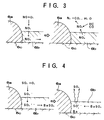
- NOx absorption and release mechanisms of the NOx absorbent 6 are illustrated in FIG. 3. More particularly, in an excess oxygen exhaust gas condition, NO and O2 react with each other at a surface of Pt to form NO2, which is diffused into the Ba layer (more exactly, the layer of Ba(OH)2, BaO) in the form of NO3 ⁇ so that NOx is absorbed by the Ba layer. In this instance, since NO has been oxidized to the form of NO2, the NOx can easily react with Ba to be easily absorbed by the Ba layer. When the oxygen concentration of the exhaust gas decreases, the NO3 ⁇ which has been absorbed in the Ba layer is released from the Ba layer and is changed to the form of NO2. The NO2 is then reduced to N2 by the reducing materials such as HC and CO contained in the exhaust gas at the surface of Pt.
- the reducing materials such as HC and CO contained in the exhaust gas at the surface of Pt.
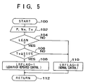
- SOx-poisoning and recovery mechanisms of the NOx absorbent are illustrated in FIG. 4.
- SOx in the exhaust gas for example, SO2
- SO4 2 ⁇ on the surface of Pt
- the sulfate ion is diffused into the Ba layer to form sulfate (for example, BaSO4).
- the sulfate grows unlikely to be decomposed with the lapse of time, the sulfate should be decomposed within a relatively short time period by decreasing the oxygen concentration of the exhaust gas, for example, by changing the air-fuel ratio to a rich air-fuel ratio.
- the oxygen concentration of the exhaust gas decreases, as illustrated in the right half portion of FIG.
- the sulfate is decomposed to a sulfate ion in the vicinity of Pt, which is in turn reduced to SO2.
- the SO2 is gas and is easily released from the Ba layer.
- exhaust gas sensors 10 and 10A are disposed in the exhaust conduit 4 upstream and downstream of the NOx absorbent 6, respectively, for the purpose of detecting the current exhaust gas temperature Te and the current NOx absorbent temperature.
- an engine load sensor for example, an intake pressure sensor
- an engine speed sensor 14 are provided for the purpose of detecting the current engine operating condition.
- the engine speed Ne may be calculated from the output of a crank angle sensor housed in a distributor.
- the ECU 8 may be constituted of a micro computer. As with a conventional micro computer, the ECU 8 preferably includes input and output interfaces, a read-only memory (ROM), a random access memory (RAM) for storing data temporally, and a central processor unit (CPU) for conducting calculation. The ECU may further include an analog/digital convertor which converts analog signals to digital signals when the fed signals are analog ones. Instruction signals which are the results of calculation at the CPU are sent from the output interface to an exhaust gas oxygen concentration control means 16 to control the oxygen concentration of the exhaust gas.
- the exhaust gas oxygen concentration control means 16 includes, for example, an electronic control fuel injection valve which can control the air-fuel ratio by controlling an injection amount of fuel.
- the oxygen concentration of exhaust gas is 0.3-0.5% at the stoichiometric air-fuel ratio, about 4% at the air-fuel ratio of 18, and 7-7.5% at the air-fuel ratios of 22-23.
- lean burn engines can be operated at air-fuel ratios above 22.
- FIGS. 5-8 illustrate the first embodiment of the invention wherein an oxygen concentration of exhaust gas is decreased repeatedly when the exhaust gas is in a condition of excess oxygen and high temperature.
- Control routines as shown in FIGS. 5, 6 and 7 are provided for recovering an SOx-poisoned NOx absorbent 6.
- the control routines are stored in the ROM and called by the CPU where calculations are conducted in the order of calculations of FIGS. 5, 6, and 7.
- the routine of FIG. 5 constitutes an operating condition determining means of the first embodiment of the invention for determining whether or not the current exhaust gas condition is in a condition of excess oxygen and high temperature
- the routine of FIG. 7 constitutes an exhaust gas oxygen concentration control means of the first embodiment of the invention for decreasing the oxygen concentration of exhaust gas when the current exhaust gas condition is in a condition of excess oxygen and the exhaust gas or NOx absorbent temperature is high.
- This control means includes means for repeatedly producing a rich air fuel-ratio for controlling fuel injection so that the air-fuel ratio is repeatedly changed to a rich ratio.
- the control routine of FIG. 5 is entered at predetermined time intervals.
- the routine of FIG. 5 is entered at step 100.
- the current engine operating conditions including an engine load P, an engine speed Ne, and an exhaust gas temperature Te are entered.
- An output of the exhaust gas temperature sensor 10 is used for the exhaust gas temperature.
- the exhaust gas temperature may be presumed from a map which stores the relationship between Te and P, Ne obtained tests.
- a fuel injection amount is determined based on P and Ne, and thus the air-fuel ratio has been determined before the routine proceeds to step 102.
- a predetermined temperature for example, 550°C in exhaust gas temperature and 500°C in NOx absorbent temperature.
- the current condition is deemed to be a condition in which the air-fuel ratio is controlled so that it repeatedly becomes rich and then lean thereby recovering the SOx-poisoned NOx absorbent, and the routine proceeds to step 108 where the lean and rich repeated control flag LRFLAG is set to "1". Then, the routine proceeds to step 112 where the cycle ends.
- the current operating condition is deemed to be a condition in which no recovery control of the NOx absorbent is to be conducted, and the routine proceeds to step 110 where flag LRFLAG is cleared to "0". Then, the routine proceeds to step 112 and the cycle ends.
- the routine of FIG. 6 is a routine for conducting a flag control for the lean and rich air-fuel ratio repeated control.
- the routine is entered at step 120.
- a decision is made as to whether or not the lean and rich repeated control flag LRFLAG is set at "1". If LRFLAG is not at "1", the current condition is not in a condition where the lean and rich repeated control for recovery of the NOx absorbent is to be conducted, and therefore the routine proceeds to step 138 and returns.
- step 124 a flag control is conducted so that the engine is operated at lean air-fuel ratios for a first predetermined time period and then at rich air-fuel ratios for a second predetermined time period and the lean and rich operations are repeated. More particularly, at step 124, a decision is made as to whether or not lean flag is set at "1" (this means, rich flag is set at "0"). If lean flag is set at "1", the routine proceeds to step 126 where the lean operation time period is counted by, for example, adding a time interval of entering the routine (delta t) to the counted lean operation period (SLP) of the previous cycle.
- SLP accumulated lean operation period
- step 132 the rich operation time period (SRP) is counted by, for example, adding the interval (delta t) to the counted rich operation period of the previous cycle. Then, at step 134, a decision is made as to whether or not the accumulated rich operation period (SRP) exceeds a second predetermined time period (for example, 3 seconds). If SRP does not exceeds the second period, the rich operation should be maintained, and therefore the routine proceeds to step 138 where the cycle ends.
- SRP rich operation time period
- step 136 lean flag is set to "1" (this means that rich flag is set to "0"), and then the routine proceeds to step 138 and returns.
- rich flag is set at "1" (lean flag is set at "0") for the second period.
- step 142 a decision is made as to whether or not the lean and rich repeated control flag LRFLAG is set at "1", that is, whether or not the current condition is in a condition where the recovering control of the SOx-poisoned NOx absorbent should be conducted. If flag LRFLAG is set at "1" at step 142, the routine proceeds to step 144 where a decision is made as to whether or not rich flag is set at "1" (this means that lean flag is set at "0"). If rich flag is "1", the routine proceeds to step 146 where a rich air-fuel ratio operation is conducted, and then proceeds to step 150 where the cycle ends.
- the rich air-fuel ratio control at step 146 is executed by setting a rich control flag RCON (see FIG. 8) at "1". If LRFLAG is not “1" and if rich flag is not “1", the routine proceeds to step 148, where flag RCON is set at "0" and then proceeds to step 150 where the cycle ends.
- step 174 the fuel injection control is normal and therefore the routine proceeds to step 174, where TAU is set and fuel injection is conducted for the period of TAU. Then, the routine proceeds to step 176 where the cycle ends. If flag RCON is "1" at step 170, the routine proceeds to step 172 where TAU is changed to TAUR (a fuel injection period for making the air-fuel ratio rich) despite the calculation at step 168. Then, the routine proceeds to step 174, where TAU of TAUR is set. Then, the routine proceeds to step 176 where the cycle ends. In this way, the rich air-fuel control of step 146 of FIG. 7 is conducted.
- NOx included in exhaust gas is absorbed by the NOx absorbent 6, so that the amount of NOx exhausted to the atmosphere is suppressed.
- the NOx absorption ability of the NOx absorbent 6 may gradually decrease due to SOx-poisoning when it is used for a long time period.
- the exhaust gas condition of excess oxygen and high temperature for example, higher than 550°C is detected.
- the lean and rich air-fuel ratio repeated control is executed wherein a lean air-fuel ratio operation is conducted for a first period (for example, two minutes) and then a rich air-fuel ratio operation is conducted for a second period (for example, three seconds).
- a lean air-fuel ratio operation is conducted for a first period (for example, two minutes) and then a rich air-fuel ratio operation is conducted for a second period (for example, three seconds).
- the NOx absorbent is recovered according to the mechanism shown in the right half portion of FIG. 4.
- the reason why the rich air-fuel ratio operation is introduced before a relatively long period has elapsed is to recover the NOx absorbent before the SOx-poisoning proceeds to the interior of the NOx absorbent, that is, while only the surface portion of the NOx absorbent is SOx-poisoned, so that recovery is easy. If sulfate ions diffuse to the interior of the absorbent to form sulfate and the state is maintained for a long period of time, recovery of the NOx absorbent from the SOx-degradation is difficult.
- FIG. 9 illustrates the second embodiment of the invention wherein the oxygen concentration of exhaust gas is maintained at a decreased state continuously for a certain period of time when it is detected that the exhaust gas is in an excess oxygen condition and the exhaust gas or NOx absorbent temperature is high (higher than 550°C in exhaust gas temperature and 550°C in NOx absorbent temperature).
- the exhaust gas or NOx absorbent temperature is high (higher than 550°C in exhaust gas temperature and 550°C in NOx absorbent temperature).
- the routine of FIG. 9 is entered at step 200.
- the current engine operating conditions including an engine speed and an engine load are entered.
- a current objective air-fuel ratio is determined based on the entered engine operating conditions.
- the routine proceeds from step 204 to step 212 where fuel injection is conducted.
- steps 206, 208 and 210 are added. More particularly, the routine proceeds from step 204 to step 206 where the current NOx absorbent temperature (or exhaust gas temperature) is entered. Then, at step 208, a decision is made as to whether the oxygen concentration of the exhaust gas is high and the NOx absorbent temperature is high (for example, higher than 500°C).
- Step 208 constitutes an operating condition determining means of the second embodiment of the invention. If the exhaust gas is in an excess oxygen condition and the NOx absorbent temperature is high, the routine proceeds to step 210 where the objective air-fuel ratio is changed from the ratio determined at step 204 to a stoichiometric air-fuel ratio. By this procedure, the oxygen concentration of exhaust gas is decreased continuously for a certain time period so that the NOx absorbent is unlikely to be SOx-poisoned. Step 210 constitutes an exhaust gas oxygen concentration continuously decreasing means of the second embodiment of the invention.
- FIG. 10 illustrates the third embodiment of the invention.
- Steps 302 and 304 constitutes a fuel-cutting ceasing means of the third embodiment of the invention.
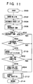
- FIG. 11 illustrates the fourth embodiment of the invention. It has been found in tests for developing the invention that the NOx absorbent is SOx-poisoned only in a certain high temperature range, more particularly, in an exhaust gas temperature range of about 550°C-750°C (in an NOx absorbent temperature range of about 500°C-700°C). Degradation of the NOx absorbent due to SOx is not promoted at NOx absorbent temperatures higher than 700°C.
- the exhaust gas oxygen concentration control means decreases the oxygen concentration only when it is found that the current exhaust gas temperature (or NOx absorbent temperature) is within the above-described temperature range so that the fuel economy of the engine is improved.
- steps 402 and 404 are added to the control routine of the third embodiment of the invention (the routine of FIG. 10).
- steps 402 and 404 a decision is made as to whether or not the current exhaust gas temperature is within the range of 500°C-700°C (or the NOx absorbent temperature is within the range of 550°C-750°C). Only when the temperature is within the range, the routine proceeds to step 210 where the oxygen concentration is decreased.
- steps 402 and 404 constitute an operating condition determining means of the fourth embodiment of the invention.
- Other structures and operation of the fourth embodiment of the invention are the same as those of the third embodiment of the invention.
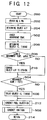
- FIG. 12 illustrates the fifth embodiment of the invention.
- degradation of the NOx absorbent due to SOx in an excess oxygen gas condition is promoted only when the exhaust gas or NOx absorbent temperature is within a certain temperature range.
- the NOx absorbent temperature is increased to a temperature above that temperature range so that SOx-poisoning of the NOx absorbent is not promoted.
- the ignition timing of the engine is delayed so that the exhaust gas or NOx absorbent temperature is increased to a temperature above the temperature range.
- step 204 the routine proceeds from step 204 to step 502 where the current objective ignition timing is determined based on the current engine operating condition. From steps 208 and 210, the routine proceeds to 504 where it is determined whether or not the NOx absorbent temperature is lower than 700°C. If the NOx absorbent temperature is not lower than 700°C, the routine proceeds to step 212. If the NOx absorbent temperature is lower than 700°C, the routine proceeds to step 506 where the objective ignition timing is delayed and then the routine proceeds to step 212. From step 212, the routine proceeds to step 508 where ignition in accordance with the objective ignition timing is conducted. Then, the routine proceeds to step 214.
- steps 208 and 504 constitute an operating condition determining means of the fifth embodiment of the invention which determines whether or not the current NOx absorbent or exhaust gas temperature is high and within the predetermined temperature range.
- steps 210, 506 and 508 constitute an exhaust gas oxygen concentration control means of the fifth embodiment of the invention which increases the NOx absorbent temperature to a temperature above the predetermined temperature range when it is found that the NOx absorbent temperature is in the temperature range.
- FIG. 13 illustrates the sixth embodiment of the invention.
- the sixth embodiment of the invention aims to presume the exhaust gas or NOx absorbent temperature based on a vehicle speed without installing a temperature sensor. Therefore, an operating condition detecting means of the sixth embodiment includes a vehicle speed sensor 18 (see FIGS. 1 and 2). In this instance, the higher the vehicle speed, the higher the exhaust gas or NOx absorbent temperature is.
- the vehicle speed corresponding to the exhaust gas temperature 550°C is about 100 Km/h.
- step 602 the routine proceeds to from step 204 to step 602 where a decision is made as to whether or not the current vehicle speed exceeds the predetermined vehicle speed (for example, 100 Km/h). If the current vehicle speed exceeds the predetermined vehicle speed, the exhaust gas temperature is presumed to be high, and the routine proceeds to step 210. At step 210, the objective air-fuel ratio is changed to a stoichiometric air-fuel ratio, and then the routine proceeds to step 212. If the predetermined vehicle speed does not exceed the predetermined vehicle speed at step 602, the routine proceeds directly to step 212.
- Step 602 constitutes an operating condition determining means of the sixth embodiment of the invention. Other structures and operation of the sixth embodiment of the invention are the same as those of the second embodiment of the invention.
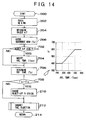
- FIG. 14 illustrates the seventh embodiment of the invention.
- the NOx absorbent temperature continues to be low and does not reach the switching temperature (550°C in exhaust gas temperature and 500°C in NOx absorbent temperature) at which the air-fuel ratio is to be switched from the lean air-ratio to a rich air-ratio.
- the switching temperature 550°C in exhaust gas temperature and 500°C in NOx absorbent temperature
- SOx-poisoning of the NOx absorbent will be gradually promoted.
- the NOx absorbent is poisoned though the poisoning is very slow.
- the sulfur component (SO2) will be released from the NOx absorbent if the SOx-poisoned NOx absorbent is heated at a temperature a little higher than the temperature at which the NOx absorbent has been SOx-poisoned, and the NOx absorbent will be recovered.
- the reference temperature for determining whether or not the air-fuel ratio is to be switched to a rich air-fuel ratio can be set at a low temperature.
- the NOx absorbent temperature should be increased to a temperature (for example, 600°C) higher than the high temperature to recover the NOx absorbent, and thus the reference temperature for determining whether the air-fuel ratio is to be switched to a rich ratio should be set at a high temperature.
- the reference temperature for determining the switching timing is changed in accordance with the history of the temperatures that the NOx absorbent has experienced at lean air-fuel ratio operation.
- step 208 of FIG. 9 is replaced by steps 702-708 in FIG. 14.
- a reference temperature T0 for determining whether the engine operation is to be switched from a lean air-fuel ratio operation to a rich air-fuel ratio operation is obtained in accordance with the average temperature Tave based on a map shown in FIG. 14.
- the relationship between T0 and Tave is predetermined such that in the vicinity of 500°, the higher Tave, the higher T0 is.
- the routine proceeds to step 708 where a decision is made as to whether or not the current NOx absorbent temperature Ta is higher than the reference temperature T0.
- step 212 If Ta is not higher than T0, the routine proceeds to step 212, and if Ta is higher than T0, the condition is deemed to be in a lean air-fuel ratio condition and the routine proceeds to step 210 where the air-fuel ratio is changed from a lean air-fuel ratio to a rich air-fuel ratio so that the oxygen concentration of the exhaust gas is decreased.
- step 210 Other structures and operation of the seventh embodiment of the invention are the same as those of the second embodiment of the invention.
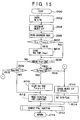
- FIG. 15 illustrates the eighth embodiment of the invention.
- the condition where recovery of the SOx-poisoned NOx absorbent is conducted should be limited to the condition where the exhaust gas includes excess oxygen and where the exhaust gas or NOx absorbent temperature is high, for improving the fuel economy. Since the NOx absorbent has a large heat capacity, when the NOx absorbent temperature rises above 500°C, the NOx absorbent temperature will not immediately decrease in response to a decrease in the exhaust gas temperature though the exhaust gas temperature decreases to a temperature lower than 500°C. As a result, switching from the stoichiometric or rich air-fuel ratio to a lean air-fuel ratio is delayed, and fuel economy decreases.
- a switching temperature from a stoichiometric or rich air-fuel ratio to a lean air-fuel ratio is set lower than a switching temperature from a lean air-fuel ratio to a stoichiometric or rich air-fuel ratio, for example set lower by 50°C than a maximum NOx absorbent temperature, so that the engine operation can easily return to a lean air-fuel ratio operation.
- steps 802-814 are added to the routine of FIG. 9.
- the routine proceeds from step 206 to step 802 and then to 804 so that a maximum NOx absorbent temperature Tmax is stored.
- the routine proceeds to step 806 where a decision is made as to whether the engine is in a rich air-fuel ratio operation referring to rich control flag. If the engine is in a lean air-fuel ratio operation, the routine proceeds to step 208 where a decision is made whether or not the maximum temperature Tmax which the NOx absorbent has experienced exceeds a switching temperature (for example, 500°C).
- a switching temperature for example, 500°C
- step 210 the air-fuel ratio is changed from the lean ratio to a stoichiometric or rich ratio, and then the routine proceeds to step 814.
- step 814 the rich control flag is set and then the routine proceeds to step 212. If Tmax is equal to or lower than 500°C at step 208, it is deemed that the lean air-fuel operation may be continued, and the routine proceeds to step 812.
- step 812 the rich control flag is reset (lean control flag is set), and the routine proceeds to step 212.
- step 806 the routine proceeds from step 806 to 808 so that the stoichiometric or rich air-fuel ratio operation is continued.
- the NOx absorbent temperature Ta decreases. If it is determined at step 808 that Ta has decreased to a temperature lower than the temperature of Tmax-50°C, the routine proceeds from step 808 to step 810 where Tmax is cleared to zero, and the routine proceeds to step 812.
- the rich control flag is reset, and then at step 212 the lean air-fuel ratio operation is continued. If Ta is equal to or higher than the temperature of Tmax-50°C, the stoichiometric or rich air-fuel operation is continued.
- the reference temperature for switching the engine operation from the stoichiometric or rich air-fuel ratio operation to a lean air-fuel ratio operation can be set lower than the reference temperature for switching the engine operation from the lean air-fuel ratio operation to a stoichimetric or rich air-fuel ratio operation, so that the engine operation can be smoothly returned to a lean air-fuel ratio operation.
- Other structures and operation of the eighth embodiment of the invention are the same as those of the second embodiment of the invention.
- FIG. 16 illustrates the ninth embodiment of the invention.
- means (steps 902 and 904) are added to the routine of the eighth embodiment, for returning the rich air-fuel operation to a lean air-fuel ratio operation independently of the NOx absorbent temperature if the rich air-fuel ratio operation continues for a predetermined time period (for example, ten minutes) so that the operation is sure to return to the lean air-fuel ratio operation.
- step 808 determines whether Ta is higher than Tmax-50°C and the rich air-fuel ratio operation is to be continued.
- the routine proceeds to step 902 where the rich air-fuel operation period is counted. Then, the routine proceeds to step 904 where a decision is made as to whether the counted period exceeds a predetermined period, for example 10 minutes. If the counted period exceeds the predetermined period, the routine proceeds to step 810 and then step 812 where the operation is switched to a lean air-fuel ratio operation. If the counted period does not exceed the predetermined period, it is deemed that the rich air-fuel ratio may be continued, and the routine proceeds to step 210.
- Other structures and operation of the ninth embodiment of the invention are the same as those of the eighth embodiment of the invention.
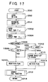
- FIG. 17 illustrates the tenth embodiment of the invention.
- the heat capacity of the NOx absorbent is large, if the oxygen concentration control is conducted based on the NOx absorbent temperature, switching from the rich air-fuel ratio to a lean air-fuel ratio is delayed. This delay will be accompanied by a decrease in fuel economy.
- the NOx absorbent inlet temperature alters largely, if the oxygen concentration control is conducted based on the NOx absorbent inlet temperature, the air-fuel ratio may be switched from the lean air-fuel ratio to a rich air-fuel ratio too early. That is also accompanied by a decrease in fuel economy.
- an operating condition detecting means of the tenth embodiment of the invention includes both the inlet gas temperature 10 and an outlet gas temperature 10A (see FIGS. 1 and 2).
- steps 1002-1014 are added to the routine of the second embodiment (FIG. 9).
- the routine proceeds from step 204 to step 1002 and then to step 1004 where the current inlet gas temperature Tin and outlet gas temperature Tout of the NOx absorbent are entered.
- step 1006 a decision is made referring to the rich control flag as to whether or not the engine is in a stoichiometric or rich air-fuel ratio operation. If the engine is not in a stoichiometric or rich air-fuel ratio operation, the routine proceeds to step 1008 where a decision is made as to whether or not the current NOx absorbent outlet temperature Tout exceeds a predetermined temperature (for example, 500°C).
- a predetermined temperature for example, 500°C
- the routine proceeds to step 210 where the engine operation is changed to a stoichiometric operation. Then, the routine proceeds to step 1014 where the rich control flag is set. Then, the routine proceeds to step 212. If Tout is equal to or lower than 500°C at step 1008, it is deemed that the lean air-fuel operation may be continued, and the routine proceeds to step 1010 where the rich control flag is reset. Then, the routine proceeds to step 212. If the engine is in a rich air-fuel operation at step 1006, the routine proceeds to step 1012 where a decision is made as to whether the NOx absorbent inlet temperature Tin exceeds a predetermined temperature (for example, 400°C).
- a predetermined temperature for example, 400°C
- Tin is lower than the predetermined temperature, it is deemed that the lean air-fuel ratio operation may be continued, and the routine proceeds to step 1010. If Tin is higher than the predetermined temperature at step 1012, the routine proceeds to step 210 and the stoichiometric or rich air-fuel operation is continued.
- Other structures and operation of the tenth embodiment of the invention are the same as those of the second embodiment of the invention.
- the oxygen concentration of exhaust gas is decreased when the exhaust gas is in an excess oxygen condition and the exhaust gas or NOx absorbent temperature is high, the sulfate absorbed in the NOx absorbent is reduced to SO2 which is easily released from the NOx absorbent so that the SOx-poisoned NOx absorbent is recovered and the durability of the exhaust gas purification apparatus is improved.
Abstract
Description
- The present invention relates to an exhaust gas purification apparatus for an internal combustion engine installing an NOx (nitrogen oxides) absorbent in an exhaust conduit of the engine, and particularly relates to an exhaust gas purification apparatus capable of recovering an NOx absorbent poisoned by sulfur oxides (SOx).
- Internal combustion engines capable of fuel combustion at lean air-fuel ratios (lean burn engines) have been noted as engines which can both improve fuel economy and suppress the exhaust of CO₂. However, since a conventional catalyst (three-way catalyst) cannot purify NOx in exhaust gas from an engine operated at lean air-fuel ratios (that is, in exhaust gas including excess oxygen), catalysts or systems that can suppress the exhaust of NOx into the atmosphere even at lean air-fuel ratios are desired.
- For example, Japanese Patent Application HEI 4-73264 filed February 25th, 1992 proposes an exhaust gas purification apparatus wherein an NOx absorbent including lanthanum (La), which is one kind of rare-earth, and platinum (Pt) is installed in an engine exhaust conduit. In the apparatus, NOx is absorbed by the La during an engine operation at lean air-fuel ratios, and the NOx absorbed by the La is released from the La at an engine operation at a stoichiometric or rich air-fuel ratio and is decomposed (or reduced) into N₂.
- However, it has been found in tests executed for developing the present invention that if a high temperature and excess oxygen exhaust gas condition continues for a relatively long time period, the NOx absorption rate of the NOx absorbent decreases.
- One reason for such degradation of the NOx absorbent is presumed to be that SOx (for example, SO₂ which is produced from sulfur contained in fuel) is oxidized to sulfate ion (
SO₄ ²⁻), which is diffused into and is absorbed by the NOx absorbent to form an obstinate sulfate which obstructs the absorption of NOx by the NOx absorbent. - An object of the invention is to provide an exhaust gas purification apparatus for an internal combustion engine installing an NOx absorbent in an engine exhaust conduit wherein the NOx absorbent poisoned by SOx is recovered to a nearly original non-poisoned state by controlling an operation of the engine.
- The above-described object is achieved by an exhaust gas purification apparatus for an internal combustion engine in accordance with the present invention. The present invention is directed to an internal combustion engine capable of fuel combustion at lean air-fuel ratios and an exhaust conduit connected to the engine, an NOx absorbent installed in the exhaust conduit, including at least one kind of element selected from the group consisting of alkaline earth, rare-earth, and alkaline metals or an oxide of the element, wherein the NOx absorbent absorbs NOx in exhaust gas including excess oxygen and releases the NOx which the NOx absorbent has absorbed when an oxygen concentration of the exhaust gas decreases. The apparatus further includes operating condition detecting means for detecting an operating condition of the engine, operating condition determining means for determining whether the exhaust gas from the engine is in a condition wherein the exhaust gas includes excess oxygen and wherein the exhaust gas or NOx absorbent temperature is high, and exhaust gas oxygen concentration control means for decreasing the oxygen concentration of the exhaust gas flowing to the NOx absorbent when the operating condition determining means determines that the exhaust gas is in a condition wherein the exhaust gas includes excess oxygen and wherein the exhaust gas or NOx absorbent temperature is high.
- In tests conducted conducted for developing the invention, the following facts were found: When the exhaust gas included excess oxygen (exhaust gas from the engine operated at lean air-fuel ratios) and when the exhaust gas or NOx absorbent temperatures were high (for example, higher than 550°C in exhaust gas temperature), sulfate (for example, BaSO₄) was formed in the NOx absorbent carrying barium (Ba, one kind of alkaline earth) and the NOx absorbent was poisoned by SOx (SOx-poisoned). When the SOx-poisoned NOx absorbent was burnt in air at about 1100°C, the sulfate was decomposed to SO₂, and the SO₂ in the form of gas was released from the NOx absorbent, so that the NOx absorbent was recovered nearly to an original, non-poisoned state. When the SOx-poisoned catalyst was burnt in decompressed air, the sulfate was decomposed and the NOx absorbent was recovered even at about 900°C. Further, in a reducing gas condition (which corresponds to exhaust gas containing no oxygen but reducing materials such as hydrocarbons, and corresponds to, for example, exhaust gas from an engine operated at lean-air fuel ratios), the sulfate was decomposed and the NOx absorbent was recovered even at about 550°C in exhaust gas temperature.
- The above-found facts are used in the apparatus of the invention for recovering the NOx absorbent installed in the engine exhaust conduit from the SOx-poisoning thereof. More particularly, when the operating condition determining means determines that the engine exhaust gas is in a condition of excess oxygen and the engine exhaust or NOx absorbent temperature is high, the oxygen concentration control means decreases the oxygen concentration of the exhaust gas repeatedly or continuously. When the oxygen concentration decreases, the sulfate formed in the NOx absorbent is decomposed and is released from the NOx absorbent so that the NOx absorbent is recovered.
- The above-described object and other objects, features, and advantages of the present invention will become more apparent and will be more readily appreciated from the following detailed description of the preferred embodiments of the invention taken in conjunction with the accompanying drawings, in which:
- FIG. 1 is a schematic diagram of an exhaust gas purification apparatus for an internal combustion engine including an NOx absorbent, which is applicable to all embodiments of the invention;
- FIG. 2 is a schematic diagram of an exhaust gas purification apparatus wherein an NOx absorbent system includes a combination of an NOx absorbent and a conventional three-way catalyst, which is applicable to all the embodiments of the invention;
- FIG. 3 is a diagram illustrating NOx absorption and release mechanisms of the NOx absorbent, which is applicable to all the embodiments of the invention;
- FIG. 4 is a diagram illustrating mechanisms of SOx-poisoning and recovery therefrom of the NOx absorbent, which is applicable to all the embodiments of the invention;
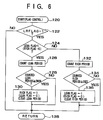
- FIG. 5 is a flow chart of a control routine of an operating condition determining means in accordance with a first embodiment of the invention;
- FIG. 6 is a flow chart of a flag control for repetition of lean and rich air-fuel ratio operations in accordance with the first embodiment of the invention;
- FIG. 7 is a flow chart of a control routine of a rich air-fuel ratio condition repeatedly producing means in accordance with the first embodiment of the invention;
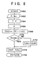
- FIG. 8 is a flow chart of a schematic fuel injection control routine in accordance with the first embodiment of the invention;
- FIG. 9 is a control flow chart of an exhaust gas purification apparatus in accordance with a second embodiment of the invention;
- FIG. 10 is a control flow chart of an exhaust gas purification apparatus in accordance with a third embodiment of the invention;
- FIG. 11 is a control flow chart of an exhaust gas purification apparatus in accordance with a fourth embodiment of the invention;
- FIG. 12 is a control flow chart of an exhaust gas purification apparatus in accordance with a fifth embodiment of the invention;
- FIG. 13 is a control flow chart of an exhaust gas purification apparatus in accordance with a sixth embodiment of the invention;
- FIG. 14 is a control flow chart of an exhaust gas purification apparatus in accordance with a seventh embodiment of the invention;
- FIG. 15 is a control flow chart of an exhaust gas purification apparatus in accordance with an eighth embodiment of the invention;
- FIG. 16 is a control flow chart of an exhaust gas purification apparatus in accordance with a ninth embodiment of the invention; and
- FIG. 17 is a control flow chart of an exhaust gas purification apparatus in accordance with a tenth embodiment of the invention.
- Preferred embodiments of the invention will be explained below with reference to drawings.
- Firstly, structures common to all embodiments of the invention will be explained with reference to FIGS. 1-4. As illustrated in FIG. 1, in an
exhaust conduit 4 connected to aninternal combustion engine 2 capable of fuel combustion at lean air-fuel ratios, an NOx absorbent 6 is installed which absorbs nitrogen oxides (NOx) in exhaust gas including excess oxygen and releases the NOx which the absorbent has absorbed when an oxygen concentration of the exhaust gas decreases. - The NOx absorbent 6 includes a
carrier 6c of, for example, alumina (Al₂O₃) and at least oneelement 6b selected from the group consisting of (a)noble metal catalyst 6a having oxidizing and reducing abilities, for example platinum (Pt) and a mixture of platinum and rhodium (Rh), (b) alkaline earth, for example barium (Ba), (c) rare-earth, for example lanthanum (La), and (d) alkaline metal, for example kalium (K), or an oxide of the element, each carried by thecarrier 6c. The above-describedelement 6b carried by thecarrier 6c may be replaced by a transition metal, for example copper (Cu). - The NOx absorbent 6 of FIG. 1 may be replaced, as illustrated in FIG. 2, by a combination of an NOx absorbent 6A having a weak catalytic ability and a conventional, three-
way catalyst 6B disposed downstream of the NOx absorbent 6A. The NOx absorbent 6A may be constructed of, for example, a double oxide of (a) transition metal (for example, Cu) and (b) alkaline earth, rare-earth, or alkaline metal each having an NOx absorbing ability. Such absorbent 6A includes, for example, a Ba-Cu-O base absorbent. - NOx absorption and release mechanisms of the NOx absorbent 6 are illustrated in FIG. 3. More particularly, in an excess oxygen exhaust gas condition, NO and O₂ react with each other at a surface of Pt to form NO₂, which is diffused into the Ba layer (more exactly, the layer of Ba(OH)₂, BaO) in the form of NO₃⁻ so that NOx is absorbed by the Ba layer. In this instance, since NO has been oxidized to the form of NO₂, the NOx can easily react with Ba to be easily absorbed by the Ba layer. When the oxygen concentration of the exhaust gas decreases, the NO₃⁻ which has been absorbed in the Ba layer is released from the Ba layer and is changed to the form of NO₂. The NO₂ is then reduced to N₂ by the reducing materials such as HC and CO contained in the exhaust gas at the surface of Pt.
- SOx-poisoning and recovery mechanisms of the NOx absorbent are illustrated in FIG. 4. As illustrated in the left half portion of FIG. 4, SOx in the exhaust gas (for example, SO₂) is oxidized to SO₃⁻ and then to
SO₄ ²⁻ on the surface of Pt and the sulfate ion is diffused into the Ba layer to form sulfate (for example, BaSO₄). Since the sulfate grows unlikely to be decomposed with the lapse of time, the sulfate should be decomposed within a relatively short time period by decreasing the oxygen concentration of the exhaust gas, for example, by changing the air-fuel ratio to a rich air-fuel ratio. When the oxygen concentration of the exhaust gas decreases, as illustrated in the right half portion of FIG. 4, the sulfate is decomposed to a sulfate ion in the vicinity of Pt, which is in turn reduced to SO₂. The SO₂ is gas and is easily released from the Ba layer. By producing the oxygen concentration decreased condition repeatedly or continuously within a relatively short period of time, SOx-poisoning of the NOx absorbent 6 can be suppressed. For example, in a case of repeatedly producing the oxygen concentration decreased condition, an operation mode wherein the engine is operated at lean air-fuel ratios for about two minutes and then operated at rich air-fuel ratios for about one half (1/2) to three (3) seconds is repeated. In this instance, when the exhaust gas or NOx absorbent temperature is high, the time period wherein the rich air-fuel ratio is maintained can be shortened. - For conducting the recovery control from the SOx-poisoning of the NOx absorbent, various sensors and devices are provided. More particularly,
exhaust gas sensors exhaust conduit 4 upstream and downstream of the NOx absorbent 6, respectively, for the purpose of detecting the current exhaust gas temperature Te and the current NOx absorbent temperature. For the purpose of detecting the current engine operating condition, an engine load sensor (for example, an intake pressure sensor) 12 and anengine speed sensor 14 are provided. The engine speed Ne may be calculated from the output of a crank angle sensor housed in a distributor. Thesesensors sensors - The ECU 8 may be constituted of a micro computer. As with a conventional micro computer, the
ECU 8 preferably includes input and output interfaces, a read-only memory (ROM), a random access memory (RAM) for storing data temporally, and a central processor unit (CPU) for conducting calculation. The ECU may further include an analog/digital convertor which converts analog signals to digital signals when the fed signals are analog ones. Instruction signals which are the results of calculation at the CPU are sent from the output interface to an exhaust gas oxygen concentration control means 16 to control the oxygen concentration of the exhaust gas. The exhaust gas oxygen concentration control means 16 includes, for example, an electronic control fuel injection valve which can control the air-fuel ratio by controlling an injection amount of fuel. For reference, the oxygen concentration of exhaust gas is 0.3-0.5% at the stoichiometric air-fuel ratio, about 4% at the air-fuel ratio of 18, and 7-7.5% at the air-fuel ratios of 22-23. Usually, lean burn engines can be operated at air-fuel ratios above 22. - Structures and operation specific to each embodiment will now be explained.
- FIGS. 5-8 illustrate the first embodiment of the invention wherein an oxygen concentration of exhaust gas is decreased repeatedly when the exhaust gas is in a condition of excess oxygen and high temperature.
- Control routines as shown in FIGS. 5, 6 and 7 are provided for recovering an SOx-poisoned
NOx absorbent 6. The control routines are stored in the ROM and called by the CPU where calculations are conducted in the order of calculations of FIGS. 5, 6, and 7. The routine of FIG. 5 constitutes an operating condition determining means of the first embodiment of the invention for determining whether or not the current exhaust gas condition is in a condition of excess oxygen and high temperature, and the routine of FIG. 7 constitutes an exhaust gas oxygen concentration control means of the first embodiment of the invention for decreasing the oxygen concentration of exhaust gas when the current exhaust gas condition is in a condition of excess oxygen and the exhaust gas or NOx absorbent temperature is high. This control means includes means for repeatedly producing a rich air fuel-ratio for controlling fuel injection so that the air-fuel ratio is repeatedly changed to a rich ratio. - The control routine of FIG. 5 is entered at predetermined time intervals. The routine of FIG. 5 is entered at
step 100. Then, atstep 102, the current engine operating conditions including an engine load P, an engine speed Ne, and an exhaust gas temperature Te are entered. An output of the exhaustgas temperature sensor 10 is used for the exhaust gas temperature. The exhaust gas temperature may be presumed from a map which stores the relationship between Te and P, Ne obtained tests. In a conventional fuel injection control, a fuel injection amount is determined based on P and Ne, and thus the air-fuel ratio has been determined before the routine proceeds to step 102. - Then, at
step 104, a decision is made as to whether or not the current air-fuel ratio is lean (that is, greater than 14.7 in air-fuel ratio). If the air-fuel ratio is lean, the routine proceeds to step 106, where a decision is made as to whether or not the current exhaust gas temperature Te (or NOx exhaust gas temperature) is equal to or higher than a predetermined temperature (for example, 550°C in exhaust gas temperature and 500°C in NOx absorbent temperature). When the exhaust gas temperature is high, the current condition is deemed to be a condition in which the air-fuel ratio is controlled so that it repeatedly becomes rich and then lean thereby recovering the SOx-poisoned NOx absorbent, and the routine proceeds to step 108 where the lean and rich repeated control flag LRFLAG is set to "1". Then, the routine proceeds to step 112 where the cycle ends. When the exhaust gas is not in a condition of a lean air-fuel ratio and high temperature, the current operating condition is deemed to be a condition in which no recovery control of the NOx absorbent is to be conducted, and the routine proceeds to step 110 where flag LRFLAG is cleared to "0". Then, the routine proceeds to step 112 and the cycle ends. - The routine of FIG. 6 is a routine for conducting a flag control for the lean and rich air-fuel ratio repeated control. The routine is entered at
step 120. Then, atstep 122, a decision is made as to whether or not the lean and rich repeated control flag LRFLAG is set at "1". If LRFLAG is not at "1", the current condition is not in a condition where the lean and rich repeated control for recovery of the NOx absorbent is to be conducted, and therefore the routine proceeds to step 138 and returns. - If LRFLAG is set at "1" at
step 122, the routine proceeds to step 124. Then, a flag control is conducted so that the engine is operated at lean air-fuel ratios for a first predetermined time period and then at rich air-fuel ratios for a second predetermined time period and the lean and rich operations are repeated. More particularly, atstep 124, a decision is made as to whether or not lean flag is set at "1" (this means, rich flag is set at "0"). If lean flag is set at "1", the routine proceeds to step 126 where the lean operation time period is counted by, for example, adding a time interval of entering the routine (delta t) to the counted lean operation period (SLP) of the previous cycle. Then, atstep 128, a decision is made as to whether or not the accumulated lean operation period (SLP) exceeds a first predetermined period (for example, two minutes). If SLP does not exceed the first period, the current engine operating condition is a condition where the lean operation is to be maintained, and the routine proceeds to step 138 where the cycle ends. If SLP exceeds the first period, the routine proceeds to step 130 where rich flag is set to "1" (this means that lean flag is set to "0"), and then the routine proceeds to step 138 and returns. By this procedure, lean flag is set at "1" (rich flag is set at "1") for the first period. - If lean flag is not set at "1" (rich flag is not set at "0"), the routine proceeds to step 132 where the rich operation time period (SRP) is counted by, for example, adding the interval (delta t) to the counted rich operation period of the previous cycle. Then, at
step 134, a decision is made as to whether or not the accumulated rich operation period (SRP) exceeds a second predetermined time period (for example, 3 seconds). If SRP does not exceeds the second period, the rich operation should be maintained, and therefore the routine proceeds to step 138 where the cycle ends. If SRP exceeds the second period, the routine proceeds to step 136, where lean flag is set to "1" (this means that rich flag is set to "0"), and then the routine proceeds to step 138 and returns. By this procedure, rich flag is set at "1" (lean flag is set at "0") for the second period. - Then, the routine of FIG. 7 is entered at
step 140. Then, atstep 142, a decision is made as to whether or not the lean and rich repeated control flag LRFLAG is set at "1", that is, whether or not the current condition is in a condition where the recovering control of the SOx-poisoned NOx absorbent should be conducted. If flag LRFLAG is set at "1" atstep 142, the routine proceeds to step 144 where a decision is made as to whether or not rich flag is set at "1" (this means that lean flag is set at "0"). If rich flag is "1", the routine proceeds to step 146 where a rich air-fuel ratio operation is conducted, and then proceeds to step 150 where the cycle ends. The rich air-fuel ratio control atstep 146 is executed by setting a rich control flag RCON (see FIG. 8) at "1". If LRFLAG is not "1" and if rich flag is not "1", the routine proceeds to step 148, where flag RCON is set at "0" and then proceeds to step 150 where the cycle ends. - FIG. 8 illustrates a fuel injection control routine which is entered after the routine of FIG. 7, which includes added
steps step 160. Then, at step 162, the current engine load P and the current engine speed Ne are entered. Then, atstep 164, a basic fuel injection amount TP is determined based on the entered P and Ne. Atstep 166, various modification factors are determined. Then, atstep 168, fuel injection time period TAU is determined from the following equation:
Then, the routine proceeds to step 170 where a decision is made as to whether flag RCON determined atsteps step 170, the routine proceeds to step 172 where TAU is changed to TAUR (a fuel injection period for making the air-fuel ratio rich) despite the calculation atstep 168. Then, the routine proceeds to step 174, where TAU of TAUR is set. Then, the routine proceeds to step 176 where the cycle ends. In this way, the rich air-fuel control ofstep 146 of FIG. 7 is conducted. - Operation of the first embodiment of the invention will now be explained. NOx included in exhaust gas is absorbed by the
NOx absorbent 6, so that the amount of NOx exhausted to the atmosphere is suppressed. However, the NOx absorption ability of theNOx absorbent 6 may gradually decrease due to SOx-poisoning when it is used for a long time period. For the purpose of recovering the SOx-poisoned NOx absorbent, the exhaust gas condition of excess oxygen and high temperature (for example, higher than 550°C) is detected. - In such an exhaust gas condition, recovery of the
NOx absorbent 6 is possible. So, the lean and rich air-fuel ratio repeated control is executed wherein a lean air-fuel ratio operation is conducted for a first period (for example, two minutes) and then a rich air-fuel ratio operation is conducted for a second period (for example, three seconds). In the rich air-fuel ratio operation, the NOx absorbent is recovered according to the mechanism shown in the right half portion of FIG. 4. - The reason why recovery of the NOx absorbent is conducted at temperatures higher than the predetermined temperature (550°C in exhaust gas temperature and 500°C in NOx absorbent temperature) is that absorption of NOx is promoted more than generation of sulfate due to SOx so that the NOx absorbent is little SOx-poisoned at that temperature range.
- The reason why the rich air-fuel ratio operation is introduced before a relatively long period has elapsed is to recover the NOx absorbent before the SOx-poisoning proceeds to the interior of the NOx absorbent, that is, while only the surface portion of the NOx absorbent is SOx-poisoned, so that recovery is easy. If sulfate ions diffuse to the interior of the absorbent to form sulfate and the state is maintained for a long period of time, recovery of the NOx absorbent from the SOx-degradation is difficult.
- FIG. 9 illustrates the second embodiment of the invention wherein the oxygen concentration of exhaust gas is maintained at a decreased state continuously for a certain period of time when it is detected that the exhaust gas is in an excess oxygen condition and the exhaust gas or NOx absorbent temperature is high (higher than 550°C in exhaust gas temperature and 550°C in NOx absorbent temperature). By the decrease in the excess oxygen, the NOx absorbent is unlikely to be SOx-poisoned and is recovered from an SOx-poisoned state even if it is poisoned.
- More particularly, the routine of FIG. 9 is entered at
step 200. Then, atstep 202, the current engine operating conditions including an engine speed and an engine load are entered. Atstep 204, a current objective air-fuel ratio is determined based on the entered engine operating conditions. In a conventional air-fuel ratio control, the routine proceeds fromstep 204 to step 212 where fuel injection is conducted. However, in the second embodiment of the invention, steps 206, 208 and 210 are added. More particularly, the routine proceeds fromstep 204 to step 206 where the current NOx absorbent temperature (or exhaust gas temperature) is entered. Then, atstep 208, a decision is made as to whether the oxygen concentration of the exhaust gas is high and the NOx absorbent temperature is high (for example, higher than 500°C). Step 208 constitutes an operating condition determining means of the second embodiment of the invention. If the exhaust gas is in an excess oxygen condition and the NOx absorbent temperature is high, the routine proceeds to step 210 where the objective air-fuel ratio is changed from the ratio determined atstep 204 to a stoichiometric air-fuel ratio. By this procedure, the oxygen concentration of exhaust gas is decreased continuously for a certain time period so that the NOx absorbent is unlikely to be SOx-poisoned. Step 210 constitutes an exhaust gas oxygen concentration continuously decreasing means of the second embodiment of the invention. - FIG. 10 illustrates the third embodiment of the invention.
- In a conventional air-fuel ratio control, fuel cutting is conducted in a deceleration time so as to improve fuel efficiency. However, if fuel cutting of deceleration is conducted in a high temperature condition higher than 550°C in exhaust gas temperature or higher than 500°C in NOx absorbent temperature, SOx-poisoning of the
NOx absorbent 6 is promoted in the fuel cut, excess oxygen gas condition. For the purpose of preventing the SOx-poisoning, in the third embodiment of the invention, fuel cutting of deceleration is ceased in such a high temperature condition. For ceasing fuel cutting in the high temperature condition, as illustrated in FIG. 10,steps - At
step 302, a decision is made as to whether or not the current engine operating condition is in a condition where fuel cutting is to be conducted, for example whether or not the engine operating condition is in deceleration. If the engine operating condition is not in a condition where fuel cutting is to be conducted, the routine proceeds to step 212, and if the engine operating condition is in a condition where fuel cutting is to be conducted, the routine proceeds to step 304 where the fuel cutting is ceased and fuel cut flag is cleared. Then, the routine proceeds to step 212. By this procedure, in the condition that fuel cutting is to be conducted and the NOx absorbent temperature is high, fuel cutting is ceased so that SOx-poisoning of the NOx absorbent is suppressed. Other structures and operation of the third embodiment of the invention are the same as those of the second embodiment of the invention.Steps - FIG. 11 illustrates the fourth embodiment of the invention. It has been found in tests for developing the invention that the NOx absorbent is SOx-poisoned only in a certain high temperature range, more particularly, in an exhaust gas temperature range of about 550°C-750°C (in an NOx absorbent temperature range of about 500°C-700°C). Degradation of the NOx absorbent due to SOx is not promoted at NOx absorbent temperatures higher than 700°C. Thus, in the fourth embodiment of the invention, the exhaust gas oxygen concentration control means decreases the oxygen concentration only when it is found that the current exhaust gas temperature (or NOx absorbent temperature) is within the above-described temperature range so that the fuel economy of the engine is improved.
- For the purpose of conducting the control, as illustrated in FIG. 11,
steps steps - FIG. 12 illustrates the fifth embodiment of the invention. As discussed above, degradation of the NOx absorbent due to SOx in an excess oxygen gas condition is promoted only when the exhaust gas or NOx absorbent temperature is within a certain temperature range. Thus, when it is found that the NOx absorbent temperature is in the temperature range, the NOx absorbent temperature is increased to a temperature above that temperature range so that SOx-poisoning of the NOx absorbent is not promoted. In the fifth embodiment of the invention, when it is found that the exhaust gas or NOx absorbent temperature is in the temperature range, the ignition timing of the engine is delayed so that the exhaust gas or NOx absorbent temperature is increased to a temperature above the temperature range.
- More particularly, in FIG. 12 which includes
steps step 204 to step 502 where the current objective ignition timing is determined based on the current engine operating condition. Fromsteps step 212, the routine proceeds to step 508 where ignition in accordance with the objective ignition timing is conducted. Then, the routine proceeds to step 214. In this instance, steps 208 and 504 constitute an operating condition determining means of the fifth embodiment of the invention which determines whether or not the current NOx absorbent or exhaust gas temperature is high and within the predetermined temperature range.Steps - FIG. 13 illustrates the sixth embodiment of the invention. In the first through fifth embodiments of the invention, there is a need to provide a temperature sensor to detect the exhaust gas or NOx absorbent temperature, or there is a need to presume the exhaust gas or NOx absorbent temperature based on the engine speed and engine load. Provision of the temperature sensor is accompanied by an increase in cost of the apparatus. The sixth embodiment of the invention aims to presume the exhaust gas or NOx absorbent temperature based on a vehicle speed without installing a temperature sensor. Therefore, an operating condition detecting means of the sixth embodiment includes a vehicle speed sensor 18 (see FIGS. 1 and 2). In this instance, the higher the vehicle speed, the higher the exhaust gas or NOx absorbent temperature is. The vehicle speed corresponding to the exhaust gas temperature 550°C is about 100 Km/h.
- More particularly, in FIG. 13, the routine proceeds to from
step 204 to step 602 where a decision is made as to whether or not the current vehicle speed exceeds the predetermined vehicle speed (for example, 100 Km/h). If the current vehicle speed exceeds the predetermined vehicle speed, the exhaust gas temperature is presumed to be high, and the routine proceeds to step 210. Atstep 210, the objective air-fuel ratio is changed to a stoichiometric air-fuel ratio, and then the routine proceeds to step 212. If the predetermined vehicle speed does not exceed the predetermined vehicle speed atstep 602, the routine proceeds directly to step 212. Step 602 constitutes an operating condition determining means of the sixth embodiment of the invention. Other structures and operation of the sixth embodiment of the invention are the same as those of the second embodiment of the invention. - FIG. 14 illustrates the seventh embodiment of the invention. When a low engine speed and low engine load operation continues for a long time period such as when a vehicle is running on a town street, the NOx absorbent temperature continues to be low and does not reach the switching temperature (550°C in exhaust gas temperature and 500°C in NOx absorbent temperature) at which the air-fuel ratio is to be switched from the lean air-ratio to a rich air-ratio. As a result, SOx-poisoning of the NOx absorbent will be gradually promoted. In this instance, even at low temperatures, the NOx absorbent is poisoned though the poisoning is very slow. It was found in tests conducted in developing the present invention that when the NOx absorbent is poisoned by SOx at certain temperatures in an excess oxygen exhaust gas condition, the sulfur component (SO₂) will be released from the NOx absorbent if the SOx-poisoned NOx absorbent is heated at a temperature a little higher than the temperature at which the NOx absorbent has been SOx-poisoned, and the NOx absorbent will be recovered. In case where the NOx absorbent is poisoned by SOx at relatively low temperatures, the reference temperature for determining whether or not the air-fuel ratio is to be switched to a rich air-fuel ratio can be set at a low temperature. In contrast, when a high temperature (for example, 500°C in NOx absorbent temperature) and lean air-fuel ratio operation continues for a relatively long time, the NOx absorbent temperature should be increased to a temperature (for example, 600°C) higher than the high temperature to recover the NOx absorbent, and thus the reference temperature for determining whether the air-fuel ratio is to be switched to a rich ratio should be set at a high temperature. In the seventh embodiment of the invention, to make an appropriate switching, the reference temperature for determining the switching timing is changed in accordance with the history of the temperatures that the NOx absorbent has experienced at lean air-fuel ratio operation.
- More particularly, as illustrated in FIG. 14,
step 208 of FIG. 9 is replaced by steps 702-708 in FIG. 14. The routine proceeds fromstep 206 to step 702 where a decision is made as to whether or not the current objective air-fuel ratio is lean. If the current operation is not a lean air-fuel ratio operation, the routine proceeds to step 706, and if the current operation is a lean air-fuel ratio operation, the routine proceeds to step 704 where an average absorbent temperature at the lean air-fuel operation is calculated. For example, if the average absorbent temperature of the past ten seconds is 400°C and the current absorbent temperature of one second is 450°C, the average absorbent temperature is 404°C, calculated from equation: (400 X 10 + 450 X 1)/11 = 404. Then, atstep 706, a reference temperature T₀ for determining whether the engine operation is to be switched from a lean air-fuel ratio operation to a rich air-fuel ratio operation is obtained in accordance with the average temperature Tave based on a map shown in FIG. 14. In the map, the relationship between T₀ and Tave is predetermined such that in the vicinity of 500°, the higher Tave, the higher T₀ is. Then, the routine proceeds to step 708 where a decision is made as to whether or not the current NOx absorbent temperature Ta is higher than the reference temperature T₀. If Ta is not higher than T₀, the routine proceeds to step 212, and if Ta is higher than T₀, the condition is deemed to be in a lean air-fuel ratio condition and the routine proceeds to step 210 where the air-fuel ratio is changed from a lean air-fuel ratio to a rich air-fuel ratio so that the oxygen concentration of the exhaust gas is decreased. Other structures and operation of the seventh embodiment of the invention are the same as those of the second embodiment of the invention. - FIG. 15 illustrates the eighth embodiment of the invention. The condition where recovery of the SOx-poisoned NOx absorbent is conducted should be limited to the condition where the exhaust gas includes excess oxygen and where the exhaust gas or NOx absorbent temperature is high, for improving the fuel economy. Since the NOx absorbent has a large heat capacity, when the NOx absorbent temperature rises above 500°C, the NOx absorbent temperature will not immediately decrease in response to a decrease in the exhaust gas temperature though the exhaust gas temperature decreases to a temperature lower than 500°C. As a result, switching from the stoichiometric or rich air-fuel ratio to a lean air-fuel ratio is delayed, and fuel economy decreases. To prevent this delay in switching the air-fuel ratio, in the eighth embodiment of the invention, a switching temperature from a stoichiometric or rich air-fuel ratio to a lean air-fuel ratio is set lower than a switching temperature from a lean air-fuel ratio to a stoichiometric or rich air-fuel ratio, for example set lower by 50°C than a maximum NOx absorbent temperature, so that the engine operation can easily return to a lean air-fuel ratio operation.
- More particularly, as illustrated in FIG. 15, steps 802-814 are added to the routine of FIG. 9. The routine proceeds from
step 206 to step 802 and then to 804 so that a maximum NOx absorbent temperature Tmax is stored. Then, the routine proceeds to step 806 where a decision is made as to whether the engine is in a rich air-fuel ratio operation referring to rich control flag. If the engine is in a lean air-fuel ratio operation, the routine proceeds to step 208 where a decision is made whether or not the maximum temperature Tmax which the NOx absorbent has experienced exceeds a switching temperature (for example, 500°C). If Tmax exceeds the switching temperature, the routine proceeds to step 210 where the air-fuel ratio is changed from the lean ratio to a stoichiometric or rich ratio, and then the routine proceeds to step 814. Atstep 814, the rich control flag is set and then the routine proceeds to step 212. If Tmax is equal to or lower than 500°C atstep 208, it is deemed that the lean air-fuel operation may be continued, and the routine proceeds to step 812. Atstep 812, the rich control flag is reset (lean control flag is set), and the routine proceeds to step 212. - At the next cycle, after passing through
step 814, the routine proceeds fromstep 806 to 808 so that the stoichiometric or rich air-fuel ratio operation is continued. When the exhaust gas temperature decreases, the NOx absorbent temperature Ta decreases. If it is determined atstep 808 that Ta has decreased to a temperature lower than the temperature of Tmax-50°C, the routine proceeds fromstep 808 to step 810 where Tmax is cleared to zero, and the routine proceeds to step 812. Atstep 812, the rich control flag is reset, and then atstep 212 the lean air-fuel ratio operation is continued. If Ta is equal to or higher than the temperature of Tmax-50°C, the stoichiometric or rich air-fuel operation is continued. By this control, the reference temperature for switching the engine operation from the stoichiometric or rich air-fuel ratio operation to a lean air-fuel ratio operation can be set lower than the reference temperature for switching the engine operation from the lean air-fuel ratio operation to a stoichimetric or rich air-fuel ratio operation, so that the engine operation can be smoothly returned to a lean air-fuel ratio operation. Other structures and operation of the eighth embodiment of the invention are the same as those of the second embodiment of the invention. - FIG. 16 illustrates the ninth embodiment of the invention. In the ninth embodiment, means (
steps 902 and 904) are added to the routine of the eighth embodiment, for returning the rich air-fuel operation to a lean air-fuel ratio operation independently of the NOx absorbent temperature if the rich air-fuel ratio operation continues for a predetermined time period (for example, ten minutes) so that the operation is sure to return to the lean air-fuel ratio operation. - More particularly, if it is determined at
step 808 that Ta is higher than Tmax-50°C and the rich air-fuel ratio operation is to be continued, the routine proceeds to step 902 where the rich air-fuel operation period is counted. Then, the routine proceeds to step 904 where a decision is made as to whether the counted period exceeds a predetermined period, for example 10 minutes. If the counted period exceeds the predetermined period, the routine proceeds to step 810 and then step 812 where the operation is switched to a lean air-fuel ratio operation. If the counted period does not exceed the predetermined period, it is deemed that the rich air-fuel ratio may be continued, and the routine proceeds to step 210. Other structures and operation of the ninth embodiment of the invention are the same as those of the eighth embodiment of the invention. - FIG. 17 illustrates the tenth embodiment of the invention. As discussed above, since the heat capacity of the NOx absorbent is large, if the oxygen concentration control is conducted based on the NOx absorbent temperature, switching from the rich air-fuel ratio to a lean air-fuel ratio is delayed. This delay will be accompanied by a decrease in fuel economy. Contrarily, since the NOx absorbent inlet temperature alters largely, if the oxygen concentration control is conducted based on the NOx absorbent inlet temperature, the air-fuel ratio may be switched from the lean air-fuel ratio to a rich air-fuel ratio too early. That is also accompanied by a decrease in fuel economy. In order to prevent this, in the tenth embodiment, switching from a lean air-fuel ratio to a stoichiometric or rich air-fuel ratio is conducted based on an NOx absorbent outlet gas temperature and switching from a stoichiometric or rich air-fuel ratio to a lean air-fuel ratio is conducted based on an NOx absorbent inlet gas temperature. Thus, an operating condition detecting means of the tenth embodiment of the invention includes both the
inlet gas temperature 10 and anoutlet gas temperature 10A (see FIGS. 1 and 2). - More particularly, as illustrated in FIG. 17, steps 1002-1014 are added to the routine of the second embodiment (FIG. 9). The routine proceeds from
step 204 to step 1002 and then to step 1004 where the current inlet gas temperature Tin and outlet gas temperature Tout of the NOx absorbent are entered. Then, atstep 1006, a decision is made referring to the rich control flag as to whether or not the engine is in a stoichiometric or rich air-fuel ratio operation. If the engine is not in a stoichiometric or rich air-fuel ratio operation, the routine proceeds to step 1008 where a decision is made as to whether or not the current NOx absorbent outlet temperature Tout exceeds a predetermined temperature (for example, 500°C). If Tout exceeds the predetermined temperature, the routine proceeds to step 210 where the engine operation is changed to a stoichiometric operation. Then, the routine proceeds to step 1014 where the rich control flag is set. Then, the routine proceeds to step 212. If Tout is equal to or lower than 500°C atstep 1008, it is deemed that the lean air-fuel operation may be continued, and the routine proceeds to step 1010 where the rich control flag is reset. Then, the routine proceeds to step 212. If the engine is in a rich air-fuel operation atstep 1006, the routine proceeds to step 1012 where a decision is made as to whether the NOx absorbent inlet temperature Tin exceeds a predetermined temperature (for example, 400°C). If Tin is lower than the predetermined temperature, it is deemed that the lean air-fuel ratio operation may be continued, and the routine proceeds to step 1010. If Tin is higher than the predetermined temperature atstep 1012, the routine proceeds to step 210 and the stoichiometric or rich air-fuel operation is continued. Other structures and operation of the tenth embodiment of the invention are the same as those of the second embodiment of the invention. - In accordance with the present invention, since the oxygen concentration of exhaust gas is decreased when the exhaust gas is in an excess oxygen condition and the exhaust gas or NOx absorbent temperature is high, the sulfate absorbed in the NOx absorbent is reduced to SO₂ which is easily released from the NOx absorbent so that the SOx-poisoned NOx absorbent is recovered and the durability of the exhaust gas purification apparatus is improved.
Claims (25)
- An exhaust gas purification apparatus for an internal combustion engine comprising:
an internal combustion engine (2) capable of fuel combustion at lean air-fuel ratios and an exhaust conduit (4) connected to the engine (2);
an NOx absorbent (6, 6A) installed in the exhaust conduit (4) and including at least one element selected from the group consisting of alkaline earth, rare-earth, alkaline metals, and oxides of alkaline earth, rare-earth, and alkaline metals, the NOx absorbent (6, 6A) absorbing NOx included in exhaust gas having excess oxygen therein and releasing the NOx which the NOx absorbent (6, 6A) has absorbed when an oxygen concentration of the exhaust gas decreases; and
operating condition detecting means (10, 10A, 12, 14, 18) for detecting an operating condition of the engine (2),
characterized in that said exhaust gas purification apparatus further comprises:
operating condition determining means for determining whether the exhaust gas includes excess oxygen and for determining whether one of an exhaust gas temperature and an NOx absorbent temperature is high; and
exhaust gas oxygen concentration control means for decreasing the oxygen concentration of the exhaust gas flowing into the NOx absorbent (6, 6A) when the operating condition determining means determines that the exhaust gas includes excess oxygen and that one of an exhaust gas temperature and an NOx absorbent temperature is high. - An apparatus according to claim 1, further comprising a three-way catalyst (6B) installed in the exhaust conduit (4) downstream of the NOx absorbent (6A).
- An apparatus according to claim 1, wherein the NOx absorbent (6A) comprises a Ba-Cu-O base absorbent.
- An apparatus according to claim 1, wherein the operating condition detecting means includes an engine speed sensor (14) and an engine load sensor (12).
- An apparatus according to claim 1, wherein the operating condition determining means determines that the exhaust gas or NOx absorbent temperature is high when the exhaust gas temperature is higher than 550°C or the NOx absorbent temperature is higher than 500°C.
- An apparatus according to claim 1, wherein the exhaust gas oxygen concentration control means includes means for repeatedly decreasing the exhaust gas oxygen concentration by controlling fuel injection so that the oxygen concentration of the exhaust gas is repeatedly decreased.
- An apparatus according to claim 6, wherein the means for repeatedly decreasing the exhaust gas oxygen concentration includes means for controlling the fuel injection so that a sequence of a lean air-fuel ratio operation conducted for a first time period, followed by a rich air-fuel ratio operation conducted for a second time period, is repeated.
- An apparatus according to claim 7, wherein the first time period is about two minutes and the second time period is about three seconds.
- An apparatus according to claim 1, wherein the exhaust gas oxygen concentration control means includes means for continuously decreasing exhaust gas oxygen concentration in order to decrease the exhaust gas oxygen concentration and maintain the decreased oxygen concentration for a predetermined time period.
- An apparatus according to claim 1, wherein the exhaust gas oxygen concentration control means includes a fuel cutting ceasing means for ceasing fuel cutting when the exhaust gas includes excess oxygen and one of the exhaust gas temperature and the NOx absorbent temperature is high.
- An apparatus according to claim 10, wherein the condition where fuel cutting is to be conducted is a deceleration condition.
- An apparatus according to claim 1, wherein the operating condition determining means includes means for determining whether one of a current exhaust gas temperature and an NOx absorbent temperature is within a predetermined temperature range, and wherein the exhaust gas oxygen concentration control means decreases the oxygen concentration only when one of the current exhaust gas temperature and the NOx absorbent temperature is within the predetermined temperature range.
- An apparatus according to claim 12, wherein the predetermined temperature range is a range of 550°C-750°C in exhaust gas temperature and a range of 500°C-700°C in NOx absorbent temperature.
- An apparatus according to claim 1, wherein the operating condition determining means includes means for determining whether one of a current exhaust gas temperature and an NOx absorbent temperature is within a predetermined temperature range, and wherein the exhaust gas oxygen concentration control means includes means for delaying an objective ignition timing when one of the current exhaust gas temperature and the NOx absorbent temperature is within the predetermined temperature range.
- An apparatus according to claim 14, wherein the predetermined temperature range is a range of 550°C-750°C in exhaust gas temperature and a range of 500°C-700°C in NOx absorbent temperature.
- An apparatus according to claim 1, wherein the operating condition detecting means includes a vehicle speed sensor (18) and wherein the operating condition determining means includes means for determining whether or not an exhaust gas or NOx absorbent temperature is high by determining whether a current vehicle speed detected by the vehicle speed sensor (18) is at least as great as a predetermined speed.
- An apparatus according to claim 1, wherein the predetermined speed is about 100 Km/h.
- An apparatus according to claim 1, wherein the exhaust gas oxygen concentration control means includes means for modifying a reference temperature for switching an engine operation from a lean air-fuel operation to a rich air-fuel operation so that the higher the temperatures that the NOx absorbent (6, 6A) has experienced, the higher the reference temperature is.
- An apparatus according to claim 1, wherein the exhaust gas oxygen concentration control means includes means for decreasing the exhaust gas oxygen concentration to allow an NOx absorbent temperature to rise when the NOx absorbent temperature exceeds a predetermined temperature, storing a highest temperature that the NOx absorbent experiences, and ceasing the operation of decreasing the exhaust gas oxygen concentration when the NOx absorbent temperature decreases to a temperature lower than the stored highest temperature by a predetermined temperature decrement.
- An apparatus according to claim 19, wherein the predetermined temperature is about 500°C and the predetermined temperature decrement is about 50°C.
- An apparatus according to claim 1, wherein the exhaust gas oxygen concentration control means includes means for ceasing an engine operation at lean air-fuel ratios and for stopping the ceasing of the lean air-fuel ratio operation independently of an NOx absorbent temperature when a predetermined time period has elapsed since the lean air-fuel operation has ceased.
- An apparatus according to claim 21, wherein the predetermined time period is about ten minutes.
- An apparatus according to claim 1, wherein the operating condition detecting means includes means (10) for detecting an inlet gas temperature of the NOx absorbent and means (10A) for detecting an outlet gas temperature of the NOx absorbent (6, 6A), and wherein the exhaust gas oxygen concentration control means includes means for decreasing the exhaust gas oxygen concentration when the outlet gas temperature of the NOx absorbent (6, 6A) exceeds a first predetermined temperature, and wherein the exhaust gas oxygen concentration decreasing operation is stopped when the inlet gas temperature of the NOx absorbent (6, 6A) decreases to a temperature below a second predetermined temperature, wherein the second predetermined temperature is lower than the first predetermined temperature.
- An apparatus according to claim 23, wherein the means for detecting an outlet gas temperature of the NOx absorbent comprises a temperature sensor (10A) installed downstream of the NOx absorbent (6, 6A).
- An apparatus according to claim 23, wherein the first predetermined temperature is about 500°C and the second predetermined temperature is about 400°C.
Applications Claiming Priority (4)
| Application Number | Priority Date | Filing Date | Title |
|---|---|---|---|
| JP19822492 | 1992-07-24 | ||
| JP198224/92 | 1992-07-24 | ||
| JP5162778A JP2605586B2 (en) | 1992-07-24 | 1993-06-30 | Exhaust gas purification device for internal combustion engine |
| JP162778/93 | 1993-06-30 |
Publications (2)
| Publication Number | Publication Date |
|---|---|
| EP0580389A1 true EP0580389A1 (en) | 1994-01-26 |
| EP0580389B1 EP0580389B1 (en) | 1995-09-20 |
Family
ID=26488449
Family Applications (1)
| Application Number | Title | Priority Date | Filing Date |
|---|---|---|---|
| EP93305656A Expired - Lifetime EP0580389B1 (en) | 1992-07-24 | 1993-07-19 | Exhaust gas purification apparatus for an internal combustion engine |
Country Status (4)
| Country | Link |
|---|---|
| US (1) | US5402641A (en) |
| EP (1) | EP0580389B1 (en) |
| JP (1) | JP2605586B2 (en) |
| DE (1) | DE69300512T2 (en) |
Cited By (75)
| Publication number | Priority date | Publication date | Assignee | Title |
|---|---|---|---|---|
| EP0666102A1 (en) * | 1994-02-04 | 1995-08-09 | Toyota Jidosha Kabushiki Kaisha | Process for purifying exhaust gases |
| EP0690213A1 (en) * | 1994-06-30 | 1996-01-03 | Toyota Jidosha Kabushiki Kaisha | Exhaust purification device of internal combustion engine |
| EP0761286A3 (en) * | 1995-09-11 | 1997-04-16 | Toyota Motor Co Ltd | |
| EP0773056A1 (en) * | 1995-11-08 | 1997-05-14 | Toyota Jidosha Kabushiki Kaisha | Method for purifying an exhaust gas from a diesel engine |
| WO1997031704A1 (en) * | 1996-02-26 | 1997-09-04 | Siemens Aktiengesellschaft | PROCESS FOR REGENERATING AN NOx STORAGE CATALYTIC CONVERTER |
| WO1997043034A1 (en) * | 1996-05-13 | 1997-11-20 | Engelhard Corporation | Regenerable catalyzed trap and apparatus, and method of using the same |
| WO1998007504A1 (en) | 1996-08-19 | 1998-02-26 | Volkswagen Aktiengesellschaft | NOx-ADSORBER |
| WO1998007497A1 (en) * | 1996-08-19 | 1998-02-26 | Volkswagen Aktiengesellschaft | SPARK-IGNITED INTERNAL COMBUSTION ENGINE WITH AN NOx-ADSORBER |
| WO1998010177A1 (en) | 1996-09-05 | 1998-03-12 | Volkswagen Aktiengesellschaft | Exhaust fume purification process for an internal combustion engine |
| EP0829623A1 (en) | 1996-09-11 | 1998-03-18 | Volkswagen Aktiengesellschaft | Process for reducing NOx emission from exhaust gases |
| WO1998027322A1 (en) * | 1996-12-18 | 1998-06-25 | Ford Motor Company Limited | METHOD OF DE-SULPHURATING ENGINE EXHAUST NOx TRAPS |
| EP0860595A1 (en) * | 1997-02-20 | 1998-08-26 | Ford Global Technologies, Inc. | Process for desulfurizing a nitrogen oxide trap in the exhaust system of a combustion engine |
| EP0869263A1 (en) * | 1997-03-31 | 1998-10-07 | Ford Global Technologies, Inc. | Method and apparatus for maintaining catalyst efficiency of a NOx trap |
| EP0878610A1 (en) * | 1997-05-14 | 1998-11-18 | Mitsubishi Jidosha Kogyo Kabushiki Kaisha | Exhaust gas purifying apparatus |
| EP0858837A3 (en) * | 1997-02-12 | 1998-12-09 | Siemens Aktiengesellschaft | Process for regenerating a storage catalyst |
| WO1999011910A1 (en) | 1997-08-28 | 1999-03-11 | Johnson Matthey Public Limited Company | Improvements relating to catalysts |
| EP0893154A3 (en) * | 1997-07-23 | 1999-04-07 | Volkswagen Aktiengesellschaft | Process and apparatus for desulphating of Nox-traps for DI-Diesel engines |
| EP0892158A3 (en) * | 1997-07-19 | 1999-04-21 | Volkswagen Aktiengesellschaft | Method and device to monitor the desulphurization of NOx storage catalytic converters |
| WO1999027239A1 (en) | 1997-11-24 | 1999-06-03 | Engelhard Corporation | Engine management strategy to improve the ability of a catalyst to withstand severe operating environments |
| EP0927818A1 (en) * | 1996-09-20 | 1999-07-07 | Hitachi, Ltd. | Engine control device |
| EP0943786A2 (en) | 1998-03-14 | 1999-09-22 | Volkswagen Aktiengesellschaft | Method to control the exhaust gas treating of a direct injection Otto engine and of a lean-burn engine |
| US5968462A (en) * | 1994-02-04 | 1999-10-19 | Toyota Jidosha Kabushiki Kaisha | Process for purifying exhaust gases |
| EP0950804A2 (en) | 1998-04-17 | 1999-10-20 | Honda Giken Kogyo Kabushiki Kaisha | Exhaust gas purification system for internal combustion engine |
| WO1999053176A1 (en) * | 1998-04-11 | 1999-10-21 | Audi Ag | Method for operating an internal combustion engine |
| US5983627A (en) * | 1997-09-02 | 1999-11-16 | Ford Global Technologies, Inc. | Closed loop control for desulfating a NOx trap |
| EP0962639A1 (en) * | 1998-06-03 | 1999-12-08 | Renault | Method and apparatus to control the purging of sulphur oxides from an exhaust gas catalytic converter of an internal combustion engine |
| WO2000019074A1 (en) * | 1998-09-29 | 2000-04-06 | Siemens Aktiengesellschaft | REGENERATION METHOD FOR A NOx STORAGE CATALYST PERTAINING TO AN INTERNAL COMBUSTION ENGINE |
| WO2000023702A1 (en) * | 1998-10-16 | 2000-04-27 | Volkswagen Aktiengesellschaft | METHOD AND DEVICE FOR DESULFURIZING A NOx ACCUMULATING CATALYST SYSTEM |
| FR2785555A1 (en) * | 1998-11-10 | 2000-05-12 | Siemens Ag | PROCESS FOR THE REGENERATION OF SULPHATES FROM A NOX-ACCUMULATING CATALYST FOR A POOR RANGE INTERNAL COMBUSTION ENGINE |
| EP0945608A3 (en) * | 1998-03-27 | 2000-06-21 | Degussa-Hüls Aktiengesellschaft | Process for operating an exhaust gas purification apparatus comprising a sulfur-trap and a nitrogen oxide storage catalytic converter |
| EP0903481A4 (en) * | 1997-03-31 | 2000-06-21 | Mitsubishi Motors Corp | Exhaust gas purifying device of cylinder injection internal combustion engine |
| US6080377A (en) * | 1995-04-27 | 2000-06-27 | Engelhard Corporation | Method of abating NOx and a catalytic material therefor |
| EP0896134A3 (en) * | 1997-08-06 | 2000-06-28 | Mazda Motor Corporation | Exhaust gas purifying system for engine |
| EP0899430A3 (en) * | 1997-08-29 | 2000-11-29 | Ford Global Technologies, Inc. | Method and apparatus for desulphating a NOx trap |
| EP1065351A1 (en) * | 1999-07-02 | 2001-01-03 | Mitsubishi Jidosha Kogyo Kabushiki Kaisha | Exhaust gas purifying apparatus of internal combustion engine |
| WO2001000972A1 (en) * | 1999-06-25 | 2001-01-04 | Volkswagen Aktiengesellschaft | Method for controlling the operating mode of an internal combustion engine |
| WO2001004478A1 (en) * | 1999-07-10 | 2001-01-18 | Volkswagen Aktiengesellschaft | Method for regulating a work mode of an internal combustion engine |
| WO2001006105A1 (en) * | 1999-07-19 | 2001-01-25 | Volkswagen Aktiengesellschaft | Method of regulating the operational mode of an internal combustion engine |
| EP0953738A3 (en) * | 1998-04-28 | 2001-06-13 | Toyota Jidosha Kabushiki Kaisha | Exhaust emission control system of internal combustion engine |
| AT3980U3 (en) * | 1999-03-29 | 2001-07-25 | Avl List Gmbh | METHOD FOR OPERATING A DIRECTLY INJECTING INTERNAL COMBUSTION ENGINE |
| WO2001059271A1 (en) | 2000-02-09 | 2001-08-16 | Robert Bosch Gmbh | Desulphurisation of a storage catalyst by heating |
| EP1039109A3 (en) * | 1999-03-25 | 2001-10-24 | Nissan Motor Co., Ltd. | Exhaust emission control device of internal combustion engine |
| US6308515B1 (en) | 2000-03-17 | 2001-10-30 | Ford Global Technologies, Inc. | Method and apparatus for accessing ability of lean NOx trap to store exhaust gas constituent |
| US6308697B1 (en) | 2000-03-17 | 2001-10-30 | Ford Global Technologies, Inc. | Method for improved air-fuel ratio control in engines |
| US6327847B1 (en) | 2000-03-17 | 2001-12-11 | Ford Global Technologies, Inc. | Method for improved performance of a vehicle |
| EP0589393B1 (en) * | 1992-09-21 | 2001-12-12 | Toyota Jidosha Kabushiki Kaisha | Method for purifying oxygen rich exhaust gas |
| FR2820460A1 (en) * | 2001-02-07 | 2002-08-09 | Volkswagen Ag | Vehicle engine exhaust treatment process for engines designed for poor mixtures using discontinuous operation with poor/rich mixtures to improve lifetime consumption |
| EP1079079A3 (en) * | 1999-08-24 | 2003-02-12 | DaimlerChrysler AG | Method for controlling a diesel engine |
| EP1324037A1 (en) * | 2001-12-14 | 2003-07-02 | MAGNETI MARELLI POWERTRAIN S.p.A. | Method for estimating the sulfur content in the fuel of an internal combustion engine |
| WO2003082446A1 (en) * | 2002-03-28 | 2003-10-09 | Ricardo, Inc. | System and method for nitrogen oxides from vehicle exhaust gas |
| US6715462B2 (en) | 2002-06-04 | 2004-04-06 | Ford Global Technologies, Llc | Method to control fuel vapor purging |
| US6725830B2 (en) | 2002-06-04 | 2004-04-27 | Ford Global Technologies, Llc | Method for split ignition timing for idle speed control of an engine |
| US6736121B2 (en) | 2002-06-04 | 2004-05-18 | Ford Global Technologies, Llc | Method for air-fuel ratio sensor diagnosis |
| US6735938B2 (en) | 2002-06-04 | 2004-05-18 | Ford Global Technologies, Llc | Method to control transitions between modes of operation of an engine |
| US6736120B2 (en) | 2002-06-04 | 2004-05-18 | Ford Global Technologies, Llc | Method and system of adaptive learning for engine exhaust gas sensors |
| US6745747B2 (en) | 2002-06-04 | 2004-06-08 | Ford Global Technologies, Llc | Method for air-fuel ratio control of a lean burn engine |
| US6758185B2 (en) | 2002-06-04 | 2004-07-06 | Ford Global Technologies, Llc | Method to improve fuel economy in lean burn engines with variable-displacement-like characteristics |
| US6769398B2 (en) | 2002-06-04 | 2004-08-03 | Ford Global Technologies, Llc | Idle speed control for lean burn engine with variable-displacement-like characteristic |
| US6810659B1 (en) | 2000-03-17 | 2004-11-02 | Ford Global Technologies, Llc | Method for determining emission control system operability |
| US6823657B1 (en) | 1997-12-22 | 2004-11-30 | Volkswagen Ag | Regeneration of a NOx storage catalytic converter of an internal combustion engine |
| US6843051B1 (en) | 2000-03-17 | 2005-01-18 | Ford Global Technologies, Llc | Method and apparatus for controlling lean-burn engine to purge trap of stored NOx |
| US6863874B1 (en) | 1998-10-12 | 2005-03-08 | Johnson Matthey Public Limited Company | Process and apparatus for treating combustion exhaust gas |
| US6978601B1 (en) | 1999-09-10 | 2005-12-27 | Johnson Matthey Public Limited Company | Regenerating sulphur poisoned diesel catalysts |
| US7021279B1 (en) * | 1999-10-06 | 2006-04-04 | Volkswagen Ag | Direct injection internal combustion engine with NOx-reduced emissions |
| EP1698767A1 (en) * | 2005-03-02 | 2006-09-06 | C.R.F. Società Consortile per Azioni | Method of activating regeneration of a nitric oxide adsorber |
| EP1719895A1 (en) * | 2005-05-03 | 2006-11-08 | C.R.F. Società Consortile per Azioni | Method and device for activating regeneration of a nitric oxide adsorber |
| US7498010B2 (en) | 1998-02-06 | 2009-03-03 | Johnson Matthey Public Limited Company | Catalytic reduction of NOx |
| DE10023060B4 (en) * | 2000-05-11 | 2009-12-24 | Volkswagen Ag | Method for determining the state of aging and for carrying out the NOx regeneration of a NOx storage catalytic converter |
| EP0904482B2 (en) † | 1996-06-10 | 2010-01-20 | Hitachi, Ltd. | Exhaust gas purification apparatus of an internal combustion engine and catalyst for purifying exhaust gas of an internal combustion engine |
| CN101449037B (en) * | 2006-05-24 | 2011-08-10 | 丰田自动车株式会社 | Fuel addition control method applied to exhaust emission purifier of internal combustion engine, and exhaust emission purifier |
| DE10038458B4 (en) * | 2000-08-07 | 2012-06-21 | Volkswagen Ag | Apparatus and method for exhaust gas purification |
| US8302381B2 (en) | 2006-12-29 | 2012-11-06 | Renault S.A.S. | Method for controlling the temperature of the exhaust gases of a thermal engine |
| US8833062B1 (en) | 2013-03-15 | 2014-09-16 | Daimier Ag | Catalytic reduction of NOx |
| US8850802B1 (en) | 2013-03-15 | 2014-10-07 | Daimler Ag | Catalytic reduction of NOx |
| CN109538341A (en) * | 2017-09-21 | 2019-03-29 | 通用汽车环球科技运作有限责任公司 | Limit the degree that after-treatment components zeolite-containing are exposed to fuel-rich exhaust conditions |
Families Citing this family (138)
| Publication number | Priority date | Publication date | Assignee | Title |
|---|---|---|---|---|
| US6010673A (en) * | 1992-09-21 | 2000-01-04 | Toyota Jidosha Kabushiki Kaisha | Method for purifying exhaust gas |
| DE69427602T2 (en) * | 1993-01-11 | 2001-11-22 | Toyota Chuo Kenkyusho Aichi Kk | Exhaust gas purification process |
| JP3409894B2 (en) * | 1993-11-17 | 2003-05-26 | トヨタ自動車株式会社 | Exhaust gas purification catalyst and exhaust gas purification method |
| JP3511314B2 (en) * | 1994-07-12 | 2004-03-29 | 株式会社キャタラー | Exhaust gas purification catalyst and exhaust gas purification method |
| JP3440654B2 (en) * | 1994-11-25 | 2003-08-25 | トヨタ自動車株式会社 | Exhaust gas purification device |
| JPH08144746A (en) * | 1994-11-25 | 1996-06-04 | Honda Motor Co Ltd | Air-fuel ratio control device for internal combustion engine |
| JP3542404B2 (en) * | 1995-04-26 | 2004-07-14 | 本田技研工業株式会社 | Air-fuel ratio control device for internal combustion engine |
| US6471924B1 (en) | 1995-07-12 | 2002-10-29 | Engelhard Corporation | Method and apparatus for NOx abatement in lean gaseous streams |
| US5837212A (en) * | 1995-09-21 | 1998-11-17 | Ford Global Technologies, Inc. | Potassium/manganese nitrogen oxide traps for lean-burn engine operation |
| US5750082A (en) * | 1995-09-21 | 1998-05-12 | Ford Global Technologies, Inc. | Nox trap with improved performance |
| US20040086441A1 (en) | 1995-12-06 | 2004-05-06 | Masao Hori | Process for purifying exhaust gas from gasoline engines |
| US5727385A (en) * | 1995-12-08 | 1998-03-17 | Ford Global Technologies, Inc. | Lean-burn nox catalyst/nox trap system |
| DE19607862C2 (en) * | 1996-03-01 | 1998-10-29 | Volkswagen Ag | Processes and devices for exhaust gas purification |
| DE19640161A1 (en) * | 1996-09-28 | 1998-04-02 | Volkswagen Ag | NOx emission control process |
| US5743084A (en) * | 1996-10-16 | 1998-04-28 | Ford Global Technologies, Inc. | Method for monitoring the performance of a nox trap |
| US5771685A (en) * | 1996-10-16 | 1998-06-30 | Ford Global Technologies, Inc. | Method for monitoring the performance of a NOx trap |
| GB2318310A (en) * | 1996-10-17 | 1998-04-22 | Ford Motor Co | Reducing NOx emission from an engine |
| US5753192A (en) * | 1996-11-29 | 1998-05-19 | Ford Global Technologies, Inc. | Zirconia and sulfate in NOx traps to improved trapping and sulfur tolerance |
| US5722236A (en) * | 1996-12-13 | 1998-03-03 | Ford Global Technologies, Inc. | Adaptive exhaust temperature estimation and control |
| US5746049A (en) * | 1996-12-13 | 1998-05-05 | Ford Global Technologies, Inc. | Method and apparatus for estimating and controlling no x trap temperature |
| US5758493A (en) * | 1996-12-13 | 1998-06-02 | Ford Global Technologies, Inc. | Method and apparatus for desulfating a NOx trap |
| JP3645704B2 (en) * | 1997-03-04 | 2005-05-11 | トヨタ自動車株式会社 | Exhaust gas purification device for internal combustion engine |
| US5894725A (en) * | 1997-03-27 | 1999-04-20 | Ford Global Technologies, Inc. | Method and apparatus for maintaining catalyst efficiency of a NOx trap |
| EP1164268B1 (en) * | 1997-04-09 | 2006-05-24 | Emitec Gesellschaft für Emissionstechnologie mbH | Arrangement for monitoring a NOx-trap |
| GB2324052A (en) * | 1997-04-11 | 1998-10-14 | Ford Motor Co | Heating of a storage trap |
| JPH10288065A (en) * | 1997-04-17 | 1998-10-27 | Honda Motor Co Ltd | Air-fuel ratio control device for internal combustion engine |
| JP3237607B2 (en) * | 1997-05-26 | 2001-12-10 | トヨタ自動車株式会社 | Catalyst poisoning regeneration equipment for internal combustion engines |
| EP0892159A3 (en) * | 1997-07-17 | 2000-04-26 | Hitachi, Ltd. | Exhaust gas cleaning apparatus and method for internal combustion engine |
| JP3442621B2 (en) | 1997-08-14 | 2003-09-02 | 本田技研工業株式会社 | Exhaust gas purification device for internal combustion engine |
| JP3361252B2 (en) * | 1997-08-14 | 2003-01-07 | 本田技研工業株式会社 | Exhaust gas purification device for internal combustion engine |
| JP3264226B2 (en) * | 1997-08-25 | 2002-03-11 | トヨタ自動車株式会社 | Exhaust gas purification device for internal combustion engine |
| US6148612A (en) * | 1997-10-13 | 2000-11-21 | Denso Corporation | Engine exhaust gas control system having NOx catalyst |
| US6199374B1 (en) | 1997-10-22 | 2001-03-13 | Toyota Jidosha Kabushiki Kaisha | Exhaust gas purifying device for engine |
| DE19747222C1 (en) * | 1997-10-25 | 1999-03-04 | Daimler Benz Ag | Lean burn internal combustion engine with periodic nitrogen oxide(s) storage catalyst regeneration control |
| EP0915244B1 (en) * | 1997-11-10 | 2003-08-06 | Mitsubishi Jidosha Kogyo Kabushiki Kaisha | Exhaust gas purifying apparatus of internal combustion engine |
| US5941211A (en) * | 1998-02-17 | 1999-08-24 | Ford Global Technologies, Inc. | Direct injection spark ignition engine having deceleration fuel shutoff |
| US5974790A (en) * | 1998-03-05 | 1999-11-02 | Ford Global Technologies, Inc. | Catalytic converter decontamination method |
| JP3805098B2 (en) | 1998-03-26 | 2006-08-02 | 株式会社日立製作所 | Engine exhaust gas purification control device |
| SE514288C2 (en) * | 1998-05-27 | 2001-02-05 | Volvo Ab | Apparatus and process for sulfur regeneration of NOx adsorbent catalyst |
| DE19827195A1 (en) * | 1998-06-18 | 1999-12-23 | Volkswagen Ag | Process for the de-sulfation of a NOx storage catalytic converter |
| US6205773B1 (en) | 1998-07-07 | 2001-03-27 | Toyota Jidosha Kabushiki Kaisha | Exhaust gas purification device for an internal combustion engine |
| JP2000027625A (en) | 1998-07-09 | 2000-01-25 | Honda Motor Co Ltd | Exhaust emission control device for internal combustion engine |
| DE19836249C1 (en) * | 1998-08-11 | 2000-03-23 | Daimler Chrysler Ag | Method and device for nitrogen oxide degradation in a combustion exhaust gas |
| US6233925B1 (en) | 1998-08-28 | 2001-05-22 | Toyota Jidosha Kabushiki Kaisha | Exhaust discharge control device for internal combustion engine |
| DE19843859A1 (en) * | 1998-09-25 | 2000-03-30 | Bosch Gmbh Robert | Improvement in exhaust gas composition, following degradation due to sulfur content, is brought about by rich regeneration when either oxygen storage capacity or total sulfur input falls outside set threshold. |
| JP2000176298A (en) * | 1998-12-11 | 2000-06-27 | Mazda Motor Corp | Exhaust gas purification catalyst and its production |
| DE19910503C1 (en) * | 1999-03-10 | 2000-07-06 | Daimler Chrysler Ag | Desulfating the nitrogen oxide or sulfur oxide storage unit of a catalytic converter comprises variably operating different groups of engine cylinders with different fuel/air ratios |
| JP2000265825A (en) * | 1999-03-18 | 2000-09-26 | Nissan Motor Co Ltd | Exhaust emission control device for engine |
| US6497848B1 (en) | 1999-04-02 | 2002-12-24 | Engelhard Corporation | Catalytic trap with potassium component and method of using the same |
| WO2000060229A1 (en) * | 1999-04-06 | 2000-10-12 | Mitsubishi Jidosha Kogyo Kabushiki Kaisha | Exhaust emission control device of internal combustion engines |
| DE19920515C2 (en) * | 1999-05-05 | 2003-03-20 | Daimler Chrysler Ag | Emission control system with nitrogen oxide adsorber and Desulfatisierungsverfahren this |
| DE19921973A1 (en) * | 1999-05-12 | 2000-11-16 | Volkswagen Ag | Process for desulfurization of a nitrogen oxides storage catalyst arranged in an exhaust gas channel of an IC engine comprises initiating desulfurization depending on an actual |
| JP2000337129A (en) * | 1999-05-21 | 2000-12-05 | Honda Motor Co Ltd | Exhaust emission control device for internal combustion engine |
| JP3618598B2 (en) * | 1999-06-03 | 2005-02-09 | 本田技研工業株式会社 | Exhaust gas purification device for internal combustion engine |
| IT1310465B1 (en) * | 1999-09-07 | 2002-02-18 | Magneti Marelli Spa | SELF-ADAPTIVE METHOD OF CONTROL OF AN EXHAUST SYSTEM FOR INTERNAL COMBUSTION ENGINES WITH COMMAND IGNITION. |
| EP1108865A3 (en) | 1999-12-13 | 2003-07-09 | Ford Global Technologies, Inc. | Catalyst construction for treating lean burn engine exhaust |
| DE10001992A1 (en) * | 2000-01-19 | 2001-07-26 | Volkswagen Ag | Method to temporarily increase exhaust gas temperature of internal combustion engine; involves measuring state of electrical or other consumer to raise motor load and controlling fuel injection |
| US6629453B1 (en) | 2000-03-17 | 2003-10-07 | Ford Global Technologies, Llc | Method and apparatus for measuring the performance of an emissions control device |
| US6360529B1 (en) | 2000-03-17 | 2002-03-26 | Ford Global Technologies, Inc. | Method and apparatus for enabling lean engine operation upon engine start-up |
| US6481199B1 (en) | 2000-03-17 | 2002-11-19 | Ford Global Technologies, Inc. | Control for improved vehicle performance |
| US6434930B1 (en) | 2000-03-17 | 2002-08-20 | Ford Global Technologies, Inc. | Method and apparatus for controlling lean operation of an internal combustion engine |
| US6860100B1 (en) | 2000-03-17 | 2005-03-01 | Ford Global Technologies, Llc | Degradation detection method for an engine having a NOx sensor |
| US6374597B1 (en) | 2000-03-17 | 2002-04-23 | Ford Global Technologies, Inc. | Method and apparatus for accessing ability of lean NOx trap to store exhaust gas constituent |
| US6427437B1 (en) | 2000-03-17 | 2002-08-06 | Ford Global Technologies, Inc. | Method for improved performance of an engine emission control system |
| US6438944B1 (en) | 2000-03-17 | 2002-08-27 | Ford Global Technologies, Inc. | Method and apparatus for optimizing purge fuel for purging emissions control device |
| US6487849B1 (en) | 2000-03-17 | 2002-12-03 | Ford Global Technologies, Inc. | Method and apparatus for controlling lean-burn engine based upon predicted performance impact and trap efficiency |
| US6594989B1 (en) | 2000-03-17 | 2003-07-22 | Ford Global Technologies, Llc | Method and apparatus for enhancing fuel economy of a lean burn internal combustion engine |
| US6539704B1 (en) | 2000-03-17 | 2003-04-01 | Ford Global Technologies, Inc. | Method for improved vehicle performance |
| US6360530B1 (en) | 2000-03-17 | 2002-03-26 | Ford Global Technologies, Inc. | Method and apparatus for measuring lean-burn engine emissions |
| US6487850B1 (en) | 2000-03-17 | 2002-12-03 | Ford Global Technologies, Inc. | Method for improved engine control |
| US6477832B1 (en) | 2000-03-17 | 2002-11-12 | Ford Global Technologies, Inc. | Method for improved performance of a vehicle having an internal combustion engine |
| US6708483B1 (en) | 2000-03-17 | 2004-03-23 | Ford Global Technologies, Llc | Method and apparatus for controlling lean-burn engine based upon predicted performance impact |
| US6499293B1 (en) | 2000-03-17 | 2002-12-31 | Ford Global Technologies, Inc. | Method and system for reducing NOx tailpipe emissions of a lean-burn internal combustion engine |
| JP4114322B2 (en) * | 2000-03-30 | 2008-07-09 | 三菱自動車工業株式会社 | Exhaust gas purification device for internal combustion engine |
| US6370868B1 (en) | 2000-04-04 | 2002-04-16 | Ford Global Technologies, Inc. | Method and system for purge cycle management of a lean NOx trap |
| US6389803B1 (en) | 2000-08-02 | 2002-05-21 | Ford Global Technologies, Inc. | Emission control for improved vehicle performance |
| DE10040554B4 (en) * | 2000-08-15 | 2013-05-02 | Daimler Ag | Method for operating an exhaust gas purification system with particle filter and nitrogen oxide storage |
| JP3791312B2 (en) * | 2000-09-07 | 2006-06-28 | トヨタ自動車株式会社 | Exhaust gas purification device for internal combustion engine |
| JP4389372B2 (en) * | 2000-09-29 | 2009-12-24 | マツダ株式会社 | Engine fuel control device |
| US6691507B1 (en) | 2000-10-16 | 2004-02-17 | Ford Global Technologies, Llc | Closed-loop temperature control for an emission control device |
| DE10054005A1 (en) * | 2000-11-01 | 2002-05-08 | Daimler Chrysler Ag | The system to clean exhaust gas emissions from an IC motor has a nitrogen oxide accumulator, and desulfurizing operating in full and partial modes according to registered temperatures |
| US6539706B2 (en) | 2001-06-19 | 2003-04-01 | Ford Global Technologies, Inc. | Method and system for preconditioning an emission control device for operation about stoichiometry |
| US6553754B2 (en) | 2001-06-19 | 2003-04-29 | Ford Global Technologies, Inc. | Method and system for controlling an emission control device based on depletion of device storage capacity |
| US6650991B2 (en) | 2001-06-19 | 2003-11-18 | Ford Global Technologies, Llc | Closed-loop method and system for purging a vehicle emission control |
| US6467259B1 (en) | 2001-06-19 | 2002-10-22 | Ford Global Technologies, Inc. | Method and system for operating dual-exhaust engine |
| US6502387B1 (en) | 2001-06-19 | 2003-01-07 | Ford Global Technologies, Inc. | Method and system for controlling storage and release of exhaust gas constituents in an emission control device |
| US6546718B2 (en) | 2001-06-19 | 2003-04-15 | Ford Global Technologies, Inc. | Method and system for reducing vehicle emissions using a sensor downstream of an emission control device |
| US6463733B1 (en) | 2001-06-19 | 2002-10-15 | Ford Global Technologies, Inc. | Method and system for optimizing open-loop fill and purge times for an emission control device |
| US6691020B2 (en) | 2001-06-19 | 2004-02-10 | Ford Global Technologies, Llc | Method and system for optimizing purge of exhaust gas constituent stored in an emission control device |
| US6615577B2 (en) | 2001-06-19 | 2003-09-09 | Ford Global Technologies, Llc | Method and system for controlling a regeneration cycle of an emission control device |
| US6694244B2 (en) | 2001-06-19 | 2004-02-17 | Ford Global Technologies, Llc | Method for quantifying oxygen stored in a vehicle emission control device |
| US6487853B1 (en) | 2001-06-19 | 2002-12-03 | Ford Global Technologies. Inc. | Method and system for reducing lean-burn vehicle emissions using a downstream reductant sensor |
| US6604504B2 (en) | 2001-06-19 | 2003-08-12 | Ford Global Technologies, Llc | Method and system for transitioning between lean and stoichiometric operation of a lean-burn engine |
| US6453666B1 (en) | 2001-06-19 | 2002-09-24 | Ford Global Technologies, Inc. | Method and system for reducing vehicle tailpipe emissions when operating lean |
| US6490860B1 (en) | 2001-06-19 | 2002-12-10 | Ford Global Technologies, Inc. | Open-loop method and system for controlling the storage and release cycles of an emission control device |
| US6868827B2 (en) | 2002-06-04 | 2005-03-22 | Ford Global Technologies, Llc | Method for controlling transitions between operating modes of an engine for rapid heating of an emission control device |
| US6568177B1 (en) | 2002-06-04 | 2003-05-27 | Ford Global Technologies, Llc | Method for rapid catalyst heating |
| US7032572B2 (en) * | 2002-06-04 | 2006-04-25 | Ford Global Technologies, Llc | Method for controlling an engine to obtain rapid catalyst heating |
| US6925982B2 (en) | 2002-06-04 | 2005-08-09 | Ford Global Technologies, Llc | Overall scheduling of a lean burn engine system |
| US7111450B2 (en) * | 2002-06-04 | 2006-09-26 | Ford Global Technologies, Llc | Method for controlling the temperature of an emission control device |
| US7168239B2 (en) * | 2002-06-04 | 2007-01-30 | Ford Global Technologies, Llc | Method and system for rapid heating of an emission control device |
| US7603847B2 (en) * | 2003-03-21 | 2009-10-20 | Ford Global Technologies, Llc | Device and method for internal combustion engine control |
| US6779339B1 (en) | 2003-05-02 | 2004-08-24 | The United States Of America As Represented By The Environmental Protection Agency | Method for NOx adsorber desulfation in a multi-path exhaust system |
| DE10341930A1 (en) * | 2003-09-11 | 2005-04-21 | Audi Ag | A method for heating a in an exhaust system of a diesel internal combustion engine of a vehicle, in particular a motor vehicle, arranged catalyst and / or particulate filter on Desulfatisierungs- and / or Entrußungstemperatur and catalyst, in particular nitrogen oxide storage catalytic converter for exhaust systems of internal combustion engines |
| JP3876874B2 (en) | 2003-10-28 | 2007-02-07 | トヨタ自動車株式会社 | Catalyst regeneration method |
| US7181905B2 (en) * | 2003-12-02 | 2007-02-27 | Ford Global Technologies, Llc | Lean-burn engine exhaust air-fuel and temperature management strategy for improved catalyst durability |
| US7263433B2 (en) | 2003-12-02 | 2007-08-28 | Ford Global Technologies, Llc | Computer device to calculate emission control device functionality |
| US20050223698A1 (en) * | 2004-03-31 | 2005-10-13 | Mitsubishi Fuso Truck And Bus Corporation | Exhaust gas cleaning device |
| US7047730B2 (en) * | 2004-07-08 | 2006-05-23 | International Engine Intellectual Property Company, Llc | De-sulfurization of a NOx adsorber catalyst in a diesel engine exhaust system |
| FR2873159B1 (en) * | 2004-07-15 | 2008-04-25 | Peugeot Citroen Automobiles Sa | SYSTEM FOR DEULFATATION OF A NOX TRAP PROVIDED IN AN EXHAUST LINE OF A DIESEL ENGINE OF A MOTOR VEHICLE |
| US7111451B2 (en) * | 2004-09-16 | 2006-09-26 | Delphi Technologies, Inc. | NOx adsorber diagnostics and automotive exhaust control system utilizing the same |
| FR2879656B1 (en) * | 2004-12-22 | 2007-04-13 | Peugeot Citroen Automobiles Sa | SYSTEM FOR RELEASING A PURGE OF MEANS OF DEPOLLUTION COMPRISING A NOX TRAP |
| US7530220B2 (en) * | 2005-03-10 | 2009-05-12 | International Engine Intellectual Property Company, Llc | Control strategy for reducing fuel consumption penalty due to NOx adsorber regeneration |
| US7685813B2 (en) * | 2005-06-09 | 2010-03-30 | Eaton Corporation | LNT regeneration strategy over normal truck driving cycle |
| US7251929B2 (en) * | 2005-07-07 | 2007-08-07 | Eaton Corporation | Thermal management of hybrid LNT/SCR aftertreatment during desulfation |
| US7469533B2 (en) * | 2006-04-27 | 2008-12-30 | Ford Global Technologies, Llc | Brake torque load generation process for diesel particulate filter regeneration and SOx removal from lean NOx trap |
| US8392091B2 (en) * | 2008-08-22 | 2013-03-05 | GM Global Technology Operations LLC | Using GPS/map/traffic info to control performance of aftertreatment (AT) devices |
| KR101339523B1 (en) | 2010-03-15 | 2013-12-10 | 도요타지도샤가부시키가이샤 | Exhaust purification system of internal combustion engine |
| US8671667B2 (en) | 2010-03-15 | 2014-03-18 | Toyota Jidosha Kabushiki Kaisha | Exhaust purification system of internal combustion engine |
| JP5196027B2 (en) | 2010-04-01 | 2013-05-15 | トヨタ自動車株式会社 | Exhaust gas purification device for internal combustion engine |
| JP5196024B2 (en) | 2010-07-28 | 2013-05-15 | トヨタ自動車株式会社 | Exhaust gas purification device for internal combustion engine |
| EP2460990B8 (en) | 2010-08-30 | 2016-12-07 | Toyota Jidosha Kabushiki Kaisha | Exhaust gas purification device for internal combustion engine |
| RU2489578C2 (en) | 2010-08-30 | 2013-08-10 | Тойота Дзидося Кабусики Кайся | Ice exhaust gas cleaning system |
| ES2584605T3 (en) | 2010-10-04 | 2016-09-28 | Toyota Jidosha Kabushiki Kaisha | Exhaust gas purification method in internal combustion engine exhaust gas purification system |
| CN103154455B (en) | 2010-10-04 | 2015-07-15 | 丰田自动车株式会社 | Exhaust gas purifying device for internal combustion engine |
| EP2617959B1 (en) | 2010-10-18 | 2019-03-20 | Toyota Jidosha Kabushiki Kaisha | Nox purification method of an exhaust purification system of an internal combustion engine |
| WO2012077240A1 (en) | 2010-12-06 | 2012-06-14 | トヨタ自動車株式会社 | Exhaust gas purification device for internal combustion engine |
| JP5182428B2 (en) | 2010-12-20 | 2013-04-17 | トヨタ自動車株式会社 | Exhaust gas purification device for internal combustion engine |
| JP5131389B2 (en) | 2010-12-24 | 2013-01-30 | トヨタ自動車株式会社 | Exhaust gas purification device for internal combustion engine |
| WO2012108059A1 (en) | 2011-02-07 | 2012-08-16 | トヨタ自動車株式会社 | Exhaust-gas purifying device for internal-combustion engine |
| WO2012108063A1 (en) * | 2011-02-10 | 2012-08-16 | トヨタ自動車株式会社 | Exhaust-gas purifying device for internal-combustion engine |
| US9010097B2 (en) | 2011-03-17 | 2015-04-21 | Toyota Jidosha Kabushiki Kaisha | Exhaust purification system of internal combustion engine |
| WO2012140784A1 (en) | 2011-04-15 | 2012-10-18 | トヨタ自動車株式会社 | Exhaust cleaner for internal combustion engine |
| US9034268B2 (en) | 2011-11-07 | 2015-05-19 | Toyota Jidosha Kabushiki Kaisha | Exhaust purification system of internal combustion engine |
| CN103958842B (en) | 2011-11-09 | 2016-08-17 | 丰田自动车株式会社 | The emission-control equipment of internal combustion engine |
| EP2623738B1 (en) | 2011-11-30 | 2019-08-21 | Toyota Jidosha Kabushiki Kaisha | NOx purification method of an exhaust purification system of an internal combustion engine |
| US9028763B2 (en) | 2011-11-30 | 2015-05-12 | Toyota Jidosha Kabushiki Kaisha | Exhaust purification system of internal combustion engine |
| WO2013118254A1 (en) | 2012-02-07 | 2013-08-15 | トヨタ自動車株式会社 | Exhaust purification device for internal combustion engine |
Citations (3)
| Publication number | Priority date | Publication date | Assignee | Title |
|---|---|---|---|---|
| US4843056A (en) * | 1987-03-05 | 1989-06-27 | Kabushiki Kaisha Toyota Chuo Kenkusho | Exhaust gas purifying catalyst and process for producing the same |
| EP0492989A1 (en) * | 1990-12-26 | 1992-07-01 | Toyota Jidosha Kabushiki Kaisha | Exhaust gas purification system for a diesel engine |
| WO1993007363A1 (en) * | 1991-10-03 | 1993-04-15 | Toyota Jidosha Kabushiki Kaisha | Device for purifying exhaust of internal combustion engine |
Family Cites Families (29)
| Publication number | Priority date | Publication date | Assignee | Title |
|---|---|---|---|---|
| US3303003A (en) * | 1963-03-11 | 1967-02-07 | Grace W R & Co | Apparatus for purifying exhaust gases of internal combustion engines |
| US3795730A (en) * | 1971-03-29 | 1974-03-05 | J Kalvinskas | Carbon adsorption-reduction process for nitric oxides |
| JPS5219557B2 (en) * | 1972-10-24 | 1977-05-28 | ||
| JPS53115687A (en) * | 1977-03-18 | 1978-10-09 | Matsushita Electric Ind Co Ltd | Gas purifying catalytic member |
| JPH0621544B2 (en) * | 1983-11-09 | 1994-03-23 | 株式会社日立製作所 | Diesel engine exhaust purification system |
| JPS61111127A (en) * | 1984-11-06 | 1986-05-29 | Ebara Infilco Co Ltd | Method for removing nitrogen oxide from waste gas |
| DE3509359A1 (en) * | 1985-02-12 | 1986-08-14 | BBC Aktiengesellschaft Brown, Boveri & Cie., Baden, Aargau | Thermal expansion feed-through |
| JPS62106826A (en) * | 1985-11-06 | 1987-05-18 | Nippon Shokubai Kagaku Kogyo Co Ltd | Method for removing nitrogen oxide in diesel exhaust gas |
| JPS62117620A (en) * | 1985-11-19 | 1987-05-29 | Nippon Shokubai Kagaku Kogyo Co Ltd | Method for removing nitrogen oxide contained in exhaust gas of gasoline engine |
| JPS62223427A (en) * | 1986-03-20 | 1987-10-01 | Nissan Motor Co Ltd | Air-fuel ratio controller |
| US4760044A (en) * | 1987-06-15 | 1988-07-26 | Allied-Signal Inc. | Catalyst for minimizing the H2 S emissions from automotive exhaust and method of its manufacture |
| US4780447A (en) * | 1987-07-10 | 1988-10-25 | W. R. Grace & Co.-Conn. | Catalysts for controlling auto exhaust emissions including hydrocarbon, carbon monoxide, nitrogen oxides and hydrogen sulfide and method of making the catalysts |
| JPS6430643A (en) * | 1987-07-24 | 1989-02-01 | Matsushita Electric Ind Co Ltd | Catalyst for purifying exhaust gas |
| US4868148A (en) * | 1987-08-24 | 1989-09-19 | Allied-Signal Inc. | Layered automotive catalytic composite |
| US5060473A (en) * | 1988-07-13 | 1991-10-29 | Nissan Motor Company, Limited | System for detecting deterioration of catalyst in catalytic converter |
| JPH02149715A (en) * | 1988-11-30 | 1990-06-08 | Mazda Motor Corp | Device for preventing generation of offensive smell of engine |
| JPH0623538B2 (en) * | 1989-03-30 | 1994-03-30 | いすゞ自動車株式会社 | Reburner for particulate trap |
| JPH088975B2 (en) * | 1989-10-20 | 1996-01-31 | 松下電器産業株式会社 | NO ▲ Down × ▼ Removal device |
| JPH03182670A (en) * | 1989-12-11 | 1991-08-08 | Mitsubishi Electric Corp | Electronic control device for internal combustion engine |
| US5041407A (en) * | 1989-12-14 | 1991-08-20 | Allied-Signal Inc. | High-temperature three-way catalyst for treating automotive exhaust gases |
| US5189876A (en) * | 1990-02-09 | 1993-03-02 | Toyota Jidosha Kabushiki Kaisha | Exhaust gas purification system for an internal combustion engine |
| JPH0441914A (en) * | 1990-06-01 | 1992-02-12 | Nissan Motor Co Ltd | Exhaust gas processor for internal combustion engine |
| US5350988A (en) * | 1990-07-10 | 1994-09-27 | Alliedsignal, Inc. | Digital motor controller |
| FR2664726A1 (en) * | 1990-07-13 | 1992-01-17 | Boisset Gilles | POLYCHROME LIGHT PANEL WITH INCANDESCENT BULBS. |
| ES2094228T3 (en) * | 1990-07-24 | 1997-01-16 | Merrell Pharma Inc | ANTICOAGULANT PEPTIDES. |
| JPH04171215A (en) * | 1990-11-01 | 1992-06-18 | Toyota Motor Corp | Exhaust air cleaning device for diesel engine |
| US5116800A (en) * | 1990-12-11 | 1992-05-26 | Allied-Signal Inc. | High durability and exhuast catalyst with low hydrogen sulfide emissions |
| JP2887933B2 (en) * | 1991-03-13 | 1999-05-10 | トヨタ自動車株式会社 | Exhaust gas purification device for internal combustion engine |
| JP3157556B2 (en) * | 1991-09-24 | 2001-04-16 | マツダ株式会社 | Exhaust gas purification catalyst device |
-
1993
- 1993-06-30 JP JP5162778A patent/JP2605586B2/en not_active Expired - Lifetime
- 1993-07-19 EP EP93305656A patent/EP0580389B1/en not_active Expired - Lifetime
- 1993-07-19 DE DE69300512T patent/DE69300512T2/en not_active Expired - Lifetime
- 1993-07-20 US US08/094,799 patent/US5402641A/en not_active Expired - Lifetime
Patent Citations (3)
| Publication number | Priority date | Publication date | Assignee | Title |
|---|---|---|---|---|
| US4843056A (en) * | 1987-03-05 | 1989-06-27 | Kabushiki Kaisha Toyota Chuo Kenkusho | Exhaust gas purifying catalyst and process for producing the same |
| EP0492989A1 (en) * | 1990-12-26 | 1992-07-01 | Toyota Jidosha Kabushiki Kaisha | Exhaust gas purification system for a diesel engine |
| WO1993007363A1 (en) * | 1991-10-03 | 1993-04-15 | Toyota Jidosha Kabushiki Kaisha | Device for purifying exhaust of internal combustion engine |
Non-Patent Citations (1)
| Title |
|---|
| PATENT ABSTRACTS OF JAPAN vol. 013, no. 211 (C-597)17 May 1989 & JP-A-10 30 643 ( MATSUSHITA ) * |
Cited By (103)
| Publication number | Priority date | Publication date | Assignee | Title |
|---|---|---|---|---|
| EP0589393B1 (en) * | 1992-09-21 | 2001-12-12 | Toyota Jidosha Kabushiki Kaisha | Method for purifying oxygen rich exhaust gas |
| US5968462A (en) * | 1994-02-04 | 1999-10-19 | Toyota Jidosha Kabushiki Kaisha | Process for purifying exhaust gases |
| EP0666102A1 (en) * | 1994-02-04 | 1995-08-09 | Toyota Jidosha Kabushiki Kaisha | Process for purifying exhaust gases |
| EP0690213A1 (en) * | 1994-06-30 | 1996-01-03 | Toyota Jidosha Kabushiki Kaisha | Exhaust purification device of internal combustion engine |
| US6080377A (en) * | 1995-04-27 | 2000-06-27 | Engelhard Corporation | Method of abating NOx and a catalytic material therefor |
| EP1410837A2 (en) * | 1995-09-11 | 2004-04-21 | Toyota Jidosha Kabushiki Kaisha | A method for purifying exhaust gas of an internal combustion engine |
| EP1410837A3 (en) * | 1995-09-11 | 2004-04-28 | Toyota Jidosha Kabushiki Kaisha | A method for purifying exhaust gas of an internal combustion engine |
| EP0761286A3 (en) * | 1995-09-11 | 1997-04-16 | Toyota Motor Co Ltd | |
| EP0773056A1 (en) * | 1995-11-08 | 1997-05-14 | Toyota Jidosha Kabushiki Kaisha | Method for purifying an exhaust gas from a diesel engine |
| WO1997031704A1 (en) * | 1996-02-26 | 1997-09-04 | Siemens Aktiengesellschaft | PROCESS FOR REGENERATING AN NOx STORAGE CATALYTIC CONVERTER |
| WO1997043034A1 (en) * | 1996-05-13 | 1997-11-20 | Engelhard Corporation | Regenerable catalyzed trap and apparatus, and method of using the same |
| EP0904482B2 (en) † | 1996-06-10 | 2010-01-20 | Hitachi, Ltd. | Exhaust gas purification apparatus of an internal combustion engine and catalyst for purifying exhaust gas of an internal combustion engine |
| WO1998007504A1 (en) | 1996-08-19 | 1998-02-26 | Volkswagen Aktiengesellschaft | NOx-ADSORBER |
| WO1998007497A1 (en) * | 1996-08-19 | 1998-02-26 | Volkswagen Aktiengesellschaft | SPARK-IGNITED INTERNAL COMBUSTION ENGINE WITH AN NOx-ADSORBER |
| EP1342496A2 (en) * | 1996-08-19 | 2003-09-10 | Volkswagen AG | Spark-ignited internal combustion engine with an NOx-adsorber |
| EP1342496A3 (en) * | 1996-08-19 | 2003-09-24 | Volkswagen AG | Spark-ignited internal combustion engine with an NOx-adsorber |
| WO1998010177A1 (en) | 1996-09-05 | 1998-03-12 | Volkswagen Aktiengesellschaft | Exhaust fume purification process for an internal combustion engine |
| EP0829623A1 (en) | 1996-09-11 | 1998-03-18 | Volkswagen Aktiengesellschaft | Process for reducing NOx emission from exhaust gases |
| EP0927818A4 (en) * | 1996-09-20 | 2006-08-09 | Hitachi Ltd | Engine control device |
| EP0927818A1 (en) * | 1996-09-20 | 1999-07-07 | Hitachi, Ltd. | Engine control device |
| WO1998027322A1 (en) * | 1996-12-18 | 1998-06-25 | Ford Motor Company Limited | METHOD OF DE-SULPHURATING ENGINE EXHAUST NOx TRAPS |
| EP0858837A3 (en) * | 1997-02-12 | 1998-12-09 | Siemens Aktiengesellschaft | Process for regenerating a storage catalyst |
| EP0860595A1 (en) * | 1997-02-20 | 1998-08-26 | Ford Global Technologies, Inc. | Process for desulfurizing a nitrogen oxide trap in the exhaust system of a combustion engine |
| US6173571B1 (en) | 1997-03-31 | 2001-01-16 | Mitsubishi Jidosha Kogyo Kabushiki Kaisha | Exhaust purifying apparatus for an in-cylinder injection type internal combustion engine |
| EP0869263A1 (en) * | 1997-03-31 | 1998-10-07 | Ford Global Technologies, Inc. | Method and apparatus for maintaining catalyst efficiency of a NOx trap |
| EP0903481A4 (en) * | 1997-03-31 | 2000-06-21 | Mitsubishi Motors Corp | Exhaust gas purifying device of cylinder injection internal combustion engine |
| EP0878610A1 (en) * | 1997-05-14 | 1998-11-18 | Mitsubishi Jidosha Kogyo Kabushiki Kaisha | Exhaust gas purifying apparatus |
| EP0892158A3 (en) * | 1997-07-19 | 1999-04-21 | Volkswagen Aktiengesellschaft | Method and device to monitor the desulphurization of NOx storage catalytic converters |
| EP0893154A3 (en) * | 1997-07-23 | 1999-04-07 | Volkswagen Aktiengesellschaft | Process and apparatus for desulphating of Nox-traps for DI-Diesel engines |
| US6141960A (en) * | 1997-08-06 | 2000-11-07 | Mazda Motor Corporation | Exhaust gas purifying system for engine |
| EP0896134A3 (en) * | 1997-08-06 | 2000-06-28 | Mazda Motor Corporation | Exhaust gas purifying system for engine |
| WO1999011910A1 (en) | 1997-08-28 | 1999-03-11 | Johnson Matthey Public Limited Company | Improvements relating to catalysts |
| EP1378645A3 (en) * | 1997-08-29 | 2006-07-26 | Ford Global Technologies, LLC | Method and apparatus for purging a NOx trap |
| EP1378645A2 (en) * | 1997-08-29 | 2004-01-07 | Ford Global Technologies, LLC | Method and apparatus for purging a NOx trap |
| EP0899430A3 (en) * | 1997-08-29 | 2000-11-29 | Ford Global Technologies, Inc. | Method and apparatus for desulphating a NOx trap |
| EP1380732A3 (en) * | 1997-08-29 | 2006-07-26 | Ford Global Technologies, LLC | Method and apparatus for desulphating a NOx trap |
| EP1380732A2 (en) * | 1997-08-29 | 2004-01-14 | Ford Global Technologies, LLC | Method and apparatus for desulphating a NOx trap |
| US5983627A (en) * | 1997-09-02 | 1999-11-16 | Ford Global Technologies, Inc. | Closed loop control for desulfating a NOx trap |
| WO1999027239A1 (en) | 1997-11-24 | 1999-06-03 | Engelhard Corporation | Engine management strategy to improve the ability of a catalyst to withstand severe operating environments |
| US6823657B1 (en) | 1997-12-22 | 2004-11-30 | Volkswagen Ag | Regeneration of a NOx storage catalytic converter of an internal combustion engine |
| US9073010B2 (en) | 1998-02-06 | 2015-07-07 | Daimler Ag | Catalytic reduction of NOx |
| US8480986B2 (en) | 1998-02-06 | 2013-07-09 | Daimler Ag | Catalytic reduction of NOx |
| US7498010B2 (en) | 1998-02-06 | 2009-03-03 | Johnson Matthey Public Limited Company | Catalytic reduction of NOx |
| EP1416130A3 (en) * | 1998-03-14 | 2006-01-11 | Volkswagen Aktiengesellschaft | Method to control the exhaust gas treating of a direct injection Otto engine and of a lean-burn engine |
| EP1416130A2 (en) * | 1998-03-14 | 2004-05-06 | Volkswagen Aktiengesellschaft | Method to control the exhaust gas treating of a direct injection Otto engine and of a lean-burn engine |
| EP0943786A3 (en) * | 1998-03-14 | 2002-10-23 | Volkswagen Aktiengesellschaft | Method to control the exhaust gas treating of a direct injection Otto engine and of a lean-burn engine |
| EP0943786A2 (en) | 1998-03-14 | 1999-09-22 | Volkswagen Aktiengesellschaft | Method to control the exhaust gas treating of a direct injection Otto engine and of a lean-burn engine |
| EP0945608A3 (en) * | 1998-03-27 | 2000-06-21 | Degussa-Hüls Aktiengesellschaft | Process for operating an exhaust gas purification apparatus comprising a sulfur-trap and a nitrogen oxide storage catalytic converter |
| WO1999053176A1 (en) * | 1998-04-11 | 1999-10-21 | Audi Ag | Method for operating an internal combustion engine |
| EP0950804A2 (en) | 1998-04-17 | 1999-10-20 | Honda Giken Kogyo Kabushiki Kaisha | Exhaust gas purification system for internal combustion engine |
| EP0950804A3 (en) * | 1998-04-17 | 2002-01-09 | Honda Giken Kogyo Kabushiki Kaisha | Exhaust gas purification system for internal combustion engine |
| EP0953738A3 (en) * | 1998-04-28 | 2001-06-13 | Toyota Jidosha Kabushiki Kaisha | Exhaust emission control system of internal combustion engine |
| EP0962639A1 (en) * | 1998-06-03 | 1999-12-08 | Renault | Method and apparatus to control the purging of sulphur oxides from an exhaust gas catalytic converter of an internal combustion engine |
| FR2779482A1 (en) | 1998-06-03 | 1999-12-10 | Renault | METHOD AND DEVICE FOR CONTROLLING SULFUR OXIDE PURGE FROM A CATALYTIC EXHAUST TREATMENT POT OF AN INTERNAL COMBUSTION ENGINE |
| WO2000019074A1 (en) * | 1998-09-29 | 2000-04-06 | Siemens Aktiengesellschaft | REGENERATION METHOD FOR A NOx STORAGE CATALYST PERTAINING TO AN INTERNAL COMBUSTION ENGINE |
| US6863874B1 (en) | 1998-10-12 | 2005-03-08 | Johnson Matthey Public Limited Company | Process and apparatus for treating combustion exhaust gas |
| WO2000023702A1 (en) * | 1998-10-16 | 2000-04-27 | Volkswagen Aktiengesellschaft | METHOD AND DEVICE FOR DESULFURIZING A NOx ACCUMULATING CATALYST SYSTEM |
| GB2344772A (en) * | 1998-11-10 | 2000-06-21 | Siemens Ag | Method to desulphurise a NOx trap |
| GB2344772B (en) * | 1998-11-10 | 2002-07-31 | Siemens Ag | Method for sulphate regeneration of a no x storage reduction catalytic converter for a lean internal combustion engine |
| FR2785555A1 (en) * | 1998-11-10 | 2000-05-12 | Siemens Ag | PROCESS FOR THE REGENERATION OF SULPHATES FROM A NOX-ACCUMULATING CATALYST FOR A POOR RANGE INTERNAL COMBUSTION ENGINE |
| EP1039109A3 (en) * | 1999-03-25 | 2001-10-24 | Nissan Motor Co., Ltd. | Exhaust emission control device of internal combustion engine |
| AT3980U3 (en) * | 1999-03-29 | 2001-07-25 | Avl List Gmbh | METHOD FOR OPERATING A DIRECTLY INJECTING INTERNAL COMBUSTION ENGINE |
| WO2001000972A1 (en) * | 1999-06-25 | 2001-01-04 | Volkswagen Aktiengesellschaft | Method for controlling the operating mode of an internal combustion engine |
| KR100385820B1 (en) * | 1999-07-02 | 2003-06-02 | 미쓰비시 지도샤 고교(주) | Exhaust purge apparatus of internal combustion engine |
| EP1065351A1 (en) * | 1999-07-02 | 2001-01-03 | Mitsubishi Jidosha Kogyo Kabushiki Kaisha | Exhaust gas purifying apparatus of internal combustion engine |
| WO2001004478A1 (en) * | 1999-07-10 | 2001-01-18 | Volkswagen Aktiengesellschaft | Method for regulating a work mode of an internal combustion engine |
| WO2001006105A1 (en) * | 1999-07-19 | 2001-01-25 | Volkswagen Aktiengesellschaft | Method of regulating the operational mode of an internal combustion engine |
| EP1079079A3 (en) * | 1999-08-24 | 2003-02-12 | DaimlerChrysler AG | Method for controlling a diesel engine |
| US6978601B1 (en) | 1999-09-10 | 2005-12-27 | Johnson Matthey Public Limited Company | Regenerating sulphur poisoned diesel catalysts |
| US7021279B1 (en) * | 1999-10-06 | 2006-04-04 | Volkswagen Ag | Direct injection internal combustion engine with NOx-reduced emissions |
| WO2001059271A1 (en) | 2000-02-09 | 2001-08-16 | Robert Bosch Gmbh | Desulphurisation of a storage catalyst by heating |
| US6327847B1 (en) | 2000-03-17 | 2001-12-11 | Ford Global Technologies, Inc. | Method for improved performance of a vehicle |
| US6308697B1 (en) | 2000-03-17 | 2001-10-30 | Ford Global Technologies, Inc. | Method for improved air-fuel ratio control in engines |
| US6810659B1 (en) | 2000-03-17 | 2004-11-02 | Ford Global Technologies, Llc | Method for determining emission control system operability |
| US6308515B1 (en) | 2000-03-17 | 2001-10-30 | Ford Global Technologies, Inc. | Method and apparatus for accessing ability of lean NOx trap to store exhaust gas constituent |
| US6843051B1 (en) | 2000-03-17 | 2005-01-18 | Ford Global Technologies, Llc | Method and apparatus for controlling lean-burn engine to purge trap of stored NOx |
| DE10023060B4 (en) * | 2000-05-11 | 2009-12-24 | Volkswagen Ag | Method for determining the state of aging and for carrying out the NOx regeneration of a NOx storage catalytic converter |
| DE10038458B4 (en) * | 2000-08-07 | 2012-06-21 | Volkswagen Ag | Apparatus and method for exhaust gas purification |
| FR2820460A1 (en) * | 2001-02-07 | 2002-08-09 | Volkswagen Ag | Vehicle engine exhaust treatment process for engines designed for poor mixtures using discontinuous operation with poor/rich mixtures to improve lifetime consumption |
| EP1489414A1 (en) * | 2001-12-14 | 2004-12-22 | Magneti Marelli Powertrain Spa | Method for estimating the sulfur content in the fuel of an internal combustion engine |
| US7267991B2 (en) | 2001-12-14 | 2007-09-11 | Magneti Marelli Powertrain S.P.A. | Method for estimating the sulfur content in the fuel of an internal combustion engine |
| EP1489413A1 (en) * | 2001-12-14 | 2004-12-22 | Magneti Marelli Powertrain Spa | Method for estimating the sulfur content in the fuel of an internal combustion engine |
| EP1324037A1 (en) * | 2001-12-14 | 2003-07-02 | MAGNETI MARELLI POWERTRAIN S.p.A. | Method for estimating the sulfur content in the fuel of an internal combustion engine |
| US6964157B2 (en) | 2002-03-28 | 2005-11-15 | Ricardo, Inc | Exhaust emission control system and method for removal and storage of vehicle exhaust gas nitrogen oxides during cold operation |
| GB2402089A (en) * | 2002-03-28 | 2004-12-01 | Ricardo Inc | System and method for nitrogen oxides from vehicle exhaust gas |
| GB2402089B (en) * | 2002-03-28 | 2005-10-19 | Ricardo Inc | System and method for nitrogen oxides from vehicle exhaust gas |
| WO2003082446A1 (en) * | 2002-03-28 | 2003-10-09 | Ricardo, Inc. | System and method for nitrogen oxides from vehicle exhaust gas |
| US6758185B2 (en) | 2002-06-04 | 2004-07-06 | Ford Global Technologies, Llc | Method to improve fuel economy in lean burn engines with variable-displacement-like characteristics |
| US6725830B2 (en) | 2002-06-04 | 2004-04-27 | Ford Global Technologies, Llc | Method for split ignition timing for idle speed control of an engine |
| US6769398B2 (en) | 2002-06-04 | 2004-08-03 | Ford Global Technologies, Llc | Idle speed control for lean burn engine with variable-displacement-like characteristic |
| US6736120B2 (en) | 2002-06-04 | 2004-05-18 | Ford Global Technologies, Llc | Method and system of adaptive learning for engine exhaust gas sensors |
| US6735938B2 (en) | 2002-06-04 | 2004-05-18 | Ford Global Technologies, Llc | Method to control transitions between modes of operation of an engine |
| US6745747B2 (en) | 2002-06-04 | 2004-06-08 | Ford Global Technologies, Llc | Method for air-fuel ratio control of a lean burn engine |
| US6736121B2 (en) | 2002-06-04 | 2004-05-18 | Ford Global Technologies, Llc | Method for air-fuel ratio sensor diagnosis |
| US6715462B2 (en) | 2002-06-04 | 2004-04-06 | Ford Global Technologies, Llc | Method to control fuel vapor purging |
| EP1698767A1 (en) * | 2005-03-02 | 2006-09-06 | C.R.F. Società Consortile per Azioni | Method of activating regeneration of a nitric oxide adsorber |
| US7614217B2 (en) | 2005-05-03 | 2009-11-10 | C.R.F. Societa Consortile Per Azioni | Method and device for activating regeneration of a nitric oxide adsorber |
| EP1719895A1 (en) * | 2005-05-03 | 2006-11-08 | C.R.F. Società Consortile per Azioni | Method and device for activating regeneration of a nitric oxide adsorber |
| CN101449037B (en) * | 2006-05-24 | 2011-08-10 | 丰田自动车株式会社 | Fuel addition control method applied to exhaust emission purifier of internal combustion engine, and exhaust emission purifier |
| US8302381B2 (en) | 2006-12-29 | 2012-11-06 | Renault S.A.S. | Method for controlling the temperature of the exhaust gases of a thermal engine |
| US8833062B1 (en) | 2013-03-15 | 2014-09-16 | Daimier Ag | Catalytic reduction of NOx |
| US8850802B1 (en) | 2013-03-15 | 2014-10-07 | Daimler Ag | Catalytic reduction of NOx |
| CN109538341A (en) * | 2017-09-21 | 2019-03-29 | 通用汽车环球科技运作有限责任公司 | Limit the degree that after-treatment components zeolite-containing are exposed to fuel-rich exhaust conditions |
Also Published As
| Publication number | Publication date |
|---|---|
| JP2605586B2 (en) | 1997-04-30 |
| JPH0688518A (en) | 1994-03-29 |
| DE69300512T2 (en) | 1996-03-14 |
| DE69300512D1 (en) | 1995-10-26 |
| EP0580389B1 (en) | 1995-09-20 |
| US5402641A (en) | 1995-04-04 |
Similar Documents
| Publication | Publication Date | Title |
|---|---|---|
| EP0580389B1 (en) | Exhaust gas purification apparatus for an internal combustion engine | |
| EP0560991B9 (en) | Device for purifying exhaust of internal combustion engine | |
| US5471836A (en) | Exhaust purification device of internal combustion engine | |
| US5577382A (en) | Exhaust purification device of internal combustion engine | |
| US6233925B1 (en) | Exhaust discharge control device for internal combustion engine | |
| US6250074B1 (en) | Air-fuel ratio control apparatus and method of internal combustion engine | |
| EP0636770A1 (en) | Exhaust gas cleaning device for an internal combustion engine | |
| WO1993025806A1 (en) | Exhaust emission control system for internal combustion engine | |
| KR100876564B1 (en) | Exhaust Gas Purification System for Internal Combustion Engine | |
| EP1034361A1 (en) | Engine management strategy to improve the ability of a catalyst to withstand severe operating environments | |
| US20040031261A1 (en) | System and method for lean NOx trap control and diagnosis | |
| JP2888124B2 (en) | Exhaust gas purification device for internal combustion engine | |
| EP1176298B1 (en) | Emission control system and method for internal combustion engine | |
| JP2722951B2 (en) | Exhaust gas purification device for internal combustion engine | |
| JP3353650B2 (en) | Catalyst poisoning regeneration equipment for internal combustion engines | |
| JP3570237B2 (en) | Exhaust gas purification device for internal combustion engine | |
| JP3487269B2 (en) | Exhaust gas purification device for internal combustion engine | |
| JP3508703B2 (en) | Exhaust gas purification device for internal combustion engine | |
| JP3573030B2 (en) | Catalyst deterioration judgment device for internal combustion engine | |
| JP2842122B2 (en) | Exhaust gas purification device for internal combustion engine | |
| JP3582365B2 (en) | Exhaust gas purification device for internal combustion engine | |
| JP3580135B2 (en) | Exhaust gas purification device for internal combustion engine | |
| JPH06229231A (en) | Exhaust emission control device for internal combustion engine | |
| JPH0658185A (en) | Exhaust emission control device for internal combustion engine | |
| JP3539268B2 (en) | Exhaust gas purification device for internal combustion engine |
Legal Events
| Date | Code | Title | Description |
|---|---|---|---|
| PUAI | Public reference made under article 153(3) epc to a published international application that has entered the european phase |
Free format text: ORIGINAL CODE: 0009012 |
|
| 17P | Request for examination filed |
Effective date: 19930727 |
|
| AK | Designated contracting states |
Kind code of ref document: A1 Designated state(s): DE FR GB |
|
| 17Q | First examination report despatched |
Effective date: 19950131 |
|
| GRAA | (expected) grant |
Free format text: ORIGINAL CODE: 0009210 |
|
| AK | Designated contracting states |
Kind code of ref document: B1 Designated state(s): DE FR GB |
|
| REF | Corresponds to: |
Ref document number: 69300512 Country of ref document: DE Date of ref document: 19951026 |
|
| ET | Fr: translation filed | ||
| PLBI | Opposition filed |
Free format text: ORIGINAL CODE: 0009260 |
|
| PLBF | Reply of patent proprietor to notice(s) of opposition |
Free format text: ORIGINAL CODE: EPIDOS OBSO |
|
| 26 | Opposition filed |
Opponent name: ROBERT BOSCH GMBH Effective date: 19960620 Opponent name: VOLKSWAGEN AG Effective date: 19960619 |
|
| PLBF | Reply of patent proprietor to notice(s) of opposition |
Free format text: ORIGINAL CODE: EPIDOS OBSO |
|
| PLBF | Reply of patent proprietor to notice(s) of opposition |
Free format text: ORIGINAL CODE: EPIDOS OBSO |
|
| PLBF | Reply of patent proprietor to notice(s) of opposition |
Free format text: ORIGINAL CODE: EPIDOS OBSO |
|
| TPAD | Observations filed by third parties |
Free format text: ORIGINAL CODE: EPIDOS TIPA |
|
| PLBO | Opposition rejected |
Free format text: ORIGINAL CODE: EPIDOS REJO |
|
| APAC | Appeal dossier modified |
Free format text: ORIGINAL CODE: EPIDOS NOAPO |
|
| APAE | Appeal reference modified |
Free format text: ORIGINAL CODE: EPIDOS REFNO |
|
| APAC | Appeal dossier modified |
Free format text: ORIGINAL CODE: EPIDOS NOAPO |
|
| REG | Reference to a national code |
Ref country code: GB Ref legal event code: IF02 |
|
| APAC | Appeal dossier modified |
Free format text: ORIGINAL CODE: EPIDOS NOAPO |
|
| TPAD | Observations filed by third parties |
Free format text: ORIGINAL CODE: EPIDOS TIPA |
|
| PLBN | Opposition rejected |
Free format text: ORIGINAL CODE: 0009273 |
|
| STAA | Information on the status of an ep patent application or granted ep patent |
Free format text: STATUS: OPPOSITION REJECTED |
|
| 27O | Opposition rejected |
Effective date: 20020207 |
|
| APAH | Appeal reference modified |
Free format text: ORIGINAL CODE: EPIDOSCREFNO |
|
| PGFP | Annual fee paid to national office [announced via postgrant information from national office to epo] |
Ref country code: GB Payment date: 20120718 Year of fee payment: 20 |
|
| PGFP | Annual fee paid to national office [announced via postgrant information from national office to epo] |
Ref country code: DE Payment date: 20120711 Year of fee payment: 20 Ref country code: FR Payment date: 20120719 Year of fee payment: 20 |
|
| REG | Reference to a national code |
Ref country code: DE Ref legal event code: R071 Ref document number: 69300512 Country of ref document: DE |
|
| REG | Reference to a national code |
Ref country code: DE Ref legal event code: R071 Ref document number: 69300512 Country of ref document: DE |
|
| REG | Reference to a national code |
Ref country code: GB Ref legal event code: PE20 Expiry date: 20130718 |
|
| PG25 | Lapsed in a contracting state [announced via postgrant information from national office to epo] |
Ref country code: DE Free format text: LAPSE BECAUSE OF EXPIRATION OF PROTECTION Effective date: 20130720 |
|
| PG25 | Lapsed in a contracting state [announced via postgrant information from national office to epo] |
Ref country code: GB Free format text: LAPSE BECAUSE OF EXPIRATION OF PROTECTION Effective date: 20130718 |