EP0580433B1 - Ink jet cartridge - Google Patents
Ink jet cartridge Download PDFInfo
- Publication number
- EP0580433B1 EP0580433B1 EP93305770A EP93305770A EP0580433B1 EP 0580433 B1 EP0580433 B1 EP 0580433B1 EP 93305770 A EP93305770 A EP 93305770A EP 93305770 A EP93305770 A EP 93305770A EP 0580433 B1 EP0580433 B1 EP 0580433B1
- Authority
- EP
- European Patent Office
- Prior art keywords
- ink
- chamber
- covering member
- ink jet
- cartridge
- Prior art date
- Legal status (The legal status is an assumption and is not a legal conclusion. Google has not performed a legal analysis and makes no representation as to the accuracy of the status listed.)
- Expired - Lifetime
Links
Images


Classifications
-
- B—PERFORMING OPERATIONS; TRANSPORTING
- B41—PRINTING; LINING MACHINES; TYPEWRITERS; STAMPS
- B41J—TYPEWRITERS; SELECTIVE PRINTING MECHANISMS, i.e. MECHANISMS PRINTING OTHERWISE THAN FROM A FORME; CORRECTION OF TYPOGRAPHICAL ERRORS
- B41J2/00—Typewriters or selective printing mechanisms characterised by the printing or marking process for which they are designed
- B41J2/005—Typewriters or selective printing mechanisms characterised by the printing or marking process for which they are designed characterised by bringing liquid or particles selectively into contact with a printing material
- B41J2/01—Ink jet
- B41J2/17—Ink jet characterised by ink handling
- B41J2/175—Ink supply systems ; Circuit parts therefor
- B41J2/17503—Ink cartridges
- B41J2/17556—Means for regulating the pressure in the cartridge
-
- B—PERFORMING OPERATIONS; TRANSPORTING
- B41—PRINTING; LINING MACHINES; TYPEWRITERS; STAMPS
- B41J—TYPEWRITERS; SELECTIVE PRINTING MECHANISMS, i.e. MECHANISMS PRINTING OTHERWISE THAN FROM A FORME; CORRECTION OF TYPOGRAPHICAL ERRORS
- B41J2/00—Typewriters or selective printing mechanisms characterised by the printing or marking process for which they are designed
- B41J2/005—Typewriters or selective printing mechanisms characterised by the printing or marking process for which they are designed characterised by bringing liquid or particles selectively into contact with a printing material
- B41J2/01—Ink jet
- B41J2/17—Ink jet characterised by ink handling
- B41J2/175—Ink supply systems ; Circuit parts therefor
- B41J2/17503—Ink cartridges
- B41J2/17513—Inner structure
-
- B—PERFORMING OPERATIONS; TRANSPORTING
- B41—PRINTING; LINING MACHINES; TYPEWRITERS; STAMPS
- B41J—TYPEWRITERS; SELECTIVE PRINTING MECHANISMS, i.e. MECHANISMS PRINTING OTHERWISE THAN FROM A FORME; CORRECTION OF TYPOGRAPHICAL ERRORS
- B41J2/00—Typewriters or selective printing mechanisms characterised by the printing or marking process for which they are designed
- B41J2/005—Typewriters or selective printing mechanisms characterised by the printing or marking process for which they are designed characterised by bringing liquid or particles selectively into contact with a printing material
- B41J2/01—Ink jet
- B41J2/17—Ink jet characterised by ink handling
- B41J2/175—Ink supply systems ; Circuit parts therefor
- B41J2/17503—Ink cartridges
- B41J2/1752—Mounting within the printer
- B41J2/17523—Ink connection
-
- B—PERFORMING OPERATIONS; TRANSPORTING
- B41—PRINTING; LINING MACHINES; TYPEWRITERS; STAMPS
- B41J—TYPEWRITERS; SELECTIVE PRINTING MECHANISMS, i.e. MECHANISMS PRINTING OTHERWISE THAN FROM A FORME; CORRECTION OF TYPOGRAPHICAL ERRORS
- B41J2/00—Typewriters or selective printing mechanisms characterised by the printing or marking process for which they are designed
- B41J2/005—Typewriters or selective printing mechanisms characterised by the printing or marking process for which they are designed characterised by bringing liquid or particles selectively into contact with a printing material
- B41J2/01—Ink jet
- B41J2/17—Ink jet characterised by ink handling
- B41J2/175—Ink supply systems ; Circuit parts therefor
- B41J2/17503—Ink cartridges
- B41J2/17543—Cartridge presence detection or type identification
- B41J2/17546—Cartridge presence detection or type identification electronically
-
- B—PERFORMING OPERATIONS; TRANSPORTING
- B41—PRINTING; LINING MACHINES; TYPEWRITERS; STAMPS
- B41J—TYPEWRITERS; SELECTIVE PRINTING MECHANISMS, i.e. MECHANISMS PRINTING OTHERWISE THAN FROM A FORME; CORRECTION OF TYPOGRAPHICAL ERRORS
- B41J2/00—Typewriters or selective printing mechanisms characterised by the printing or marking process for which they are designed
- B41J2/005—Typewriters or selective printing mechanisms characterised by the printing or marking process for which they are designed characterised by bringing liquid or particles selectively into contact with a printing material
- B41J2/01—Ink jet
- B41J2/17—Ink jet characterised by ink handling
- B41J2/175—Ink supply systems ; Circuit parts therefor
- B41J2/17503—Ink cartridges
- B41J2/17553—Outer structure
Definitions
- the present invention relates to an ink cartridge connectable to an ink jet head, a method of manufacturing such a cartridge and a printer using the cartridge, and which is usable with a copying machine, a facsimile machine or any other recording apparatus, communication apparatus, office equipment, combined machine or printer.
- an ink cartridge for an ink jet recording apparatus has been integrally formed with an ink jet head, and when the ink in the cartridge is used up, the unified end and the container are disposed of.
- the quantity of the ink remaining in the cartridge is decided by the ink retaining capacity of a sponge (vacuum producing material) occupying the entirety of the space in the cartridge, and it is relatively large.
- Japanese Laid-Open Patent Application No. 87242/1988 JP-A-63 087 242 discloses such an ink container.
- the ink container contains a foamed material, and is integral with an ink jet recording head having a plurality of ink ejection orifices.
- the production of the vacuum and the ink retention are accomplished by the capillary force of the foamed material.
- the foamed material is required to fill the entirety of the ink container, and therefore, the quantity of the ink therein is limited, and the quantity of the non-usable ink is relatively large. This means that the ink use efficiency is low. It is difficult to detect the amount of the ink remaining therein.
- the negative pressure gradually changes, and therefore, it is difficult to maintain a substantially constant vacuum.
- JP-A-2 000 522 discloses an ink cartridge containing substantially only ink. More particularly, it discloses an integral ink jet recording head and ink cartridge, comprising a primary ink container for containing a large amount of the ink at an upper position, and a small amount of porous material between the container and the ink jet recording head therebelow. It is stated that the ink use efficiency is improved because only the ink is disposed in the ink passage without the porous material contained in the ink container.
- a secondary ink container capable of containing the ink is provided at the side of the porous material, which is effective to receive ink flowing from the primary ink container due to expansion of the air in the primary ink container upon temperature rise (pressure decrease), so as to maintain a substantially constant negative pressure of the recording head during the recording operation.
- the porous material when the recording operation is not carried out, the porous material is filled with a very large amount of the ink from the primary ink container which contains a large amount of the ink above the porous material, and therefore, the porous material itself can hardly produce negative pressure. For this reason, ink leaks out of the orifice of the ink jet recording head under small impacts, and therefore, it is not practical. If this container is used as an exchangeable ink cartridge to be mounted to an ink jet recording head, ink can leak out of the porous material, and therefore, it is still not practical.
- the ink is sealingly contained in a bladder, and the negative pressure of the bladder is maintained constant using a spring structure, but this is expensive, and it is difficult to mass-produce with the correct performance of the spring structure.
- inexpensive ink cartridges which perform accurately have not been achieved, and have long been desired.
- the inventors have investigated from the standpoint of capability of properly supplying ink corresponding to the ejection of ink from the recording head during a printing operation and also from the standpoint of the capability of preventing ink leakage through the ejection outlet when a printing operation is not being carried out.
- the inventors have proposed a cartridge which comprises a first container containing a vacuum producing material and provided with an air vent and a second container for containing substantially only the ink to be supplied to the first container, the second container being substantially hermetically closed with the exception of the communication with the first container.
- JP-U- 60 016 385 discloses a recording pen having a recording tip which is contacted to a recording material during the recording operation.
- the recording tip has an ink absorbing and retaining capability, and ink is supplied thereto. Therefore, the recording tip is exposed to the ambient air, in contrast to the ink jet recording apparatus.
- the Japanese Laid-Open Utility Model Application is directed only to the overflow of ink through the recording tip.
- first liquid absorbing material and a second absorbing material which absorbs less ink than the first absorbing material although it absorbs a small amount of the ink, the second absorbing material being disposed above the first absorbing material at a position closer to the air vent in a central chamber from which the recording tip projects downwardly, and ink being supplied to opposite sides of the chamber from hermetically closed ink accommodating chambers.
- a constant width groove which is effective, when one of the two closed ink chambers contains only air, to permit expanded air to escape through the air vent.
- the groove extends from the bottom end to the top end on a side surface other than the partition wall between the central chamber and the closed ink container. If this were to be used for an ink jet recording head, ink leakage through the air vent would be expected and this has been confirmed. This leakage arises because of the fundamental difference between contact recording and non-contact recording. This problem does not arise in the field of recording pens.
- the constant width groove serves to promote the discharge of the ink together with the air, and therefore, leakage of the ink through the air vent has been promoted.
- the ink consumption of the two ink containers is not the same. If one of the containers empties first, the ink jet recording operation is no longer possible despite the fact that a large amount of ink remains in the other ink container. This is because a large amount of air is introduced into the first absorbing material with the result of incapability of the ink supply.
- Those cartridges all comprise a first chamber containing negative pressure producing material and having an air vent and an ink supply port and a second chamber providing a printing liquid reservoir for the first chamber and communicating with the first chamber via a communication port.
- the present invention concerns an advantageous process for manufacturing such cartridges.
- a method of manufacturing an ink cartridge having an ink outlet connectable to an ink jet head for an ink jet recording apparatus and an air vent comprises providing a one-piece body defining first and second compartments separated by a partition wall, inserting a negative pressure producing material into the first compartment and sealing a covering member to the one-piece body to close the first and second compartments so that the covering member forms with the first compartment a first chamber having the ink outlet and the air vent, and the covering member forms with the second compartment a second chamber which provides an ink reservoir for the first chamber and which is closed except for a communication port between the first and second chambers and defined between the partition wall and the covering member.
- the present invention provides a method of manufacturing an ink cartridge having an ink outlet connectable to an ink jet head for an ink jet recording apparatus and an air vent, which method comprises providing a one-piece body having, in use, front, back, top and two side walls and a partition wall extending between the two side walls so as to separate the one-piece body into a first compartment formed by said partition, front, top and two side walls and a second compartment formed by said partition, back, top and two side walls; inserting a sponge-like absorbent negative pressure producing material into said first compartment through the open bottom of the one-piece body; and sealing a bottom covering member to said one-piece member so that said bottom covering member forms with said first compartment a first chamber containing said absorbent material and having the ink outlet and air vent, and said bottom member forms with said second compartment a second chamber which provides an ink reservoir for said first chamber and said bottom wall and said partition wall define an opening providing a communication port between said first and second chambers.
- the present invention further provides an ink cartridge having an ink outlet connectable to an ink jet head for an ink jet recording apparatus and an air vent, which cartridge comprises a one-piece body defining first and second compartments separated by a partition wall, a negative pressure producing material in the first compartment and a covering member sealed to the one-piece body to close the first and second compartments so that the covering member forms with the first compartment a first chamber having the ink outlet and the air vent, and the covering member forms with the second compartment a second chamber which provides an ink reservoir for the first chamber and which is closed except for a communication port between the first and second chambers and defined between the partition wall and the covering member.
- the present invention provides an ink cartridge having an ink outlet connectable to an ink jet head for an ink jet recording apparatus and an air vent, which cartridge comprises a one-piece body having front, back, top and two side walls and a partition wall extending between the two side walls so as to separate the one-piece body into a first compartment formed by said partition, front, top and two side walls and a second compartment formed by said partition, back, top and two side walls; a sponge-like absorbent negative pressure producing material in said first compartment; and a bottom covering member sealed to said one-piece body so that said bottom covering member forms with said first compartment a first chamber containing said absorbent material and having the ink outlet and the air vent, said bottom member forms with said second compartment a second chamber forming an ink reservoir for said first chamber and said bottom wall and said partition wall define an opening providing a communication port between said first and second chambers.
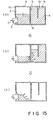
- FIG. 1 - 6 there is shown an ink cartridge having an ink supply opening formed in a wall of a vacuum producing material container that faces a partition wall 5 which cooperates with a bottom surface of the cartridge to form a fine communication port 8.
- Figure 1 is a perspective view of an ink cartridge
- Figure 2 is a sectional view of the ink cartridge.
- the ink cartridge main body 1 is provided with an opening 2 for communication with an ink jet recording head at a position displaced toward the fine communication port in the form of a clearance 8. It comprises a vacuum producing material container 4 for containing the vacuum producing material 3 and an ink container 6 for containing substantially only ink, which communicates with the container 4 at a bottom portion 11 through the clearance 8 provided by the partition wall 5.
- a filter may be provided at an end of the joint member to remove the foreign matter in the ink cartridge.
- ink When the ink jet recording apparatus is operated, ink is ejected out through orifices of the ink jet recording head resulting in an ink absorbing force in the ink cartridge.
- Ink 9 is supplied by the absorbing force from the ink container 6 through the clearance 8 between the bottom end of the partition and the bottom of the ink cartridge 11 to the vacuum producing material container 4, and to the ink jet recording head through the vacuum producing material 3 and the joint member 7.
- the internal pressure or the ink container 6 (which is closed except for the clearance 8)reduces resulting in a pressure difference between the ink container 6 and the vacuum producing material container 4.
- this pressure difference continues to increase.
- the vacuum producing material is open to the ambient air by a clearance 2 between the joint member and the opening. Air is introduced into the ink container 4 through the clearance 8 between the bottom end of the partition member and the internal bottom surface 11 of the ink cartridge through the vacuum producing material.
- the pressure difference between the ink container 6 and the vacuum producing material container is canceled.
- this action is repeated, so that a constant negative pressure (vacuum) is maintained in the ink cartridge.
- Substantially all of the ink in the ink container 6 except for the ink deposited on the internal wall surface of the ink container can be used up, and therefore, the ink use efficiency is improved.
- the capillary force of the vacuum producing material itself meniscus force at the interface between the ink and the vacuum producing material
- the ink retaining state in the vacuum producing material becomes substantially constant.
- the air collected in the ink container is substantially in a certain degree of vacuum, and therefore, the pressure balance in the cartridge is extremely stabilized, so that the ink leakage from the ink jet recording head is suppressed.
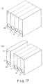
- the ink cartridge in order to use the ink cartridge in a color ink jet recording, various color inks (black, yellow, magenta and cyan) may be accommodated in separate exchangeable ink cartridges, respectively. These ink cartridges may be unified as shown in Figure 17A.
- the exchangeable ink cartridge may comprise a black container exchangeable ink cartridge which is frequently used and one another color exchangeable cartridge, as shown in Figure 17, (B). Any combination is possible in consideration of the ink jet apparatus.
- the following is preferably optimized: material, configuration and dimensions of the vacuum producing material 3, configuration and dimensions of rib end 8, configuration and dimensions of the clearance 8 between the rib end 3 and the ink cartridge bottom 11, volume ratio between the vacuum producing material container 4 and the ink container 6, configuration and dimensions of the joint member 7 and the insertion degree thereof into the ink container, configuration, dimension and mesh of the filter 12, and the surface tension of the ink.
- the material of the vacuum producing member may be any known material if it can retain ink despite the weight thereof, the weight of the liquid (ink) and small vibration.
- the pore density can be adjusted during the manufacturing thereof.
- corresponding pore density foamed materials are required. It is desirable that a foamed material not treated by the thermal compression and having a predetermined number of cells (number of pores per 1 inch) is cut-into a desired dimension, and it is squeezed into the vacuum producing material container so as to provide the desired pore density and the capillary force.
- the clearance is provided between the joint member 7 and the opening 2 for the joint member 7 to permit introduction of the air into the ink cartridge.
- other structures or configurations are usable for the joint member and the joint opening.
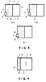
- an end of the joint member 7 is inclined at a certain angle with respect to a joint member inserting direction, since then as shown in Figure 3(a) and (b), the parting of the porous material from the bottom of the ink cartridge is prevented upon insertion of the joint member, and the surface contact between the filter and the vacuum producing material is maintained assuredly. If the insertion amount of the joint member is too large, the tapered end portion might tear the vacuum producing material, and therefore, the surface structure shown in Figure 3, (c), is preferable.
- an outer wall of the joint member is provided with grooves.
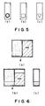
- the configuration of the opening 2 may be a slot (Figure 5, (a)), rectangular ( Figure 5, (b)), triangular ( Figure 5, (c)).
- the preferable configuration of the opening 2 provides a clearance between the joint member, or the configuration is such that it is in contact with the outer periphery of the joint member at the bottom of the opening (bottom of the ink cartridge) and that it is open at the upper portion of the opening.
- the exchangeable ink cartridge has a joint opening functioning also as the air introduction opening, and therefore, the structure is simple.
- the amount of insertion of the joint member 7 into the exchangeable ink cartridge is properly determined by the ordinary skilled in the art so as to provide a compression region of the vacuum producing member to prevent ink leakage upon the insertion and to prevent ink supply stop during the recording operation, in consideration of the configuration of the joint member, the vacuum producing material and the configuration of the ink cartridge.
- the configuration and dimensions of the clearance 8 between the end of the partition wall and the ink cartridge bottom are not limited. However, if it is too small, the meniscus force with the ink is too strong, and although the ink leakage can be prevented through the joint opening, but the ink supply to the vacuum producing material container is difficult, with the possible result of ink supply stop during the use.
- the height to the partition wall of the fine communicating part is preferably larger than an average pore size of the vacuum producing material (average pore size adjacent the fine communication part, preferably) (practically not less than 0.1 mm), and not more than 5 mm. For the purpose of further stabilization, it is preferably not more than 3 mm.
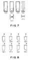
- Figure 7 shows an example of the configuration of the clearance 8.
- Figure 7, (a) shows the most stable structure and configuration.
- Figure 7, (a), (b) and (c), show examples in which the communication part is formed only a part of the entire width of the cartridge, and is waved. This structure is effective when the entire volume of the cartridge is large.
- Figure 7, (d) shows an example having tunnel-like communicating parts with which the ink is easily moved to the inside of the cartridge, and the air introduction can be concentrated.
- a recess is formed along a vertical direction on the partition wall in the ink container. With this structure, the air having come to the bottom end of the partition wall is effectively introduced into the ink container by the recess, thus increasing the air tracking efficiency.
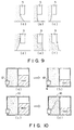
- the clearance 8 is also determined in consideration of the position of the joint opening. Referring to Figure 10, (a) and (b), the partition wall end is at a position lower than the bottom end of the joint opening in Example (a), and the ink retained in the vacuum producing material is lower than the bottom end of the joint opening, and therefore, the leakage preventing effect is sufficient.
- Example (b) the end of the partition wall is at a position higher than the bottom end of the joint opening, and the ink retained in the vacuum producing material is above the bottom end of the joint opening, and therefore, the ink leakage suppressing effect is not sufficient. Therefore, it is preferable to stabilize the advantageous effect of the present invention that the position of the end of the partition wall is not higher than the bottom end of the joint opening by properly determining the dimension of the clearance 8.
- the height of the clearance 8 is selected in the range of 0.1 - 20 mm. Further preferably it ranges from 0.5 - 5 mm approximately.
- the configuration of an end of the partition wall may be any if the consideration is paid to the position relative to the joint opening, as will be understood from Figure 8, (a) - (h).
- the volume ratio between the vacuum producing material container 4 and the ink container 6, is determined in consideration of the ambient condition under which the ink cartridge is used and the ink jet recording apparatus with which it is used. Also, the relation with the used vacuum producing material is important. In order to improve the use efficiency of the ink, it is desirable to increase the volume of the ink container. In that case, a vacuum producing material capable of producing high vacuum (high compression ratio sponge), is effective. Therefore, the preferable ratio ranges from 1:1 - 1:3 practically. In this case, the vacuum producing performance of the vacuum producing member is increased with increase of the relative volume of the ink container.
- the configuration, dimension and mesh of the filter 11 can be properly determined by one skilled in the art depending on the ink jet recording apparatus with which the ink cartridge is used. However, in order to prevent the nozzle from being clogged by the foreign matter introduced from the ink cartridge, the passing area thereof is smaller than the size of the orifice.
- the quantity of the ink in the ink cartridge is not limited except for the internal volume of the ink cartridge.
- the ink may be contained to the extent of the volume limit in the ink container.
- the vacuum producing material is preferably lower than the ink retaining capacity of the material.
- the air and the ink expands in the ink container to push the remaining ink out of the ink cartridge with the possible result of ink leakage.
- the volume of air expansion in the closed ink container including ink expansion (although the amount is small) in accordance with the worst ambient condition change, is estimated, and the amount of the displaced ink from the ink container is to be accommodated in the vacuum producing material container.
- the vacuum producing material container with an air vent in addition to the joint opening, as shown in Figure 10, (c) and (d), since then the ink displaced into the vacuum producing material from the ink chamber by the expansion of the air can be guided toward the air vent.
- the position of the air vent is not limited if it is upper than the joint opening of the vacuum producing member container. However, in order to make the ink flow in the vacuum producing material under the ambient condition change remote from the joint opening, it is preferably away from the joint opening.
- the number, configuration and size of the air vent is properly determined by a person skilled in the art in consideration of the ink evaporation or the like.
- the joint opening and/or the air vent is hermetically sealed by a sealing member to prevent ink evaporation or to be prepared for the expansion of the air in the ink cartridge.
- the sealing member may be a single layer barrier which is so-called barrier material in the packing field, a compound plastic film having several layers, or such material reinforced by paper or cloth or another reinforcing material or aluminum foil It is preferable that a bonding layer of the same material as the main body of the ink cartridge is used to fuse fixing the barrier material, thus improving the hermetical sealing property.
- the packing member may preferably be of the same barrier material as described with respect to the sealing member in consideration of the permeabilities of the liquid and the air.
- the ink does not leak out during the transportation of the ink cartridge itself.
- the material of the main body of the ink cartridge may be any known moldable material if it does not have any adverse influence to the ink jet recording ink or if it has been treated for avoiding the influence.
- the productivity of the ink cartridge is also considered.
- the main body of the ink cartridge is separated into a bottom portion 11 and an upper portion, and they are respectively integrally molded from plastic resin material.
- the vacuum producing material is inserted thereinto, and thereafter, the bottom portion and upper portion are fuse-bonded, thus providing the main body of the ink cartridge.
- the plastic material is transparent or semitransparent, the ink in the ink container can be observed externally, and therefore, the timing of ink cartridge change may be expected.
- the outer surface of the main body of the ink cartridge may be grained.
- the ink can be loaded through pressurizing or pressure-reduction method. Provision of an ink filling opening in either of the containers of the containing main assembly is preferable since then the ink cartridge opening is not contaminated. After the filling, the ink filling opening is plugged by plastic or metal plug.
- the exchangeable ink cartridge is reliable during the transportation thereof, and a high use efficiency ink cartridge can be provided with a simple structure.
- the proper vacuum from the start to the end of the use can be maintained when the recording operation is carried out or is not carried out, while permitting high speed recording.
- the exchangeable ink cartridge of this invention is easy to handle so that the ink does not leak out when it is loaded into the ink jet recording apparatus, and the possibility of erroneous operation can be avoided.
- Figure 11 illustrates a manufacturing method of an ink container cartridge.
- a main body of the cartridge (left down hatching) comprises a partition plate 61 and two containers separated by the partition wall 5.
- An ink absorbing material 4 functioning as the vacuum producing material is inserted into the container portion which is close to the opening 2.
- a bottom member 11 functioning as the covering member is unified to the main body.
- This Figure also shows the state in which the recording head HD is loaded in the ink cartridge 1.
- the ink cartridge 1 is partitioned into two chambers by a partition wall 5, and the bottom portion is covered by a flat bottom member 11 constituting the bottom of the ink cartridge.
- the fine communication port 8 can be provided by the end of the partition wall.
- the air vent 10 is disposed on the same surface as having the opening 2, but above the opening.
- the joint portion 7 functioning as the supply pipe is inserted into the opening of the ink cartridge, and the recording head is mounted thereto.
- the joint portion 7 is inclined so that the top portion is further forward than the bottom portion.
- the ink passage in the joint portion is in the form of a horn opening upwardly in the Figure. With this structure, the ink can be properly supplied to the recording head from the ink absorbing material.
- the ink jet recording apparatus comprises heat generating element 72 for producing thermal energy to eject the ink through ejection outlets 71 of the nozzles 73, wherein the thermal energy is effective to cause state change in the ink.
- heat generating element 72 for producing thermal energy to eject the ink through ejection outlets 71 of the nozzles 73, wherein the thermal energy is effective to cause state change in the ink.
- a high density and fine images can be provided by the stabilized ink supply performance, particularly in the case of color recording.
- the proper vacuum is maintained from the start to the end of the use thereof when the recording operation is carried out or is not carried out, when permitting high speed recording operation.
- the ink leakage can be prevented under the use condition of the ink jet recording apparatus.
- the exchangeable ink cartridge is easy to handle, and the ink does not leak out when it is mounted or demounted relative to the ink jet recording apparatus. Therefore, the erroneous operation in the mounting thereof can be avoided.
- the manufacturing method of the ink cartridge will be described further.
- the closed structure ink chamber (although there is fine communication port between the ink containing chamber and the negative pressure producing material containing chamber, the ink is discharged only when the air and the ink are exchanged with each other), and the vacuum producing material containing chamber are integrally molded, the ink is filled through an opening 13 at the ink container chamber side in the covering member 11.
- the ink is supplied in this manner, a substantial part of the vacuum producing material 4 receives the ink through the fine communication port.
- the region of the vacuum producing material 4 adjacent the air vent is not supplied with the ink to provide ink-free region. Thereafter, the opening 13 is sealed by a ball 14. Then, the opening 2 and the air vent are sealed by the same sealing member S (it may be separate members).
- FIG 12 shows such an ink jet cartridge before start of use.
- the ink container 6 is filled with an ink.
- Figure 12 shows the closed state ink jet cartridge 1 with the printer which is used therewith.
- a region 3A of the vacuum producing material adjacent to the air vent portion 10 does not contain the ink at an upper portion of the cartridge.
- a region 3B of the vacuum producing material below the region 3A is compressed by insertion of the ink supply pipe (not shown).
- the vacuum producing material portion other than those regions 3A and 3B, are not externally influenced and simply functions to retain the ink.
- the region 3B is faced to the opening 2 for the ink supply to the recording head provided on the same surface but below the air vent 10.
- the opening is above the fine communication port 8, and the above-described structure is used.
- the cartridge 1 of Figure 12 becomes usable by removing the sealing member S. Since the region A does not retain the ink, the ink does not leak out even if the vibration or pressure change is imparted upon the removal of the sealing member.
- the ink is not retained in the region of the vacuum producing member that is close to the air vent or air communication port, irrespective of whether the ink cartridge is being used or not used.
- the leakage of the ink from the ink cartridge through the air vent can be prevented even when the ambient condition varies.
- the sealing member closes the air vent the sealing member can be prevented from peeling off.
- the region is effective to permit air supply corresponding to the consumption of the ink, so that the change of the vacuum in the ink cartridge can be suppressed. If the region of the vacuum producing material adjacent to the air vent has never been wetted by the ink at all, it is preferable to decelerate the ink seeping speed. However, the region thereof may be wetted by the ink beforehand, and thereafter, the ink may be removed from this region.
- the ink supply opening or the compressed part of the vacuum producing material (compressible) by the ink supply pipe is present at a side opposed to the partition wall constituting the fine communication port, by which the effective ink supply path can be stably provided in the vacuum producing material in the second accommodation chamber. This can be further stabilized by placing the ink supply opening above the fine communication port relative to the bottom surface of the ink cartridge.
- the ink moving direction can be substantially made constant, and therefore, the ink can be completely consumed from the second chamber, that is, the ink container chamber.
- the ink container chamber After the ink in the ink container chamber has been used up, air moves the ink toward the opening from the partition wall in the direction to cancel the vacuum in the ink container chamber, as a result, the ink in the vacuum producing material can be consumed further, thus minimizing the nonusable remaining amount of the ink.
- the non-compressed region provides a one-way ink path, and the ink retaining capacity of the compressed region can further reduce the remaining amount of the ink.
- the ink jet printer is provided with a recording head recovery means HR which carries out ink ejection or ink sucking by sucking means automatically or manually in response to mounting of the cartridge 1 thereto.
- a recording head recovery means HR which carries out ink ejection or ink sucking by sucking means automatically or manually in response to mounting of the cartridge 1 thereto.
- the ink cartridge 1 mounted to the ink jet head HD mounted on a scanning type carriage CR has been deprived of the sealing tape.
- the cartridge mounted on the carriage CR receives through the opening 2 the ink supply pipe, by which the vacuum producing material 3 is compressed in the compressible region 3b.
- the vacuum producing member 3 is deformed toward the fine communication port 8.
- the mounting of the container is detected by detecting means (not shown) in the form of mechanical or electrical detecting means, which produces mounting signal IT into the printer control means CC.
- the recovery means HR is actuated before the start of the recording operation to discharge the ink in the ink cartridge, thus improving the state of the ink in the ink cartridge.
- FIG 13 (A) and (B) show an inclination range capable of printing operation or ink supply.
- Designated by a reference numeral 40 is a horizontal line. It is preferable that the fine communication port is at a lower position. Ideally, the bottom surface of the cartridge is parallel with the horizontal plane 40. Practically, however, in the case of two chamber structure as in this embodiment, the inclination is permissible in the range, 0 ⁇ ⁇ ⁇ 15 degrees. When it is reciprocated on a scanning carriage, it is preferably 0 ⁇ ⁇ ⁇ 5 degrees.
- the vacuum producing material used be constituted by a plurality of vacuum producing material members. However, in that case, the resultant interface between the members might permit movement of the air at the interface, as the case may be. In view of this, single porous material member is preferable for the vacuum producing material.
- the ink container performs it function if it has an ink capacity larger than that of the vacuum producing material accommodating chamber.
- the description will be made as a partition plate 61 in the ink accommodating chamber.
- the external wall of the cartridge may be deformed with the possible result that the ink is leaked through the orifice from the ink jet recording head or that the ink is leaked out through the air vent provided for equalizing the pressure in the cartridge with the ambient pressure.
- this problem is solved, thus preventing the ink leakage during the handling or during the transportation or even if the temperature or the pressure changes.
- the use efficiency is still high.
- Figure 14 (A) is a perspective view of the ink container of this embodiment, and Figure 14, (B), is a sectional view thereof.
- Figure 15 illustrates ink supply operation of this embodiment.
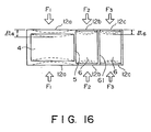
- Figure 16 illustrates deformation of the side wall when it receives load.
- the main body of the ink cartridge 1 comprises an opening 2 for communication with the ink jet recording head and an air vent 10 for permitting introduction of the air, disposed above the opening 2, vacuum producing material 3 for retaining the ink for the recording, a vacuum producing material container 4 for containing the vacuum producing material 3 and provided with the opening 2 and the air vent 10, and an ink container (chamber) 6 for containing the ink in communication with the vacuum producing material container 4 through a clearance below a rib 5.
- the ink container 6 and the vacuum producing material container 4 communicate with each other through a clearance 8 formed between an end of the rib 5 and the bottom surface.
- a partition plate 61 connects the opposite side walls leaving a gap not less than the clearance 8 at the bottom.
- FIG 15 is a sectional view in the state in which the ink jet recording apparatus is operable after a joint member 7 for supplying the ink to the ink jet recording head is inserted into the opening 2 of the ink cartridge main body 1 to press-contact the vacuum producing material 3.
- the end opening of the joint member 7 may be provided with a filter to remove foreign matters in the ink cartridge.
- ink jet recording apparatus When the ink jet recording apparatus is operated, ink is ejected through the orifice of the ink jet recording head, so that ink absorbing force is produced in the ink container.
- the ink 9 is supplied to the ink jet recording head from the ink container 6 through the clearance 8 between an end of the rib 5 and the bottom of the ink cartridge 11 to the vacuum producing material container 4, and through the vacuum producing material 3 to the joint member 7.
- the pressure of the ink container 6 which is closed except for the clearance 8, reduces with the result of pressure difference between the ink container 6 and the vacuum producing material container 4.
- the pressure difference continues to increase since the vacuum producing material container 4 is open to the air through the air vent 10.
- the capillary force of the vacuum producing material 3 itself appears to prevent the leakage of the ink from the ink jet recording head.
- the ink cartridge it is desirable that the ink cartridge is durable against external force and the ambient condition change during the transportation, while maintaining high use efficiency.
- the amount of deformations are equivalent in the vacuum producing member container 4 and the ink container 6 when the external forces are applied to the side walls 12a, 12b and 12c.
- the cartridge is usually made by molding a plastic material.
- the thickness of the side wall 12a of the vacuum producing material container 4 is larger than the thickness of the side walls 12b and 12c of the ink container portion 6, and a partition wall (rib) 61 is disposed to extend between the opposite side walls, leaving the clearance at the bottom, at a position to divide the space into two equal spaces in the ink container 6.
- the deformation ⁇ t6 of the wall responsive to the equivalent loads per unit area is reduced , and the deformations of the side walls 12b and 12c at the opposite ends of the rib 61, are equivalent.
- the amount of deformation ⁇ t4 of the vacuum producing material container 4 equivalent thereto, the leakage of the ink due to the deformation of the wall can be prevented.
- the material of the wall is polypropylene (PP), and the outer dimensions are as follows: 48 mm in length, 55 mm in height, 11 mm in thickness. In this case, it is divided into the vacuum producing material container 4 and the ink container 6 substantially at the center of the length of 48 mm.
- the side wall 12a of the vacuum producing material container 4 has a thickness of 1.5 mm
- the side walls 12b and 12c of the ink container 6 have a thickness of 1 mm
- the rib 61 of the ink container 6 is disposed approx. 10 mm away from the wall surface.
- only one rib 61 is provided in the ink container 6 because of the size of the ink container.
- the number thereof is not limited, and two ribs 61 may be provided in accordance with the size of the ink cartridge.
- the number, position and the wall thickness of the rib can be properly determined by those skilled in the art.
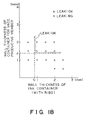
- Figure 18 shows the relation of the ink leakage during the handling and the transportation with the wall thickness of the vacuum producing material container 4 and wall thicknesses of various walls, investigated for the purpose of determining the wall thickness of the ink container 6.
- the above-described dimension may be determined on the basis of the data of this Figure. It is preferable that the wall thickness of the vacuum producing material container 4 is 1.3 - 3 times the wall thickness of the ink container 6.
- embodiments of the present invention enable the provision of an exchangeable ink cartridge, an ink jet head and a printer using the same capable of effecting high speed recording, while the vacuum can be maintained substantially constant during a large part of the period from the start to the end of use of the ink cartridge.
- an exchangeable ink cartridge in accordance with the present invention enable a vacuum to be produced in the ink cartridge when the recording operation is not effected, thus preventing ink leakage through an opening upon impact.
- inventions of the present invention provide exchangeable ink cartridges which are less expensive and from which ink does not leak during transportation.
- An ink cartridge embodying the invention is usually handled by an operator, and therefore, it is possible that strong forces are applied thereto with the result of deformation of the ink container wall.
- an additional partition wall providing a larger clearance than the fine communication port in the ink container for containing substantially only the ink is provided.
- the thickness of the wall of the chamber containing substantially only ink is 0.8mm or more and that the wall thickness of the chamber containing the vacuum producing material such as sponge is 1.3mm from the standpoint of the prevention of the deformation.
- ink is forcibly discharged by sucking the ink by the sucking means and by ejecting the ink by ejecting means automatically or manually upon mounting of the cartridge on the ink jet printer.
- This is preferable because the state of the ink in the vacuum generating material can be adjusted before the start of the printing operation, and therefore, the printing function can be performed without influence of the ink cartridge keeping state.
- the height of the fine communication port provided by the partition wall is larger than an average pore size of the vacuum producing material (preferably the average pore size in the region adjacent the fine communication port) (practically not less than 0.1 mm), and it is preferably not less than 5 mm. If it is less than 3 mm, further stabilization can be expected.
- the volume ratio of the vacuum producing material container and the ink container is not less than 1:1 and not more than 1:3, practically.
Abstract
Description
- The present invention relates to an ink cartridge connectable to an ink jet head, a method of manufacturing such a cartridge and a printer using the cartridge, and which is usable with a copying machine, a facsimile machine or any other recording apparatus, communication apparatus, office equipment, combined machine or printer.
- Heretofore, an ink cartridge for an ink jet recording apparatus has been integrally formed with an ink jet head, and when the ink in the cartridge is used up, the unified end and the container are disposed of. The quantity of the ink remaining in the cartridge is decided by the ink retaining capacity of a sponge (vacuum producing material) occupying the entirety of the space in the cartridge, and it is relatively large. Japanese Laid-Open Patent Application No. 87242/1988 (JP-A-63 087 242) discloses such an ink container. The ink container contains a foamed material, and is integral with an ink jet recording head having a plurality of ink ejection orifices. In such an ink container, in order to accommodate the ink in the porous material such as foamed polyurethane material, the production of the vacuum and the ink retention (prevention of ink leakage from the ink container) are accomplished by the capillary force of the foamed material. However, the foamed material is required to fill the entirety of the ink container, and therefore, the quantity of the ink therein is limited, and the quantity of the non-usable ink is relatively large. This means that the ink use efficiency is low. It is difficult to detect the amount of the ink remaining therein. In addition, during the ink consumption period, the negative pressure gradually changes, and therefore, it is difficult to maintain a substantially constant vacuum.
- Japanese Laid-Open Patent Application No. 522/1990 (JP-A-2 000 522) discloses an ink cartridge containing substantially only ink. More particularly, it discloses an integral ink jet recording head and ink cartridge, comprising a primary ink container for containing a large amount of the ink at an upper position, and a small amount of porous material between the container and the ink jet recording head therebelow. It is stated that the ink use efficiency is improved because only the ink is disposed in the ink passage without the porous material contained in the ink container. In addition, a secondary ink container capable of containing the ink is provided at the side of the porous material, which is effective to receive ink flowing from the primary ink container due to expansion of the air in the primary ink container upon temperature rise (pressure decrease), so as to maintain a substantially constant negative pressure of the recording head during the recording operation.
- In this structure, when the recording operation is not carried out, the porous material is filled with a very large amount of the ink from the primary ink container which contains a large amount of the ink above the porous material, and therefore, the porous material itself can hardly produce negative pressure. For this reason, ink leaks out of the orifice of the ink jet recording head under small impacts, and therefore, it is not practical. If this container is used as an exchangeable ink cartridge to be mounted to an ink jet recording head, ink can leak out of the porous material, and therefore, it is still not practical.
- In another ink cartridge, the ink is sealingly contained in a bladder, and the negative pressure of the bladder is maintained constant using a spring structure, but this is expensive, and it is difficult to mass-produce with the correct performance of the spring structure. In the field of ink jet printing (non-contact type printing) inexpensive ink cartridges which perform accurately have not been achieved, and have long been desired.
- The inventors have investigated from the standpoint of capability of properly supplying ink corresponding to the ejection of ink from the recording head during a printing operation and also from the standpoint of the capability of preventing ink leakage through the ejection outlet when a printing operation is not being carried out. In particular, the inventors have proposed a cartridge which comprises a first container containing a vacuum producing material and provided with an air vent and a second container for containing substantially only the ink to be supplied to the first container, the second container being substantially hermetically closed with the exception of the communication with the first container.
- Japanese Laid-Open Utility Model Application No. 16385/1985 (JP-U- 60 016 385) discloses a recording pen having a recording tip which is contacted to a recording material during the recording operation. The recording tip has an ink absorbing and retaining capability, and ink is supplied thereto. Therefore, the recording tip is exposed to the ambient air, in contrast to the ink jet recording apparatus. The Japanese Laid-Open Utility Model Application is directed only to the overflow of ink through the recording tip.
- It comprises as essential elements a first liquid absorbing material, and a second absorbing material which absorbs less ink than the first absorbing material although it absorbs a small amount of the ink, the second absorbing material being disposed above the first absorbing material at a position closer to the air vent in a central chamber from which the recording tip projects downwardly, and ink being supplied to opposite sides of the chamber from hermetically closed ink accommodating chambers. With this structure, when air in the closed ink container expands due to ambient temperature rise with the result that ink in the ink chambers flows into the first absorbing material, ink incapable of being retained by the first absorbing material is absorbed by the second absorbing material, so that overflow droplets of ink from the writing tip can be prevented. It also discloses provision of a constant width groove which is effective, when one of the two closed ink chambers contains only air, to permit expanded air to escape through the air vent. The groove extends from the bottom end to the top end on a side surface other than the partition wall between the central chamber and the closed ink container. If this were to be used for an ink jet recording head, ink leakage through the air vent would be expected and this has been confirmed. This leakage arises because of the fundamental difference between contact recording and non-contact recording. This problem does not arise in the field of recording pens. In addition, the constant width groove serves to promote the discharge of the ink together with the air, and therefore, leakage of the ink through the air vent has been promoted.
- Additionally, the ink consumption of the two ink containers is not the same. If one of the containers empties first, the ink jet recording operation is no longer possible despite the fact that a large amount of ink remains in the other ink container. This is because a large amount of air is introduced into the first absorbing material with the result of incapability of the ink supply.
- With a view to alleviating the above problems, the present inventors have developed new structures of ink cartridge which are disclosed in our co-pending British patent applications nos 9607543.7, 9626088.0, 9626090.6 and 9626089.8, published as GB-A-2 297 524 on 07/08/96, GB-A-2 305 398 on 04/09/97, GB-A-2 305 635 on 16/04/97 and GB-A-2 305 634 on 16/04/97, and claiming the same priority as the present application
- Those cartridges all comprise a first chamber containing negative pressure producing material and having an air vent and an ink supply port and a second chamber providing a printing liquid reservoir for the first chamber and communicating with the first chamber via a communication port.
- The present invention concerns an advantageous process for manufacturing such cartridges.
- According to one aspect of the present invention there is provided a method of manufacturing an ink cartridge having an ink outlet connectable to an ink jet head for an ink jet recording apparatus and an air vent, which method comprises providing a one-piece body defining first and second compartments separated by a partition wall, inserting a negative pressure producing material into the first compartment and sealing a covering member to the one-piece body to close the first and second compartments so that the covering member forms with the first compartment a first chamber having the ink outlet and the air vent, and the covering member forms with the second compartment a second chamber which provides an ink reservoir for the first chamber and which is closed except for a communication port between the first and second chambers and defined between the partition wall and the covering member.
- In another aspect, the present invention provides a method of manufacturing an ink cartridge having an ink outlet connectable to an ink jet head for an ink jet recording apparatus and an air vent, which method comprises providing a one-piece body having, in use, front, back, top and two side walls and a partition wall extending between the two side walls so as to separate the one-piece body into a first compartment formed by said partition, front, top and two side walls and a second compartment formed by said partition, back, top and two side walls; inserting a sponge-like absorbent negative pressure producing material into said first compartment through the open bottom of the one-piece body; and sealing a bottom covering member to said one-piece member so that said bottom covering member forms with said first compartment a first chamber containing said absorbent material and having the ink outlet and air vent, and said bottom member forms with said second compartment a second chamber which provides an ink reservoir for said first chamber and said bottom wall and said partition wall define an opening providing a communication port between said first and second chambers.
- The present invention further provides an ink cartridge having an ink outlet connectable to an ink jet head for an ink jet recording apparatus and an air vent, which cartridge comprises a one-piece body defining first and second compartments separated by a partition wall, a negative pressure producing material in the first compartment and a covering member sealed to the one-piece body to close the first and second compartments so that the covering member forms with the first compartment a first chamber having the ink outlet and the air vent, and the covering member forms with the second compartment a second chamber which provides an ink reservoir for the first chamber and which is closed except for a communication port between the first and second chambers and defined between the partition wall and the covering member.
- In addition, the present invention provides an ink cartridge having an ink outlet connectable to an ink jet head for an ink jet recording apparatus and an air vent, which cartridge comprises a one-piece body having front, back, top and two side walls and a partition wall extending between the two side walls so as to separate the one-piece body into a first compartment formed by said partition, front, top and two side walls and a second compartment formed by said partition, back, top and two side walls; a sponge-like absorbent negative pressure producing material in said first compartment; and a bottom covering member sealed to said one-piece body so that said bottom covering member forms with said first compartment a first chamber containing said absorbent material and having the ink outlet and the air vent, said bottom member forms with said second compartment a second chamber forming an ink reservoir for said first chamber and said bottom wall and said partition wall define an opening providing a communication port between said first and second chambers.
- Embodiments of the invention will now be described, by way of example, with reference to the accompanying drawings, in which:
- Figure 1 is a schematic partly broken perspective view of an ink cartridge.
- Figure 2 is a sectional view of the ink cartridge of Figure 1.
- Figure 3 shows examples of connection between the cartridge and the supply pipe.
- Figure 4 illustrates a comparison example.
- Figure 5 illustrates ink supply part of the cartridge of Fig. 1.
- Figure 6 illustrates a positional relationship between an ink supply portion and a fine communication port.
- Figure 7 illustrates the structure of the fine communication part.
- Figure 8 illustrates configuration of a partition wall at a side of the fine communication port.
- Figure 9 illustrates state of the absorbing material at an end adjacent the partition wall.
- Figure 10 illustrates the state of the inside of the absorbing material against changes in the ambient condition.
- Figure 11 illustrates a manufacturing method according to an embodiment of the present invention, and illustrates an ink jet head.
- Figure 12 illustrates an ink jet printer and an ink cartridge usable therewith.
- Figure 13 is a sectional view illustrating permissible inclination in use, of the ink cartridge.
- Figure 14 shows the configuration of the cartridge in an embodiment of the present invention.
- Figure 15 illustrates the change in the printing operation.
- Figure 16 illustrates pressure to the external wall of the cartridge
- Figure 17 is a perspective view of a color ink container according to an embodiment of the present invention.
- Figure 18 is a graph showing the relation between the thickness of the wall and ink leakage by the external pressure.
-
- Referring to Figures 1 - 6, there is shown an ink cartridge having an ink supply opening formed in a wall of a vacuum producing material container that faces a
partition wall 5 which cooperates with a bottom surface of the cartridge to form afine communication port 8. - Figure 1 is a perspective view of an ink cartridge, and Figure 2 is a sectional view of the ink cartridge.
- As shown in Figures 1 and 2, the ink cartridge
main body 1 is provided with anopening 2 for communication with an ink jet recording head at a position displaced toward the fine communication port in the form of aclearance 8. It comprises a vacuum producingmaterial container 4 for containing thevacuum producing material 3 and anink container 6 for containing substantially only ink, which communicates with thecontainer 4 at abottom portion 11 through theclearance 8 provided by thepartition wall 5. - With this structure, air is supplied through the
opening 2. However, what is important is that ink is supplied assuredly from theink container 6 through thecommunication port 8 toward theopening 2 along the bottom 11 of the ink cartridge. With the ink supply, air is introduced in place of the ink in theink container 6. The description will be made as to the compressing deformation of the vacuum or negative pressure producing material by the supply pipe in the compressing deformation capable region adjacent the opening. In Figure 3, ajoint member 7 functioning as a supply pipe for supplying ink to the ink jet recording head has been inserted into an exchangeable ink cartridge - With this state, the
joint member 7 is press-contacted to the vacuum producing member, and the ink jet recording apparatus is operable in this respect. A filter may be provided at an end of the joint member to remove the foreign matter in the ink cartridge. - When the ink jet recording apparatus is operated, ink is ejected out through orifices of the ink jet recording head resulting in an ink absorbing force in the ink cartridge.
Ink 9 is supplied by the absorbing force from theink container 6 through theclearance 8 between the bottom end of the partition and the bottom of theink cartridge 11 to the vacuum producingmaterial container 4, and to the ink jet recording head through thevacuum producing material 3 and thejoint member 7. - By this ink supply, the internal pressure or the ink container 6 (which is closed except for the clearance 8)reduces resulting in a pressure difference between the
ink container 6 and the vacuum producingmaterial container 4. With the continuing recording operation, this pressure difference continues to increase. However, the vacuum producing material is open to the ambient air by aclearance 2 between the joint member and the opening. Air is introduced into theink container 4 through theclearance 8 between the bottom end of the partition member and theinternal bottom surface 11 of the ink cartridge through the vacuum producing material. At this time, the pressure difference between theink container 6 and the vacuum producing material container is canceled. During the recording operation, this action is repeated, so that a constant negative pressure (vacuum) is maintained in the ink cartridge. Substantially all of the ink in theink container 6 except for the ink deposited on the internal wall surface of the ink container, can be used up, and therefore, the ink use efficiency is improved. - When the recording operation is not performed, the capillary force of the vacuum producing material itself (meniscus force at the interface between the ink and the vacuum producing material) and the like are produced. Particularly, when the ink consumption from the ink container is started, the ink retaining state in the vacuum producing material becomes substantially constant. The air collected in the ink container is substantially in a certain degree of vacuum, and therefore, the pressure balance in the cartridge is extremely stabilized, so that the ink leakage from the ink jet recording head is suppressed.
- If the vacuum producing material is properly selected in accordance with the ink jet recording head to be used therewith and if the volume ratio between the vacuum producing material container and the ink container, are properly determined, the structure shown in Figure 4 is possible.
- As shown in Figure 17, in order to use the ink cartridge in a color ink jet recording, various color inks (black, yellow, magenta and cyan) may be accommodated in separate exchangeable ink cartridges, respectively. These ink cartridges may be unified as shown in Figure 17A. The exchangeable ink cartridge may comprise a black container exchangeable ink cartridge which is frequently used and one another color exchangeable cartridge, as shown in Figure 17, (B). Any combination is possible in consideration of the ink jet apparatus. In this exchangeable ink cartridge in order to control the vacuum, the following is preferably optimized: material, configuration and dimensions of the
vacuum producing material 3, configuration and dimensions ofrib end 8, configuration and dimensions of theclearance 8 between therib end 3 and the ink cartridge bottom 11, volume ratio between the vacuum producingmaterial container 4 and theink container 6, configuration and dimensions of thejoint member 7 and the insertion degree thereof into the ink container, configuration, dimension and mesh of thefilter 12, and the surface tension of the ink. - The material of the vacuum producing member may be any known material if it can retain ink despite the weight thereof, the weight of the liquid (ink) and small vibration. For example, there are sponge like material made of fibers and porous material having continuous pores. It is preferably in the form of a sponge of polyurethane foamed material which is easy to adjust the vacuum and the ink retaining power. Particularly, in the case of the foamed material, the pore density can be adjusted during the manufacturing thereof. When the foamed material is subjected to thermal compression treatment to adjust the pore density, the decomposition is produced by the heat with the result of changing the nature of the ink with the possible result of adverse influence to the record quality, and therefore, cleaning treatment is desirable. For the purpose meeting various ink cartridges for various ink jet recording apparatuses, corresponding pore density foamed materials are required. It is desirable that a foamed material not treated by the thermal compression and having a predetermined number of cells (number of pores per 1 inch) is cut-into a desired dimension, and it is squeezed into the vacuum producing material container so as to provide the desired pore density and the capillary force.
- In this example, the clearance is provided between the
joint member 7 and theopening 2 for thejoint member 7 to permit introduction of the air into the ink cartridge. However, other structures or configurations are usable for the joint member and the joint opening. In the case that on the vacuum producing material is a porous material such as sponge, it is preferable that an end of thejoint member 7 is inclined at a certain angle with respect to a joint member inserting direction, since then as shown in Figure 3(a) and (b), the parting of the porous material from the bottom of the ink cartridge is prevented upon insertion of the joint member, and the surface contact between the filter and the vacuum producing material is maintained assuredly. If the insertion amount of the joint member is too large, the tapered end portion might tear the vacuum producing material, and therefore, the surface structure shown in Figure 3, (c), is preferable. - It will be considered that an outer wall of the joint member is provided with grooves. As shown in Figure 5, the configuration of the
opening 2 may be a slot (Figure 5, (a)), rectangular (Figure 5, (b)), triangular (Figure 5, (c)). The preferable configuration of theopening 2 provides a clearance between the joint member, or the configuration is such that it is in contact with the outer periphery of the joint member at the bottom of the opening (bottom of the ink cartridge) and that it is open at the upper portion of the opening. - As described in the foregoing, the exchangeable ink cartridge has a joint opening functioning also as the air introduction opening, and therefore, the structure is simple. The amount of insertion of the
joint member 7 into the exchangeable ink cartridge is properly determined by the ordinary skilled in the art so as to provide a compression region of the vacuum producing member to prevent ink leakage upon the insertion and to prevent ink supply stop during the recording operation, in consideration of the configuration of the joint member, the vacuum producing material and the configuration of the ink cartridge. - In the foregoing example , it is effective to provide an air vent in the vacuum producing material container, since then the region of the vacuum producing material that does not contain the ink is easily located adjacent the air introduction passage. The reliability in the ink jet recording apparatus against the ambient condition change is improved. The configuration and dimensions of the
clearance 8 between the end of the partition wall and the ink cartridge bottom, are not limited. However, if it is too small, the meniscus force with the ink is too strong, and although the ink leakage can be prevented through the joint opening, but the ink supply to the vacuum producing material container is difficult, with the possible result of ink supply stop during the use. If it is too large, the opposite phenomenon occurs, and therefore, the height to the partition wall of the fine communicating part is preferably larger than an average pore size of the vacuum producing material (average pore size adjacent the fine communication part, preferably) (practically not less than 0.1 mm), and not more than 5 mm. For the purpose of further stabilization, it is preferably not more than 3 mm. Figure 7 shows an example of the configuration of theclearance 8. Figure 7, (a), shows the most stable structure and configuration. - It is formed with a constant height over the entire width of the cartridge. Figure 7, (a), (b) and (c), show examples in which the communication part is formed only a part of the entire width of the cartridge, and is waved. This structure is effective when the entire volume of the cartridge is large. Figure 7, (d) shows an example having tunnel-like communicating parts with which the ink is easily moved to the inside of the cartridge, and the air introduction can be concentrated. In the examples of Figure 7, (e) and (f), a recess is formed along a vertical direction on the partition wall in the ink container. With this structure, the air having come to the bottom end of the partition wall is effectively introduced into the ink container by the recess, thus increasing the air tracking efficiency.
- The
clearance 8 is also determined in consideration of the position of the joint opening. Referring to Figure 10, (a) and (b), the partition wall end is at a position lower than the bottom end of the joint opening in Example (a), and the ink retained in the vacuum producing material is lower than the bottom end of the joint opening, and therefore, the leakage preventing effect is sufficient. In Example (b), the end of the partition wall is at a position higher than the bottom end of the joint opening, and the ink retained in the vacuum producing material is above the bottom end of the joint opening, and therefore, the ink leakage suppressing effect is not sufficient. Therefore, it is preferable to stabilize the advantageous effect of the present invention that the position of the end of the partition wall is not higher than the bottom end of the joint opening by properly determining the dimension of theclearance 8. Although it is dependent on the configuration and dimensions of the exchangeable ink cartridge, the height of theclearance 8 is selected in the range of 0.1 - 20 mm. Further preferably it ranges from 0.5 - 5 mm approximately. The configuration of an end of the partition wall may be any if the consideration is paid to the position relative to the joint opening, as will be understood from Figure 8, (a) - (h). - As regards the boundary between the end of the
partition wall 5 and thevacuum producing material 3, various structures are considered. This is shown in Figure 9. In the structure of Figure 9, (a) - (d), the vacuum producing material is not compressed by the end of the partition wall, and the density of the vacuum producing material is not locally increased, and therefore, the flow of the ink and the air is relatively smooth, and for this reason, it is preferable for a high speed recording or color recording. On the other hand, the examples of Figures 9, (e), (f), thevacuum producing material 3 compressed by the end of the partition wall, and the density of the material is increased, and therefore, the flow of the ink and the air is obstructed, but the ink leakage or the like can be effectively prevented against slight ambient condition change. Therefore, they are properly determined by one skilled in the art, on the basis of the ink jet recording apparatus with which the ink cartridge is used and the ambient condition under which the ink cartridge is used. - The volume ratio between the vacuum producing
material container 4 and theink container 6, is determined in consideration of the ambient condition under which the ink cartridge is used and the ink jet recording apparatus with which it is used. Also, the relation with the used vacuum producing material is important. In order to improve the use efficiency of the ink, it is desirable to increase the volume of the ink container. In that case, a vacuum producing material capable of producing high vacuum (high compression ratio sponge), is effective. Therefore, the preferable ratio ranges from 1:1 - 1:3 practically. In this case, the vacuum producing performance of the vacuum producing member is increased with increase of the relative volume of the ink container. - The configuration, dimension and mesh of the
filter 11 can be properly determined by one skilled in the art depending on the ink jet recording apparatus with which the ink cartridge is used. However, in order to prevent the nozzle from being clogged by the foreign matter introduced from the ink cartridge, the passing area thereof is smaller than the size of the orifice. - The quantity of the ink in the ink cartridge is not limited except for the internal volume of the ink cartridge. In order to maintain the proper negative structure immediately after the exchangeable ink cartridge is unpacked, the ink may be contained to the extent of the volume limit in the ink container. However, the vacuum producing material is preferably lower than the ink retaining capacity of the material.
- In the ink cartridge having a closed system ink container, when an external ambient condition change such as temperature rise or pressure reduction, occurs when it is loaded in the ink jet recording apparatus, the air and the ink expands in the ink container to push the remaining ink out of the ink cartridge with the possible result of ink leakage. However, in the exchangeable ink cartridge as described, the volume of air expansion in the closed ink container, including ink expansion (although the amount is small) in accordance with the worst ambient condition change, is estimated, and the amount of the displaced ink from the ink container is to be accommodated in the vacuum producing material container. In this case, it is very effective to provide the vacuum producing material container with an air vent in addition to the joint opening, as shown in Figure 10, (c) and (d), since then the ink displaced into the vacuum producing material from the ink chamber by the expansion of the air can be guided toward the air vent. The position of the air vent is not limited if it is upper than the joint opening of the vacuum producing member container. However, in order to make the ink flow in the vacuum producing material under the ambient condition change remote from the joint opening, it is preferably away from the joint opening. The number, configuration and size of the air vent is properly determined by a person skilled in the art in consideration of the ink evaporation or the like.
- During transportation of the ink cartridge itself, it is preferable that the joint opening and/or the air vent is hermetically sealed by a sealing member to prevent ink evaporation or to be prepared for the expansion of the air in the ink cartridge. The sealing member may be a single layer barrier which is so-called barrier material in the packing field, a compound plastic film having several layers, or such material reinforced by paper or cloth or another reinforcing material or aluminum foil It is preferable that a bonding layer of the same material as the main body of the ink cartridge is used to fuse fixing the barrier material, thus improving the hermetical sealing property.
- In order to suppress the evaporation of the ink from the ink cartridge and the introduction of the air thereinto, it is effective that the air in the pack is removed after the ink cartridge is inserted therein. The packing member may preferably be of the same barrier material as described with respect to the sealing member in consideration of the permeabilities of the liquid and the air.
- By proper selection of the packing, the ink does not leak out during the transportation of the ink cartridge itself.
- The material of the main body of the ink cartridge may be any known moldable material if it does not have any adverse influence to the ink jet recording ink or if it has been treated for avoiding the influence. The productivity of the ink cartridge is also considered. For example, the main body of the ink cartridge is separated into a
bottom portion 11 and an upper portion, and they are respectively integrally molded from plastic resin material. The vacuum producing material is inserted thereinto, and thereafter, the bottom portion and upper portion are fuse-bonded, thus providing the main body of the ink cartridge. If the plastic material is transparent or semitransparent, the ink in the ink container can be observed externally, and therefore, the timing of ink cartridge change may be expected. In order to facilitate the fusing of the bonding material or the like, it is preferable to provide a projection. - From the standpoint of design, the outer surface of the main body of the ink cartridge may be grained.
- The ink can be loaded through pressurizing or pressure-reduction method. Provision of an ink filling opening in either of the containers of the containing main assembly is preferable since then the ink cartridge opening is not contaminated. After the filling, the ink filling opening is plugged by plastic or metal plug.
- The configuration, dimension or the like of the ink cartridge according to this invention can be modified without departing from the scope, of the present invention.
- As described in the foregoing, the exchangeable ink cartridge is reliable during the transportation thereof, and a high use efficiency ink cartridge can be provided with a simple structure.
- The proper vacuum from the start to the end of the use can be maintained when the recording operation is carried out or is not carried out, while permitting high speed recording.
- The exchangeable ink cartridge of this invention is easy to handle so that the ink does not leak out when it is loaded into the ink jet recording apparatus, and the possibility of erroneous operation can be avoided.
- Figure 11 illustrates a manufacturing method of an ink container cartridge. A main body of the cartridge (left down hatching) comprises a
partition plate 61 and two containers separated by thepartition wall 5. Anink absorbing material 4 functioning as the vacuum producing material is inserted into the container portion which is close to theopening 2. Thereafter, abottom member 11 functioning as the covering member is unified to the main body. This Figure also shows the state in which the recording head HD is loaded in theink cartridge 1. Theink cartridge 1 is partitioned into two chambers by apartition wall 5, and the bottom portion is covered by aflat bottom member 11 constituting the bottom of the ink cartridge. Thus, by the simple structure, thefine communication port 8 can be provided by the end of the partition wall. - The
air vent 10 is disposed on the same surface as having theopening 2, but above the opening. - The
joint portion 7 functioning as the supply pipe is inserted into the opening of the ink cartridge, and the recording head is mounted thereto. Thejoint portion 7 is inclined so that the top portion is further forward than the bottom portion. The ink passage in the joint portion is in the form of a horn opening upwardly in the Figure. With this structure, the ink can be properly supplied to the recording head from the ink absorbing material. - The ink jet recording apparatus comprises
heat generating element 72 for producing thermal energy to eject the ink throughejection outlets 71 of thenozzles 73, wherein the thermal energy is effective to cause state change in the ink. In this case, a high density and fine images can be provided by the stabilized ink supply performance, particularly in the case of color recording. - As described in the foregoing, high reliability of the ink cartridge is maintained during the transportation thereof, and the use efficiency of the ink is high.
- In addition, the proper vacuum is maintained from the start to the end of the use thereof when the recording operation is carried out or is not carried out, when permitting high speed recording operation. In addition, the ink leakage can be prevented under the use condition of the ink jet recording apparatus.
- Additionally, the exchangeable ink cartridge is easy to handle, and the ink does not leak out when it is mounted or demounted relative to the ink jet recording apparatus. Therefore, the erroneous operation in the mounting thereof can be avoided.
- The manufacturing method of the ink cartridge will be described further. When the closed structure ink chamber (although there is fine communication port between the ink containing chamber and the negative pressure producing material containing chamber, the ink is discharged only when the air and the ink are exchanged with each other), and the vacuum producing material containing chamber are integrally molded, the ink is filled through an
opening 13 at the ink container chamber side in the coveringmember 11. When the ink is supplied in this manner, a substantial part of thevacuum producing material 4 receives the ink through the fine communication port. - However, the region of the
vacuum producing material 4 adjacent the air vent is not supplied with the ink to provide ink-free region. Thereafter, theopening 13 is sealed by aball 14. Then, theopening 2 and the air vent are sealed by the same sealing member S (it may be separate members). - Figure 12 shows such an ink jet cartridge before start of use. In this Figure, the
ink container 6 is filled with an ink. - Figure 12 shows the closed state
ink jet cartridge 1 with the printer which is used therewith. Aregion 3A of the vacuum producing material adjacent to theair vent portion 10 does not contain the ink at an upper portion of the cartridge. Aregion 3B of the vacuum producing material below theregion 3A is compressed by insertion of the ink supply pipe (not shown). The vacuum producing material portion other than thoseregions region 3B is faced to theopening 2 for the ink supply to the recording head provided on the same surface but below theair vent 10. The opening is above thefine communication port 8, and the above-described structure is used. Thecartridge 1 of Figure 12 becomes usable by removing the sealing member S. Since the region A does not retain the ink, the ink does not leak out even if the vibration or pressure change is imparted upon the removal of the sealing member. - In the ink cartridge, the ink is not retained in the region of the vacuum producing member that is close to the air vent or air communication port, irrespective of whether the ink cartridge is being used or not used. By doing so, the leakage of the ink from the ink cartridge through the air vent can be prevented even when the ambient condition varies. Particularly, when the sealing member closes the air vent, the sealing member can be prevented from peeling off. During use, the region is effective to permit air supply corresponding to the consumption of the ink, so that the change of the vacuum in the ink cartridge can be suppressed. If the region of the vacuum producing material adjacent to the air vent has never been wetted by the ink at all, it is preferable to decelerate the ink seeping speed. However, the region thereof may be wetted by the ink beforehand, and thereafter, the ink may be removed from this region.
- In an embodiment of this invention, the ink supply opening or the compressed part of the vacuum producing material (compressible) by the ink supply pipe is present at a side opposed to the partition wall constituting the fine communication port, by which the effective ink supply path can be stably provided in the vacuum producing material in the second accommodation chamber. This can be further stabilized by placing the ink supply opening above the fine communication port relative to the bottom surface of the ink cartridge.
- Because of this arrangement, the ink moving direction can be substantially made constant, and therefore, the ink can be completely consumed from the second chamber, that is, the ink container chamber. After the ink in the ink container chamber has been used up, air moves the ink toward the opening from the partition wall in the direction to cancel the vacuum in the ink container chamber, as a result, the ink in the vacuum producing material can be consumed further, thus minimizing the nonusable remaining amount of the ink.
- There is provided a region of the vacuum producing material not compressed by the supply pipe and the region thereof compressed by the supply pipe in this order in a direction from the partition wall constituting the fine communication port to the side face thereto, and therefore, the non-compressed region provides a one-way ink path, and the ink retaining capacity of the compressed region can further reduce the remaining amount of the ink.
- The ink jet printer is provided with a recording head recovery means HR which carries out ink ejection or ink sucking by sucking means automatically or manually in response to mounting of the
cartridge 1 thereto. By doing so, the state of the ink in the vacuum producing material can be corrected before the start of the printing operation. Therefore, the cartridge performance can be used from the start of the printing irrespective of the state in which cartridge has been placed. - In Figure 12, the
ink cartridge 1 mounted to the ink jet head HD mounted on a scanning type carriage CR has been deprived of the sealing tape. The cartridge mounted on the carriage CR receives through theopening 2 the ink supply pipe, by which thevacuum producing material 3 is compressed in the compressible region 3b. Thevacuum producing member 3 is deformed toward thefine communication port 8. At this time, the mounting of the container is detected by detecting means (not shown) in the form of mechanical or electrical detecting means, which produces mounting signal IT into the printer control means CC. In response thereto, the recovery means HR is actuated before the start of the recording operation to discharge the ink in the ink cartridge, thus improving the state of the ink in the ink cartridge. - Figure 13, (A) and (B) show an inclination range capable of printing operation or ink supply. Designated by a
reference numeral 40 is a horizontal line. It is preferable that the fine communication port is at a lower position. Ideally, the bottom surface of the cartridge is parallel with thehorizontal plane 40. Practically, however, in the case of two chamber structure as in this embodiment, the inclination is permissible in the range, 0 ≦ ≦ 15 degrees. When it is reciprocated on a scanning carriage, it is preferably 0 ≦ ≦ 5 degrees. - The vacuum producing material used be constituted by a plurality of vacuum producing material members. However, in that case, the resultant interface between the members might permit movement of the air at the interface, as the case may be. In view of this, single porous material member is preferable for the vacuum producing material.
- The ink container (chamber) performs it function if it has an ink capacity larger than that of the vacuum producing material accommodating chamber.
- The description will be made as a
partition plate 61 in the ink accommodating chamber. When the ink cartridge is handled by the operator, or during the transportation thereof, the external wall of the cartridge may be deformed with the possible result that the ink is leaked through the orifice from the ink jet recording head or that the ink is leaked out through the air vent provided for equalizing the pressure in the cartridge with the ambient pressure. - In this embodiment, this problem is solved, thus preventing the ink leakage during the handling or during the transportation or even if the temperature or the pressure changes. In addition, the use efficiency is still high.
- Figure 14, (A) is a perspective view of the ink container of this embodiment, and Figure 14, (B), is a sectional view thereof. Figure 15 illustrates ink supply operation of this embodiment. Figure 16 illustrates deformation of the side wall when it receives load.
- As shown in Figure 14, (A) and (B), the main body of the
ink cartridge 1 comprises anopening 2 for communication with the ink jet recording head and anair vent 10 for permitting introduction of the air, disposed above theopening 2,vacuum producing material 3 for retaining the ink for the recording, a vacuum producingmaterial container 4 for containing thevacuum producing material 3 and provided with theopening 2 and theair vent 10, and an ink container (chamber) 6 for containing the ink in communication with the vacuum producingmaterial container 4 through a clearance below arib 5. Theink container 6 and the vacuum producingmaterial container 4 communicate with each other through aclearance 8 formed between an end of therib 5 and the bottom surface. Apartition plate 61 connects the opposite side walls leaving a gap not less than theclearance 8 at the bottom. Figure 15, (a) is a sectional view in the state in which the ink jet recording apparatus is operable after ajoint member 7 for supplying the ink to the ink jet recording head is inserted into theopening 2 of the ink cartridgemain body 1 to press-contact thevacuum producing material 3. The end opening of thejoint member 7 may be provided with a filter to remove foreign matters in the ink cartridge. - When the ink jet recording apparatus is operated, ink is ejected through the orifice of the ink jet recording head, so that ink absorbing force is produced in the ink container. The
ink 9 is supplied to the ink jet recording head from theink container 6 through theclearance 8 between an end of therib 5 and the bottom of theink cartridge 11 to the vacuum producingmaterial container 4, and through thevacuum producing material 3 to thejoint member 7. By this, the pressure of theink container 6 which is closed except for theclearance 8, reduces with the result of pressure difference between theink container 6 and the vacuum producingmaterial container 4. With the continued recording operation, the pressure difference continues to increase since the vacuum producingmaterial container 4 is open to the air through theair vent 10. As shown in Figure 15, (b), the air enters theink container 6 through thevacuum producing material 3 and theclearance 8. By this, the pressure difference between theink container 6 and the vacuum producingmaterial container 4 is removed. During the ink jet recording operation, this is repeated, so that a constant certain level of vacuum is maintained in the ink cartridge. All of the ink in theink container 6 can be used up, except for the ink deposited on the internal wall surface of theink container 6, and therefore, the ink use efficiency is high (Figure 15, (C)). - When the recording operation is not carried out, the capillary force of the
vacuum producing material 3 itself (or the meniscus force at the interface between the ink and the vacuum producing material) appears to prevent the leakage of the ink from the ink jet recording head. - The description will be made as to the reinforcement of the side wall.
- In the ink cartridge, it is desirable that the ink cartridge is durable against external force and the ambient condition change during the transportation, while maintaining high use efficiency.
- In this embodiment, the amount of deformations are equivalent in the vacuum producing
member container 4 and theink container 6 when the external forces are applied to theside walls side wall 12a of the vacuum producingmaterial container 4 is larger than the thickness of theside walls ink container portion 6, and a partition wall (rib) 61 is disposed to extend between the opposite side walls, leaving the clearance at the bottom, at a position to divide the space into two equal spaces in theink container 6. In addition, the deformation Δt6 of the wall responsive to the equivalent loads per unit area is reduced , and the deformations of theside walls rib 61, are equivalent. By making the amount of deformation Δt4 of the vacuum producingmaterial container 4 equivalent thereto, the leakage of the ink due to the deformation of the wall can be prevented. - In the ink cartridge shown in Figure 14. (B) and Figure 16, the material of the wall is polypropylene (PP), and the outer dimensions are as follows: 48 mm in length, 55 mm in height, 11 mm in thickness. In this case, it is divided into the vacuum producing
material container 4 and theink container 6 substantially at the center of the length of 48 mm. Theside wall 12a of the vacuum producingmaterial container 4 has a thickness of 1.5 mm, and theside walls ink container 6 have a thickness of 1 mm, and therib 61 of theink container 6 is disposed approx. 10 mm away from the wall surface. By doing so, more than twice margin can be provided against the handling load (approx. 2 kg). Simultaneously, sufficient strength can be provided against the pressure change during the transportation and the temperature range. - In this embodiment, only one
rib 61 is provided in theink container 6 because of the size of the ink container. However, the number thereof is not limited, and tworibs 61 may be provided in accordance with the size of the ink cartridge. Furthermore, the number, position and the wall thickness of the rib can be properly determined by those skilled in the art. - Figure 18 shows the relation of the ink leakage during the handling and the transportation with the wall thickness of the vacuum producing
material container 4 and wall thicknesses of various walls, investigated for the purpose of determining the wall thickness of theink container 6. - Increase of thickness of any wall results in increase of the resistance against the ink leakage. However, from the standpoint of size reduction and high use efficiency of the ink, the smaller wall thickness is preferable to increase the internal volume. On the basis of the data show in the Figure, a wall thickness of 1.5 mm was used for the side wall of the vacuum producing
member container 4, and the side wall thickness of 1.0 mm was used for theink container 6. - On the basis of the size of the ink cartridge, the above-described dimension may be determined on the basis of the data of this Figure. It is preferable that the wall thickness of the vacuum producing
material container 4 is 1.3 - 3 times the wall thickness of theink container 6. - As will be appreciated from the above, embodiments of the present invention enable the provision of an exchangeable ink cartridge, an ink jet head and a printer using the same capable of effecting high speed recording, while the vacuum can be maintained substantially constant during a large part of the period from the start to the end of use of the ink cartridge.
- In addition embodiments of an exchangeable ink cartridge in accordance with the present invention enable a vacuum to be produced in the ink cartridge when the recording operation is not effected, thus preventing ink leakage through an opening upon impact.
- Also embodiments of the present invention provide exchangeable ink cartridges which are less expensive and from which ink does not leak during transportation.
- An ink cartridge embodying the invention is usually handled by an operator, and therefore, it is possible that strong forces are applied thereto with the result of deformation of the ink container wall. In view of this, it is preferable that an additional partition wall providing a larger clearance than the fine communication port in the ink container for containing substantially only the ink is provided. When the cartridge is made of resin material, it is preferable that the thickness of the wall of the chamber containing substantially only ink is 0.8mm or more and that the wall thickness of the chamber containing the vacuum producing material such as sponge is 1.3mm from the standpoint of the prevention of the deformation. In the ink jet printer ink is forcibly discharged by sucking the ink by the sucking means and by ejecting the ink by ejecting means automatically or manually upon mounting of the cartridge on the ink jet printer. This is preferable because the state of the ink in the vacuum generating material can be adjusted before the start of the printing operation, and therefore, the printing function can be performed without influence of the ink cartridge keeping state.
- The height of the fine communication port provided by the partition wall is larger than an average pore size of the vacuum producing material (preferably the average pore size in the region adjacent the fine communication port) (practically not less than 0.1 mm), and it is preferably not less than 5 mm. If it is less than 3 mm, further stabilization can be expected. The volume ratio of the vacuum producing material container and the ink container is not less than 1:1 and not more than 1:3, practically.
- While the invention has been described with reference to the structures disclosed herein, it is not confined to the details set forth and this application is intended to cover such modifications or changes as fall within the appended claims.
Claims (24)
- A method of manufacturing an ink cartridge (1) having an ink outlet (2) connectable to an ink jet head for an ink jet recording apparatus and an air vent (10), which method comprises providing a one-piece body defining first and second compartments separated by a partition wall (5), inserting a negative pressure producing material (4) into the first compartment and sealing a covering member (11) to the one-piece body to close the first and second compartments so that the covering member forms with the first compartment a first chamber (3) having the ink outlet and the air vent, and the covering member forms with the second compartment a second chamber (6) which provides an ink reservoir for the first chamber and which is closed except for a communication port (8) between the first and second chambers and defined between the partition wall and the covering member.
- A method of manufacturing an ink cartridge (1) having an ink outlet (2) connectable to an ink jet head for an ink jet recording apparatus and an air vent (10), which method comprises providing a one-piece body having, in use, front, back, top and two side walls and a partition wall (5) extending between the two side walls so as to separate the one-piece body into a first compartment formed by said partition, front, top and two side walls and a second compartment formed by said partition, back, top and two side walls; inserting a sponge-like absorbent negative pressure producing material (4) into said first compartment through the open bottom of the one-piece body; and sealing a bottom covering member (11) to said one-piece member so that said bottom covering member forms with said first compartment a first chamber (3) containing said absorbent material and having the ink outlet and air vent, and said bottom member forms with said second compartment a second chamber (6) which provides an ink reservoir for said first chamber and said bottom wall and said partition wall define an opening providing a communication port between said first and second chambers.
- A method according to claim 1 or 2, which comprises providing the one-piece body so that the ink outlet (2) is formed in a wall facing the partition wall and the air vent (10) is formed in a wall which is arranged to face the covering member when the covering member is fixed to the one-piece body.
- A method according to claim 1,2 or 3, which further comprises introducing ink into the cartridge to form an ink reservoir in the second chamber (6) and to partially fill the first chamber (3).
- A method according to claim 4, which comprises introducing the ink through a sealable access opening (13) of the second chamber and then sealing the access opening with a sealing member (14).
- A method according to claim 5, which comprises using a ball (14) as the sealing member and sealing the access opening by inserting the ball into the access opening (13).
- A method according to any one of the preceding claims, wherein sealing said covering member (11) to said one-piece body defines an opening of between 0.1mm and 20mm between said partition wall (5) and said covering member.
- A method according to claim 7, wherein sealing of said bottom covering member (11) to said one-piece body defines an opening of between 0.5mm and 5mm between said partition wall (5) and said covering member (11).
- A method according to any one of the preceding claims, which comprises providing the one-piece body and sealing said covering member (11) to said one-piece body so that the first and second chambers (3 and 6) have a volume ratio of from 1:1 to 3:1.
- A method according to any one of the preceding claims, which comprises providing the one-piece body and the covering member (11) of a transparent or semi-transparent plastics material.
- An ink cartridge having an ink outlet (2) connectable to an ink jet head for an ink jet recording apparatus and an air vent (10), which cartridge comprises a one-piece body defining first and second compartments separated by a partition wall (5), a negative pressure producing material (4) in the first compartment and a covering member (11) sealed to the one-piece body to close the first and second compartments so that the covering member (11) forms with the first compartment a first chamber (3) having the ink outlet and the air vent, and the covering member (11) forms with the second compartment a second chamber (4) which provides an ink reservoir for the first chamber and which is closed except for a communication port (8) between the first and second chambers and defined between the partition wall (5) and the covering member (11).
- An ink cartridge having an ink outlet (2) connectable to an ink jet head for an ink jet recording apparatus and an air vent (10), which cartridge comprises a one-piece body having front, back, top and two side walls and a partition wall (5) extending between the two side walls so as to separate the one-piece body into a first compartment formed by said partition, front, top and two side walls and a second compartment formed by said partition, back, top and two side walls; a sponge-like absorbent negative pressure producing material (4) in said first compartment; and a bottom covering member (11) sealed to said one-piece body so that said bottom covering member forms with said first compartment a first chamber (3) Containing said absorbent material (4) and having the ink outlet and the air vent, said bottom member forms with said second compartment a second chamber (6) forming an ink reservoir for said first chamber and said bottom wall and said partition wall (5) define an opening providing a communication port (8) between said first and second chambers.
- An ink jet cartridge according to claim 11 or 12, wherein the ink outlet (2) is formed in a wall facing the partition wall and the air vent (10) is formed in a wall which is arranged to face the covering member when the covering member is fixed to the one-piece body.
- An ink jet cartridge according to claim 11,12 or 13, wherein the second chamber (6) contains ink forming an ink reservoir and the first chamber (3) is partially filled with ink.
- An ink jet cartridge according to claim 14, wherein a sealable access opening (13) of the second chamber for enabling ink to be introduced is sealed by a ball (14) inserted into the access opening.
- An ink jet cartridge according to any one of claims 11 to 15, wherein an opening of between 0.1mm and 20mm is defined between said partition wall (5) and said covering member (11).
- An ink jet cartridge according to claim 16, wherein an opening of between 0.5mm and 5mm is defined between said partition wall (5) and said covering member (11).
- An ink jet cartridge according to any one of claims 11 to 17, wherein the first and second chambers (3 and 6) have a volume ratio of from 1:1 to 3:1.
- An ink jet cartridge according to any one of claims 11 to 18, wherein the one-piece body and the covering member (11) are formed of a transparent or semi-transparent plastics material.
- An ink jet cartridge according to any one of claims 11 to 19, wherein the partition wall (5) defines the communication port as an opening extending across the entire width of the partition wall.
- An ink jet cartridge according to any one of claims 11 to 20, wherein the first and second chambers are separated by a slanting partition wall (51).
- An ink jet cartridge according to any one of claims 11 to 21, wherein the communication port (8) is arranged to be disposed below the ink outlet (2) in use of the cartridge.
- An in jet cartridge according to any one of claims 11 to 22, wherein an inside surface (20, 22) of the second chamber curves and rises away from the communication port.
- An ink jet cartridge according to any one of claims 11 to 23, wherein the second chamber (6) includes a deformation inhibiting plate (61) defining with the walls of the second chamber an opening larger than the communication port (8).
Priority Applications (6)
| Application Number | Priority Date | Filing Date | Title |
|---|---|---|---|
| EP98200111A EP0839662B1 (en) | 1992-07-24 | 1993-07-22 | Ink jet cartridge, ink jet head and printer |
| EP98200112A EP0839663B1 (en) | 1992-07-24 | 1993-07-22 | Ink jet cartridge, ink jet head and printer |
| EP98200109A EP0838340B1 (en) | 1992-07-24 | 1993-07-22 | Ink jet cartridge, ink jet head and printer |
| EP00203802A EP1075951B1 (en) | 1992-07-24 | 1993-07-22 | Ink jet cartridge, ink jet head and printer |
| EP00203803A EP1077132B1 (en) | 1992-07-24 | 1993-07-22 | Ink jet cartridge, ink jet head and printer |
| EP98200110A EP0839661B1 (en) | 1992-07-24 | 1993-07-22 | Ink jet cartridge, ink jet head and printer |
Applications Claiming Priority (6)
| Application Number | Priority Date | Filing Date | Title |
|---|---|---|---|
| JP198474/92 | 1992-07-24 | ||
| JP19847492 | 1992-07-24 | ||
| JP19847492 | 1992-07-24 | ||
| JP12262093 | 1993-05-25 | ||
| JP12262093 | 1993-05-25 | ||
| JP122620/93 | 1993-05-25 |
Related Child Applications (4)
| Application Number | Title | Priority Date | Filing Date |
|---|---|---|---|
| EP98200110A Division EP0839661B1 (en) | 1992-07-24 | 1993-07-22 | Ink jet cartridge, ink jet head and printer |
| EP98200111A Division EP0839662B1 (en) | 1992-07-24 | 1993-07-22 | Ink jet cartridge, ink jet head and printer |
| EP98200112A Division EP0839663B1 (en) | 1992-07-24 | 1993-07-22 | Ink jet cartridge, ink jet head and printer |
| EP98200109A Division EP0838340B1 (en) | 1992-07-24 | 1993-07-22 | Ink jet cartridge, ink jet head and printer |
Publications (2)
| Publication Number | Publication Date |
|---|---|
| EP0580433A1 EP0580433A1 (en) | 1994-01-26 |
| EP0580433B1 true EP0580433B1 (en) | 1999-10-06 |
Family
ID=26459714
Family Applications (7)
| Application Number | Title | Priority Date | Filing Date |
|---|---|---|---|
| EP98200109A Expired - Lifetime EP0838340B1 (en) | 1992-07-24 | 1993-07-22 | Ink jet cartridge, ink jet head and printer |
| EP00203803A Expired - Lifetime EP1077132B1 (en) | 1992-07-24 | 1993-07-22 | Ink jet cartridge, ink jet head and printer |
| EP00203802A Expired - Lifetime EP1075951B1 (en) | 1992-07-24 | 1993-07-22 | Ink jet cartridge, ink jet head and printer |
| EP98200112A Expired - Lifetime EP0839663B1 (en) | 1992-07-24 | 1993-07-22 | Ink jet cartridge, ink jet head and printer |
| EP93305770A Expired - Lifetime EP0580433B1 (en) | 1992-07-24 | 1993-07-22 | Ink jet cartridge |
| EP98200110A Expired - Lifetime EP0839661B1 (en) | 1992-07-24 | 1993-07-22 | Ink jet cartridge, ink jet head and printer |
| EP98200111A Expired - Lifetime EP0839662B1 (en) | 1992-07-24 | 1993-07-22 | Ink jet cartridge, ink jet head and printer |
Family Applications Before (4)
| Application Number | Title | Priority Date | Filing Date |
|---|---|---|---|
| EP98200109A Expired - Lifetime EP0838340B1 (en) | 1992-07-24 | 1993-07-22 | Ink jet cartridge, ink jet head and printer |
| EP00203803A Expired - Lifetime EP1077132B1 (en) | 1992-07-24 | 1993-07-22 | Ink jet cartridge, ink jet head and printer |
| EP00203802A Expired - Lifetime EP1075951B1 (en) | 1992-07-24 | 1993-07-22 | Ink jet cartridge, ink jet head and printer |
| EP98200112A Expired - Lifetime EP0839663B1 (en) | 1992-07-24 | 1993-07-22 | Ink jet cartridge, ink jet head and printer |
Family Applications After (2)
| Application Number | Title | Priority Date | Filing Date |
|---|---|---|---|
| EP98200110A Expired - Lifetime EP0839661B1 (en) | 1992-07-24 | 1993-07-22 | Ink jet cartridge, ink jet head and printer |
| EP98200111A Expired - Lifetime EP0839662B1 (en) | 1992-07-24 | 1993-07-22 | Ink jet cartridge, ink jet head and printer |
Country Status (14)
| Country | Link |
|---|---|
| US (7) | US5619238A (en) |
| EP (7) | EP0838340B1 (en) |
| KR (1) | KR0145750B1 (en) |
| CN (6) | CN100411873C (en) |
| AT (7) | ATE211685T1 (en) |
| AU (1) | AU4215693A (en) |
| CA (1) | CA2101017C (en) |
| DE (7) | DE69331474T2 (en) |
| DK (3) | DK0838340T3 (en) |
| ES (5) | ES2136643T3 (en) |
| GB (1) | GB2268910B (en) |
| HK (5) | HK1008397A1 (en) |
| PT (3) | PT839661E (en) |
| SG (4) | SG83725A1 (en) |
Families Citing this family (128)
| Publication number | Priority date | Publication date | Assignee | Title |
|---|---|---|---|---|
| US6276785B1 (en) * | 1983-10-13 | 2001-08-21 | Seiko Epson Corporation | Ink-supplied printer head and ink container |
| US6247803B1 (en) | 1983-10-13 | 2001-06-19 | Seiko Epson Corporation | Ink jet recording apparatus and method for replenishing ink in the tank cartridge |
| US6145974A (en) * | 1983-10-13 | 2000-11-14 | Seiko Epson Corporation | Ink-supplied printer head and ink container |
| JP3327046B2 (en) * | 1995-04-21 | 2002-09-24 | セイコーエプソン株式会社 | Ink tank for recording apparatus and ink supply method for ink tank |
| JP3513979B2 (en) * | 1994-09-16 | 2004-03-31 | セイコーエプソン株式会社 | Ink cartridge for inkjet printer |
| US6474798B1 (en) | 1984-10-11 | 2002-11-05 | Seiko Epson Corporation | Ink supplied printer head and ink container |
| CA2290700C (en) * | 1992-07-24 | 2004-08-31 | Canon Kabushiki Kaisha | Ink container, ink and ink jet recording apparatus using ink container |
| US5619238A (en) * | 1992-07-24 | 1997-04-08 | Canon Kabushiki Kaisha | Method of making replaceable ink cartridge |
| US6332675B1 (en) | 1992-07-24 | 2001-12-25 | Canon Kabushiki Kaisha | Ink container, ink and ink jet recording apparatus using ink container |
| JP3043926B2 (en) * | 1993-08-20 | 2000-05-22 | キヤノン株式会社 | ink cartridge |
| EP0624475B1 (en) | 1993-05-13 | 1999-03-31 | Canon Kabushiki Kaisha | Ink tank, head cartridge and ink jet printing apparatus |
| US6286944B1 (en) | 1993-05-21 | 2001-09-11 | Canon Kabushiki Kaisha | Ink jet unit with cartridge having controlled ink flow |
| ATE216319T1 (en) * | 1993-05-21 | 2002-05-15 | Canon Kk | INK CARTRIDGE |
| JP3133906B2 (en) | 1993-08-19 | 2001-02-13 | キヤノン株式会社 | Ink tank cartridge |
| DE4328001C2 (en) * | 1993-08-20 | 1997-03-20 | Dia Nielsen Gmbh | Ink tank |
| DE69430345T2 (en) | 1993-08-23 | 2002-10-10 | Canon Kk | Interchangeable ink cartridge |
| JP3285676B2 (en) | 1993-08-25 | 2002-05-27 | キヤノン株式会社 | Ink end detecting device and ink end detecting method for ink jet recording apparatus |
| ATE193486T1 (en) | 1993-08-31 | 2000-06-15 | Canon Kk | METHOD AND DEVICE FOR FILLING INK CARTRIDGES WITH INK |
| JP3238805B2 (en) * | 1993-09-30 | 2001-12-17 | キヤノン株式会社 | Ink tank, inkjet cartridge, and inkjet recording method |
| DE19534578C2 (en) * | 1994-09-16 | 2000-01-20 | Seiko Epson Corp | Ink cartridge |
| US6238042B1 (en) * | 1994-09-16 | 2001-05-29 | Seiko Epson Corporation | Ink cartridge for ink jet printer and method of charging ink into said cartridge |
| DE19549778B4 (en) * | 1994-09-16 | 2006-03-09 | Seiko Epson Corp. | Ink tank cartridge for ink jet printer - has ink supply port extending through wall of second chamber to supply ink to exterior of cartridge and funnel shaped packing member related to inlet port |
| DE19549529B4 (en) * | 1994-09-16 | 2005-12-01 | Seiko Epson Corp. | Ink tank cartridge for ink jet printer - has ink supply port extending through wall of second chamber to supply ink to exterior of cartridge and funnel shaped packing member related to inlet port |
| DE19549524B4 (en) * | 1994-09-16 | 2004-11-25 | Seiko Epson Corp. | Ink tank cartridge for ink jet printer - has ink supply port extending through wall of second chamber to supply ink to exterior of cartridge and funnel shaped packing member related to inlet port |
| US6771378B2 (en) | 1994-10-20 | 2004-08-03 | Canon Kabushiki Kaisha | Information processing apparatus which obtains information concerning residual ink amount from an attached ink jet printer |
| DE69526302T2 (en) * | 1994-11-07 | 2002-11-14 | Canon Aptex Inc | Printer with associated ink cartridge |
| JP3374209B2 (en) | 1994-11-18 | 2003-02-04 | セイコーエプソン株式会社 | Ink supply device for inkjet printer |
| JP3347559B2 (en) * | 1994-12-28 | 2002-11-20 | キヤノン株式会社 | Ink tank, inkjet cartridge, and inkjet recording apparatus |
| JP3308751B2 (en) * | 1995-02-21 | 2002-07-29 | キヤノン株式会社 | Ink tank and manufacturing method thereof |
| US5953030A (en) * | 1995-04-24 | 1999-09-14 | Canon Kabushiki Kaisha | Ink container with improved air venting structure |
| JP3479392B2 (en) * | 1995-08-01 | 2003-12-15 | ブラザー工業株式会社 | Connection structure of ink cartridge |
| JP3158022B2 (en) * | 1995-10-16 | 2001-04-23 | シャープ株式会社 | Ink jet recording device |
| JP3507261B2 (en) * | 1995-12-26 | 2004-03-15 | キヤノン株式会社 | Liquid supply method for liquid discharge head and liquid discharge recording apparatus |
| JP3394864B2 (en) * | 1996-01-22 | 2003-04-07 | ブラザー工業株式会社 | Ink cartridge and inkjet recording device |
| DE19603195A1 (en) * | 1996-01-30 | 1997-07-31 | Pms Gmbh Prod & Recycling | Ink cartridge for inkjet printer |
| JP3684022B2 (en) * | 1996-04-25 | 2005-08-17 | キヤノン株式会社 | Liquid replenishment method, liquid discharge recording apparatus, and ink tank used as a main tank of the liquid discharge recording apparatus |
| JP3450643B2 (en) * | 1996-04-25 | 2003-09-29 | キヤノン株式会社 | Liquid replenishing method for liquid container, liquid ejection recording apparatus using the replenishing method, liquid replenishing container, liquid container, and head cartridge |
| KR100338451B1 (en) * | 1996-07-05 | 2002-10-11 | 세이코 엡슨 가부시키가이샤 | Loading mechanism for ink cartridge and ink cartridge |
| US5992984A (en) * | 1996-07-09 | 1999-11-30 | Canon Kabushiki Kaisha | Liquid discharging head, head cartridge and liquid discharge apparatus |
| JP3332779B2 (en) * | 1996-07-31 | 2002-10-07 | キヤノン株式会社 | Liquid storage container for inkjet recording device |
| JPH10138507A (en) * | 1996-11-14 | 1998-05-26 | Seiko Epson Corp | Manufacture of ink cartridge for ink jet recording unit |
| JP3513377B2 (en) * | 1996-12-05 | 2004-03-31 | キヤノン株式会社 | Method for filling liquid into liquid container, filling unit for carrying out the method, liquid container manufactured by the method, and liquid ejection recording apparatus |
| MX9801290A (en) * | 1997-02-19 | 1998-11-30 | Canon Cabushiki Kaisha | Ink container and ink jet recording apparatus. |
| JP3746870B2 (en) | 1997-03-07 | 2006-02-15 | セイコーエプソン株式会社 | Ink cartridge for ink jet recording apparatus |
| JP3453492B2 (en) * | 1997-05-13 | 2003-10-06 | キヤノン株式会社 | Image forming apparatus and printer head |
| AUPP654098A0 (en) * | 1998-10-16 | 1998-11-05 | Silverbrook Research Pty Ltd | Micromechanical fluid supply system (fluid05) |
| US6257712B1 (en) * | 1997-11-14 | 2001-07-10 | Brother Kogyo Kabushiki Kaisha | Ink feeder |
| JP3880232B2 (en) * | 1997-12-25 | 2007-02-14 | キヤノン株式会社 | Liquid supply method, liquid supply system using the liquid supply method, and ink tank |
| DE69918368T2 (en) | 1998-04-28 | 2005-08-18 | Canon K.K. | Ink jet recording apparatus |
| US6095643A (en) * | 1998-05-07 | 2000-08-01 | Lexmark International, Inc. | Refillable disposable inkjet cartridge with foam-filled and free ink reservoirs |
| FR2782032B1 (en) * | 1998-08-10 | 2000-10-06 | Siantec | DIRECT PRINTING MACHINE OF INK DROP PROJECTION ON A MEDIUM |
| US6616270B1 (en) * | 1998-08-21 | 2003-09-09 | Seiko Epson Corporation | Ink jet recording head and ink jet recording apparatus comprising the same |
| US6631986B2 (en) * | 1998-12-16 | 2003-10-14 | Silverbrook Research Pty Ltd | Printer transport roller with internal drive motor |
| JP3667127B2 (en) | 1998-12-24 | 2005-07-06 | キヤノン株式会社 | Liquid remaining amount detection method of liquid supply system |
| JP3592112B2 (en) | 1998-12-24 | 2004-11-24 | キヤノン株式会社 | Liquid supply system, liquid container, and head cartridge |
| JP3706782B2 (en) | 1999-04-15 | 2005-10-19 | キヤノン株式会社 | Method for producing fiber laminate, fiber laminate produced by the method, liquid storage container containing the fiber laminate, and liquid discharge head cartridge having the container |
| JP2001063097A (en) | 1999-04-27 | 2001-03-13 | Canon Inc | Liquid feed system and liquid feed container used in the system |
| JP3450798B2 (en) | 1999-04-27 | 2003-09-29 | キヤノン株式会社 | Liquid supply system, liquid storage container used in the system, and ink jet head cartridge using the system |
| US6443567B1 (en) | 1999-04-27 | 2002-09-03 | Canon Kabushiki Kaisha | Liquid ejecting cartridge and recording device using same |
| JP2001063098A (en) | 1999-04-27 | 2001-03-13 | Canon Inc | Liquid storage container, valve mechanism used for the same and liquid supply container |
| US7383727B2 (en) | 1999-05-20 | 2008-06-10 | Seiko Epson Corporation | Liquid cotainer having a liquid consumption detecting device therein |
| AUPQ439299A0 (en) * | 1999-12-01 | 1999-12-23 | Silverbrook Research Pty Ltd | Interface system |
| JP2001001542A (en) | 1999-06-24 | 2001-01-09 | Canon Inc | Liquid supply method, capillary force generating member storing container used for the liquid supply method, and liquid supply container |
| US6450631B1 (en) | 1999-06-24 | 2002-09-17 | Canon Kabushiki Kaisha | Storing method of ink tank and ink jet head cartridge, and ink tank and storing container used in the same method |
| JP2001001544A (en) | 1999-06-24 | 2001-01-09 | Canon Inc | Liquid supply method, liquid supply container, negative pressure generating member storing container, and liquid storing container |
| JP2001001546A (en) | 1999-06-24 | 2001-01-09 | Canon Inc | Liquid supply system and liquid supply container used in the system |
| US6505923B1 (en) | 1999-06-24 | 2003-01-14 | Canon Kabushiki Kaisha | Liquid supply system, liquid supply container and negative pressure generating member container used for the same system, and ink jet recording apparatus using the same system |
| JP3647326B2 (en) | 1999-08-24 | 2005-05-11 | キヤノン株式会社 | Liquid storage container, liquid discharge mechanism, and ink jet recording apparatus |
| JP3392096B2 (en) | 2000-02-22 | 2003-03-31 | キヤノン株式会社 | Ink tank and manufacturing method thereof |
| US6793305B2 (en) | 2000-05-18 | 2004-09-21 | Seiko Epson Corporation | Method and apparatus for detecting consumption of ink |
| US7137679B2 (en) * | 2000-05-18 | 2006-11-21 | Seiko Epson Corporation | Ink consumption detecting method, and ink jet recording apparatus |
| WO2001087627A1 (en) * | 2000-05-18 | 2001-11-22 | Seiko Epson Corporation | Ink consumption detecting method, and ink jet recording apparatus |
| KR100439616B1 (en) * | 2000-05-18 | 2004-07-12 | 세이코 엡슨 가부시키가이샤 | Mounting structure, module body and liquid container |
| US6264319B1 (en) * | 2000-06-14 | 2001-07-24 | Xerox Corporation | Pressure change accommodating ink container and a liquid ink printer having same |
| ES2261297T3 (en) | 2000-06-15 | 2006-11-16 | Seiko Epson Corporation | METHOD OF LOADING LIQUID, LIQUID CONTAINER AND METHOD FOR MANUFACTURING THE SAME. |
| EP1361066B1 (en) * | 2000-06-29 | 2005-09-14 | Agfa-Gevaert N.V. | A fluid supply system including a degassing unit |
| CN100564040C (en) | 2000-07-07 | 2009-12-02 | 精工爱普生株式会社 | Liquid container, ink jet recording device, be used to control this ink jet recording device apparatus and method, be used for the apparatus and method of tracer liquid consumption state |
| US6527383B1 (en) * | 2000-07-14 | 2003-03-04 | Xerox Corporation | Anti-bubble shelf in an ink tank |
| EP1176403A3 (en) | 2000-07-28 | 2003-03-19 | Seiko Epson Corporation | Detector of liquid consumption condition |
| KR100481535B1 (en) * | 2001-05-17 | 2005-04-07 | 세이코 엡슨 가부시키가이샤 | Ink cartridge and method of ink injection thereinto |
| EP1288000B1 (en) * | 2001-08-28 | 2008-04-16 | Brother Kogyo Kabushiki Kaisha | Ink-jet recording apparatus |
| US6648460B2 (en) | 2002-01-30 | 2003-11-18 | Hewlett-Packard Development Company, L.P. | High volumetric efficiency ink container vessel |
| US7147310B2 (en) * | 2002-01-30 | 2006-12-12 | Hewlett-Packard Development Company, L.P. | Printing-fluid container |
| US6962408B2 (en) | 2002-01-30 | 2005-11-08 | Hewlett-Packard Development Company, L.P. | Printing-fluid container |
| US7744202B2 (en) * | 2002-01-30 | 2010-06-29 | Hewlett-Packard Development Company, L.P. | Printing-fluid container |
| KR100470926B1 (en) * | 2002-07-12 | 2005-02-21 | 세유특강(주) | Composition for coloring stainless steel and a method of coloring stainless steel using the same |
| US6746112B2 (en) | 2002-10-03 | 2004-06-08 | Xerox Corporation | Reduced leakage ink container opening |
| DE10250610A1 (en) * | 2002-10-30 | 2004-05-13 | Kmp Printtechnik Ag | Ink cartridge for mounting on a recording head |
| US20050212880A1 (en) * | 2002-10-30 | 2005-09-29 | Kmp Print Technik Ag | Ink cartridge for mounting onto a recording head |
| US6877849B2 (en) * | 2003-01-23 | 2005-04-12 | Hewlett-Packard Development Company, L.P. | Printing system with high volumetric ink container vessel |
| US7168801B2 (en) * | 2003-01-28 | 2007-01-30 | Samsung Electronics Co., Ltd. | Ink cartridge |
| JP4259158B2 (en) * | 2003-03-26 | 2009-04-30 | ブラザー工業株式会社 | Inkjet printer |
| US7104630B2 (en) * | 2003-07-31 | 2006-09-12 | Hewlett-Packard Development Company, L.P. | Printing-fluid container |
| US6959985B2 (en) * | 2003-07-31 | 2005-11-01 | Hewlett-Packard Development Company, L.P. | Printing-fluid container |
| US7004564B2 (en) | 2003-07-31 | 2006-02-28 | Hewlett-Packard Development Company, L.P. | Printing-fluid container |
| CN1217801C (en) * | 2003-11-28 | 2005-09-07 | 珠海天威飞马打印耗材有限公司 | Ink-jet printer cartridge |
| US7334887B2 (en) * | 2004-01-12 | 2008-02-26 | Nu-Kote International, Inc. | Ink container for an ink jet cartridge |
| EP1561580B1 (en) * | 2004-02-06 | 2007-11-07 | Print-Rite Unicorn Image Products Co. Ltd of Zhuhai | A device for continuously supplying ink under constant pressure |
| CN2691854Y (en) * | 2004-02-06 | 2005-04-13 | 珠海天威飞马打印耗材有限公司 | Constant pressure continuous ink supplying device |
| US7745625B2 (en) | 2004-03-15 | 2010-06-29 | Bristol-Myers Squibb Company | Prodrugs of piperazine and substituted piperidine antiviral agents |
| US7370932B2 (en) * | 2004-05-27 | 2008-05-13 | Silverbrook Research Pty Ltd | Cartridge having integrated circuit for enabling validation thereof by a mobile device |
| JP3840237B2 (en) * | 2004-06-02 | 2006-11-01 | キヤノン株式会社 | Liquid storage container and recording apparatus using the liquid storage container |
| JP4137010B2 (en) * | 2004-06-11 | 2008-08-20 | キヤノン株式会社 | Liquid storage container used in ink jet recording apparatus |
| US7654822B2 (en) * | 2005-07-15 | 2010-02-02 | S.C. Johnson & Son, Inc. | Candle assembly including a fuel element with a locating recess and a melting plate with a locating protrusion |
| US7284921B2 (en) * | 2005-05-09 | 2007-10-23 | Silverbrook Research Pty Ltd | Mobile device with first and second optical pathways |
| US20070035596A1 (en) * | 2005-08-10 | 2007-02-15 | Lexmark International, Inc. | Ink jet cartridge |
| DE102006003055B4 (en) * | 2006-01-20 | 2008-02-07 | Phoenix Contact Gmbh & Co. Kg | ink tank |
| JP4797748B2 (en) * | 2006-03-30 | 2011-10-19 | ブラザー工業株式会社 | ink cartridge |
| US8313185B2 (en) | 2006-03-31 | 2012-11-20 | Canon Kabushiki Kaisha | Liquid container and liquid container package |
| US20080055371A1 (en) * | 2006-06-29 | 2008-03-06 | Charles Stanley Aldrich | Ink Tank Interface for an Imaging Apparatus |
| JP4434225B2 (en) * | 2007-03-29 | 2010-03-17 | ブラザー工業株式会社 | Liquid ejection device and liquid ejection device body |
| US9067425B2 (en) * | 2007-10-12 | 2015-06-30 | Videojet Technologies Inc. | Fluid cartridge for an inkjet printer |
| US7731318B2 (en) * | 2008-02-28 | 2010-06-08 | Digital Photonics Corporation | Pneumatic ink-jet system |
| EP2274173B1 (en) * | 2008-05-13 | 2012-11-28 | Hewlett-Packard Development Company, L.P. | Partial fill ink cartridges |
| US8807716B2 (en) | 2008-06-30 | 2014-08-19 | Fujifilm Dimatix, Inc. | Ink delivery |
| ATE550192T1 (en) | 2009-01-13 | 2012-04-15 | Tigerline Gmbh | INK TANK |
| JP5104771B2 (en) * | 2009-01-29 | 2012-12-19 | ブラザー工業株式会社 | Ink jet head and printer equipped with the same |
| US8192000B2 (en) * | 2009-07-17 | 2012-06-05 | Lexmark International, Inc. | Fluid height backpressure system for supplying fluid to a printhead and backpressure device used therein |
| EP2582525B1 (en) | 2010-06-15 | 2018-10-24 | Hewlett-Packard Development Company, L.P. | Ink supply reservoir |
| JP6716258B2 (en) | 2016-01-08 | 2020-07-01 | キヤノン株式会社 | Recording device, recording device control method, and program |
| US9914308B2 (en) | 2016-01-08 | 2018-03-13 | Canon Kabushiki Kaisha | Liquid ejection apparatus and liquid ejection head |
| US9925791B2 (en) | 2016-01-08 | 2018-03-27 | Canon Kabushiki Kaisha | Liquid ejection apparatus and liquid ejection head |
| JP6611618B2 (en) | 2016-01-08 | 2019-11-27 | キヤノン株式会社 | Recording apparatus, recording apparatus control method, and program |
| US10005287B2 (en) | 2016-01-08 | 2018-06-26 | Canon Kabushiki Kaisha | Liquid ejection apparatus, liquid ejection head, and method of supplying liquid |
| JP2017209864A (en) | 2016-05-25 | 2017-11-30 | キヤノン株式会社 | Liquid discharge device and liquid discharge head |
| CN108297553A (en) * | 2017-02-28 | 2018-07-20 | 朱郎平 | Ink-cases of printers adds method for ink |
| CN109720100B (en) * | 2019-03-04 | 2023-12-01 | 珠海益捷科技有限公司 | Ink cartridge and expansion method thereof |
| JP2021160204A (en) | 2020-03-31 | 2021-10-11 | キヤノン株式会社 | Recording device |
Family Cites Families (59)
| Publication number | Priority date | Publication date | Assignee | Title |
|---|---|---|---|---|
| JPS50131642A (en) * | 1974-04-05 | 1975-10-17 | ||
| US4095237A (en) * | 1974-12-26 | 1978-06-13 | Aktiebolaget Electrolux | Ink jet printing head |
| CA1127227A (en) * | 1977-10-03 | 1982-07-06 | Ichiro Endo | Liquid jet recording process and apparatus therefor |
| JPS5936879B2 (en) * | 1977-10-14 | 1984-09-06 | キヤノン株式会社 | Thermal transfer recording medium |
| US4330787A (en) * | 1978-10-31 | 1982-05-18 | Canon Kabushiki Kaisha | Liquid jet recording device |
| US4345262A (en) * | 1979-02-19 | 1982-08-17 | Canon Kabushiki Kaisha | Ink jet recording method |
| US4463359A (en) * | 1979-04-02 | 1984-07-31 | Canon Kabushiki Kaisha | Droplet generating method and apparatus thereof |
| US4313124A (en) * | 1979-05-18 | 1982-01-26 | Canon Kabushiki Kaisha | Liquid jet recording process and liquid jet recording head |
| JPS5667269A (en) * | 1979-11-06 | 1981-06-06 | Seiko Epson Corp | Ink tank |
| JPS5716385A (en) * | 1980-07-04 | 1982-01-27 | Hitachi Ltd | Nuclear fusion apparatus |
| JPS5773623A (en) * | 1980-10-24 | 1982-05-08 | Nippon Soken Inc | Measuring device for quantity of air flow |
| US4558333A (en) * | 1981-07-09 | 1985-12-10 | Canon Kabushiki Kaisha | Liquid jet recording head |
| JPH064335B2 (en) * | 1982-05-11 | 1994-01-19 | キヤノン株式会社 | Recording device |
| US4509062A (en) * | 1982-11-23 | 1985-04-02 | Hewlett-Packard Company | Ink reservoir with essentially constant negative back pressure |
| JPS59123670A (en) * | 1982-12-28 | 1984-07-17 | Canon Inc | Ink jet head |
| JPS59138461A (en) * | 1983-01-28 | 1984-08-08 | Canon Inc | Liquid jet recording apparatus |
| JPS6016385A (en) | 1983-07-08 | 1985-01-28 | 株式会社日立製作所 | Method of controlling robot |
| JPS6071260A (en) * | 1983-09-28 | 1985-04-23 | Erumu:Kk | Recorder |
| DE3484840D1 (en) * | 1983-10-13 | 1991-08-29 | Seiko Epson Corp | DOT PRINT HEAD WITH NEEDLE MATRIX. |
| US4571599A (en) * | 1984-12-03 | 1986-02-18 | Xerox Corporation | Ink cartridge for an ink jet printer |
| US4771295B1 (en) * | 1986-07-01 | 1995-08-01 | Hewlett Packard Co | Thermal ink jet pen body construction having improved ink storage and feed capability |
| US5025271A (en) * | 1986-07-01 | 1991-06-18 | Hewlett-Packard Company | Thin film resistor type thermal ink pen using a form storage ink supply |
| JPS6363242A (en) | 1986-09-04 | 1988-03-19 | Nippon Telegr & Teleph Corp <Ntt> | Simulator for communication processor by composite processor system |
| US5221936A (en) * | 1987-04-03 | 1993-06-22 | Canon Kabushiki Kaisha | Ink tank having a vent path opened and closed by a movable magnetic member |
| JP2632517B2 (en) | 1987-07-17 | 1997-07-23 | 株式会社 キジマ | Charge stop device in flash discharge light emitter |
| JPH0721423B2 (en) * | 1987-07-30 | 1995-03-08 | 松下電器産業株式会社 | Recording pen |
| US4920362A (en) * | 1988-12-16 | 1990-04-24 | Hewlett-Packard Company | Volumetrically efficient ink jet pen capable of extreme altitude and temperature excursions |
| US4794409A (en) * | 1987-12-03 | 1988-12-27 | Hewlett-Packard Company | Ink jet pen having improved ink storage and distribution capabilities |
| JP2618008B2 (en) * | 1988-07-26 | 1997-06-11 | キヤノン株式会社 | Liquid jet recording head |
| US5182581A (en) * | 1988-07-26 | 1993-01-26 | Canon Kabushiki Kaisha | Ink jet recording unit having an ink tank section containing porous material and a recording head section |
| JPH0782399B2 (en) * | 1988-07-28 | 1995-09-06 | 科学技術庁無機材質研究所長 | Detection of temperature generated in high-pressure high-temperature equipment for synthesis and synthesis temperature control method |
| DE68920262T3 (en) * | 1988-10-14 | 2000-11-16 | Seiko Epson Corp | Ink cartridge for an inkjet printer. |
| EP0561482B1 (en) * | 1988-10-31 | 1997-01-22 | Canon Kabushiki Kaisha | Liquid jet recording head and apparatus for liquid jet recording provided with the head |
| US5103243A (en) * | 1988-12-16 | 1992-04-07 | Hewlett-Packard Company | Volumetrically efficient ink jet pen capable of extreme altitude and temperature excursions |
| US4994824A (en) * | 1988-12-16 | 1991-02-19 | Hewlett-Packard Company | Modal ink jet printing system |
| JP2575205B2 (en) * | 1989-01-13 | 1997-01-22 | キヤノン株式会社 | Ink tank |
| US5162817A (en) * | 1989-01-28 | 1992-11-10 | Canon Kabushiki Kaisha | Ink jet with residual ink detection that compensates for different ink properties |
| US4924828A (en) | 1989-02-24 | 1990-05-15 | The Regents Of The University Of California | Method and system for controlled combustion engines |
| IT1232551B (en) * | 1989-07-13 | 1992-02-19 | Olivetti & Co Spa | PRINT HEAD FOR A INK-JET THERMAL PRINTER |
| DE69031872T2 (en) * | 1989-09-18 | 1998-04-30 | Canon Kk | Method of filling an ink cartridge for ink jet recorders |
| CA2025561C (en) * | 1989-09-18 | 1995-07-11 | Seiichiro Karita | Recording head with cover |
| JP2750620B2 (en) * | 1989-10-17 | 1998-05-13 | キヤノン株式会社 | Recording device |
| US4994828A (en) * | 1989-11-14 | 1991-02-19 | Eastman Kodak Company | Camera apparatus for preventing load of exposed film |
| US5221334A (en) * | 1990-04-11 | 1993-06-22 | E. I. Du Pont De Nemours And Company | Aqueous pigmented inks for ink jet printers |
| US5444473A (en) * | 1990-11-15 | 1995-08-22 | Canon Kabushiki Kaisha | Ink jet recording apparatus |
| EP0488819B1 (en) * | 1990-11-30 | 1999-01-13 | Kabushiki Kaisha Toshiba | Conditional branch instructions execution apparatus |
| DE69118489T2 (en) * | 1990-11-30 | 1996-08-14 | Canon Kk | Ink tank and recording head with such a tank |
| JPH04214362A (en) * | 1990-12-10 | 1992-08-05 | Canon Inc | Ink jet recording device, ink tank, head cartridge consisting in integrated piece of recording head and ink tank |
| US5233369A (en) * | 1990-12-27 | 1993-08-03 | Xerox Corporation | Method and apparatus for supplying ink to an ink jet printer |
| JP2962854B2 (en) * | 1991-04-25 | 1999-10-12 | キヤノン株式会社 | Ink jet head cartridge and ink jet apparatus equipped with the cartridge |
| US5430471A (en) * | 1991-08-30 | 1995-07-04 | Canon Kabushiki Kaisha | Liquid container, recording head using same and recording apparatus using same |
| US5521624A (en) * | 1991-10-24 | 1996-05-28 | Matsushita Electric Industrial Co., Ltd. | Thin type of ink jet cartridge |
| JP2960235B2 (en) * | 1991-11-12 | 1999-10-06 | キヤノン株式会社 | INK CONTAINER, PRINT HEAD UNIT USING THE SAME, AND PRINTING APPARATUS MOUNTING THE SAME |
| US5453771A (en) * | 1992-07-03 | 1995-09-26 | Citizen Watch Co., Ltd. | Ink tank |
| CA2290700C (en) | 1992-07-24 | 2004-08-31 | Canon Kabushiki Kaisha | Ink container, ink and ink jet recording apparatus using ink container |
| US5619238A (en) * | 1992-07-24 | 1997-04-08 | Canon Kabushiki Kaisha | Method of making replaceable ink cartridge |
| JP2915748B2 (en) * | 1993-06-17 | 1999-07-05 | 三菱重工業株式会社 | Toll collection system for toll roads |
| JPH08290585A (en) * | 1995-04-21 | 1996-11-05 | Mitsubishi Pencil Co Ltd | Ink reservoir and ink jet recorder using the same |
| JP4156339B2 (en) * | 2002-10-29 | 2008-09-24 | 株式会社三共 | Game machine |
-
1993
- 1993-07-21 US US08/094,313 patent/US5619238A/en not_active Expired - Lifetime
- 1993-07-21 CA CA002101017A patent/CA2101017C/en not_active Expired - Lifetime
- 1993-07-22 AT AT98200109T patent/ATE211685T1/en active
- 1993-07-22 SG SG9902914A patent/SG83725A1/en unknown
- 1993-07-22 ES ES93305770T patent/ES2136643T3/en not_active Expired - Lifetime
- 1993-07-22 EP EP98200109A patent/EP0838340B1/en not_active Expired - Lifetime
- 1993-07-22 PT PT98200110T patent/PT839661E/en unknown
- 1993-07-22 SG SG9902916A patent/SG83727A1/en unknown
- 1993-07-22 DE DE69331474T patent/DE69331474T2/en not_active Expired - Lifetime
- 1993-07-22 EP EP00203803A patent/EP1077132B1/en not_active Expired - Lifetime
- 1993-07-22 EP EP00203802A patent/EP1075951B1/en not_active Expired - Lifetime
- 1993-07-22 DK DK98200109T patent/DK0838340T3/en active
- 1993-07-22 AT AT93305770T patent/ATE185320T1/en not_active IP Right Cessation
- 1993-07-22 EP EP98200112A patent/EP0839663B1/en not_active Expired - Lifetime
- 1993-07-22 EP EP93305770A patent/EP0580433B1/en not_active Expired - Lifetime
- 1993-07-22 AT AT98200111T patent/ATE225713T1/en not_active IP Right Cessation
- 1993-07-22 ES ES98200109T patent/ES2168718T3/en not_active Expired - Lifetime
- 1993-07-22 ES ES98200112T patent/ES2170992T3/en not_active Expired - Lifetime
- 1993-07-22 DE DE69331447T patent/DE69331447T2/en not_active Expired - Lifetime
- 1993-07-22 ES ES00203803T patent/ES2253178T3/en not_active Expired - Lifetime
- 1993-07-22 EP EP98200110A patent/EP0839661B1/en not_active Expired - Lifetime
- 1993-07-22 DE DE69333791T patent/DE69333791T2/en not_active Expired - Lifetime
- 1993-07-22 ES ES98200110T patent/ES2166587T3/en not_active Expired - Lifetime
- 1993-07-22 DK DK98200112T patent/DK0839663T3/en active
- 1993-07-22 AT AT98200112T patent/ATE211971T1/en active
- 1993-07-22 AT AT00203802T patent/ATE293046T1/en not_active IP Right Cessation
- 1993-07-22 AT AT00203803T patent/ATE317332T1/en not_active IP Right Cessation
- 1993-07-22 DE DE69326648T patent/DE69326648T2/en not_active Expired - Lifetime
- 1993-07-22 AT AT98200110T patent/ATE211970T1/en active
- 1993-07-22 PT PT98200109T patent/PT838340E/en unknown
- 1993-07-22 DK DK98200110T patent/DK0839661T3/en active
- 1993-07-22 DE DE69331473T patent/DE69331473T2/en not_active Expired - Lifetime
- 1993-07-22 EP EP98200111A patent/EP0839662B1/en not_active Expired - Lifetime
- 1993-07-22 DE DE69333975T patent/DE69333975T2/en not_active Expired - Lifetime
- 1993-07-22 SG SG9902917A patent/SG83728A1/en unknown
- 1993-07-22 DE DE69332387T patent/DE69332387T2/en not_active Expired - Lifetime
- 1993-07-22 GB GB9315235A patent/GB2268910B/en not_active Expired - Lifetime
- 1993-07-22 SG SG9902915A patent/SG83726A1/en unknown
- 1993-07-22 PT PT98200112T patent/PT839663E/en unknown
- 1993-07-23 AU AU42156/93A patent/AU4215693A/en not_active Abandoned
- 1993-07-24 KR KR1019930014115A patent/KR0145750B1/en not_active IP Right Cessation
- 1993-07-24 CN CNB031009174A patent/CN100411873C/en not_active Expired - Lifetime
- 1993-07-24 CN CN93116892A patent/CN1073510C/en not_active Expired - Lifetime
-
1996
- 1996-10-24 US US08/736,486 patent/US6123420A/en not_active Expired - Lifetime
- 1996-10-24 US US08/736,477 patent/US6332673B1/en not_active Expired - Fee Related
-
1997
- 1997-04-11 CN CN97110714A patent/CN1081549C/en not_active Expired - Lifetime
- 1997-04-11 CN CN97110713A patent/CN1081548C/en not_active Expired - Lifetime
- 1997-04-11 CN CN97110715A patent/CN1102108C/en not_active Expired - Lifetime
- 1997-04-11 CN CN97110716A patent/CN1087231C/en not_active Expired - Lifetime
-
1998
- 1998-06-26 HK HK98107066A patent/HK1008397A1/en not_active IP Right Cessation
- 1998-06-26 HK HK98107064A patent/HK1008395A1/en not_active IP Right Cessation
- 1998-06-26 HK HK98107062A patent/HK1008393A1/en not_active IP Right Cessation
- 1998-06-26 HK HK98107063A patent/HK1008394A1/en not_active IP Right Cessation
- 1998-06-26 HK HK98107065A patent/HK1008396A1/en not_active IP Right Cessation
-
1999
- 1999-01-13 US US09/231,162 patent/US6286945B1/en not_active Expired - Fee Related
-
2001
- 2001-08-13 US US09/927,475 patent/US6474801B2/en not_active Expired - Fee Related
- 2001-08-13 US US09/927,476 patent/US6688735B2/en not_active Expired - Fee Related
-
2002
- 2002-09-20 US US10/247,295 patent/US6796643B2/en not_active Expired - Fee Related
Also Published As
Similar Documents
| Publication | Publication Date | Title |
|---|---|---|
| EP0580433B1 (en) | Ink jet cartridge | |
| JPH07125232A (en) | Cartridge for ink jet, ink jet head and printer, and manufacture of the cartridge for ink jet | |
| EP1077131B1 (en) | Ink container for an ink jet head | |
| CA2274392C (en) | Ink jet cartridge, ink jet head and printer | |
| AU696104B2 (en) | Ink jet cartridge, ink jet head and printer | |
| AU732504B2 (en) | Ink jet cartridge, ink jet head and printer | |
| GB2305635A (en) | :Ink jet cartridge, ink jet head and printer | |
| KR0165865B1 (en) | Method of making replaceable ink cartridge | |
| GB2297524A (en) | Ink jet cartridge, ink jet head and printer | |
| JPH09216377A (en) | Manufacture of recording-liquid tank, recording-liquid tank, method for ink injection, and manufacture of ink-jet cartridge |
Legal Events
| Date | Code | Title | Description |
|---|---|---|---|
| PUAI | Public reference made under article 153(3) epc to a published international application that has entered the european phase |
Free format text: ORIGINAL CODE: 0009012 |
|
| AK | Designated contracting states |
Kind code of ref document: A1 Designated state(s): AT BE CH DE DK ES FR GR IE IT LI LU NL PT SE |
|
| 17P | Request for examination filed |
Effective date: 19940609 |
|
| 17Q | First examination report despatched |
Effective date: 19950619 |
|
| GRAG | Despatch of communication of intention to grant |
Free format text: ORIGINAL CODE: EPIDOS AGRA |
|
| GRAG | Despatch of communication of intention to grant |
Free format text: ORIGINAL CODE: EPIDOS AGRA |
|
| GRAG | Despatch of communication of intention to grant |
Free format text: ORIGINAL CODE: EPIDOS AGRA |
|
| GRAH | Despatch of communication of intention to grant a patent |
Free format text: ORIGINAL CODE: EPIDOS IGRA |
|
| GRAH | Despatch of communication of intention to grant a patent |
Free format text: ORIGINAL CODE: EPIDOS IGRA |
|
| GRAA | (expected) grant |
Free format text: ORIGINAL CODE: 0009210 |
|
| AK | Designated contracting states |
Kind code of ref document: B1 Designated state(s): AT BE CH DE DK ES FR GR IE IT LI LU NL PT SE |
|
| PG25 | Lapsed in a contracting state [announced via postgrant information from national office to epo] |
Ref country code: SE Free format text: THE PATENT HAS BEEN ANNULLED BY A DECISION OF A NATIONAL AUTHORITY Effective date: 19991006 Ref country code: GR Free format text: LAPSE BECAUSE OF NON-PAYMENT OF DUE FEES Effective date: 19991006 Ref country code: BE Free format text: LAPSE BECAUSE OF FAILURE TO SUBMIT A TRANSLATION OF THE DESCRIPTION OR TO PAY THE FEE WITHIN THE PRESCRIBED TIME-LIMIT Effective date: 19991006 Ref country code: AT Free format text: LAPSE BECAUSE OF FAILURE TO SUBMIT A TRANSLATION OF THE DESCRIPTION OR TO PAY THE FEE WITHIN THE PRESCRIBED TIME-LIMIT Effective date: 19991006 |
|
| REF | Corresponds to: |
Ref document number: 185320 Country of ref document: AT Date of ref document: 19991015 Kind code of ref document: T |
|
| REG | Reference to a national code |
Ref country code: CH Ref legal event code: NV Representative=s name: BOVARD AG PATENTANWAELTE Ref country code: CH Ref legal event code: EP |
|
| REF | Corresponds to: |
Ref document number: 69326648 Country of ref document: DE Date of ref document: 19991111 |
|
| REG | Reference to a national code |
Ref country code: ES Ref legal event code: FG2A Ref document number: 2136643 Country of ref document: ES Kind code of ref document: T3 |
|
| ITF | It: translation for a ep patent filed |
Owner name: SOCIETA' ITALIANA BREVETTI S.P.A. |
|
| PG25 | Lapsed in a contracting state [announced via postgrant information from national office to epo] |
Ref country code: PT Free format text: LAPSE BECAUSE OF FAILURE TO SUBMIT A TRANSLATION OF THE DESCRIPTION OR TO PAY THE FEE WITHIN THE PRESCRIBED TIME-LIMIT Effective date: 20000106 Ref country code: DK Free format text: LAPSE BECAUSE OF FAILURE TO SUBMIT A TRANSLATION OF THE DESCRIPTION OR TO PAY THE FEE WITHIN THE PRESCRIBED TIME-LIMIT Effective date: 20000106 |
|
| REG | Reference to a national code |
Ref country code: IE Ref legal event code: FG4D |
|
| ET | Fr: translation filed | ||
| PG25 | Lapsed in a contracting state [announced via postgrant information from national office to epo] |
Ref country code: LU Free format text: LAPSE BECAUSE OF NON-PAYMENT OF DUE FEES Effective date: 20000722 Ref country code: IE Free format text: LAPSE BECAUSE OF NON-PAYMENT OF DUE FEES Effective date: 20000722 |
|
| PLBE | No opposition filed within time limit |
Free format text: ORIGINAL CODE: 0009261 |
|
| STAA | Information on the status of an ep patent application or granted ep patent |
Free format text: STATUS: NO OPPOSITION FILED WITHIN TIME LIMIT |
|
| 26N | No opposition filed | ||
| REG | Reference to a national code |
Ref country code: IE Ref legal event code: MM4A |
|
| REG | Reference to a national code |
Ref country code: CH Ref legal event code: PFA Owner name: CANON KABUSHIKI KAISHA Free format text: CANON KABUSHIKI KAISHA#30-2, 3-CHOME, SHIMOMARUKO, OHTA-KU#TOKYO (JP) -TRANSFER TO- CANON KABUSHIKI KAISHA#30-2, 3-CHOME, SHIMOMARUKO, OHTA-KU#TOKYO (JP) |
|
| PGFP | Annual fee paid to national office [announced via postgrant information from national office to epo] |
Ref country code: CH Payment date: 20110718 Year of fee payment: 19 |
|
| PGFP | Annual fee paid to national office [announced via postgrant information from national office to epo] |
Ref country code: IT Payment date: 20120711 Year of fee payment: 20 Ref country code: ES Payment date: 20120703 Year of fee payment: 20 Ref country code: DE Payment date: 20120731 Year of fee payment: 20 Ref country code: FR Payment date: 20120808 Year of fee payment: 20 |
|
| PGFP | Annual fee paid to national office [announced via postgrant information from national office to epo] |
Ref country code: NL Payment date: 20120716 Year of fee payment: 20 |
|
| REG | Reference to a national code |
Ref country code: DE Ref legal event code: R071 Ref document number: 69326648 Country of ref document: DE |
|
| REG | Reference to a national code |
Ref country code: NL Ref legal event code: V4 Effective date: 20130722 Ref country code: CH Ref legal event code: PL |
|
| REG | Reference to a national code |
Ref country code: ES Ref legal event code: FD2A Effective date: 20131018 |
|
| PG25 | Lapsed in a contracting state [announced via postgrant information from national office to epo] |
Ref country code: DE Free format text: LAPSE BECAUSE OF EXPIRATION OF PROTECTION Effective date: 20130723 Ref country code: ES Free format text: LAPSE BECAUSE OF EXPIRATION OF PROTECTION Effective date: 20130723 |