EP0581551A2 - A method and apparatus for testing bag-like means - Google Patents
A method and apparatus for testing bag-like means Download PDFInfo
- Publication number
- EP0581551A2 EP0581551A2 EP93305861A EP93305861A EP0581551A2 EP 0581551 A2 EP0581551 A2 EP 0581551A2 EP 93305861 A EP93305861 A EP 93305861A EP 93305861 A EP93305861 A EP 93305861A EP 0581551 A2 EP0581551 A2 EP 0581551A2
- Authority
- EP
- European Patent Office
- Prior art keywords
- bag
- medium
- pressurizing
- leak detection
- platen
- Prior art date
- Legal status (The legal status is an assumption and is not a legal conclusion. Google has not performed a legal analysis and makes no representation as to the accuracy of the status listed.)
- Granted
Links
Images
Classifications
-
- G—PHYSICS
- G01—MEASURING; TESTING
- G01M—TESTING STATIC OR DYNAMIC BALANCE OF MACHINES OR STRUCTURES; TESTING OF STRUCTURES OR APPARATUS, NOT OTHERWISE PROVIDED FOR
- G01M3/00—Investigating fluid-tightness of structures
- G01M3/02—Investigating fluid-tightness of structures by using fluid or vacuum
- G01M3/04—Investigating fluid-tightness of structures by using fluid or vacuum by detecting the presence of fluid at the leakage point
- G01M3/20—Investigating fluid-tightness of structures by using fluid or vacuum by detecting the presence of fluid at the leakage point using special tracer materials, e.g. dye, fluorescent material, radioactive material
- G01M3/22—Investigating fluid-tightness of structures by using fluid or vacuum by detecting the presence of fluid at the leakage point using special tracer materials, e.g. dye, fluorescent material, radioactive material for pipes, cables or tubes; for pipe joints or seals; for valves; for welds; for containers, e.g. radiators
- G01M3/226—Investigating fluid-tightness of structures by using fluid or vacuum by detecting the presence of fluid at the leakage point using special tracer materials, e.g. dye, fluorescent material, radioactive material for pipes, cables or tubes; for pipe joints or seals; for valves; for welds; for containers, e.g. radiators for containers, e.g. radiators
- G01M3/227—Investigating fluid-tightness of structures by using fluid or vacuum by detecting the presence of fluid at the leakage point using special tracer materials, e.g. dye, fluorescent material, radioactive material for pipes, cables or tubes; for pipe joints or seals; for valves; for welds; for containers, e.g. radiators for containers, e.g. radiators for flexible or elastic containers
-
- G—PHYSICS
- G01—MEASURING; TESTING
- G01M—TESTING STATIC OR DYNAMIC BALANCE OF MACHINES OR STRUCTURES; TESTING OF STRUCTURES OR APPARATUS, NOT OTHERWISE PROVIDED FOR
- G01M3/00—Investigating fluid-tightness of structures
- G01M3/02—Investigating fluid-tightness of structures by using fluid or vacuum
- G01M3/26—Investigating fluid-tightness of structures by using fluid or vacuum by measuring rate of loss or gain of fluid, e.g. by pressure-responsive devices, by flow detectors
- G01M3/32—Investigating fluid-tightness of structures by using fluid or vacuum by measuring rate of loss or gain of fluid, e.g. by pressure-responsive devices, by flow detectors for containers, e.g. radiators
- G01M3/3218—Investigating fluid-tightness of structures by using fluid or vacuum by measuring rate of loss or gain of fluid, e.g. by pressure-responsive devices, by flow detectors for containers, e.g. radiators for flexible or elastic containers
Definitions
- This invention relates to a method and apparatus for testing bag-like means and is more particularly but, not exclusively, concerned with the method and apparatus for testing prophylactics and contraceptive devices of the condom-like variety, especially female contraceptives.
- the invention includes an apparatus for simultaneously detecting leaks in a plurality of flexible, collapsible bag-like means.
- the apparatus comprises a platen having a plurality of openings or apertures for receiving and supporting bag-like means or contraceptive devices such as a female condom made of latex, polyurethane, or other polymer.
- the apparatus has a first pressurizing means for pressuring the bag-like means in the platen with a pressurizing medium such as air.
- a pressure sensor means is used for detecting a selected pressure loss or failure to hold the selected pressure from each of the pressurized bag-like means.
- the apparatus has an identification means for identifying bag-like means exhibiting the selected pressure loss or failure to hold a selected pressure.
- An evacuation means for evacuating the bag-like means is used.
- the apparatus has a second pressurizing means for pressurizing the bag-like means with a leak detection medium and a detection means for detecting the leak detection medium leaking from the bag-like means.
- the invention also, includes a method for simultaneously detecting leaks in a plurality of flexible, collapsible bag-like means comprising the following steps. Positioning a plurality of the bag-like means occurs on a platen wherein the platen has a plurality of apertures and each aperture is adapted to receive and retain one of the bag-like means. Pressurizing each of the bag-like means to a selected pressure then occurs. Detecting any pressure loss from each of the bag-like means and identifying any bag-like means exhibiting a failure to maintain the selected pressure is performed. Evacuating each bag-like means and charging each bag-like means with a leak detection medium occurs. Then, detecting any leak of the leak detection medium from the bag-like means is performed.
- the preferred embodiment of the invention is part of a machine or apparatus for making and testing bag-like means or contraceptive devices.
- the "method of and apparatus for making bag-like means" is described in more detail in the Applicant's co-pending U.K. Patent Application No. 9308453.1.
- the apparatus for making and testing bag-like means comprises a plurality of individual processing stations connected together in an assembly line arrangement. Each individual processing station performs a separate work task in the manufacture or testing of the bag-like means.
- the individual processing stations are fully automated and can be removed and substituted with an improved individual processing station as the technology for a particular work task changes.
- the preferred embodiment of the apparatus for making and testing bag-like means includes the following individual processing stations.
- a processing station for welding or joining a ring-like structure to the open end of a preformed bag-like means can be utilized to form the bag-like means.
- the formed bag-like means is then injected or transferred to a transporting means.
- the transporting means is a platen.
- the platen supports and transports the formed bag-like means to a processing station for testing bag-like means.
- the tested bag-like means can be transported to an optional processing station for inserting an inner ring or other device into the bag-like means.
- the bag-like means can be transported to an optional processing station for lubricating the bag-like means.
- a processing station for sorting bag-like means then separates rejected bag-like means from acceptable bag-like means.
- the acceptable bag-like means are then transported to a processing station for packaging the bag-like means.
- Figure 1 illustrates the platens 141 and a conveying apparatus for moving the platens 141 from the processing station for welding or joining a ring-like structure to the open end of a preformed bag-like means to the testing unit 8.
- an individual platen 141 waits for the formed bag-like means until twelve contraceptives are loaded into openings 140.
- the platen 141 is transported on a conveying system 142 by a motor means (not shown) and is guided by platen shuffles 143 and 147.
- Each platen 141 has a platen check sensor 144 and a platen home sensor 148.
- the platen check sensor 144 or the platen home sensor 148 are received by a plurality of rotary gates 145 and 146 at specified positions on the conveying system 142.
- the receipt of the platen check sensor 144 or the platen home sensor 148 by a rotary gate transmits a signal to a control means (not shown).
- the control means such as a central computerized control system, can then actuate or terminate a function in the manufacture or testing of the bag-like means.
- a platen "full” sensor 150 and a platen "empty” sensor 151 are positioned on the conveying system 142 so as to identify the openings 140 on a platen 141 that are, respectively, holding a bag-like means or empty.
- FIG. 2 illustrates the conveying apparatus for moving the platens 141 from the testing unit 8 to the processing station for sorting bag-like means in order to separate rejected bag-like means from acceptable bag-like means.
- This section of the conveying system 142 also, has a plurality of platen shuffles 152 and 153.
- the bag-like means are moved into or out of an opening 140 of a platen 141 by a jet of pressurized air or a vacuum.
- the conveying system 142 has a plurality of vacuum generators 155 and air regulators 156 to create a vacuum.
- the suction of the vacuum is directed to affect the position of a bag-like means in the openings 140 by a plurality of transfer rods 157 and vacuum suckers 158.
- a similar unit utilizes pressurized air and a plurality of air jets 159 to affect the position of a bag-like means in the openings 140.
- This invention is an apparatus for testing bag-like means or a "testing unit".
- This invention can be a processing station within the overall apparatus for making and testing bag-like means as described above.
- the bag-like means or "manufactured contraceptives" are transported via the platens 141 to the testing unit 8.
- the testing unit 8 tests the bag-like means for leaks or holes.
- the testing unit 8 includes a first pressurizing means having a header with a plurality of gas inlets.
- the header is movably disposed for contacting the platen in a sealing relationship so that each gas inlet is in communication with the bag-like means in the platen.
- the apparatus can include a header having a sealing means around each gas inlet for sealing each of the bag-like means in the platen.
- the header includes a first valve means for selectively introducing a pressurizing medium, such as a gas, into the bag-like means.
- the header includes a second pressurizing means and a second valve means for selectively introducing a leak detecting medium, such as helium, into each bag-like means.
- the apparatus desirably, includes an identification means with a means for controlling the second valve means in response to the identification of a bag-like means that exhibits a failure to hold the selected pressure.
- An evacuation means is, desirably, coupled to the header.
- the apparatus of the invention further comprises a collection tray and means for positioning the collection tray in a sealing relationship with a platen in the testing unit.
- the collection tray collects any leak detection medium leaked from the bag-like means.
- a means for removing leak detection medium from the collection bag-like means is used to transfer the leak detection medium to the detection means.
- the apparatus includes a molecular sieve to separate the pressurizing medium, such as air contained in the collection tray, from the leak detection medium, such as helium. The separated leak detection medium passes to the detection means.
- the detection means can be a mass spectrometer for detecting the leak detecting medium.
- the apparatus desirably, includes a means for purging the leak detecting medium from the bag-like means.
- FIG. 3 illustrates the preferred processing station for testing bag-like means of this invention in more detail.
- the testing unit 8 of the preferred embodiment of the invention comprises a frame 210.
- the frame 210 carries side flaps 211, a helium collection tray 212, twelve bag seals 213, twelve solenoid valves 214, twelve pressure switches 215, a helium regulator 216, a reservoir pressure indicator 217, helium charge valves 218, vacuum extract valves 220, a helium reservoir221, a helium intake valve 222, an air intake valve 223, a manifold pressure transducer 224, a station raise and lower switch 225, and a raise and lower flap 209.
- An extraction shroud 240 and a shroud flow switch 241 are either raised from a movable platen 141 or lowered onto a movable platen 141 holding bag-like means.
- the method for testing bag-like means at the processing station of this invention involves the following steps.
- the method begins when the platen 141 is moved into the required position within the processing station for testing bag-like means.
- One or more of the openings 140 in the platen 141 hold a bag-like means.
- the openings 140 desirably, have a cylinder portion that rises above the surface of the platen 141 and to from the aperture or opening 140.
- the diameter of the cylinder is less than the diameter of the ring that is welded to the open end of the bag-like means.
- the closed end of the bag-like means is placed in or through the aperture or opening 140 such that the ring about the open end of the bag-like means drops down the outside of the cylinder and rests on the surface of the platen 141.
- the preferred embodiment of the testing unit as described below, has twelve openings 140 on each platen 141 so that twelve bag-like means can be tested simultaneously.
- the invention can be adapted to test any number of bag-like means.
- the method first raises the side flaps 211 on each side of a positioned platen 141 so that an enclosure is formed by the side flaps 211 and header around the bag-like means or contraceptive devices that are to be tested.
- the header or "sealing head" with twelve bag seals 213 then moves down into position on the platen 141.
- Mounted to the header is a first pressurizing means.
- the header is movably disposed for contacting the platens 141 in a sealing relationship so that each gas inlet is in communication with a bag-like means in the platen 141.
- the header is, desirably, mounted above the conveyer for reciprocating movement with the transported platens.
- the twelve bag seals 213 comprise twelve individually gimbled heads (not shown). Each gimbled head forms a seal on each open end of each bag-like means held in the openings 140 of the platen 141.
- the individually gimbled head permits simultaneous testing of a plurality of bag-like means. If there is a defect in one bag-like means, it will not affect the testing of the other bag-like means.
- the air inlet valve 223 is then opened for a short interval of approximately one second to inflate the bag-like means.
- the air pressure in each bag-like means is then determined by the pressure switches 215.
- This pressure test identifies and registers with the control means, such as a central computerized control system, any individual bag-like means that has a gross leak.
- the air is then evacuated from the bag-like means and the pressure switches, via the control means, disable all the heads for the bag-like means that did not pass the gross leak test.
- the remaining heads are then charged by the helium charge valves 218 so as to pass helium into the bag-like means.
- Helium is the preferred test gas for the preferred embodiment of the invention, but other test mediums or gases can be used with the invention.
- the method then involves opening the sample valve 228 to enable the air on the underside of the platen 141 and any helium, which may have leaked through the bag-like means, to be pumped to the molecular sieve 227.
- the molecular sieve 227 enables any leaked helium to pass into the detector 226 while the main volume of air is pumped out of the molecular sieve 227 as exhaust.
- the detector 226, thus, is able to determine whether there is any leaked helium and, consequently, test the integrity of each bag-like means in the platen 140.
- Another desirable embodiment of the invention permits leaked helium to be channeled to the detector for each individual bag-like means, however, this embodiment can slow the overall production process.
- the sample valve 228 is closed and the purge valve 230 is opened.
- This method step cleans the helium collection tray 212 of any residual helium for the next test. Clean air is then pumped to the valves to reseat the bags and the sealing head is then raised and the side flaps 209 are lowered so that tested platen 141 can be transported away and the next platen can be positioned for testing. The platen 141 is passed to the processing station for sorting bag-like means.
- the present invention provides a simple and effective method of and apparatus for testing bag-like means.
Abstract
Description
- This invention relates to a method and apparatus for testing bag-like means and is more particularly but, not exclusively, concerned with the method and apparatus for testing prophylactics and contraceptive devices of the condom-like variety, especially female contraceptives.
- The invention includes an apparatus for simultaneously detecting leaks in a plurality of flexible, collapsible bag-like means. The apparatus comprises a platen having a plurality of openings or apertures for receiving and supporting bag-like means or contraceptive devices such as a female condom made of latex, polyurethane, or other polymer. The apparatus has a first pressurizing means for pressuring the bag-like means in the platen with a pressurizing medium such as air. A pressure sensor means is used for detecting a selected pressure loss or failure to hold the selected pressure from each of the pressurized bag-like means. The apparatus has an identification means for identifying bag-like means exhibiting the selected pressure loss or failure to hold a selected pressure. An evacuation means for evacuating the bag-like means is used. The apparatus has a second pressurizing means for pressurizing the bag-like means with a leak detection medium and a detection means for detecting the leak detection medium leaking from the bag-like means.
- The invention, also, includes a method for simultaneously detecting leaks in a plurality of flexible, collapsible bag-like means comprising the following steps. Positioning a plurality of the bag-like means occurs on a platen wherein the platen has a plurality of apertures and each aperture is adapted to receive and retain one of the bag-like means. Pressurizing each of the bag-like means to a selected pressure then occurs. Detecting any pressure loss from each of the bag-like means and identifying any bag-like means exhibiting a failure to maintain the selected pressure is performed. Evacuating each bag-like means and charging each bag-like means with a leak detection medium occurs. Then, detecting any leak of the leak detection medium from the bag-like means is performed.
- This invention can be performed in various ways and one specific embodiment will now be described by way of example with reference to the accompanying drawings in which:
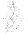
- Figure 1 shows means by which the contraceptives to be tested are conveyed to the testing apparatus on platens;
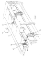
- Figure 2 is a similar view taken from the other end of the conveying apparatus; and
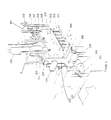
- Figure 3 is a view of the leak testing apparatus.
- The preferred embodiment of the invention is part of a machine or apparatus for making and testing bag-like means or contraceptive devices. The "method of and apparatus for making bag-like means" is described in more detail in the Applicant's co-pending U.K. Patent Application No. 9308453.1.
- The apparatus for making and testing bag-like means comprises a plurality of individual processing stations connected together in an assembly line arrangement. Each individual processing station performs a separate work task in the manufacture or testing of the bag-like means. The individual processing stations are fully automated and can be removed and substituted with an improved individual processing station as the technology for a particular work task changes.
- The preferred embodiment of the apparatus for making and testing bag-like means includes the following individual processing stations. A processing station for welding or joining a ring-like structure to the open end of a preformed bag-like means can be utilized to form the bag-like means. The formed bag-like means is then injected or transferred to a transporting means. Desirably, the transporting means is a platen. The platen supports and transports the formed bag-like means to a processing station for testing bag-like means. The tested bag-like means can be transported to an optional processing station for inserting an inner ring or other device into the bag-like means. Additionally, the bag-like means can be transported to an optional processing station for lubricating the bag-like means. A processing station for sorting bag-like means then separates rejected bag-like means from acceptable bag-like means. The acceptable bag-like means are then transported to a processing station for packaging the bag-like means.
- Figure 1 illustrates the
platens 141 and a conveying apparatus for moving theplatens 141 from the processing station for welding or joining a ring-like structure to the open end of a preformed bag-like means to the testing unit 8. For example, anindividual platen 141 waits for the formed bag-like means until twelve contraceptives are loaded intoopenings 140. Theplaten 141 is transported on aconveying system 142 by a motor means (not shown) and is guided byplaten shuffles platen 141 has aplaten check sensor 144 and aplaten home sensor 148. Theplaten check sensor 144 or theplaten home sensor 148 are received by a plurality ofrotary gates conveying system 142. The receipt of theplaten check sensor 144 or theplaten home sensor 148 by a rotary gate transmits a signal to a control means (not shown). The control means, such as a central computerized control system, can then actuate or terminate a function in the manufacture or testing of the bag-like means. A platen "full"sensor 150 and a platen "empty"sensor 151 are positioned on theconveying system 142 so as to identify theopenings 140 on aplaten 141 that are, respectively, holding a bag-like means or empty. - Figure 2 illustrates the conveying apparatus for moving the
platens 141 from the testing unit 8 to the processing station for sorting bag-like means in order to separate rejected bag-like means from acceptable bag-like means. This section of theconveying system 142, also, has a plurality ofplaten shuffles 152 and 153. The bag-like means are moved into or out of an opening 140 of aplaten 141 by a jet of pressurized air or a vacuum. For example, theconveying system 142 has a plurality ofvacuum generators 155 andair regulators 156 to create a vacuum. The suction of the vacuum is directed to affect the position of a bag-like means in theopenings 140 by a plurality oftransfer rods 157 andvacuum suckers 158. A similar unit utilizes pressurized air and a plurality ofair jets 159 to affect the position of a bag-like means in theopenings 140. - This invention is an apparatus for testing bag-like means or a "testing unit". This invention can be a processing station within the overall apparatus for making and testing bag-like means as described above.
- The bag-like means or "manufactured contraceptives" are transported via the
platens 141 to the testing unit 8. The testing unit 8 tests the bag-like means for leaks or holes. The testing unit 8 includes a first pressurizing means having a header with a plurality of gas inlets. The header is movably disposed for contacting the platen in a sealing relationship so that each gas inlet is in communication with the bag-like means in the platen. The apparatus can include a header having a sealing means around each gas inlet for sealing each of the bag-like means in the platen. The header includes a first valve means for selectively introducing a pressurizing medium, such as a gas, into the bag-like means. The header includes a second pressurizing means and a second valve means for selectively introducing a leak detecting medium, such as helium, into each bag-like means. The apparatus, desirably, includes an identification means with a means for controlling the second valve means in response to the identification of a bag-like means that exhibits a failure to hold the selected pressure. An evacuation means is, desirably, coupled to the header. - The apparatus of the invention further comprises a collection tray and means for positioning the collection tray in a sealing relationship with a platen in the testing unit. The collection tray collects any leak detection medium leaked from the bag-like means. A means for removing leak detection medium from the collection bag-like means is used to transfer the leak detection medium to the detection means. The apparatus includes a molecular sieve to separate the pressurizing medium, such as air contained in the collection tray, from the leak detection medium, such as helium. The separated leak detection medium passes to the detection means. The detection means can be a mass spectrometer for detecting the leak detecting medium. The apparatus, desirably, includes a means for purging the leak detecting medium from the bag-like means.
- Figure 3 illustrates the preferred processing station for testing bag-like means of this invention in more detail. The testing unit 8 of the preferred embodiment of the invention comprises a
frame 210. Theframe 210 carries side flaps 211, ahelium collection tray 212, twelvebag seals 213, twelvesolenoid valves 214, twelvepressure switches 215, ahelium regulator 216, areservoir pressure indicator 217,helium charge valves 218, vacuum extract valves 220, a helium reservoir221, ahelium intake valve 222, anair intake valve 223, amanifold pressure transducer 224, a station raise andlower switch 225, and a raise andlower flap 209. There is, also, provided a mass spectrometer or detector 226, an impinger or a molecular sieve 227, asample valve 228, apurge valve 230, and amanual valve 231. Anextraction shroud 240 and ashroud flow switch 241 are either raised from amovable platen 141 or lowered onto amovable platen 141 holding bag-like means. - The method for testing bag-like means at the processing station of this invention involves the following steps. The method begins when the
platen 141 is moved into the required position within the processing station for testing bag-like means. One or more of theopenings 140 in theplaten 141 hold a bag-like means. Theopenings 140, desirably, have a cylinder portion that rises above the surface of theplaten 141 and to from the aperture oropening 140. The diameter of the cylinder is less than the diameter of the ring that is welded to the open end of the bag-like means. The closed end of the bag-like means is placed in or through the aperture oropening 140 such that the ring about the open end of the bag-like means drops down the outside of the cylinder and rests on the surface of theplaten 141. The preferred embodiment of the testing unit, as described below, has twelveopenings 140 on eachplaten 141 so that twelve bag-like means can be tested simultaneously. The invention can be adapted to test any number of bag-like means. - The method first raises the side flaps 211 on each side of a positioned
platen 141 so that an enclosure is formed by the side flaps 211 and header around the bag-like means or contraceptive devices that are to be tested. The header or "sealing head" with twelvebag seals 213 then moves down into position on theplaten 141. Mounted to the header is a first pressurizing means. The header is movably disposed for contacting theplatens 141 in a sealing relationship so that each gas inlet is in communication with a bag-like means in theplaten 141. The header is, desirably, mounted above the conveyer for reciprocating movement with the transported platens. - The twelve
bag seals 213 comprise twelve individually gimbled heads (not shown). Each gimbled head forms a seal on each open end of each bag-like means held in theopenings 140 of theplaten 141. The individually gimbled head permits simultaneous testing of a plurality of bag-like means. If there is a defect in one bag-like means, it will not affect the testing of the other bag-like means. - The
air inlet valve 223 is then opened for a short interval of approximately one second to inflate the bag-like means. The air pressure in each bag-like means is then determined by the pressure switches 215. This pressure test identifies and registers with the control means, such as a central computerized control system, any individual bag-like means that has a gross leak. The air is then evacuated from the bag-like means and the pressure switches, via the control means, disable all the heads for the bag-like means that did not pass the gross leak test. The remaining heads are then charged by thehelium charge valves 218 so as to pass helium into the bag-like means. Helium is the preferred test gas for the preferred embodiment of the invention, but other test mediums or gases can be used with the invention. - The method then involves opening the
sample valve 228 to enable the air on the underside of theplaten 141 and any helium, which may have leaked through the bag-like means, to be pumped to the molecular sieve 227. The molecular sieve 227 enables any leaked helium to pass into the detector 226 while the main volume of air is pumped out of the molecular sieve 227 as exhaust. The detector 226, thus, is able to determine whether there is any leaked helium and, consequently, test the integrity of each bag-like means in theplaten 140. Another desirable embodiment of the invention permits leaked helium to be channeled to the detector for each individual bag-like means, however, this embodiment can slow the overall production process. - Once the detector 226 determines whether the platen is usable or not, the
sample valve 228 is closed and thepurge valve 230 is opened. This method step cleans thehelium collection tray 212 of any residual helium for the next test. Clean air is then pumped to the valves to reseat the bags and the sealing head is then raised and the side flaps 209 are lowered so that testedplaten 141 can be transported away and the next platen can be positioned for testing. Theplaten 141 is passed to the processing station for sorting bag-like means. - Thus the present invention provides a simple and effective method of and apparatus for testing bag-like means.
Claims (21)
Applications Claiming Priority (2)
| Application Number | Priority Date | Filing Date | Title |
|---|---|---|---|
| GB929216041A GB9216041D0 (en) | 1992-07-28 | 1992-07-28 | A method of and apparatus for testing bag-like means |
| GB9216041 | 1992-07-28 |
Publications (3)
| Publication Number | Publication Date |
|---|---|
| EP0581551A2 true EP0581551A2 (en) | 1994-02-02 |
| EP0581551A3 EP0581551A3 (en) | 1994-02-23 |
| EP0581551B1 EP0581551B1 (en) | 1997-05-21 |
Family
ID=10719446
Family Applications (1)
| Application Number | Title | Priority Date | Filing Date |
|---|---|---|---|
| EP93305861A Expired - Lifetime EP0581551B1 (en) | 1992-07-28 | 1993-07-26 | A method and apparatus for testing bag-like means |
Country Status (7)
| Country | Link |
|---|---|
| US (1) | US5524478A (en) |
| EP (1) | EP0581551B1 (en) |
| JP (1) | JP3299605B2 (en) |
| AT (1) | ATE153446T1 (en) |
| CA (1) | CA2101400A1 (en) |
| DE (1) | DE69310829T2 (en) |
| GB (1) | GB9216041D0 (en) |
Families Citing this family (31)
| Publication number | Priority date | Publication date | Assignee | Title |
|---|---|---|---|---|
| DE4426225B4 (en) * | 1994-07-23 | 2005-08-04 | Robert Griebel | Device for checking the porosity of thin rubber products |
| US6091058A (en) * | 1995-04-26 | 2000-07-18 | O.R. Solutions, Inc. | Thermal treatment system and method for maintaining integrity and ensuring sterility of surgical drapes used with surgical equipment |
| US5809788A (en) * | 1996-03-05 | 1998-09-22 | O.R. Solutions, Inc. | Surgical drape for use in forming and collecting surgical slush |
| US6003328A (en) * | 1996-03-05 | 1999-12-21 | O.R. Solutions, Inc. | Surgical drape having securing device for attachment to thermal treatment systems |
| US5816252A (en) * | 1997-04-29 | 1998-10-06 | O.R. Solutions, Inc. | Surgical drape leak detection method and apparatus |
| US6082184A (en) * | 1997-05-27 | 2000-07-04 | Martin Lehmann | Method for leak testing and leak testing apparatus |
| US6204669B1 (en) | 1997-07-02 | 2001-03-20 | Drexel University | Detection of defects in protective barriers |
| US7626017B2 (en) * | 1997-10-31 | 2009-12-01 | Pressure Biosciences, Inc. | Pressure-enhanced extraction and purification |
| US6164122A (en) * | 1999-04-21 | 2000-12-26 | Carter-Wallace, Inc. | System and method including multiple test chambers for automated testing for holes in prophylactic device |
| US6371121B1 (en) | 2000-05-17 | 2002-04-16 | O.R. Solutions, Inc. | Remote controlled thermal treatment system and method for controlling the system remotely to thermally treat sterile surgical liquid |
| US6860271B2 (en) * | 2000-05-17 | 2005-03-01 | O.R. Solutions, Inc. | Thermal treatment system and method for controlling the system to thermally treat sterile surgical liquid |
| US7854230B2 (en) * | 2001-10-22 | 2010-12-21 | O.R. Solutions, Inc. | Heated medical instrument stand with surgical drape and method of detecting fluid and leaks in the stand tray |
| US7347210B2 (en) * | 2001-10-22 | 2008-03-25 | O.R. Solutions, Inc. | Surgical drape with conductor and method of detecting fluid and leaks in thermal treatment system Basins |
| US7959860B2 (en) * | 2001-10-22 | 2011-06-14 | Faries Jr Durward I | System and method of detecting fluid and leaks in thermal treatment system basins |
| US6810881B2 (en) * | 2001-10-22 | 2004-11-02 | O.R. Solutions, Inc. | Medical solution thermal treatment system and method of controlling system operation in accordance with detection of solution and leaks in surgical drape containers |
| US7418966B2 (en) | 2001-10-22 | 2008-09-02 | O. R. Solutions, Inc. | Surgical drape and method of detecting fluid and leaks in thermal treatment system basins |
| US20050247169A1 (en) * | 2003-11-26 | 2005-11-10 | Faries Durward I Jr | Fastening system and method of fastening objects with enhanced security |
| US7350373B1 (en) | 2003-12-23 | 2008-04-01 | O.R. Solutions, Inc. | Surgical disk drape and method of dislodging surgical slush within thermal treatment system basins |
| US7671302B1 (en) * | 2004-03-23 | 2010-03-02 | O. R. Solutions, Inc. | Thermal treatment system instrument rack and method of selectively thermally treating medical instrument portions |
| US7728262B1 (en) * | 2004-03-23 | 2010-06-01 | O.R. Solutions, Inc. | Thermal treatment system instrument rack and method of selectively thermally treating medical instrument portions |
| DE602004021645D1 (en) * | 2004-09-17 | 2009-07-30 | Everhard Vissers | DEVICE FOR TESTING PACKAGING MATERIAL |
| US8148666B2 (en) * | 2005-09-01 | 2012-04-03 | Patented Medical Solutions, Llc | Method and apparatus for protecting sterile drapes in surgical thermal treatment systems |
| KR100785761B1 (en) * | 2005-11-16 | 2007-12-18 | 정경수 | Traffic gate for parking lot |
| US8789534B2 (en) * | 2008-04-09 | 2014-07-29 | Patented Medical Solutions, Llc | Method and apparatus for warming medical solutions in a thermal treatment system employing a removable basin |
| WO2012029049A2 (en) | 2010-09-02 | 2012-03-08 | Ecolab Usa Inc. | Selective thermal treatment of medical instrument portions with thermal treatment system instrument holder |
| WO2013106324A1 (en) | 2012-01-09 | 2013-07-18 | Wurst James | Three wheel lean-steer skateboard |
| EP3098585B1 (en) | 2015-05-28 | 2018-02-28 | Airbus Operations, S.L. | Inspection methods and systems for detecting leaks in vacuum bag assemblies |
| CN106289677A (en) * | 2016-08-09 | 2017-01-04 | 桐城运城制版有限公司 | A kind of device of quick detection sealing performance of soft packing bag |
| CN107560808B (en) * | 2017-09-29 | 2023-11-21 | 浙江鸿昌机械有限公司 | Condom feeding mechanism of automatic electric inspection machine for condoms |
| CN108043743B (en) * | 2017-10-30 | 2020-05-15 | 广州市山本机械有限公司 | Condom sorting system |
| WO2022168066A1 (en) * | 2021-02-08 | 2022-08-11 | Intex Industries Xiamen Co. Ltd. | Gas leakage testing device for inflatable product |
Citations (3)
| Publication number | Priority date | Publication date | Assignee | Title |
|---|---|---|---|---|
| US3708949A (en) * | 1969-02-04 | 1973-01-09 | Safeway Stores | Method and apparatus for detection of leaks in seals of packages |
| GB2234596A (en) * | 1989-07-28 | 1991-02-06 | Lin Chyi Shyan | Leak-detecting means for rubber product |
| US5129256A (en) * | 1991-03-27 | 1992-07-14 | Lrc Products, Ltd. | Method and apparatus for leak testing of condoms by pressure differential |
Family Cites Families (12)
| Publication number | Priority date | Publication date | Assignee | Title |
|---|---|---|---|---|
| US2383936A (en) * | 1943-01-13 | 1945-09-04 | Owens Illinois Glass Co | Vacuum testing apparatus |
| US2800788A (en) * | 1956-05-14 | 1957-07-30 | Willard H Smith | Glove testing apparatus |
| US3374887A (en) * | 1966-03-11 | 1968-03-26 | Brockway Glass Co Inc | Automatic inspection means for containers |
| US3785195A (en) * | 1972-08-07 | 1974-01-15 | Yamamura Glass Co Ltd | Apparatus for testing pressure resistance of bottles |
| US4010877A (en) * | 1975-06-09 | 1977-03-08 | Parke, Davis & Company | Work fixture and folding method |
| US3992766A (en) * | 1975-08-26 | 1976-11-23 | Youngs Rubber Corporation | Apparatus for processing elastic articles |
| SU1167465A1 (en) * | 1983-08-22 | 1985-07-15 | Lev M Veryatin | Automatic device for checking hermetic sealing of hollow articles |
| US4733555A (en) * | 1987-04-13 | 1988-03-29 | Franks Stephen H | Pressure entry and test system |
| US5073482A (en) * | 1988-06-21 | 1991-12-17 | Epitope, Inc. | Elastic barrier permeability testing device and method of use |
| US5049168A (en) * | 1988-09-12 | 1991-09-17 | Philip Danielson | Helium leak detection method and system |
| US5138871A (en) * | 1990-04-06 | 1992-08-18 | The United States Of America As Represented By The Department Of Health And Human Services | Method and apparatus for testing the permeability of prophylactics |
| US5097697A (en) * | 1990-06-06 | 1992-03-24 | Ansell Incorporated | Method and apparatus for airburst testing condoms and the like |
-
1992
- 1992-07-28 GB GB929216041A patent/GB9216041D0/en active Pending
-
1993
- 1993-07-26 DE DE69310829T patent/DE69310829T2/en not_active Expired - Fee Related
- 1993-07-26 EP EP93305861A patent/EP0581551B1/en not_active Expired - Lifetime
- 1993-07-26 AT AT93305861T patent/ATE153446T1/en not_active IP Right Cessation
- 1993-07-27 CA CA002101400A patent/CA2101400A1/en not_active Abandoned
- 1993-07-28 JP JP20575493A patent/JP3299605B2/en not_active Expired - Fee Related
-
1995
- 1995-04-05 US US08/417,472 patent/US5524478A/en not_active Expired - Fee Related
Patent Citations (3)
| Publication number | Priority date | Publication date | Assignee | Title |
|---|---|---|---|---|
| US3708949A (en) * | 1969-02-04 | 1973-01-09 | Safeway Stores | Method and apparatus for detection of leaks in seals of packages |
| GB2234596A (en) * | 1989-07-28 | 1991-02-06 | Lin Chyi Shyan | Leak-detecting means for rubber product |
| US5129256A (en) * | 1991-03-27 | 1992-07-14 | Lrc Products, Ltd. | Method and apparatus for leak testing of condoms by pressure differential |
Also Published As
| Publication number | Publication date |
|---|---|
| EP0581551B1 (en) | 1997-05-21 |
| JP3299605B2 (en) | 2002-07-08 |
| JPH0727654A (en) | 1995-01-31 |
| EP0581551A3 (en) | 1994-02-23 |
| GB9216041D0 (en) | 1992-09-09 |
| DE69310829T2 (en) | 1997-09-11 |
| US5524478A (en) | 1996-06-11 |
| DE69310829D1 (en) | 1997-06-26 |
| ATE153446T1 (en) | 1997-06-15 |
| CA2101400A1 (en) | 1994-01-29 |
Similar Documents
| Publication | Publication Date | Title |
|---|---|---|
| EP0581551B1 (en) | A method and apparatus for testing bag-like means | |
| US4184362A (en) | Bottle leak tester | |
| US5850036A (en) | Apparatus for leak testing vehicle wheels | |
| US4813268A (en) | Leakage detection apparatus for drum wheels and method therefore | |
| US5668307A (en) | Apparatus for testing can ends for leaks | |
| JP3376250B2 (en) | Apparatus and method for inspecting leakage of hollow member | |
| JPH06320265A (en) | Device for fitting final stopper into covering pipe containing nuclear fuel, welding and inspecting welded part according to complete automation procedure | |
| US3499314A (en) | Apparatus for testing covers | |
| US4099404A (en) | Automatic air leak testing apparatus and method for batteries | |
| CN104492733B (en) | Automatic filter leakage detection device and automatic leakage detection method | |
| JP3920426B2 (en) | Leak inspection device | |
| US6164122A (en) | System and method including multiple test chambers for automated testing for holes in prophylactic device | |
| US3751989A (en) | Fixture and system for treating test pieces on a rapid cycle leak detection apparatus | |
| WO1999005496A1 (en) | Automated testing apparatus and methods, especially for flexible walled containers | |
| US4010840A (en) | Automatic air leak testing apparatus for multiple chambered containers | |
| CN215466857U (en) | Air bag belt cleaning device | |
| CN210906988U (en) | Take suction nozzle flexible packaging bag's gas tightness detection device | |
| CN113945324A (en) | Flexible glove sealing performance detection device | |
| CN114486105A (en) | Multi-station battery cover plate helium detection system | |
| CN110281536A (en) | Check valve assembles detection machine | |
| CN217191039U (en) | Detection unit and lithium battery automatic detection system | |
| US5167141A (en) | Seal withdrawal and testing device | |
| JP3610889B2 (en) | Hermetically sealed work storage unit, gas leak inspection apparatus, and gas leak inspection method | |
| CN214407926U (en) | Automatic leak detection conveying line for dialyzer production | |
| JP4248966B2 (en) | Cup leak inspection device |
Legal Events
| Date | Code | Title | Description |
|---|---|---|---|
| PUAI | Public reference made under article 153(3) epc to a published international application that has entered the european phase |
Free format text: ORIGINAL CODE: 0009012 |
|
| PUAL | Search report despatched |
Free format text: ORIGINAL CODE: 0009013 |
|
| AK | Designated contracting states |
Kind code of ref document: A2 Designated state(s): AT BE CH DE DK ES FR GB GR IE IT LI LU MC NL PT SE |
|
| AK | Designated contracting states |
Kind code of ref document: A3 Designated state(s): AT BE CH DE DK ES FR GB GR IE IT LI LU MC NL PT SE |
|
| 17P | Request for examination filed |
Effective date: 19940823 |
|
| GRAG | Despatch of communication of intention to grant |
Free format text: ORIGINAL CODE: EPIDOS AGRA |
|
| 17Q | First examination report despatched |
Effective date: 19960412 |
|
| GRAH | Despatch of communication of intention to grant a patent |
Free format text: ORIGINAL CODE: EPIDOS IGRA |
|
| GRAH | Despatch of communication of intention to grant a patent |
Free format text: ORIGINAL CODE: EPIDOS IGRA |
|
| GRAH | Despatch of communication of intention to grant a patent |
Free format text: ORIGINAL CODE: EPIDOS IGRA |
|
| GRAH | Despatch of communication of intention to grant a patent |
Free format text: ORIGINAL CODE: EPIDOS IGRA |
|
| GRAA | (expected) grant |
Free format text: ORIGINAL CODE: 0009210 |
|
| AK | Designated contracting states |
Kind code of ref document: B1 Designated state(s): AT BE CH DE DK ES FR GB GR IE IT LI LU MC NL PT SE |
|
| PG25 | Lapsed in a contracting state [announced via postgrant information from national office to epo] |
Ref country code: NL Free format text: LAPSE BECAUSE OF FAILURE TO SUBMIT A TRANSLATION OF THE DESCRIPTION OR TO PAY THE FEE WITHIN THE PRESCRIBED TIME-LIMIT Effective date: 19970521 Ref country code: LI Effective date: 19970521 Ref country code: GR Free format text: LAPSE BECAUSE OF FAILURE TO SUBMIT A TRANSLATION OF THE DESCRIPTION OR TO PAY THE FEE WITHIN THE PRESCRIBED TIME-LIMIT Effective date: 19970521 Ref country code: ES Free format text: THE PATENT HAS BEEN ANNULLED BY A DECISION OF A NATIONAL AUTHORITY Effective date: 19970521 Ref country code: DK Effective date: 19970521 Ref country code: CH Effective date: 19970521 Ref country code: BE Effective date: 19970521 Ref country code: AT Effective date: 19970521 |
|
| REF | Corresponds to: |
Ref document number: 153446 Country of ref document: AT Date of ref document: 19970615 Kind code of ref document: T |
|
| REG | Reference to a national code |
Ref country code: CH Ref legal event code: EP |
|
| REF | Corresponds to: |
Ref document number: 69310829 Country of ref document: DE Date of ref document: 19970626 |
|
| PG25 | Lapsed in a contracting state [announced via postgrant information from national office to epo] |
Ref country code: LU Free format text: LAPSE BECAUSE OF NON-PAYMENT OF DUE FEES Effective date: 19970726 Ref country code: IE Free format text: LAPSE BECAUSE OF NON-PAYMENT OF DUE FEES Effective date: 19970726 |
|
| ET | Fr: translation filed | ||
| PG25 | Lapsed in a contracting state [announced via postgrant information from national office to epo] |
Ref country code: SE Effective date: 19970821 Ref country code: PT Effective date: 19970821 |
|
| NLV1 | Nl: lapsed or annulled due to failure to fulfill the requirements of art. 29p and 29m of the patents act | ||
| REG | Reference to a national code |
Ref country code: CH Ref legal event code: PL |
|
| PG25 | Lapsed in a contracting state [announced via postgrant information from national office to epo] |
Ref country code: MC Free format text: LAPSE BECAUSE OF NON-PAYMENT OF DUE FEES Effective date: 19980131 |
|
| PLBE | No opposition filed within time limit |
Free format text: ORIGINAL CODE: 0009261 |
|
| STAA | Information on the status of an ep patent application or granted ep patent |
Free format text: STATUS: NO OPPOSITION FILED WITHIN TIME LIMIT |
|
| 26N | No opposition filed | ||
| PGFP | Annual fee paid to national office [announced via postgrant information from national office to epo] |
Ref country code: GB Payment date: 19980623 Year of fee payment: 6 |
|
| PGFP | Annual fee paid to national office [announced via postgrant information from national office to epo] |
Ref country code: FR Payment date: 19980707 Year of fee payment: 6 |
|
| PGFP | Annual fee paid to national office [announced via postgrant information from national office to epo] |
Ref country code: DE Payment date: 19980728 Year of fee payment: 6 |
|
| PG25 | Lapsed in a contracting state [announced via postgrant information from national office to epo] |
Ref country code: GB Free format text: LAPSE BECAUSE OF NON-PAYMENT OF DUE FEES Effective date: 19990726 |
|
| PG25 | Lapsed in a contracting state [announced via postgrant information from national office to epo] |
Ref country code: FR Free format text: THE PATENT HAS BEEN ANNULLED BY A DECISION OF A NATIONAL AUTHORITY Effective date: 19990731 |
|
| REG | Reference to a national code |
Ref country code: GB Ref legal event code: 732E |
|
| GBPC | Gb: european patent ceased through non-payment of renewal fee |
Effective date: 19990726 |
|
| PG25 | Lapsed in a contracting state [announced via postgrant information from national office to epo] |
Ref country code: DE Free format text: LAPSE BECAUSE OF NON-PAYMENT OF DUE FEES Effective date: 20000503 |
|
| REG | Reference to a national code |
Ref country code: FR Ref legal event code: ST |
|
| REG | Reference to a national code |
Ref country code: FR Ref legal event code: GC |
|
| PG25 | Lapsed in a contracting state [announced via postgrant information from national office to epo] |
Ref country code: IT Free format text: LAPSE BECAUSE OF NON-PAYMENT OF DUE FEES;WARNING: LAPSES OF ITALIAN PATENTS WITH EFFECTIVE DATE BEFORE 2007 MAY HAVE OCCURRED AT ANY TIME BEFORE 2007. THE CORRECT EFFECTIVE DATE MAY BE DIFFERENT FROM THE ONE RECORDED. Effective date: 20050726 |