EP0583006A2 - IC card with hierarchical file structure - Google Patents
IC card with hierarchical file structure Download PDFInfo
- Publication number
- EP0583006A2 EP0583006A2 EP93112836A EP93112836A EP0583006A2 EP 0583006 A2 EP0583006 A2 EP 0583006A2 EP 93112836 A EP93112836 A EP 93112836A EP 93112836 A EP93112836 A EP 93112836A EP 0583006 A2 EP0583006 A2 EP 0583006A2
- Authority
- EP
- European Patent Office
- Prior art keywords
- file
- files
- key
- level
- directory
- Prior art date
- Legal status (The legal status is an assumption and is not a legal conclusion. Google has not performed a legal analysis and makes no representation as to the accuracy of the status listed.)
- Granted
Links
Images


Classifications
-
- G—PHYSICS
- G06—COMPUTING; CALCULATING OR COUNTING
- G06K—GRAPHICAL DATA READING; PRESENTATION OF DATA; RECORD CARRIERS; HANDLING RECORD CARRIERS
- G06K19/00—Record carriers for use with machines and with at least a part designed to carry digital markings
- G06K19/06—Record carriers for use with machines and with at least a part designed to carry digital markings characterised by the kind of the digital marking, e.g. shape, nature, code
- G06K19/067—Record carriers with conductive marks, printed circuits or semiconductor circuit elements, e.g. credit or identity cards also with resonating or responding marks without active components
- G06K19/07—Record carriers with conductive marks, printed circuits or semiconductor circuit elements, e.g. credit or identity cards also with resonating or responding marks without active components with integrated circuit chips
- G06K19/073—Special arrangements for circuits, e.g. for protecting identification code in memory
-
- G—PHYSICS
- G07—CHECKING-DEVICES
- G07F—COIN-FREED OR LIKE APPARATUS
- G07F7/00—Mechanisms actuated by objects other than coins to free or to actuate vending, hiring, coin or paper currency dispensing or refunding apparatus
- G07F7/08—Mechanisms actuated by objects other than coins to free or to actuate vending, hiring, coin or paper currency dispensing or refunding apparatus by coded identity card or credit card or other personal identification means
- G07F7/10—Mechanisms actuated by objects other than coins to free or to actuate vending, hiring, coin or paper currency dispensing or refunding apparatus by coded identity card or credit card or other personal identification means together with a coded signal, e.g. in the form of personal identification information, like personal identification number [PIN] or biometric data
- G07F7/1008—Active credit-cards provided with means to personalise their use, e.g. with PIN-introduction/comparison system
-
- G—PHYSICS
- G06—COMPUTING; CALCULATING OR COUNTING
- G06Q—INFORMATION AND COMMUNICATION TECHNOLOGY [ICT] SPECIALLY ADAPTED FOR ADMINISTRATIVE, COMMERCIAL, FINANCIAL, MANAGERIAL OR SUPERVISORY PURPOSES; SYSTEMS OR METHODS SPECIALLY ADAPTED FOR ADMINISTRATIVE, COMMERCIAL, FINANCIAL, MANAGERIAL OR SUPERVISORY PURPOSES, NOT OTHERWISE PROVIDED FOR
- G06Q20/00—Payment architectures, schemes or protocols
- G06Q20/30—Payment architectures, schemes or protocols characterised by the use of specific devices or networks
- G06Q20/34—Payment architectures, schemes or protocols characterised by the use of specific devices or networks using cards, e.g. integrated circuit [IC] cards or magnetic cards
- G06Q20/341—Active cards, i.e. cards including their own processing means, e.g. including an IC or chip
-
- G—PHYSICS
- G06—COMPUTING; CALCULATING OR COUNTING
- G06Q—INFORMATION AND COMMUNICATION TECHNOLOGY [ICT] SPECIALLY ADAPTED FOR ADMINISTRATIVE, COMMERCIAL, FINANCIAL, MANAGERIAL OR SUPERVISORY PURPOSES; SYSTEMS OR METHODS SPECIALLY ADAPTED FOR ADMINISTRATIVE, COMMERCIAL, FINANCIAL, MANAGERIAL OR SUPERVISORY PURPOSES, NOT OTHERWISE PROVIDED FOR
- G06Q20/00—Payment architectures, schemes or protocols
- G06Q20/30—Payment architectures, schemes or protocols characterised by the use of specific devices or networks
- G06Q20/34—Payment architectures, schemes or protocols characterised by the use of specific devices or networks using cards, e.g. integrated circuit [IC] cards or magnetic cards
- G06Q20/357—Cards having a plurality of specified features
- G06Q20/3576—Multiple memory zones on card
- G06Q20/35765—Access rights to memory zones
Definitions
- the present invention relates to an integrated circuit card for controlling, using key referencing data, access to plural files contained therein.
- IC cards Conventional integrated circuit cards
- the internal memory 200 of the IC card contains a single parent file 201 located in the first level, and plural child files 202, 203 located in the second level.
- the child files 202, 203 may be used by different applications.
- the parent file 201 is used by plural applications, and stores common data 204 such as the cardholder's name, address and telephone number, and a global key 205 that is not dependent upon the application.
- the child files 202, 203 store application-specific data 206, 208 and a local key 207, 209.
- the global key 205 and local keys 207, 209 are used to control access to the parent 201 and child files 202, 203, and access to the common data 204 and application-specific data 206, 208 is only permitted after the required key has been correctly verified.
- the conventional IC card file structure has only two levels, and access control is therefore also limited to these two levels. More specifically, if the global key 205 is correctly verified, the common data 204 as well as the application-specific data 206, 208 can be accessed, and if only a local key 207, 209 is verified, the specific data of the file protected by the verified local key can be accessed.
- This file structure presents two problems. First, a file structure having three or more levels cannot be used because the access control method is limited to a two-level file structure. For example, if a grandchild file (not shown in the figures) belonging to one child file 202 is created, the local key 207 may be required to function as a global key for the dependent grandchild files, but this is not possible.
- an object of the present invention is to resolve these problems by providing an IC card compatible with a hierarchical file structure and capable of maintaining the confidentiality of files from the card issuer.
- an IC card comprises a processing controller, non-volatile memory having plural files in a hierarchical structure and an access conditions controller related to the level number in the hierarchical structure, and volatile memory having plural key information fields corresponding to the level numbers.
- Fig. 1 is a block diagram of the first embodiment of this IC card 1 comprising a processing controller 2, RAM 3, and non-volatile memory 4.
- the processing controller 2 has an input/output control 5 and a command processor 6.
- the command processor 6 has an access control 7 which has a first comparator 8 for comparing the input key data and registered key data, and a second comparator 9 for comparing 8-bit data formed in RAM 3 and 8-bit data stored in memory 4, as will be described in detail later.
- the processing controller 2 may be formed in hardware using a CPU, ROM, input/output control, or other device, but is represented in Fig. 1 as a processing block achieved by means of a software program stored in a ROM device. A detail of this processing control 2 is described below.
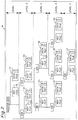
- the non-volatile memory 4 stores plural files as shown in Fig. 2 in a logical file structure with five levels.
- Level 1 has a master directory, one key file 10 and one data file 11.
- Each of levels 2-5 has one or more directories, key files and data files.
- level 2 has two directories, two key files and two data files 21 and 22.
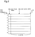
- key file 20 for the level 2 has eight key boxes, and each key box has a key flag area 20a in which a key flag indicating whether or not key data is stored, and a key data area 20b in which key data are stored.
- the key file can store, at the maximum, eight different keys.
- Such keys may be registered by the holder (user) of the IC card, and/or by the distributer (bank, telephone company, etc.) of the IC card.
- the other key files have the same structure as the key file 20.
- Each data file and key file are managed by the directory 61, which has as shown in Fig.6, a current level indicator 91 for indicating the current directory level and a parent pointer 92 for indicating the parent directory.
- each data file such as data file 32 at the third hierarchical level 3, comprises a data area for storing data.
- Each data file further has an access condition controller (ACC) 80 which comprises an access key box designation table 81 and a logic conditions area 82.
- the logic conditions area 82 further comprises a horizontal matching condition settings area 83 and a vertical matching condition settings table 84.
- the values set in the access conditions controller 80 differ for each data file.
- the access key box designation table 81 is usually set by the card distributer and designates the key box numbers at which stored key data requires verification. In the example, it is indicated that the key data from key boxes 1 and/or 2 is (are) required to be verified.
- the horizontal matching condition settings area 83 is set to "1", but when at least one of the key data from key boxes 1 and 2 is sufficient, the horizontal matching condition settings area 83 is set to "0". In other words, horizontal matching condition settings area 83 sets logical AND condition or logical OR condition for the designated key box numbers.
- the vertical matching condition settings table 84 is also usually set by the card distributer and sets the levels from which the key files are collected and can be used for checking.
- the data stored in vertical matching condition settings table 84 is used for controlling switches SW1-SW5 inserted in the lines connected to OR gate 70 in Fig. 4, as will be explained later. In the example, it is indicated that the key files from levels 1, 2 and 3 can be used for checking.
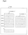
- the RAM 3 contains a key verification indication table 71, which is divided into five fields corresponding to the five levels of the hierarchical structure shown in Fig. 2, and each field comprises eight bits corresponding to eight key box numbers (where bit 1 is equivalent to key box number 1). For example, if the key data in key box 1 in level 1 is verified, indicator at right top corner in the key verification indication table 71 is set to "1", as shown in Fig. 4. Also, if the key data in key box 2 in level 3 is verified, the indicator at corresponding area in the key verification indication table 71 is set to "1". The indicator "1" in table 71 means that the corresponding key has been verified.
- the RAM 3 further has a logical OR table 72 which takes logical OR along each column in table 71 by an OR gate 70 provided in association with RAM 3.
- OR gate 70 provided in association with RAM 3.
- left two bits are set “1” and the remaining bits are set "0".
- Switches SW1-SW5 are connected to five input lines connected to OR gate 70, respectively. Switches SW1-SW5 turn ON when corresponding bit in vertical matching condition settings table 84 is "1".
- switches SW1-SW3 are ON and switches SW4 and SW5 are OFF.
- OR gate it is possible to use AND gate at 70.
- data file 32 such as for bank cashing
- the user inserts the IC card in a cash dispenser (not shown).
- the cash dispenser automatically sends an identification key data, together with data indicating key file 10 in level 1 and data indicating key box 1, through input/output 5 to command processor 6.
- the access control 7 reads, in accordance with the received data of level 1 and key box 1, the key data stored in the key box 1 of the key file 10 in level 1, and compares in the first comparator 8 the received identification key data with the key data stored in the key box 1 of the key file 10 in level 1. If these two keys match, the first comparator 8 generates "1" and is stored RAM 3, particularly in table 71 at area corresponding to key box 1 in level 1.
- the user selects a "cashing" button on the cash dispenser, and inputs his own secret key data through a key board.
- the access control 7 is informed that the key data for matching is stored in key box 2 of key file 30 in level 3.
- the first comparator 8 the secret key data inputted by the user is compared with the key data stored in key box 2 of key file 30 in level 3. If these two keys match, the first comparator 8 again generates "1" which is stored in RAM 3, particularly in table 71 at area corresponding to key box 2 in level 3.
- OR gate 70 takes logic OR in each column in table 71, i.e., among the same number key boxes, and stores the result in table 72.
- the 8-bit data stored in table 72 is applied to second comparator 9, which is an 8-bit comparator, for comparing 8-bit data stored in access key box designation table 81.
- the file selection command is input to the input/output 5 and interpreted by the command processor 6.
- the command processor 6 searches for the file name specified by the external device (e.g, cash dispenser), and when successful transfers control to the access controller 7.
- an access conditions controller is also provided for controlling write access.
- An access rights controller is also provided for each function, including key registration and updating.
- access can be controlled in various ways.
- a typical example is described below.
- a card issuer key (key number 1) and a cardholder personal identification number (PIN) key (key number 2) both stored at key file 10 (level 1)
- PIN personal identification number
- terminal key (key number 1) stored at key file 30 used by the application using the data file 32 on the terminal.
- the horizontal access condition is set to the logical product (set in the horizontal settings area) of the key number 1 key and the key number 2 key (set in access key box designation table 81) for the read function of the data area.
- those parts of the vertical matching condition settings table 84 corresponding to levels 1 and 3 are set to "1.”
- level 3 is set to "1" in the vertical matching condition settings table 84. Private files that cannot be accessed by the card issuer can thus be created in the IC card.
- the horizontal access condition by horizontal matching condition settings area 83 is set to "0" for taking the logical OR of key numbers 1 and 2 for the PIN update function.
- the structure of the vertical matching condition settings table 84 in this embodiment has been described as specifying the level number used in the logical OR calculations, but shall not be so limited, any method enabling identification of the method of calculating the logical OR can be used.
- keys on the higher levels can also function as global keys for lower level files.
- a typical example of this is the PIN. Users may often want to use the same PIN for plural applications.
- the one PIN is registered at the highest level of the file structure branch in which the plural files are stored rather than storing the PIN with each file.
- the single PIN can thus be used to access all files lower in the hierarchy.
- This global key concept is not limited to PIN applications, however, and can be applied to any desired key. Rather than enabling only the key registered in the highest level of the file structure to function as a global key, greater utility can be achieved by enabling any key registered at level n to function as a global key for files stored at all levels below level n in the hierarchy.
- the key information for files on a common branch in the file structure must be retained when two or more files are selected.
- the key information up to level 2 is retained because the branches on which file 32 and file 41 are located start from the same level 2. Because the key file 30 for data file 32 (level 3) has no relationship to file 41, however, access to file 41 using the key file 30 must be prohibited for security. The key information for level 3 is therefore destroyed.
- the key verification indication table 71 shown in Fig. 4 comprises fields for each level as described above, and each file directory contains the information shown in Fig. 6 (in addition to file address and other information). Only that information required for this description is shown in Fig. 6.
- each directory retains the same information shown in Fig. 6.
- the current directory 91 is the number of the current level on which the file is located; for file 32 this is "3.”
- the parent pointer 92 indicates (e.g., the position of the directory of the parent file) the parent file of this file.
- the directory of file 32 stores "the directory of file 22" as a parent pointer 92. Because there is no parent file for file 11, such information is written to the file 11 parent file pointer.
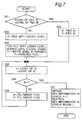
- Fig. 7 is a flow chart for part of the access controller 7 shown in Fig. 1, specifically for processing the key information in the file selection command process. Note that in the following description the previously selected file is file A (data file 32), and the newly selected file is file B (data file 41).
- the level numbers of data files A (32) and B (42) are compared. If they are the same, X is registered with the file number of file A and Y with the file number of file B, and the process advances to (2) below.
- X is registered with the file number of a file with a higher level number (in this case, X ⁇ 32).
- the file tree structure is searched upward until the level equal to the level number of X is reached, and the reached file number is registered in Y (in this case, Y ⁇ 31). Then, the process advances to (2) below.
- the common level number of the files registered in X and Y is detected and registered in L (in this case, L ⁇ 3).
- it is detected whether or not X Y .
- the process advances to Step 308 at which X and Y are registered with the parent file number of the current indicated file.
- step 307 the key information from level 1 to level L is retained, and the key information for levels below L is destroyed to terminate the loop.
- Loop (2) is thus repeated until X and Y are the same. Because there is only one root file in an IC card as shown in Fig. 2, the loop will always end with L ⁇ 1.
- the level numbers of each file shown in Fig. 6 are used to determine the level numbers of X and Y, and the parent pointer is used to determine the parent file of each file.
- this file structure has so far been limited to a file system in which only one file can be opened and in use at one time.
- the file system has a limit of one open file at a time and it becomes necessary to access another file while working with the first file, the first file must be closed, the file to be accessed selected, and the required key verified before processing continues. Repeating this sequence of operations becomes increasingly inefficient when two files must be alternately accessed. Being able to simultaneously open and access more than one file at a time would therefore be extremely convenient and helpful.
- Whether the key information is held or destroyed depends on the level structure of the file and not on the channel. In other words, if the previously selected files on channels A and B are files P and Q, and the newly selected file on channel A is file R, the sum set of the key information common to the common branch of files P and R and the key information common to the common branch of files Q and R is retained.
- file 41 in Fig. 2 is file P
- file 51 is file Q
- file 43 is file R.
- the key information to level 2 is retained based on the relationship between files 41 and 43.
- the key information to level 3 is also retained based on the relationship between files 51 and 43. Because the former key information is also contained within the latter key information set, the key information for channel A contains the key information for the latter, specifically for level 3 common to files 51 and 43.
- Fig. 9 is a flow chart for part of the access controller 7 shown in Fig. 1, specifically for processing the channel A key information.
- the key information for channel A is held or destroyed based on the relationship between files P and R. (The specific method conforms to the process described above for a file system enabling only one open file at a time.)
- the level numbers 1 - L for which the key information is to be retained are obtained from the relationship between files Q and R. (The specific method conforms to the process described above for a file system enabling only one open file at a time.)
- Copying the key information for level 2 is redundant in step 313 above because level 2 is common to all three files 41, 51, and 43.
- the present method is still extremely effective, however, considering that there are any number of ways different files can be selected, and is applicable to all possible cases while remaining extremely simple. It is difficult to determine the branches common to plural files for each of the many different possible file selections in order to eliminate this redundancy, and the present method is thus more effective.
- Another benefit of this method is expandability. For example, when the number of simultaneously usable files is increased to three or more (A, B, C, — ), it is sufficient to simply continue looping through step 313.
- the present method is therefore superior in terms of program size, processing speed, and expandability.
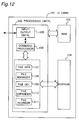
- an IC card 101 comprises a process controller 102, which uses the RAM 103 as a process buffer, an input/output means 105 for exchanging data with an external device, a command processor 106, a file generator 107 for creating new files, a file manager 108, a file deleting means 109, a file expander 110 for increasing the capacity of a file selected by command, and a file reordering means 111 for compactly reordering the plural files stored in the EEPROM 104.
- a process controller 102 which uses the RAM 103 as a process buffer, an input/output means 105 for exchanging data with an external device, a command processor 106, a file generator 107 for creating new files, a file manager 108, a file deleting means 109, a file expander 110 for increasing the capacity of a file selected by command, and a file reordering means 111 for compactly reordering the plural files stored in the EEPROM 104.
- the command processor 106 analyzes and processes the commands received through the I/O means 105, and generates the response to the received commands.
- the command processor 106 also activates the file generator 107, file manager 108, file deleting means 109, file expander 110, and file reordering means 111.
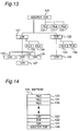
- FIG. 13 An example of the file directory in this IC card 101 is shown in Fig. 13.
- This file system comprises a master directory 120 and two dependent directories 121, 122.
- Directory 121 in turn has plural dependent directories 123, 124, 125, directory 122 has a dependent directory 126, and directory 124 has a dependent directory 127.
- the file structure of this IC card 101 comprises a single master directory 120 with plural dependent directories arrayed in a hierarchical structure, and each single directory can manage plural attached files (not shown in the figure) and directories.
- the following description refers to "parent" directories and the dependent directories of the parent directory as "child" directories.
- the data structure of the file memory on IC card 101 is shown in Fig. 14 for this embodiment.
- Directories are stored from highest to lowest address, and files are stored from lowest to highest address in the EEPROM 104.
- the "user area” refers to the area storing the directories and files. Deleting a file from this structure creates unused areas in the EEPROM 104, and is inefficient. This makes it necessary to optimize the storage area by reordering the files and directories.
- the data structure of the master directory, dependent directories, and files is described first.
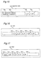
- the structure of the master directory 120 of the IC card 101 is shown in Fig. 15.
- the DF write pointer 140 is the address of the last created directory (directory 123 in Fig. 14)
- the EF write pointer 141 is the address of the next file created (the next address after the last file address (file 132 in Fig. 14))
- C_DF 142 is the address of the first created child directory (directory 121 in Fig. 14) managed by the master directory 120
- C_EF 143 is the address of the first created file (file 130 in Fig. 14) managed by the master directory 120.
- a value of 0000 is stored to C_DF 142 and C_EF 143 if the corresponding directory or file does not exist.
- P_DF 150 is the starting address of the parent directory of the directory (the master directory 120 in Fig. 13).
- N_DF 151 is the starting address of the directory created after directory 121 (i.e., directory 122 in Fig. 13) at the root of the parent directory managing that directory 121,
- B_DF 152 is the starting address of the directory created before directory 121 (i.e., does not exist in Fig. 14) at the root of the parent directory managing that directory 121,
- C_DF 153 is the address of the first child directory (directory 123 in Figs.
- C_EF 154 is the address of the first file (not shown) managed by the directory 121.
- a value of 0000 is stored to N_DF 151, B_DF 152, C_DF 153, and C_EF 154 if the corresponding directory or file does not exist.
- the other directories are similarly structured although the specific data differs.
- Flag 160 indicates whether the file 130 is valid or invalid, size 161 expresses the capacity of the file 130.
- P_DF 162 is the starting address of the parent directory managing the file 130.
- N_EF 163 is the starting address of the file (not shown) created after file 130 at the root of the parent directory managing the file 130.
- B_EF 164 is the starting address of the file (not shown) created before file 130 at the root of the parent directory managing the file 130, and data is stored to the remaining data area 165.
- a value of 0000 is stored to N_EF 163 and B_EF 164 if the corresponding file does not exist.
- the other data files are similarly structured although the specific data naturally differs.
- Each of the child directories 123, 124, and 125 stores the same pointer P_DF to the common parent directory 121 managing the child directories.
- the parent directory 121 stores a pointer C_DF to the first directory 123 created under the parent directory 121.
- Each of the child directories 123, 124, and 125 also stores pointers B_DF and N_DF defining the child directories created before and after the selected child directory.
- the B_DF value in the first child directory (directory 123 in this example), however, is 0000
- the N_DF value in the last child directory (directory 125 in this example) is 0000.
- the relationships between the parent directory and the child directories can be obtained from these pointers. It is also possible that the parent directory is the master directory 120.
- Each of the files 130, 131, 132 stores a pointer P_DF to the common parent directory 120 managing these files.
- the parent directory 120 stores a pointer C_EF to the first file created (file 130), and each of the files 130, 131, 132 stores pointers B_EF and N_EF defining the files created before and after the selected file.
- the B_DF value in the first file (file 130 in this example) is 0000
- the N_DF value in the last directory (file 132 in this example) is 0000.
- the relationships between the files managed by the common directory can be obtained from these pointers. It is also possible that the parent directory is not the master directory 120.
- Management of directories and files is made easier in an IC card 101 according to this embodiment by means of pointers to the hierarchically arranged directories and files.
- the processes for deleting, reordering, and expanding files in this IC card 101 are described next.
- the file to be deleted ("EF" is used for a "file” in the figures and below) is specified by command.
- the specified file EF is designated invalid to other operations using a flag 160. Deleting the specified file EF, however, also makes it necessary to update the pointers in all files and directories (DF in the figures and below) referring to the pointer of the file to be deleted.
- the first step in this process is to determine whether the value of the pointer N_EF to the file created after the deletion file EF is 0000; if it is, no file was created after EF, and the procedure advances to the next step. If N_EF does not equal 0000, there is a file after the file EF to be deleted from the hierarchy. The value of the B_EF pointer to the file preceding the file EF specified for deletion is therefore substituted for the value of the B_EF pointer in the following file. The value of the B_EF pointer in the deletion file EF can be 0000 at this time (i.e., the file being deleted is the first file in the directory).
- the next step is to determine whether the value of the pointer B_EF to the file created before the deletion file EF is 0000; if it is, no file proceeds the file EF to be deleted in the directory, and the specified file EF is the first file in the directory. It is therefore necessary to update the C_EF pointer of the parent directory to the N_EF pointer value of the selected file, i.e., to the file following the first file in the directory. If the B_EF pointer value is not 0000, there is a file higher in the hierarchy than the deletion file EF, and the N_EF pointer in that higher file must be updated to the N_EF pointer of the selected file EF, which points to the file following the selected file EF in the hierarchy.
- the file preceding the selected file EF must be located in the user area. If the located file is an invalid file, i.e., there are two consecutive invalidated files in memory, it is necessary to combine the two files into one. The size of the selected file EF is therefore added to the size of the located file, and the combined area of the selected and located files is redefined as the selected file EF.
- the write pointer is updated to the starting address of the selected file EF, and the process ends. If the next memory area is a valid file, the process also ends. If the next memory area is an invalid file, i.e., there are consecutive invalid files in memory, the size of the selected file EF is added to the size of the located file, and the area following the selected file EF is again checked.
- the starting address of the user area of the memory is stored to the search pointer (in the processing buffer).
- the file structure is then searched until the area indicated by the search pointer is an invalid file EF. If the search pointer is the file write pointer, processing ends because there are no invalid files in memory. If the search pointer is to a valid file, the size of the valid file is added to the search pointer to update the search pointer. If the search pointer is to an invalid file, the size of the invalid file is added to the move size (in the processing buffer), and the following process is executed.
- the valid files following the located invalid file are moved by the move size to the address indicated by the search pointer. If there are any files or directories with a pointer to the moved files, those pointers must also be updated.
- B_EF 0000
- N_EF pointer of that preceding file is therefore assigned to the search pointer.
- the search pointer is updated by adding the size of the moved valid files to the search pointer. If the area at the address indicated by the search pointer plus the move size is the file write pointer, the search pointer is substituted for the write pointer and the process ends. If the next area is a valid file, the same process is repeated starting from the file movement process. If the next area is an invalid file, the move size is increased by the size of the invalid file, and the same process is repeated starting from the file movement process.
- the file to be expanded and the expansion size are specified by commands. If the physical address in memory after the end address of the specified file is the file write pointer, it is determined whether there is sufficient open memory from the write pointer to increase the file size by the expansion size. If there is not, the process ends. If there is, the file size is increased and the write pointer is updated. Specifically, the size of the specified file EF is updated to the original size plus the expansion size, and the write pointer is also updated to the write pointer plus the expansion size.
- the process ends. If there is, the specified file is copied to the address indicated by the write pointer, and the write pointer is updated by adding the specified file size to the original write pointer.
- the copied source file is designated an invalid file using the file deletion process described above.
- the expansion size is then added to the selected file size and the file size is updated, and the expansion size is added to the write pointer to update the write pointer.
- the invalid file size is equal to the expansion size or is at least 3 bytes (the size of management information of invalidated file) larger. If it is, the specified file is expanded by the size of the invalid file, i.e., the selected file size is updated by adding the size of the deleted file. If the size of the invalid file is larger than the expansion size by three bytes or more, the excess file area is defined as an invalid file. If the size of the invalid file is less than the expansion size, the process applied when a valid file follows the physical end address of the specified file is executed as described above.
- Multipurpose use of an IC card is enabled by the file deletion and file size expansion processes described above in a hierarchical file structure. Unused memory resulting from file deletion or expansion can be eliminated and the memory can be more effectively used because files can also be reordered in memory.
- an IC card compatible with a hierarchical file structure and capable of maintaining files secure from access by the card issuer can be provided.
- Hierarchical key information can also be efficiently retained or erased from memory as required by including in each file data for determining the level number of the file and the parent file of the file.
- An access control method of superior program size, processing speed, and expandability can be provided for a file structure enabling plural files to be simultaneously open by providing a means for updating the key information of the first file based on the relative locations in the hierarchical file structure of the first selected file and a second file newly selected on the same channel, copying part of the key information for each of the selected files other than the first file to the key information of the first file based on the relationship between these files and the second file, and resetting the key information of the second file.
- an IC card according to the present invention can be used for many purposes, the directories and files can be easily accessed using plural pointers, file deletion, expansion, and optimization are possible, and the memory available to the IC card can be effectively used.
Abstract
Description
- The present invention relates to an integrated circuit card for controlling, using key referencing data, access to plural files contained therein.
- Conventional integrated circuit cards ("IC cards") typically have a two level logical structure as shown in Fig. 23. The
internal memory 200 of the IC card contains asingle parent file 201 located in the first level, andplural child files child files parent file 201 is used by plural applications, and storescommon data 204 such as the cardholder's name, address and telephone number, and aglobal key 205 that is not dependent upon the application. Thechild files specific data local key 207, 209. Theglobal key 205 and local keys 207, 209 (collectively the "keys" below) are used to control access to theparent 201 andchild files common data 204 and application-specific data - The conventional IC card file structure has only two levels, and access control is therefore also limited to these two levels. More specifically, if the
global key 205 is correctly verified, thecommon data 204 as well as the application-specific data local key 207, 209 is verified, the specific data of the file protected by the verified local key can be accessed. - This file structure presents two problems. First, a file structure having three or more levels cannot be used because the access control method is limited to a two-level file structure. For example, if a grandchild file (not shown in the figures) belonging to one
child file 202 is created, the local key 207 may be required to function as a global key for the dependent grandchild files, but this is not possible. - Second, anyone knowing the global key 205 (typically the card issuer) can access the application-
specific data local keys 207, 209. It is therefore not possible to create application-specific files that cannot be accessed by the card issuer, and file security cannot be assured. - Therefore, an object of the present invention is to resolve these problems by providing an IC card compatible with a hierarchical file structure and capable of maintaining the confidentiality of files from the card issuer.
- To achieve this object, an IC card according to the present invention comprises a processing controller, non-volatile memory having plural files in a hierarchical structure and an access conditions controller related to the level number in the hierarchical structure, and volatile memory having plural key information fields corresponding to the level numbers.
- By providing an access conditions controller for each file, and setting in the access conditions controller of the associated file the level number of the key information to be referenced when determining to permit or deny file access, access control compatible with a hierarchical file structure can be achieved. By setting the access conditions controller so that only the key information of that file can be referenced, files independent of the card issuer can be created.
- The present invention will become more fully understood from the detailed description given below and the accompanying diagrams wherein:
- Fig. 1 is a block diagram of an IC card according to the first embodiment of the invention,
- Fig. 2 is a block diagram of the non-volatile memory in an IC card according to the invention,
- Fig. 3 is a block diagram of the key file structure in an IC card according to the invention,
- Fig. 4 is a diagram of the RAM in an IC card according to the invention,
- Fig. 5 is a block diagram of the data file structure in an IC card according to the invention,
- Fig. 6 is a block diagram of the directory in an IC card according to the invention,
- Fig. 7 is a flow chart of part of the access conditions control process in an IC card according to the invention,
- Fig. 8 is a diagram of the RAM in an IC card according to the invention,
- Fig. 9 is a flow chart of part of the access conditions control process in an IC card according to the invention,
- Fig. 10 is a diagram of the RAM in an IC card according to the invention,
- Fig. 11 is a diagram of the RAM in an IC card according to the invention,
- Fig. 12 is a block diagram of an IC card according to the second embodiment of the invention,
- Fig. 13 is a block diagram of the directory in an IC card according to the second embodiment of the invention,
- Fig. 14 is a diagram of the data written to memory in an IC card according to the invention,
- Fig. 15 is a diagram of the master directory data in an IC card according to the invention,
- Fig. 16 is a diagram of the directory data in an IC card according to the invention,
- Fig. 17 is a diagram of the file data in an IC card according to the invention,
- Fig. 18 is a block diagram used to describe the relationship between directories in an IC card according to the invention,
- Fig. 19 is a block diagram used to describe the relationship between files in an IC card according to the invention,
- Fig. 20 is a flow chart of the file deletion process in an IC card according to the invention,
- Fig. 21 is a flow chart of the file reordering process in an IC card according to the invention,
- Fig. 22 is a flow chart of the file expansion process in an IC card according to the invention, and
- Fig. 23 is a block diagram of the memory in a prior art IC card.
- The first embodiment of an IC card with a hierarchical file structure according to the invention is described below with reference to the accompanying figures.
- Fig. 1 is a block diagram of the first embodiment of this
IC card 1 comprising aprocessing controller 2,RAM 3, andnon-volatile memory 4. Theprocessing controller 2 has an input/output control 5 and acommand processor 6. Thecommand processor 6 has anaccess control 7 which has afirst comparator 8 for comparing the input key data and registered key data, and a second comparator 9 for comparing 8-bit data formed inRAM 3 and 8-bit data stored inmemory 4, as will be described in detail later. Theprocessing controller 2 may be formed in hardware using a CPU, ROM, input/output control, or other device, but is represented in Fig. 1 as a processing block achieved by means of a software program stored in a ROM device. A detail of thisprocessing control 2 is described below. - The
non-volatile memory 4 stores plural files as shown in Fig. 2 in a logical file structure with five levels.Level 1 has a master directory, onekey file 10 and onedata file 11. Each of levels 2-5 has one or more directories, key files and data files. For example,level 2 has two directories, two key files and twodata files - As shown in Fig. 3,
key file 20 for thelevel 2 has eight key boxes, and each key box has akey flag area 20a in which a key flag indicating whether or not key data is stored, and akey data area 20b in which key data are stored. Thus, the key file can store, at the maximum, eight different keys. Such keys may be registered by the holder (user) of the IC card, and/or by the distributer (bank, telephone company, etc.) of the IC card. The other key files have the same structure as thekey file 20. - Each data file and key file are managed by the
directory 61, which has as shown in Fig.6, acurrent level indicator 91 for indicating the current directory level and aparent pointer 92 for indicating the parent directory. - As shown in Fig. 5, each data file, such as
data file 32 at the thirdhierarchical level 3, comprises a data area for storing data. Each data file further has an access condition controller (ACC) 80 which comprises an access key box designation table 81 and alogic conditions area 82. Thelogic conditions area 82 further comprises a horizontal matchingcondition settings area 83 and a vertical matching condition settings table 84. The values set in theaccess conditions controller 80 differ for each data file. - The access key box designation table 81 is usually set by the card distributer and designates the key box numbers at which stored key data requires verification. In the example, it is indicated that the key data from
key boxes 1 and/or 2 is (are) required to be verified. When both key data fromkey boxes condition settings area 83 is set to "1", but when at least one of the key data fromkey boxes condition settings area 83 is set to "0". In other words, horizontal matchingcondition settings area 83 sets logical AND condition or logical OR condition for the designated key box numbers. - The vertical matching condition settings table 84 is also usually set by the card distributer and sets the levels from which the key files are collected and can be used for checking. The data stored in vertical matching condition settings table 84 is used for controlling switches SW1-SW5 inserted in the lines connected to
OR gate 70 in Fig. 4, as will be explained later. In the example, it is indicated that the key files fromlevels - The
RAM 3 contains a key verification indication table 71, which is divided into five fields corresponding to the five levels of the hierarchical structure shown in Fig. 2, and each field comprises eight bits corresponding to eight key box numbers (wherebit 1 is equivalent to key box number 1). For example, if the key data inkey box 1 inlevel 1 is verified, indicator at right top corner in the key verification indication table 71 is set to "1", as shown in Fig. 4. Also, if the key data inkey box 2 inlevel 3 is verified, the indicator at corresponding area in the key verification indication table 71 is set to "1". The indicator "1" in table 71 means that the corresponding key has been verified. - The
RAM 3 further has a logical OR table 72 which takes logical OR along each column in table 71 by anOR gate 70 provided in association withRAM 3. According to the above example, left two bits are set "1" and the remaining bits are set "0". Switches SW1-SW5 are connected to five input lines connected toOR gate 70, respectively. Switches SW1-SW5 turn ON when corresponding bit in vertical matching condition settings table 84 is "1". Thus, according to the example shown in Fig. 5, switches SW1-SW3 are ON and switches SW4 and SW5 are OFF. Instead of OR gate, it is possible to use AND gate at 70. - In operation, it is assumed that data file 32, such as for bank cashing, has been selected for having an access.
- First, the user inserts the IC card in a cash dispenser (not shown). Upon insertion of the IC card, the cash dispenser automatically sends an identification key data, together with data indicating
key file 10 inlevel 1 and data indicatingkey box 1, through input/output 5 to commandprocessor 6. Then theaccess control 7 reads, in accordance with the received data oflevel 1 andkey box 1, the key data stored in thekey box 1 of thekey file 10 inlevel 1, and compares in thefirst comparator 8 the received identification key data with the key data stored in thekey box 1 of thekey file 10 inlevel 1. If these two keys match, thefirst comparator 8 generates "1" and is storedRAM 3, particularly in table 71 at area corresponding tokey box 1 inlevel 1. - Thereafter, the user selects a "cashing" button on the cash dispenser, and inputs his own secret key data through a key board. By the depression of "cashing", the
access control 7 is informed that the key data for matching is stored inkey box 2 of key file 30 inlevel 3. Then, in thefirst comparator 8, the secret key data inputted by the user is compared with the key data stored inkey box 2 of key file 30 inlevel 3. If these two keys match, thefirst comparator 8 again generates "1" which is stored inRAM 3, particularly in table 71 at area corresponding tokey box 2 inlevel 3. - In the meantime, OR
gate 70 takes logic OR in each column in table 71, i.e., among the same number key boxes, and stores the result in table 72. The 8-bit data stored in table 72 is applied to second comparator 9, which is an 8-bit comparator, for comparing 8-bit data stored in access key box designation table 81. When these two data meet the condition depending on the horizontal matchingcondition setting area 83, an access is granted todata file 32. - The process for accessing the data file 32 in
level 3 will be further described in detail. As before, the file selection command is input to the input/output 5 and interpreted by thecommand processor 6. Thecommand processor 6 searches for the file name specified by the external device (e.g, cash dispenser), and when successful transfers control to theaccess controller 7. - While the description so far has related to reading the data area, an access conditions controller is also provided for controlling write access. An access rights controller is also provided for each function, including key registration and updating.
- Depending on the settings to the horizontal matching
condition settings area 83 and the vertical matching condition settings table 84, access can be controlled in various ways. A typical example is described below. In this example there is a card issuer key (key number 1) and a cardholder personal identification number (PIN) key (key number 2) both stored at key file 10 (level 1), and a terminal key (key number 1) stored at key file 30 used by the application using the data file 32 on the terminal. - If verification of both the PIN and the terminal key is required to read the data area of
file 32 in this application, the horizontal access condition is set to the logical product (set in the horizontal settings area) of thekey number 1 key and thekey number 2 key (set in access key box designation table 81) for the read function of the data area. To enable processing when the card is issued using the card issuer key in place of the terminal key, those parts of the vertical matching condition settings table 84 corresponding tolevels level 3 is set to "1" in the vertical matching condition settings table 84. Private files that cannot be accessed by the card issuer can thus be created in the IC card. - To enable the cardholder to update the PIN without assistance from the issuer, and to enable the issuer to provide assistance in the case the cardholder forgets the PIN, the horizontal access condition by horizontal matching
condition settings area 83 is set to "0" for taking the logical OR ofkey numbers - It is therefore possible to provide files that are independent of the issuer, and to control access in various ways. In addition, the number of file levels is not limited by this access control method.
- It is to be noted that the structure of the vertical matching condition settings table 84 in this embodiment has been described as specifying the level number used in the logical OR calculations, but shall not be so limited, any method enabling identification of the method of calculating the logical OR can be used.
- The method of retaining or destroying the information of the key verification indication table 71 (herein after referred to as key information) when a different file is selected is described below. It is preferable that keys on the higher levels can also function as global keys for lower level files. A typical example of this is the PIN. Users may often want to use the same PIN for plural applications. In this case, the one PIN is registered at the highest level of the file structure branch in which the plural files are stored rather than storing the PIN with each file. The single PIN can thus be used to access all files lower in the hierarchy. This global key concept is not limited to PIN applications, however, and can be applied to any desired key. Rather than enabling only the key registered in the highest level of the file structure to function as a global key, greater utility can be achieved by enabling any key registered at level n to function as a global key for files stored at all levels below level n in the hierarchy.
- To enable this, the key information for files on a common branch in the file structure must be retained when two or more files are selected. Referring to Fig. 2, if the previously selected file is
file 32 and a newly selected file isfile 41, the key information up tolevel 2 is retained because the branches on whichfile 32 and file 41 are located start from thesame level 2. Because the key file 30 for data file 32 (level 3) has no relationship to file 41, however, access to file 41 using the key file 30 must be prohibited for security. The key information forlevel 3 is therefore destroyed. - So that this process can be applied to various cases, the key verification indication table 71 shown in Fig. 4 comprises fields for each level as described above, and each file directory contains the information shown in Fig. 6 (in addition to file address and other information). Only that information required for this description is shown in Fig. 6.
- Note that each directory retains the same information shown in Fig. 6. The
current directory 91 is the number of the current level on which the file is located; forfile 32 this is "3." Theparent pointer 92 indicates (e.g., the position of the directory of the parent file) the parent file of this file. Thus, the directory offile 32 stores "the directory offile 22" as aparent pointer 92. Because there is no parent file forfile 11, such information is written to thefile 11 parent file pointer. - The process executed using this information is described below with reference to Fig. 7. Fig. 7 is a flow chart for part of the
access controller 7 shown in Fig. 1, specifically for processing the key information in the file selection command process. Note that in the following description the previously selected file is file A (data file 32), and the newly selected file is file B (data file 41). - The level numbers of data files A (32) and B (42) are compared. If they are the same, X is registered with the file number of file A and Y with the file number of file B, and the process advances to (2) below.
- If they are different, X is registered with the file number of a file with a higher level number (in this case, X←32). For the file with a lower level number, the file tree structure is searched upward until the level equal to the level number of X is reached, and the reached file number is registered in Y (in this case, Y←31). Then, the process advances to (2) below.
- The common level number of the files registered in X and Y is detected and registered in L (in this case, L←3). At
step 306, it is detected whether or not
step 308, X=22 and Y=22 are set. Then, again atstep 305, the common level number between the files registers in X and Y is detected and registered in L (in this case, L←2). In this manner, if the files registered in X and Y are not the same file, X and Y are reassigned to their parent files, and the loop is repeated until
step 306, when X and Y are registered with the same file, i.e.,
step 307, the key information fromlevel 1 to level L is retained, and the key information for levels below L is destroyed to terminate the loop. - Loop (2) is thus repeated until X and Y are the same. Because there is only one root file in an IC card as shown in Fig. 2, the loop will always end with L ≧ 1. The level numbers of each file shown in Fig. 6 are used to determine the level numbers of X and Y, and the parent pointer is used to determine the parent file of each file.
- The adaptability of this procedure to various cases is described specifically below with reference to the file structure shown in Fig. 2.
- If the previously selected file (file A) is file 32 (level 3) and the newly selected file (file B) is file 51 (level 5), X =
file 32 becausefile 32 is on a higher level. By tracing back tolevel 3 to find the parent file offile 51, Y is set to file 32. Level L is thus 3. Because
levels level 3. - However, if the previously selected file (file A) was file 51 (level 5) and the newly selected file (file B) was file 32 (level 3), the key information for levels 1 - 3 is retained and the key information fetched for
levels - In a different case in which the previously selected file (file A) is file 41 (level 4) and the newly selected file (file B) is file 51 (level 5), X =
file 41, Y =file 42, and L = 4. Because X and Y are different files, the parent files of each are located to redefine X and Y to file 31 andfile 32, respectively. The level L is 3. Because X and Y still reference different files, the parent files are again searched, resulting in X =parent file 22 and Y =parent file 22. X and Y now match and the level L = 2. The key information forlevel numbers - If the previously selected file and the newly selected file are the same file, file access can still be correctly processed by this procedure.
- The description of this file structure has so far been limited to a file system in which only one file can be opened and in use at one time. When the file system has a limit of one open file at a time and it becomes necessary to access another file while working with the first file, the first file must be closed, the file to be accessed selected, and the required key verified before processing continues. Repeating this sequence of operations becomes increasingly inefficient when two files must be alternately accessed. Being able to simultaneously open and access more than one file at a time would therefore be extremely convenient and helpful.
- To simplify the following description, the process whereby two files are simultaneously opened and accessed using two channel numbers (A, B) is described below. Which of the two open files is accessed is specified by the channel number in the command. To enable simultaneous opening of two files, separate key verification indication tables 71, 73 are provided for each channel in the
RAM 3 as shown in Fig. 8. The key verification indication table 73 for channel B does not have a field forlevel 1 becauselevel 1 is always common to both channels. - Whether the key information is held or destroyed depends on the level structure of the file and not on the channel. In other words, if the previously selected files on channels A and B are files P and Q, and the newly selected file on channel A is file R, the sum set of the key information common to the common branch of files P and R and the key information common to the common branch of files Q and R is retained.
- More specifically, let us assume that
file 41 in Fig. 2 is file P, file 51 is file Q, and file 43 is file R. Following the procedure described above, the key information tolevel 2 is retained based on the relationship betweenfiles level 3 is also retained based on the relationship betweenfiles level 3 common tofiles - The method whereby this process is executed for all cases is described below with reference to Fig. 9. Fig. 9 is a flow chart for part of the
access controller 7 shown in Fig. 1, specifically for processing the channel A key information. - The key information for channel A is held or destroyed based on the relationship between files P and R. (The specific method conforms to the process described above for a file system enabling only one open file at a time.)
- The level numbers 1 - L for which the key information is to be retained are obtained from the relationship between files Q and R. (The specific method conforms to the process described above for a file system enabling only one open file at a time.)
- The channel B key information for levels 2 - L is copied to the channel A key information. (The channel B key information does not change because there is no change in the selected files.)
This process is described specifically below referring to Fig. 2 and assuming thatfile 41 is file P, file 51 is Q, and file 43 is R. If the initialized state is as shown in Fig. 8, the channel A key information holds the data forlevels step 311 above. Step 312 yields level L = 3, and the channel B key information forlevels step 313, resulting in the values shown in Fig. 11. - Copying the key information for
level 2 is redundant instep 313 above becauselevel 2 is common to all threefiles - Another benefit of this method is expandability. For example, when the number of simultaneously usable files is increased to three or more (A, B, C, ......), it is sufficient to simply continue looping through
step 313. The present method is therefore superior in terms of program size, processing speed, and expandability. - The method of deleting or expanding files managed by this hierarchical file directory is described next.
- As shown in Fig. 12, an
IC card 101 according to another embodiment of the invention comprises aprocess controller 102, which uses theRAM 103 as a process buffer, an input/output means 105 for exchanging data with an external device, a command processor 106, afile generator 107 for creating new files, afile manager 108, afile deleting means 109, afile expander 110 for increasing the capacity of a file selected by command, and a file reordering means 111 for compactly reordering the plural files stored in theEEPROM 104. - The command processor 106 analyzes and processes the commands received through the I/O means 105, and generates the response to the received commands. The command processor 106 also activates the
file generator 107,file manager 108,file deleting means 109,file expander 110, and file reordering means 111. - An example of the file directory in this
IC card 101 is shown in Fig. 13. This file system comprises amaster directory 120 and twodependent directories Directory 121 in turn has pluraldependent directories directory 122 has adependent directory 126, anddirectory 124 has a dependent directory 127. As thus shown, the file structure of thisIC card 101 comprises asingle master directory 120 with plural dependent directories arrayed in a hierarchical structure, and each single directory can manage plural attached files (not shown in the figure) and directories. The following description refers to "parent" directories and the dependent directories of the parent directory as "child" directories. - The data structure of the file memory on
IC card 101 is shown in Fig. 14 for this embodiment. Directories are stored from highest to lowest address, and files are stored from lowest to highest address in theEEPROM 104. The "user area" refers to the area storing the directories and files. Deleting a file from this structure creates unused areas in theEEPROM 104, and is inefficient. This makes it necessary to optimize the storage area by reordering the files and directories. - The data structure of the master directory, dependent directories, and files is described first. The structure of the
master directory 120 of theIC card 101 is shown in Fig. 15. The DF writepointer 140 is the address of the last created directory (directory 123 in Fig. 14), theEF write pointer 141 is the address of the next file created (the next address after the last file address (file 132 in Fig. 14)),C_DF 142 is the address of the first created child directory (directory 121 in Fig. 14) managed by themaster directory 120, andC_EF 143 is the address of the first created file (file 130 in Fig. 14) managed by themaster directory 120. A value of 0000 is stored toC_DF 142 andC_EF 143 if the corresponding directory or file does not exist. - The data structure of a dependent (child)
directory 121 in thisIC card 101 is shown in Fig. 16.P_DF 150 is the starting address of the parent directory of the directory (themaster directory 120 in Fig. 13).N_DF 151 is the starting address of the directory created after directory 121 (i.e.,directory 122 in Fig. 13) at the root of the parent directory managing thatdirectory 121,B_DF 152 is the starting address of the directory created before directory 121 (i.e., does not exist in Fig. 14) at the root of the parent directory managing thatdirectory 121,C_DF 153 is the address of the first child directory (directory 123 in Figs. 13 and 14) created and managed by thedirectory 121, andC_EF 154 is the address of the first file (not shown) managed by thedirectory 121. A value of 0000 is stored toN_DF 151,B_DF 152,C_DF 153, andC_EF 154 if the corresponding directory or file does not exist. The other directories are similarly structured although the specific data differs. - The data structure of a
file 130 managed by thisIC card 101 is shown in Fig. 17.Flag 160 indicates whether thefile 130 is valid or invalid,size 161 expresses the capacity of thefile 130.P_DF 162 is the starting address of the parent directory managing thefile 130.N_EF 163 is the starting address of the file (not shown) created afterfile 130 at the root of the parent directory managing thefile 130.B_EF 164 is the starting address of the file (not shown) created beforefile 130 at the root of the parent directory managing thefile 130, and data is stored to the remainingdata area 165. A value of 0000 is stored to N_EF 163 andB_EF 164 if the corresponding file does not exist. The other data files are similarly structured although the specific data naturally differs. - The relationship between the directories of this
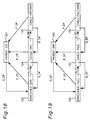
IC card 101 is described below with reference to Fig. 18 usingdirectory 121 and itschild directories - Each of the
child directories common parent directory 121 managing the child directories. Theparent directory 121, however, stores a pointer C_DF to thefirst directory 123 created under theparent directory 121. Each of thechild directories directory 123 in this example), however, is 0000, and the N_DF value in the last child directory (directory 125 in this example) is 0000. The relationships between the parent directory and the child directories can be obtained from these pointers. It is also possible that the parent directory is themaster directory 120. - The relationships between the
files master directory 120 in thisIC card 101 are described below with reference to Fig. 19. Each of thefiles common parent directory 120 managing these files. Theparent directory 120 stores a pointer C_EF to the first file created (file 130), and each of thefiles master directory 120. - Management of directories and files is made easier in an
IC card 101 according to this embodiment by means of pointers to the hierarchically arranged directories and files. The processes for deleting, reordering, and expanding files in thisIC card 101 are described next. - The file deletion process is described with reference to the flow chart in Fig. 20.
- The file to be deleted ("EF" is used for a "file" in the figures and below) is specified by command. The specified file EF is designated invalid to other operations using a
flag 160. Deleting the specified file EF, however, also makes it necessary to update the pointers in all files and directories (DF in the figures and below) referring to the pointer of the file to be deleted. - The first step in this process is to determine whether the value of the pointer N_EF to the file created after the deletion file EF is 0000; if it is, no file was created after EF, and the procedure advances to the next step. If N_EF does not equal 0000, there is a file after the file EF to be deleted from the hierarchy. The value of the B_EF pointer to the file preceding the file EF specified for deletion is therefore substituted for the value of the B_EF pointer in the following file. The value of the B_EF pointer in the deletion file EF can be 0000 at this time (i.e., the file being deleted is the first file in the directory).
- The next step is to determine whether the value of the pointer B_EF to the file created before the deletion file EF is 0000; if it is, no file proceeds the file EF to be deleted in the directory, and the specified file EF is the first file in the directory. It is therefore necessary to update the C_EF pointer of the parent directory to the N_EF pointer value of the selected file, i.e., to the file following the first file in the directory. If the B_EF pointer value is not 0000, there is a file higher in the hierarchy than the deletion file EF, and the N_EF pointer in that higher file must be updated to the N_EF pointer of the selected file EF, which points to the file following the selected file EF in the hierarchy.
- After the file is deleted, it is necessary to update the information to eliminate resulting open addresses. If the physical address of the selected file EF is not the first address in the user area of the memory, the file preceding the selected file EF must be located in the user area. If the located file is an invalid file, i.e., there are two consecutive invalidated files in memory, it is necessary to combine the two files into one. The size of the selected file EF is therefore added to the size of the located file, and the combined area of the selected and located files is redefined as the selected file EF.
- If the physical address of the area following the selected file EF in memory is the write pointer, the last file EF in memory has been deleted. The file write pointer is updated to the starting address of the selected file EF, and the process ends. If the next memory area is a valid file, the process also ends. If the next memory area is an invalid file, i.e., there are consecutive invalid files in memory, the size of the selected file EF is added to the size of the located file, and the area following the selected file EF is again checked.
- The file reordering process is described with reference to the flow chart in Fig. 21.
- The starting address of the user area of the memory is stored to the search pointer (in the processing buffer). The file structure is then searched until the area indicated by the search pointer is an invalid file EF. If the search pointer is the file write pointer, processing ends because there are no invalid files in memory. If the search pointer is to a valid file, the size of the valid file is added to the search pointer to update the search pointer. If the search pointer is to an invalid file, the size of the invalid file is added to the move size (in the processing buffer), and the following process is executed.
- To store the valid files to the smallest possible contiguous memory area, the valid files following the located invalid file are moved by the move size to the address indicated by the search pointer. If there are any files or directories with a pointer to the moved files, those pointers must also be updated.
- If the N_EF pointer to the file following the selected file EF is 0000, there is no file after the selected file EF, and the process advances. If the N_EF pointer is not 0000, there is a file following the selected file EF, and the B_EF pointer of the file pointed to by the N_EF pointer is assigned to the search pointer. There does not have to be a file preceding the selected file EF at this time (B_EF = 0000).
- The value of the B_EF pointer of the selected file EF is then evaluated. If B_EF = 0000, there is no preceding file and the selected file EF is the first file in the managing directory. The search pointer is therefore substituted for the C_EF pointer to the first file created in the managing directory. If B_EF ≠ 0000, there is a preceding file and the N_EF pointer of that preceding file is therefore assigned to the search pointer.
- The search pointer is updated by adding the size of the moved valid files to the search pointer. If the area at the address indicated by the search pointer plus the move size is the file write pointer, the search pointer is substituted for the write pointer and the process ends. If the next area is a valid file, the same process is repeated starting from the file movement process. If the next area is an invalid file, the move size is increased by the size of the invalid file, and the same process is repeated starting from the file movement process.
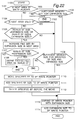
- If the size of a single file is increased in this file structure using a file capacity expansion means as described below in order to more effectively use a single file, unused areas will occur in memory, again making it necessary to reorder the files. This file size expansion process is described with reference to the flow chart in Fig. 22 below
- The file to be expanded and the expansion size are specified by commands. If the physical address in memory after the end address of the specified file is the file write pointer, it is determined whether there is sufficient open memory from the write pointer to increase the file size by the expansion size. If there is not, the process ends. If there is, the file size is increased and the write pointer is updated. Specifically, the size of the specified file EF is updated to the original size plus the expansion size, and the write pointer is also updated to the write pointer plus the expansion size.
- If the physical address in memory after the end address of the specified file is a valid file, it is determined whether the open memory area following the write pointer is larger than the selected file size plus the expansion size. If there is not, the process ends. If there is, the specified file is copied to the address indicated by the write pointer, and the write pointer is updated by adding the specified file size to the original write pointer. The copied source file is designated an invalid file using the file deletion process described above. The expansion size is then added to the selected file size and the file size is updated, and the expansion size is added to the write pointer to update the write pointer.
- If the next physical address after the end address of the specified file is an invalid file, it is determined whether the invalid file size is equal to the expansion size or is at least 3 bytes (the size of management information of invalidated file) larger. If it is, the specified file is expanded by the size of the invalid file, i.e., the selected file size is updated by adding the size of the deleted file. If the size of the invalid file is larger than the expansion size by three bytes or more, the excess file area is defined as an invalid file. If the size of the invalid file is less than the expansion size, the process applied when a valid file follows the physical end address of the specified file is executed as described above.
- Multipurpose use of an IC card is enabled by the file deletion and file size expansion processes described above in a hierarchical file structure. Unused memory resulting from file deletion or expansion can be eliminated and the memory can be more effectively used because files can also be reordered in memory.
- By thus providing an access conditions controller relating to the level numbers of the file structure in non-volatile memory, and providing plural key information fields corresponding to the level numbers in volatile memory, an IC card compatible with a hierarchical file structure and capable of maintaining files secure from access by the card issuer can be provided.
- Hierarchical key information can also be efficiently retained or erased from memory as required by including in each file data for determining the level number of the file and the parent file of the file.
- An access control method of superior program size, processing speed, and expandability can be provided for a file structure enabling plural files to be simultaneously open by providing a means for updating the key information of the first file based on the relative locations in the hierarchical file structure of the first selected file and a second file newly selected on the same channel, copying part of the key information for each of the selected files other than the first file to the key information of the first file based on the relationship between these files and the second file, and resetting the key information of the second file.
- By thus managing the file directory hierarchically, an IC card according to the present invention can be used for many purposes, the directories and files can be easily accessed using plural pointers, file deletion, expansion, and optimization are possible, and the memory available to the IC card can be effectively used.
- The invention being thus described, it will be obvious that the same may be varied in many ways. Such variations are not to be regarded as a departure from the spirit and scope of the invention, and all such modifications as would be obvious to one skilled in the art are intended to be included within the scope of the following claims.
Claims (9)
- An integrated circuit card comprising:
a processing controller,
non-volatile memory means having plural files in a hierarchical structure, and each file having an access conditions controller relating to the level number of said hierarchical structure; and
volatile memory means having plural key data fields corresponding to the level numbers. - An integrated circuit card according to Claim 1 wherein the access conditions controller has information limiting the level number.
- An integrated circuit card comprising:
a processing controller,
non-volatile memory means having plural files in a hierarchical structure where each file contains level number information for identifying at least the level number of the file, and parent file information for identifying the parent file of the file in the hierarchical structure,
volatile memory means having plural key information fields corresponding to the level numbers, and comprising
means for obtaining the lowest level number L of the common branches in the hierarchical structure of a first selected file and a newly selected second file using the level number information and parent file information; and
means for holding the information of the field corresponding to level 1 to level L in the key information field, and abandoning all other field information. - An integrated circuit card comprising
a processing controller,
non-volatile memory means having plural files in a hierarchical structure, and
volatile memory means having n key information areas corresponding to the selected n (where n ≧ 2) files,
means for changing the contents of the key information area relating to the first file based on the relative positions in the hierarchical structure of the first of selected n files and a newly selected second file, and
means for copying part or all of the contents of the key information area of each file to the first key information area based on the relative positions in the hierarchical structure of the second file to each of the n-1 files other than the first file in the selection of n files. - An integrated circuit card comprising
a buffer,
memory means for storing data,
a processing controller which uses the buffer for processing and comprises:
input/output means for exchanging data with an external device,
command processor means for analyzing and processing commands received through the input/output means, and generating the response to a received command,
file manager means activated by the command processor for accessing data and data collections in memory, and
file generator means activated by the command processor for creating files,
said file manager means hierarchically managing files and the file management directory by means of addresses identifying single files and an address identifying a directory of plural files. - An integrated circuit card according to Claim 5 further comprising file deletion means for deleting a file specified by command.
- An integrated circuit card according to Claim 5 further comprising file expansion means for expanding the capacity of a file specified by command.
- An integrated circuit card according to Claim 1 further comprising file optimizing means for eliminating open areas containing no information in the memory, and compactly reordering the plural valid files in memory.
- An integrated circuit card according to Claim 8, further comprising means for specifying by command whether to compactly reorder plural valid files.
Applications Claiming Priority (4)
| Application Number | Priority Date | Filing Date | Title |
|---|---|---|---|
| JP4215817A JP2502894B2 (en) | 1992-08-13 | 1992-08-13 | IC card |
| JP215817/92 | 1992-08-13 | ||
| JP279884/92 | 1992-10-19 | ||
| JP4279884A JPH06131517A (en) | 1992-10-19 | 1992-10-19 | Ic card |
Publications (4)
| Publication Number | Publication Date |
|---|---|
| EP0583006A2 true EP0583006A2 (en) | 1994-02-16 |
| EP0583006A3 EP0583006A3 (en) | 1994-05-18 |
| EP0583006B1 EP0583006B1 (en) | 1998-09-09 |
| EP0583006B2 EP0583006B2 (en) | 2006-11-29 |
Family
ID=26521068
Family Applications (1)
| Application Number | Title | Priority Date | Filing Date |
|---|---|---|---|
| EP93112836A Expired - Lifetime EP0583006B2 (en) | 1992-08-13 | 1993-08-11 | IC card with hierarchical file structure |
Country Status (4)
| Country | Link |
|---|---|
| US (1) | US5408082A (en) |
| EP (1) | EP0583006B2 (en) |
| KR (1) | KR970006648B1 (en) |
| DE (1) | DE69320900T3 (en) |
Cited By (26)
| Publication number | Priority date | Publication date | Assignee | Title |
|---|---|---|---|---|
| EP0636998A1 (en) * | 1993-07-28 | 1995-02-01 | Oki Electric Industry Co., Ltd. | High-security ic card |
| EP0644513A2 (en) * | 1993-09-17 | 1995-03-22 | AT&T Corp. | A smartcard adapted for a plurality of service providers and for remote installation of same. |
| EP0674290A2 (en) * | 1994-02-25 | 1995-09-27 | Fujitsu Limited | Card type storage medium and card type storage medium issuing apparatus |
| WO1997002543A1 (en) * | 1995-07-05 | 1997-01-23 | International Business Machines Corporation | Processing of long messages in a process card |
| FR2752072A1 (en) * | 1996-08-01 | 1998-02-06 | Solaic Sa | CARD WITH INTEGRATED CIRCUIT COMPRISING FILES CLASSIFIED ACCORDING TO A TREE |
| DE19718115A1 (en) * | 1996-12-23 | 1998-06-25 | Ccs Chipcard & Comm Syst Gmbh | Smart card and method of using the smart card |
| WO1998059325A3 (en) * | 1997-06-23 | 1999-04-22 | Siemens Ag | Chip card for executing non-modifiable system program routines and replacement program routines allocated thereto, and method for operating the chip card |
| FR2774189A1 (en) * | 1998-01-23 | 1999-07-30 | Fujitsu Ltd | Method of management of a computer application selected from number of applications stored on smart card |
| EP0950982A2 (en) * | 1998-03-26 | 1999-10-20 | Kabushiki Kaisha Toshiba | Portable electronic apparatus |
| EP0973136A2 (en) * | 1998-07-16 | 2000-01-19 | Sony Corporation | Data storage device and data storage method |
| EP0973127A2 (en) * | 1998-07-16 | 2000-01-19 | Kabushiki Kaisha Toshiba | IC card, IC card processing system, and IC card processing method |
| EP0973135A2 (en) * | 1998-07-16 | 2000-01-19 | Sony Corporation | Information processing and data storage |
| FR2786008A1 (en) * | 1998-11-13 | 2000-05-19 | Gemplus Card Int | METHOD AND DEVICE FOR MONITORING THE LIFE CYCLE OF A PORTABLE OBJECT, IN PARTICULAR A CHIP CARD |
| EP1085395A2 (en) * | 1999-09-13 | 2001-03-21 | Phone.Com Inc. | Access control system for files on a memory card |
| FR2806813A1 (en) * | 2000-03-17 | 2001-09-28 | Jean Michel Poupeau | Smart card memory management system allowing card users access to a number of services offered by a town |
| EP1160745A2 (en) * | 2000-05-16 | 2001-12-05 | Sony Corporation | Data storage device and data storage method, information-processing apparatus and information-processing method, and program |
| US6360954B1 (en) * | 1997-10-22 | 2002-03-26 | Cambridge Consultants Limited | Portable cards |
| US6527190B1 (en) * | 1997-09-09 | 2003-03-04 | Siemens Aktiengesellschaft | Chip card with memory for programs which can be reloaded as a function of the application |
| EP1328910A1 (en) * | 2000-10-26 | 2003-07-23 | SCHLUMBERGER Systèmes | File sharing device in an integrated circuit |
| WO2003069551A2 (en) * | 2002-02-18 | 2003-08-21 | Axalto Sa | Data organization in a smart card |
| EP1403761A1 (en) * | 2001-06-27 | 2004-03-31 | Sony Corporation | Integrated circuit device, information processing device, information recording device memory management method, mobile terminal device, semiconductor integrated circuit device, and communication method using mobile terminal device |
| EP1467312A1 (en) | 2003-04-09 | 2004-10-13 | Sony Corporation | Data communication apparatus and method for managing memory in the same |
| EP1739564A1 (en) * | 2004-04-21 | 2007-01-03 | NTT DoCoMo INC. | Ic card and authority transfer control method |
| EP1739563A1 (en) * | 2004-04-21 | 2007-01-03 | NTT DoCoMo INC. | Ic card and access control method |
| EP1770659A1 (en) * | 2005-09-30 | 2007-04-04 | Kabushiki Kaisha Toshiba | Portable electronic device and IC card |
| CN101493715B (en) * | 2008-01-21 | 2010-11-03 | 联咏科技股份有限公司 | Charge pumping circuit |
Families Citing this family (38)
| Publication number | Priority date | Publication date | Assignee | Title |
|---|---|---|---|---|
| JPH0896106A (en) * | 1994-09-29 | 1996-04-12 | Mitsubishi Electric Corp | Ic card and ic card system |
| JP3691871B2 (en) * | 1995-03-20 | 2005-09-07 | 富士通株式会社 | Card type storage medium |
| US7224819B2 (en) * | 1995-05-08 | 2007-05-29 | Digimarc Corporation | Integrating digital watermarks in multimedia content |
| CN1133959C (en) * | 1996-03-11 | 2004-01-07 | 卡巴闭锁系统公开股份有限公司 | Identification medium with passive electronic data carrier |
| US7653595B2 (en) * | 1996-04-16 | 2010-01-26 | Restricted Spending Solutions LLC | Controlled entertainment spending account |
| US7143064B2 (en) * | 1996-04-16 | 2006-11-28 | Picciallo Michael J | Controlled entertainment spending account |
| US6044360A (en) * | 1996-04-16 | 2000-03-28 | Picciallo; Michael J. | Third party credit card |
| US5742035A (en) * | 1996-04-19 | 1998-04-21 | Kohut; Michael L. | Memory aiding device for credit card pin numbers |
| US6101477A (en) * | 1998-01-23 | 2000-08-08 | American Express Travel Related Services Company, Inc. | Methods and apparatus for a travel-related multi-function smartcard |
| US6357010B1 (en) * | 1998-02-17 | 2002-03-12 | Secure Computing Corporation | System and method for controlling access to documents stored on an internal network |
| DE19839847A1 (en) * | 1998-09-02 | 2000-03-09 | Ibm | Storage of data objects in the memory of a chip card |
| US6486897B1 (en) * | 1998-09-29 | 2002-11-26 | Apple Computer, Inc. | Multi-repository display system using separate presentation, adaptation and access layers |
| US6480935B1 (en) * | 1999-01-15 | 2002-11-12 | Todd Carper | Smart card memory management system and method |
| JP3389186B2 (en) | 1999-04-27 | 2003-03-24 | 松下電器産業株式会社 | Semiconductor memory card and reading device |
| AU5301700A (en) | 1999-05-28 | 2000-12-18 | Coca-Cola Company, The | Method and apparatus for surrogate control of network-based electronic transactions |
| US7305473B2 (en) * | 1999-05-28 | 2007-12-04 | The Coca-Cola Company | Provision of transparent proxy services to a user of a client device |
| US6938163B1 (en) | 1999-06-17 | 2005-08-30 | Telefonaktiebolaget Lm Ericsson (Publ) | Technique for securely storing data within a memory |
| EP1306760A4 (en) * | 2000-07-07 | 2009-07-01 | Fujitsu Ltd | Ic card |
| KR100555003B1 (en) * | 2001-06-04 | 2006-02-24 | 가부시끼가이샤 르네사스 테크놀로지 | Memory card |
| KR100859922B1 (en) * | 2001-07-05 | 2008-09-23 | 마츠시타 덴끼 산교 가부시키가이샤 | Recording apparatus, and medium, method |
| WO2003029937A2 (en) * | 2001-10-01 | 2003-04-10 | Schlumberger Systemes | Access to data stored in an embedded database |
| JP3880384B2 (en) * | 2001-12-06 | 2007-02-14 | 松下電器産業株式会社 | IC card |
| GB0207354D0 (en) * | 2002-03-28 | 2002-05-08 | Ibm | Inheritance of access controls within a hierarchy of data processing system resources |
| US6676022B1 (en) * | 2002-10-04 | 2004-01-13 | Mobile-Mind, Inc. | Smart card system with command queuing |
| JP2005122402A (en) * | 2003-10-15 | 2005-05-12 | Systemneeds Inc | Ic card system |
| CN1981271A (en) * | 2004-07-08 | 2007-06-13 | 松下电器产业株式会社 | Host device, storage device, and method for accessing storage device |
| JPWO2006006388A1 (en) * | 2004-07-08 | 2008-04-24 | 松下電器産業株式会社 | Host device, storage device, and access method to storage device |
| JP4781033B2 (en) * | 2004-08-10 | 2011-09-28 | キヤノン株式会社 | Authentication system, processing method, program, and recording medium |
| KR100684942B1 (en) * | 2005-02-07 | 2007-02-20 | 삼성전자주식회사 | Adaptive flash memory control device with multiple mapping schemes and flash memory system havintg the same |
| EP1791055A1 (en) * | 2005-11-23 | 2007-05-30 | Incard SA | IC card file system |
| WO2008010899A2 (en) * | 2006-06-30 | 2008-01-24 | Electronics Plastics, Llc | Biometric embedded device |
| US20080097924A1 (en) * | 2006-10-20 | 2008-04-24 | Electronic Plastics, Llc | Decentralized secure transaction system |
| US20080104008A1 (en) * | 2006-10-31 | 2008-05-01 | Brantley David L | Common data broker method, system, and program product |
| JP4952600B2 (en) * | 2008-02-01 | 2012-06-13 | 富士通株式会社 | Management device and management program |
| EP2096884A1 (en) | 2008-02-29 | 2009-09-02 | Koninklijke KPN N.V. | Telecommunications network and method for time-based network access |
| JP5454864B2 (en) * | 2009-03-18 | 2014-03-26 | 株式会社東芝 | IC card and portable terminal system |
| JP2011090436A (en) * | 2009-10-21 | 2011-05-06 | Sony Corp | Information processor, communication device, and program |
| GB2507497B (en) * | 2012-10-30 | 2015-01-14 | Barclays Bank Plc | Device and method for secure memory access |
Citations (3)
| Publication number | Priority date | Publication date | Assignee | Title |
|---|---|---|---|---|
| FR2635891A1 (en) * | 1988-08-26 | 1990-03-02 | Toshiba Kk | PORTABLE ELECTRONIC DEVICE HAVING KEY DATA LIMITING ACCESS TO MEMORY |
| EP0479655A1 (en) * | 1990-10-02 | 1992-04-08 | Gemplus Card International S.A. | Integrated circuit for a microprocessor-card with multiple programms in programmable memory |
| WO1992013322A1 (en) * | 1991-01-18 | 1992-08-06 | Gemplus Card International | Secured method for loading a plurality of applications into a microprocessor memory card |
Family Cites Families (6)
| Publication number | Priority date | Publication date | Assignee | Title |
|---|---|---|---|---|
| US4849614A (en) * | 1985-12-27 | 1989-07-18 | Toppan Moore Company, Ltd. | Composite IC card |
| US4816653A (en) * | 1986-05-16 | 1989-03-28 | American Telephone And Telegraph Company | Security file system for a portable data carrier |
| DE68919483T2 (en) * | 1988-02-20 | 1995-04-06 | Fujitsu Ltd | Smart cards. |
| US5161256A (en) * | 1988-08-26 | 1992-11-03 | Kabushiki Kaisha Toshiba | Method and system for allocating file area in memory area of ic card |
| JPH02214994A (en) * | 1989-02-15 | 1990-08-27 | Hitachi Maxell Ltd | Ic card |
| JPH049715A (en) * | 1990-04-27 | 1992-01-14 | Tonen Corp | Data storage system using memory card |
-
1993
- 1993-08-11 EP EP93112836A patent/EP0583006B2/en not_active Expired - Lifetime
- 1993-08-11 DE DE69320900T patent/DE69320900T3/en not_active Expired - Lifetime
- 1993-08-12 US US08/105,646 patent/US5408082A/en not_active Expired - Lifetime
- 1993-08-12 KR KR1019930015609A patent/KR970006648B1/en not_active IP Right Cessation
Patent Citations (3)
| Publication number | Priority date | Publication date | Assignee | Title |
|---|---|---|---|---|
| FR2635891A1 (en) * | 1988-08-26 | 1990-03-02 | Toshiba Kk | PORTABLE ELECTRONIC DEVICE HAVING KEY DATA LIMITING ACCESS TO MEMORY |
| EP0479655A1 (en) * | 1990-10-02 | 1992-04-08 | Gemplus Card International S.A. | Integrated circuit for a microprocessor-card with multiple programms in programmable memory |
| WO1992013322A1 (en) * | 1991-01-18 | 1992-08-06 | Gemplus Card International | Secured method for loading a plurality of applications into a microprocessor memory card |
Non-Patent Citations (4)
| Title |
|---|
| A working draft of standard ISO/IEC 7816-4 † |
| F. Guez et al., Les cartes à microcircuit, Techniques et applications, Paris 1988, IBN 2-225-81346-9, pages 153 to 156. † |
| Interim European Telecommunication Standard, 2nd Final Draft pr I-ETS 300 045, February 1992, Reference:GSM 11.11 - version 3.10.0, pages 1 to 99, in particular chapter 3.4.2 "Semantics of the data field" (pages 11/12) and page 40 "SIM Implementation Model". Standard TE9, superseded by standard BS EN 726-3. † |
| Standard CEN/TC 224 N 16, dated 07.05.1990: Requirements for intelligent cards and terminals for telecommunication use - Part 2 Application independent card requirements (Draft 3). Source: STC TE9 Project Team 14. † |
Cited By (54)
| Publication number | Priority date | Publication date | Assignee | Title |
|---|---|---|---|---|
| US5592619A (en) * | 1993-07-28 | 1997-01-07 | Oki Electric Industry Co., Ltd. | High-security IC card |
| EP0636998A1 (en) * | 1993-07-28 | 1995-02-01 | Oki Electric Industry Co., Ltd. | High-security ic card |
| EP0644513A3 (en) * | 1993-09-17 | 2000-04-26 | AT&T Corp. | A smartcard adapted for a plurality of service providers and for remote installation of same. |
| EP0644513A2 (en) * | 1993-09-17 | 1995-03-22 | AT&T Corp. | A smartcard adapted for a plurality of service providers and for remote installation of same. |
| EP0674290A2 (en) * | 1994-02-25 | 1995-09-27 | Fujitsu Limited | Card type storage medium and card type storage medium issuing apparatus |
| EP0674290A3 (en) * | 1994-02-25 | 2000-10-04 | Fujitsu Limited | Card type storage medium and card type storage medium issuing apparatus |
| WO1997002543A1 (en) * | 1995-07-05 | 1997-01-23 | International Business Machines Corporation | Processing of long messages in a process card |
| FR2752072A1 (en) * | 1996-08-01 | 1998-02-06 | Solaic Sa | CARD WITH INTEGRATED CIRCUIT COMPRISING FILES CLASSIFIED ACCORDING TO A TREE |
| WO1998006071A1 (en) * | 1996-08-01 | 1998-02-12 | Solaic | Integrated circuit card comprising files classified in a tree structure |
| DE19718115A1 (en) * | 1996-12-23 | 1998-06-25 | Ccs Chipcard & Comm Syst Gmbh | Smart card and method of using the smart card |
| WO1998059325A3 (en) * | 1997-06-23 | 1999-04-22 | Siemens Ag | Chip card for executing non-modifiable system program routines and replacement program routines allocated thereto, and method for operating the chip card |
| US6527190B1 (en) * | 1997-09-09 | 2003-03-04 | Siemens Aktiengesellschaft | Chip card with memory for programs which can be reloaded as a function of the application |
| US6360954B1 (en) * | 1997-10-22 | 2002-03-26 | Cambridge Consultants Limited | Portable cards |
| US7308433B1 (en) | 1998-01-23 | 2007-12-11 | Fujitsu Limited | Application managing method and information processing apparatus using the method |
| FR2774189A1 (en) * | 1998-01-23 | 1999-07-30 | Fujitsu Ltd | Method of management of a computer application selected from number of applications stored on smart card |
| EP0950982A2 (en) * | 1998-03-26 | 1999-10-20 | Kabushiki Kaisha Toshiba | Portable electronic apparatus |
| EP0950982A3 (en) * | 1998-03-26 | 2000-05-10 | Kabushiki Kaisha Toshiba | Portable electronic apparatus |
| US6286757B1 (en) | 1998-03-26 | 2001-09-11 | Kabushiki Kaisha Toshiba | Portable electronic apparatus |
| EP0973136A3 (en) * | 1998-07-16 | 2002-01-23 | Sony Corporation | Data storage device and data storage method |
| US7003671B1 (en) | 1998-07-16 | 2006-02-21 | Sony Corporation | Information processing device and information processing method |
| EP0973136A2 (en) * | 1998-07-16 | 2000-01-19 | Sony Corporation | Data storage device and data storage method |
| EP0973135A3 (en) * | 1998-07-16 | 2001-11-07 | Sony Corporation | Information processing and data storage |
| US7613301B2 (en) | 1998-07-16 | 2009-11-03 | Sony Corporation | Data storage device and data storage method |
| US6363456B1 (en) | 1998-07-16 | 2002-03-26 | Kabushiki Kaisha Toshiba | IC card, IC card processing system, and IC card processing method |
| EP0973135A2 (en) * | 1998-07-16 | 2000-01-19 | Sony Corporation | Information processing and data storage |
| EP0973127A3 (en) * | 1998-07-16 | 2001-01-03 | Kabushiki Kaisha Toshiba | IC card, IC card processing system, and IC card processing method |
| EP0973127A2 (en) * | 1998-07-16 | 2000-01-19 | Kabushiki Kaisha Toshiba | IC card, IC card processing system, and IC card processing method |
| US7681029B1 (en) | 1998-11-13 | 2010-03-16 | Gemalto Sa | Method and device for controlling a portable object life cycle, in particular a smart card |
| WO2000030030A1 (en) * | 1998-11-13 | 2000-05-25 | Gemplus | Method and device for controlling a portable object life cycle, in particular a smart card |
| FR2786008A1 (en) * | 1998-11-13 | 2000-05-19 | Gemplus Card Int | METHOD AND DEVICE FOR MONITORING THE LIFE CYCLE OF A PORTABLE OBJECT, IN PARTICULAR A CHIP CARD |
| EP1085395A3 (en) * | 1999-09-13 | 2002-09-11 | Phone.Com Inc. | Access control system for files on a memory card |
| EP1085395A2 (en) * | 1999-09-13 | 2001-03-21 | Phone.Com Inc. | Access control system for files on a memory card |
| FR2806813A1 (en) * | 2000-03-17 | 2001-09-28 | Jean Michel Poupeau | Smart card memory management system allowing card users access to a number of services offered by a town |
| EP1160745A2 (en) * | 2000-05-16 | 2001-12-05 | Sony Corporation | Data storage device and data storage method, information-processing apparatus and information-processing method, and program |
| US6789166B2 (en) | 2000-05-16 | 2004-09-07 | Sony Corporation | Methods and apparatus for facilitating data communications between a data storage device and an information-processing apparatus |
| EP1160745A3 (en) * | 2000-05-16 | 2004-03-31 | Sony Corporation | Data storage device and data storage method, information-processing apparatus and information-processing method, and program |
| EP1328910A1 (en) * | 2000-10-26 | 2003-07-23 | SCHLUMBERGER Systèmes | File sharing device in an integrated circuit |
| EP1403761A1 (en) * | 2001-06-27 | 2004-03-31 | Sony Corporation | Integrated circuit device, information processing device, information recording device memory management method, mobile terminal device, semiconductor integrated circuit device, and communication method using mobile terminal device |
| EP1403761A4 (en) * | 2001-06-27 | 2004-11-17 | Sony Corp | Integrated circuit device, information processing device, information recording device memory management method, mobile terminal device, semiconductor integrated circuit device, and communication method using mobile terminal device |
| US7508946B2 (en) | 2001-06-27 | 2009-03-24 | Sony Corporation | Integrated circuit device, information processing apparatus, memory management method for information storage device, mobile terminal apparatus, semiconductor integrated circuit device, and communication method using mobile terminal apparatus |
| US9384618B2 (en) | 2001-06-27 | 2016-07-05 | Sony Corporation | Integrated circuit device, information processing apparatus, memory management method for information storage device, mobile terminal apparatus, semiconductor integrated circuit device, and communication method using mobile terminal apparatus |
| WO2003069551A2 (en) * | 2002-02-18 | 2003-08-21 | Axalto Sa | Data organization in a smart card |
| WO2003069551A3 (en) * | 2002-02-18 | 2004-12-29 | Axalto Sa | Data organization in a smart card |
| CN100334547C (en) * | 2002-02-18 | 2007-08-29 | 雅斯拓股份有限公司 | Data organization in a smart card |
| EP1467312A1 (en) | 2003-04-09 | 2004-10-13 | Sony Corporation | Data communication apparatus and method for managing memory in the same |
| US7194591B2 (en) | 2003-04-09 | 2007-03-20 | Sony Corporation | Data communication apparatus and method for managing memory in the same |
| SG129282A1 (en) * | 2003-04-09 | 2007-02-26 | Sony Corp | Data communication apparatus and method for managing memory in the same |
| EP1739563A4 (en) * | 2004-04-21 | 2009-02-18 | Ntt Docomo Inc | Ic card and access control method |
| EP1739564A4 (en) * | 2004-04-21 | 2009-08-26 | Ntt Docomo Inc | Ic card and authority transfer control method |
| EP1739563A1 (en) * | 2004-04-21 | 2007-01-03 | NTT DoCoMo INC. | Ic card and access control method |
| US7814557B2 (en) | 2004-04-21 | 2010-10-12 | Ntt Docomo, Inc. | IC card and access control method |
| EP1739564A1 (en) * | 2004-04-21 | 2007-01-03 | NTT DoCoMo INC. | Ic card and authority transfer control method |
| EP1770659A1 (en) * | 2005-09-30 | 2007-04-04 | Kabushiki Kaisha Toshiba | Portable electronic device and IC card |
| CN101493715B (en) * | 2008-01-21 | 2010-11-03 | 联咏科技股份有限公司 | Charge pumping circuit |
Also Published As
| Publication number | Publication date |
|---|---|
| EP0583006A3 (en) | 1994-05-18 |
| DE69320900D1 (en) | 1998-10-15 |
| EP0583006B2 (en) | 2006-11-29 |
| US5408082A (en) | 1995-04-18 |
| KR970006648B1 (en) | 1997-04-29 |
| DE69320900T3 (en) | 2007-04-26 |
| DE69320900T2 (en) | 1999-01-28 |
| EP0583006B1 (en) | 1998-09-09 |
| KR940004469A (en) | 1994-03-15 |
Similar Documents
| Publication | Publication Date | Title |
|---|---|---|
| US5408082A (en) | IC card with hierarchical file structure | |
| KR910002257B1 (en) | Portable electronic device | |
| US5517014A (en) | File management apparatus for IC card | |
| US5226155A (en) | Method and system for allocating file space in memory of ic card | |
| JPH06504862A (en) | A secure way to load multiple applications onto a microprocessor memory card | |
| US5608902A (en) | File management system for memory card | |
| JPH0793203A (en) | File managing system | |
| US4027288A (en) | Self-managing variable field storage system for handling nested data structures | |
| JPH06282471A (en) | File control system | |
| JP2502894B2 (en) | IC card | |
| JP2575358B2 (en) | IC card | |
| JP3420761B2 (en) | A secure way to load multiple applications on a microprocessor memory card | |
| KR100350972B1 (en) | Computer system and method possessing the function of storing an ID in its ROM | |
| US6496829B1 (en) | Information processing apparatus, information processing method, and computer-readable storage medium for storing information processing program | |
| US7296289B2 (en) | Setting or changing an access condition for an access management apparatus and method of a portable electronic device | |
| CN108376227B (en) | File access method and system of security chip | |
| JP2609645B2 (en) | Portable electronic devices | |
| JPH089795Y2 (en) | IC card | |
| JP2520583B2 (en) | IC card | |
| JPH09305449A (en) | Data base managing system | |
| JPH0827824B2 (en) | IC card | |
| JPH09231110A (en) | Ic card | |
| JP2008016050A (en) | Ic card | |
| JPH06274398A (en) | File control system | |
| JPH05265821A (en) | Index managing system for data base |
Legal Events
| Date | Code | Title | Description |
|---|---|---|---|
| PUAI | Public reference made under article 153(3) epc to a published international application that has entered the european phase |
Free format text: ORIGINAL CODE: 0009012 |
|
| 17P | Request for examination filed |
Effective date: 19930811 |
|
| AK | Designated contracting states |
Kind code of ref document: A2 Designated state(s): DE FR GB |
|
| PUAL | Search report despatched |
Free format text: ORIGINAL CODE: 0009013 |
|
| AK | Designated contracting states |
Kind code of ref document: A3 Designated state(s): DE FR GB |
|
| 17Q | First examination report despatched |
Effective date: 19970410 |
|
| GRAG | Despatch of communication of intention to grant |
Free format text: ORIGINAL CODE: EPIDOS AGRA |
|
| GRAG | Despatch of communication of intention to grant |
Free format text: ORIGINAL CODE: EPIDOS AGRA |
|
| GRAH | Despatch of communication of intention to grant a patent |
Free format text: ORIGINAL CODE: EPIDOS IGRA |
|
| GRAH | Despatch of communication of intention to grant a patent |
Free format text: ORIGINAL CODE: EPIDOS IGRA |
|
| GRAA | (expected) grant |
Free format text: ORIGINAL CODE: 0009210 |
|
| AK | Designated contracting states |
Kind code of ref document: B1 Designated state(s): DE FR GB |
|
| REF | Corresponds to: |
Ref document number: 69320900 Country of ref document: DE Date of ref document: 19981015 |
|
| ET | Fr: translation filed | ||
| PLBI | Opposition filed |
Free format text: ORIGINAL CODE: 0009260 |
|
| 26 | Opposition filed |
Opponent name: GEMPLUS SCA Effective date: 19990609 |
|
| PLBF | Reply of patent proprietor to notice(s) of opposition |
Free format text: ORIGINAL CODE: EPIDOS OBSO |
|
| PLBF | Reply of patent proprietor to notice(s) of opposition |
Free format text: ORIGINAL CODE: EPIDOS OBSO |
|
| RDAH | Patent revoked |
Free format text: ORIGINAL CODE: EPIDOS REVO |
|
| APAC | Appeal dossier modified |
Free format text: ORIGINAL CODE: EPIDOS NOAPO |
|
| APAE | Appeal reference modified |
Free format text: ORIGINAL CODE: EPIDOS REFNO |
|
| APAC | Appeal dossier modified |
Free format text: ORIGINAL CODE: EPIDOS NOAPO |
|
| REG | Reference to a national code |
Ref country code: GB Ref legal event code: IF02 |
|
| APCC | Communication from the board of appeal sent |
Free format text: ORIGINAL CODE: EPIDOS OBAPO |
|
| APCA | Receipt of observations in appeal recorded |
Free format text: ORIGINAL CODE: EPIDOSNOBA4O |
|
| APAH | Appeal reference modified |
Free format text: ORIGINAL CODE: EPIDOSCREFNO |
|
| PLAB | Opposition data, opponent's data or that of the opponent's representative modified |
Free format text: ORIGINAL CODE: 0009299OPPO |
|
| R26 | Opposition filed (corrected) |
Opponent name: GEMPLUS SCA Effective date: 19990609 |
|
| APBU | Appeal procedure closed |
Free format text: ORIGINAL CODE: EPIDOSNNOA9O |
|
| PUAH | Patent maintained in amended form |
Free format text: ORIGINAL CODE: 0009272 |
|
| STAA | Information on the status of an ep patent application or granted ep patent |
Free format text: STATUS: PATENT MAINTAINED AS AMENDED |
|
| 27A | Patent maintained in amended form |
Effective date: 20061129 |
|
| AK | Designated contracting states |
Kind code of ref document: B2 Designated state(s): DE FR GB |
|
| ET3 | Fr: translation filed ** decision concerning opposition | ||
| PGFP | Annual fee paid to national office [announced via postgrant information from national office to epo] |
Ref country code: GB Payment date: 20120808 Year of fee payment: 20 |
|
| PGFP | Annual fee paid to national office [announced via postgrant information from national office to epo] |
Ref country code: FR Payment date: 20120823 Year of fee payment: 20 Ref country code: DE Payment date: 20120808 Year of fee payment: 20 |
|
| REG | Reference to a national code |
Ref country code: DE Ref legal event code: R071 Ref document number: 69320900 Country of ref document: DE |
|
| REG | Reference to a national code |
Ref country code: GB Ref legal event code: PE20 Expiry date: 20130810 |
|
| PG25 | Lapsed in a contracting state [announced via postgrant information from national office to epo] |
Ref country code: DE Free format text: LAPSE BECAUSE OF EXPIRATION OF PROTECTION Effective date: 20130813 |
|
| PG25 | Lapsed in a contracting state [announced via postgrant information from national office to epo] |
Ref country code: GB Free format text: LAPSE BECAUSE OF EXPIRATION OF PROTECTION Effective date: 20130810 |