EP0583075A1 - Method and apparatus for measuring meteorological visibility and scattering of light - Google Patents
Method and apparatus for measuring meteorological visibility and scattering of light Download PDFInfo
- Publication number
- EP0583075A1 EP0583075A1 EP93305511A EP93305511A EP0583075A1 EP 0583075 A1 EP0583075 A1 EP 0583075A1 EP 93305511 A EP93305511 A EP 93305511A EP 93305511 A EP93305511 A EP 93305511A EP 0583075 A1 EP0583075 A1 EP 0583075A1
- Authority
- EP
- European Patent Office
- Prior art keywords
- optical
- signal
- receiver
- measuring
- light
- Prior art date
- Legal status (The legal status is an assumption and is not a legal conclusion. Google has not performed a legal analysis and makes no representation as to the accuracy of the status listed.)
- Granted
Links
Images


Classifications
-
- G—PHYSICS
- G01—MEASURING; TESTING
- G01S—RADIO DIRECTION-FINDING; RADIO NAVIGATION; DETERMINING DISTANCE OR VELOCITY BY USE OF RADIO WAVES; LOCATING OR PRESENCE-DETECTING BY USE OF THE REFLECTION OR RERADIATION OF RADIO WAVES; ANALOGOUS ARRANGEMENTS USING OTHER WAVES
- G01S7/00—Details of systems according to groups G01S13/00, G01S15/00, G01S17/00
- G01S7/48—Details of systems according to groups G01S13/00, G01S15/00, G01S17/00 of systems according to group G01S17/00
- G01S7/481—Constructional features, e.g. arrangements of optical elements
- G01S7/4818—Constructional features, e.g. arrangements of optical elements using optical fibres
-
- G—PHYSICS
- G01—MEASURING; TESTING
- G01N—INVESTIGATING OR ANALYSING MATERIALS BY DETERMINING THEIR CHEMICAL OR PHYSICAL PROPERTIES
- G01N21/00—Investigating or analysing materials by the use of optical means, i.e. using sub-millimetre waves, infrared, visible or ultraviolet light
- G01N21/17—Systems in which incident light is modified in accordance with the properties of the material investigated
- G01N21/47—Scattering, i.e. diffuse reflection
- G01N21/49—Scattering, i.e. diffuse reflection within a body or fluid
- G01N21/53—Scattering, i.e. diffuse reflection within a body or fluid within a flowing fluid, e.g. smoke
- G01N21/538—Scattering, i.e. diffuse reflection within a body or fluid within a flowing fluid, e.g. smoke for determining atmospheric attenuation and visibility
-
- G—PHYSICS
- G01—MEASURING; TESTING
- G01S—RADIO DIRECTION-FINDING; RADIO NAVIGATION; DETERMINING DISTANCE OR VELOCITY BY USE OF RADIO WAVES; LOCATING OR PRESENCE-DETECTING BY USE OF THE REFLECTION OR RERADIATION OF RADIO WAVES; ANALOGOUS ARRANGEMENTS USING OTHER WAVES
- G01S17/00—Systems using the reflection or reradiation of electromagnetic waves other than radio waves, e.g. lidar systems
- G01S17/88—Lidar systems specially adapted for specific applications
-
- G—PHYSICS
- G01—MEASURING; TESTING
- G01N—INVESTIGATING OR ANALYSING MATERIALS BY DETERMINING THEIR CHEMICAL OR PHYSICAL PROPERTIES
- G01N21/00—Investigating or analysing materials by the use of optical means, i.e. using sub-millimetre waves, infrared, visible or ultraviolet light
- G01N21/17—Systems in which incident light is modified in accordance with the properties of the material investigated
- G01N21/47—Scattering, i.e. diffuse reflection
- G01N2021/4704—Angular selective
- G01N2021/4709—Backscatter
Definitions
- the present invention relates to a method in accordance with the preamble of claim 1 for measuring meteorological visibility and scattering of light.
- the invention also concerns an apparatus for measuring meteorological visibility and scattering of light.
- EP patent application 89309088.6 (Vaisala Oy) describes a measurement system for the scattering of light, in which system the active surface of the transmitter and the receiver is formed into a single surface by means of, e.g., combined optical fiber bundles.
- the invention is based on adapting a second photoresponsive feedback element into the measurement system in such a point of the system that receives the transmitted optical signal at the same power level as the system receiver proper receives the stray signal owing to the optical stray coupling, while the feedback element receives none of the optical signal imposed on the system by external reflections or backscatter.
- the receiving element proper and the feedback element should be as identical as possible both in sensitivity and response time.
- the invention offers significant benefits.
- the invention makes it possible to avoid overloading of the receiver proper immediately after the transmitted pulse, which significantly improves measurements, particularly in the near range. Furthermore, errors in far-range measurements are reduced.
- an optical measurement system based on a beam splitter comprises a transmitter 1, from which an optical pulse is emitted via a beam splitter 5 to a lens 7, which launches the light pulse to a desired spatial angle.
- a window 9 is employed to prevent contamination of the optical element 7.
- the beam splitter 5 guides the returning light to a receiver 3.
- Adapted to the receiver 3 is also a unit 2 which is synchronized to the transmitter 1 and is capable of determining the delay and intensity of the return pulse, whereby such information can be utilized to define the object from which the reflection of the optical signal takes place.
- a Y-coupler 11 implemented by means of optical fibers takes place in the same manner as in the embodiment illustrated in Fig. 1.
- the beam splitter is replaced by a Y-coupler 11, which achieves a better directional gain for guiding the optical measurement signal to the desired object, since the losses by the upward reflection (cf. Fig. 1) caused by the beam splitter are avoided.
- the Y-coupler 11 has a drawback of optical signal stray coupling within the common part of the divider directly into the receiver input fibers during the transmission of the outgoing pulse. Hence, similar problems are involved as those discussed in conjunction with Fig. 1.
- the upper diagram of Fig. 3 shows the optical input of a receiver.
- the optical stray signal caused by the above-described reasons at the start of the measurement cycle loads the receiver input with a transient pulse signal 34 of approx. 1000-...1,000,000-fold intensity 35 compared with the normal signal level.
- said transient pulse signal 34 drives the receiver input amplifier into saturation during the period 33.
- the amplifier recovers from saturation, and though a backscatter input signal component 36 caused by mist is present, it cannot be detected from the amplifier output signal due to overload distortion 32.
- a reflection from a cloud or fixed object is present in the input signal. As is evident, also this later arriving signal can be corrupted by the overload distortion 32.
- amplifier overload can be avoided by configuring a conventional photoresponsive element 41 into a half-bridge with feedback element 42.
- the photoresponsive elements 41 and 42 are reverse-biased avalanche photodiodes.
- the stray signal coupled via optical stray coupling is canceled almost entirely.
- Bias adjustment of half-bridge permits fine-adjustment of the compensating effect of the feedback photodiode to a degree of substantially perfect cancellation of the transient signal resulting from optical stray coupling.
- Such arrangement achieves protection against overloading of the amplifier 43.
- the bias voltage can be continuously controlled by first converting the analog measurement signal into digital form with the help of an A/D converter 45 and then processing its digital output signal in an information processing unit 47.
- the A/D converter 45 used is typically a so-called FLASH converter operating with a sampling interval of 50 ns and resolution of 8 bits.
- the output signal of the A/D converter 45 is loaded in a FIFO (First-In/First-Out) register memory 48.
- the length of the intermediate register memory 48 can be. e.g., 512 samples.
- the microprocessor 47 is employed for controlling the sampling operation via a bus 54 which is connected to both the intermediate register memory 48 and the A/D converter 45.
- the fine-adjustment of the bias voltage is implemented through digitally steering from the information processing unit 47 a bias voltage generator 44 which controls the bias voltage over the photodiodes 41 and 42.
- the bias voltage control can be performed continuously without delay as the information processing unit senses the deviations in the stray signal cancellation accuracy of the measurement signal and can thus differentially either increase or decrease the bias voltage so as to achieve perfect stray signal cancellation.
- the bias voltage control is implemented by means of a constant-voltage regulator 40 connected to the positive supply voltage and an adjustable voltage regulator 44 which is connected to the negative supply voltage and receives its control voltage from the microprocessor 47 over the bus 56 via a D/A converter 58.
- the half-bridge 46 is advantageously complemented with a temperature-compensating circuit 49 which controls the voltage regulators 40 and 44.
- the half-bridge 46 formed by the diodes 41 and 42 can be considered a subtracting circuit which cancels the stray signal component from the measurement signal.
- the feedback of the optical signal in system based on a beam splitter 5 is implemented by means of an optical fiber 53 optically coupled to a feedback sensor element 51.
- the free end of the fiber 53 is placed to the opposite side of the beam splitter 5 relative to the receiver element 3.
- the length of the fiber 53 can be selected so that it produces a delay matching the delay of the most significant stray signal component. For instance, if the strongest stray signal component originates from the beam splitter, the delay caused by the fiber 53 must be adjusted to the delay on the optical path between the receiver 3 and the beam splitter.
- the delay caused by the fiber 53 must be adjusted to twice the delay on the optical path from the beam splitter 5 to the lens 7.
- the photoresponsive elements proper can be placed maximally tight to each other, whereby these elements can be kept in maximally identical ambient conditions.
- the free end of the fiber 53 can be made movable, thereby giving a further means of stray signal cancellation adjustment through moving the free end of the fiber 53, thus complementing the bias voltage control discussed above in conjunction with Fig. 4.
- the coarse adjustment is made mechanically bending the fiber end and then performing fine-adjustment by electronic means.
- the feedback signal can be taken via an optical power divider 61 when a Y-coupler is used.
- the power division ratio can be 2:2, for instance.
- the delay caused by the feedback fiber 65 between the optical power divider and the feedback signal sensor element 63 is adjusted essentially equal to the delay caused by the fiber 64 connecting the receiver 3 to the optical power divider 61.
- the invention is characterized in that the feedback sensor element is only used for measuring the stray signal component stemming from the optical stray coupling, particularly its waveform, which is scaled and equal phased prior to its subtraction from the uncorrected output signal of the receiver proper.
- the compensation of different delays can alternatively be arranged by means of digital delay circuits placed after the A/D converter, whereby both the measurement and the feedback signal can be delayed as necessary.
- the invention is particularly suited for use in conjunction with a Y-coupler implemented with optical fibers, while substantial benefits are also achieved in conjunction with measurement systems based on beam splitters illustrated in Figs. 1 and 5.
Abstract
Description
- The present invention relates to a method in accordance with the preamble of claim 1 for measuring meteorological visibility and scattering of light.
- The invention also concerns an apparatus for measuring meteorological visibility and scattering of light.
- EP patent application 89309088.6 (Vaisala Oy) describes a measurement system for the scattering of light, in which system the active surface of the transmitter and the receiver is formed into a single surface by means of, e.g., combined optical fiber bundles.
- FR patent application 2,594,535 also discloses an embodiment similar to that described above.
- Despite the significant benefits achieved by using a common active surface for both the transmitting and receiving systems via a single optical system, unexpected problems have been encountered. As the transmitted pulse has an extremely high peak intensity, the optical fibers of the transmitting system permit stray coupling to the adjacent fibers of the receiving system, whereby the receiver input amplifier is temporarily overloaded. This can cause problems particularly in near-range scattering measurement, since the receiver input amplifier is nonresponsive during the very time the near-range reflected information should typically be detected by the receiver.
- The same problem is also encountered in the conventional embodiments based on a beam splitter that have the further drawback of a partial loss of transmit power in the beam-splitting optical system.
- It is an object of the present invention to overcome the disadvantages related to the above-described prior-art techniques and to achieve an entirely novel method and apparatus for the measurement of the scattering of light, said apparatus using a common optical system for both transmission and reception.
- The invention is based on adapting a second photoresponsive feedback element into the measurement system in such a point of the system that receives the transmitted optical signal at the same power level as the system receiver proper receives the stray signal owing to the optical stray coupling, while the feedback element receives none of the optical signal imposed on the system by external reflections or backscatter. The receiving element proper and the feedback element should be as identical as possible both in sensitivity and response time.
- More specifically, the method according to the invention is characterized by what is stated in the characterizing part of claim 1.
- Furthermore, the apparatus according to the invention is characterized by what is stated in the characterizing part of
claim 5. - The invention offers significant benefits.
- The invention makes it possible to avoid overloading of the receiver proper immediately after the transmitted pulse, which significantly improves measurements, particularly in the near range. Furthermore, errors in far-range measurements are reduced.
- The invention is next examined in greater detail with the help of exemplifying embodiments illustrated in the appended drawing, in which
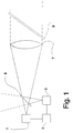
- Figure 1 shows diagrammatically a measurement system based on a beam splitter of conventional technology.
- Figure 2 shows diagrammatically a conventional measurement system based on a Y-coupler implemented with the help of optical fibers.
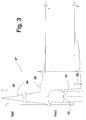
- Figure 3 shows in a graph the received optical input signal and the corresponding electrical output signal of the measurement system illustrated in Figs. 1 and 2.
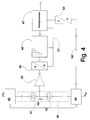
- Figure 4 shows a block diagram of the apparatus according to the invention.
- Figure 5 shows an arrangement according to the invention adapted to the basic embodiment illustrated in Fig. 1.
- Figure 6 shows an arrangement according to the invention adapted to the basic embodiment illustrated in Fig. 2.
- With reference to Fig. 1, an optical measurement system based on a beam splitter comprises a transmitter 1, from which an optical pulse is emitted via a
beam splitter 5 to alens 7, which launches the light pulse to a desired spatial angle. Awindow 9 is employed to prevent contamination of theoptical element 7. After the light pulse launched from theoptical element 7 propagates along a path until it meets an obstacle, a portion of the light is backscattered along the same path, whereby thebeam splitter 5 guides the returning light to areceiver 3. Adapted to thereceiver 3 is also aunit 2 which is synchronized to the transmitter 1 and is capable of determining the delay and intensity of the return pulse, whereby such information can be utilized to define the object from which the reflection of the optical signal takes place. Owing to the high peak intensity of the transmitted pulse, imperfections of thebeam splitter 5 impose a direct stray signal onto thereceiver 3. Due to the low intensity of the return signal, the input amplifier of thereceiver 3 must have a high gain, whereby the above-mentioned stray signal typically overloads the input amplifier of thereceiver 3. Stray signals with a short delay are also imposed onto the received return signal due to reflections from thelens 7 and thewindow 9. - With reference to Fig. 2, measurement using a Y-
coupler 11 implemented by means of optical fibers takes place in the same manner as in the embodiment illustrated in Fig. 1. In this embodiment the beam splitter is replaced by a Y-coupler 11, which achieves a better directional gain for guiding the optical measurement signal to the desired object, since the losses by the upward reflection (cf. Fig. 1) caused by the beam splitter are avoided. However, the Y-coupler 11 has a drawback of optical signal stray coupling within the common part of the divider directly into the receiver input fibers during the transmission of the outgoing pulse. Hence, similar problems are involved as those discussed in conjunction with Fig. 1. - The upper diagram of Fig. 3 shows the optical input of a receiver. The optical stray signal caused by the above-described reasons at the start of the measurement cycle loads the receiver input with a
transient pulse signal 34 of approx. 1000-...1,000,000-foldintensity 35 compared with the normal signal level. According to the lower diagram depicting the output signal of the receiver, saidtransient pulse signal 34 drives the receiver input amplifier into saturation during theperiod 33. During theperiod 31 the amplifier recovers from saturation, and though a backscatterinput signal component 36 caused by mist is present, it cannot be detected from the amplifier output signal due tooverload distortion 32. At instant 37 a reflection from a cloud or fixed object is present in the input signal. As is evident, also this later arriving signal can be corrupted by theoverload distortion 32. - With reference to Fig. 4, amplifier overload can be avoided by configuring a conventional
photoresponsive element 41 into a half-bridge withfeedback element 42. In the embodiment illustrated in the diagram thephotoresponsive elements diodes amplifier 43. The bias voltage can be continuously controlled by first converting the analog measurement signal into digital form with the help of an A/D converter 45 and then processing its digital output signal in aninformation processing unit 47. The A/D converter 45 used is typically a so-called FLASH converter operating with a sampling interval of 50 ns and resolution of 8 bits. Prior to being taken to themicroprocessor 47, the output signal of the A/D converter 45 is loaded in a FIFO (First-In/First-Out)register memory 48. The length of theintermediate register memory 48 can be. e.g., 512 samples. Themicroprocessor 47 is employed for controlling the sampling operation via abus 54 which is connected to both theintermediate register memory 48 and the A/D converter 45. The fine-adjustment of the bias voltage is implemented through digitally steering from the information processing unit 47 abias voltage generator 44 which controls the bias voltage over thephotodiodes voltage regulator 40 connected to the positive supply voltage and anadjustable voltage regulator 44 which is connected to the negative supply voltage and receives its control voltage from themicroprocessor 47 over thebus 56 via a D/A converter 58. The half-bridge 46 is advantageously complemented with a temperature-compensatingcircuit 49 which controls thevoltage regulators bridge 46 formed by thediodes - With reference to Fig. 5, the feedback of the optical signal in system based on a
beam splitter 5 is implemented by means of anoptical fiber 53 optically coupled to afeedback sensor element 51. The free end of thefiber 53 is placed to the opposite side of thebeam splitter 5 relative to thereceiver element 3. The length of thefiber 53 can be selected so that it produces a delay matching the delay of the most significant stray signal component. For instance, if the strongest stray signal component originates from the beam splitter, the delay caused by thefiber 53 must be adjusted to the delay on the optical path between thereceiver 3 and the beam splitter. If the strongest stray signal component originates from the focusing lens 7 (or lens group), the delay caused by thefiber 53 must be adjusted to twice the delay on the optical path from thebeam splitter 5 to thelens 7. By virtue of theoptical fiber 53, the photoresponsive elements proper can be placed maximally tight to each other, whereby these elements can be kept in maximally identical ambient conditions. The free end of thefiber 53 can be made movable, thereby giving a further means of stray signal cancellation adjustment through moving the free end of thefiber 53, thus complementing the bias voltage control discussed above in conjunction with Fig. 4. In practice the coarse adjustment is made mechanically bending the fiber end and then performing fine-adjustment by electronic means. - With reference to Fig. 6, the feedback signal can be taken via an
optical power divider 61 when a Y-coupler is used. The power division ratio can be 2:2, for instance. To optimize the feedback effect, the delay caused by thefeedback fiber 65 between the optical power divider and the feedbacksignal sensor element 63 is adjusted essentially equal to the delay caused by thefiber 64 connecting thereceiver 3 to theoptical power divider 61. - The invention is characterized in that the feedback sensor element is only used for measuring the stray signal component stemming from the optical stray coupling, particularly its waveform, which is scaled and equal phased prior to its subtraction from the uncorrected output signal of the receiver proper.
- Consequently, deviating from the implementation shown in Fig. 4, it is also possible within the scope of the invention to implement the feedback arrangement by means of separate sensors, which are used for the cancellation of the optical stray coupling after, e.g., a separate calibration step.
- The compensation of different delays can alternatively be arranged by means of digital delay circuits placed after the A/D converter, whereby both the measurement and the feedback signal can be delayed as necessary.
- The invention is particularly suited for use in conjunction with a Y-coupler implemented with optical fibers, while substantial benefits are also achieved in conjunction with measurement systems based on beam splitters illustrated in Figs. 1 and 5.
Claims (8)
- A method for measuring the meteorological visibility and the scattering of light, in which method- a light pulse is emitted into the atmosphere via an optical transmit system (7, 9),- intensity and delay of the backscattered light returned via the same optical transmit system (7, 9) are measured,- the waveform of the optical transient pulse generated within the apparatus in conjunction with the launching of the optical transmit pulse is sensed in a manner that excludes any backscattered light originating from outside the measurement system.- said sensed signal is scaled for both its magnitude and phase so as to achieve a suitable feedback signal relative to the actual measurement signal, and- said feedback signal is subtracted from said measurement signal to avoid overloading of the receiver.
- A method as defined in claim 1. characterized in that the sensed magnitude of said optical pulse generated inside the measurement system is scaled by means of half-bridge connected avalanche photodiodes (41, 42), whose bias voltage is controlled in order to obtain a suitable feedback signal.
- A method as defined in claim 2 in which method the return signal traveling back via an optical system (7) is taken to a receiver (3) via a beam splitter (5), characterized in that said optical pulse generated inside the measurement system is sensed via an optical fiber (53) whose one end is placed to the opposite side of the beam splitter (5) relative to the receiver element (3) and the other end is coupled to a feedback signal sensor (51).
- A method as defined in claim 2 in which method the return signal traveling back via an optical system (7) is taken to a receiver (3) via a Y-coupler (61), characterized in that said optical pulse generated inside the measurement system is sensed via an optical power divider (61) which is formed by said Y-coupler and thus couples the signal to the feedback signal sensor (63).
- An apparatus for measuring the meteorological visibility and the scattering of light, said apparatus comprising- transmission means (1) for generating a light pulse.- an optical transmit system (7, 9) for launching said light pulse into the atmosphere.- receive elements (3) for measuring the intensity of the backscattered light which travels back via said optical transmit system (7, 9), and- delay-measuring elements (2) for measuring the propagation delay of said backscattered light,- feedback elements (65, 63, 53, 51) for measuring the waveform of the optical transient pulse generated within the apparatus in conjunction with the launching of the optical transmit pulse, whereby the measurement is performed in a manner that excludes any backscattered light originating from outside the measurement system,- scaling elements (45, 47, 44) for scaling the signal measured with the help of said feedback elements (65, 63, 53, 51) for both its magnitude and phase so as to achieve a suitable feedback signal relative to the actual measurement signal, and- subtraction elements (46) for subtracting said feedback signal from said measurement signal to avoid overloading of the receiver.
- An apparatus as defined in claim 5, characterized in that said subtraction elements comprise a half-bridge (46) formed by a measuring and a feedback-sensing photodiode (41, 42) and said scaling elements comprise a bias voltage control element (44) for said half-bridge (46).
- An apparatus as defined in claim 6, said apparatus having a beam splitter (5) for routing the return signal traveling back via said optical transmit system (7, 9) to said receiver (3), characterized in that said apparatus incorporates an optical fiber (53) whose one end is placed to the opposite side of the beam splitter (5) relative to the receiver element (3) and the other end of the fiber (53) is coupled to a feedback signal sensor (42) employed for measuring the shape of the optical transient pulse generated within the apparatus.
- An apparatus as defined in claim 6, said apparatus having a Y-coupler (61) for routing the return signal traveling back via said optical transmit system (7, 9) to said receiver (3), characterized in that said apparatus incorporates an optical power splitter (61) coupled to a feedback signal sensor (63) employed for measuring the shape of the optical transient pulse generated within the apparatus.
Applications Claiming Priority (2)
| Application Number | Priority Date | Filing Date | Title |
|---|---|---|---|
| FI923432A FI94559C (en) | 1992-07-30 | 1992-07-30 | Method and apparatus for measuring the visibility and light scattering in the atmosphere, in which apparatus a common optic is used for transmission and reception |
| FI923432 | 1992-07-30 |
Publications (2)
| Publication Number | Publication Date |
|---|---|
| EP0583075A1 true EP0583075A1 (en) | 1994-02-16 |
| EP0583075B1 EP0583075B1 (en) | 1997-05-07 |
Family
ID=8535664
Family Applications (1)
| Application Number | Title | Priority Date | Filing Date |
|---|---|---|---|
| EP93305511A Expired - Lifetime EP0583075B1 (en) | 1992-07-30 | 1993-07-14 | Method and apparatus for measuring meteorological visibility and scattering of light |
Country Status (7)
| Country | Link |
|---|---|
| US (1) | US5504577A (en) |
| EP (1) | EP0583075B1 (en) |
| JP (1) | JPH06167447A (en) |
| AT (1) | ATE152826T1 (en) |
| AU (1) | AU663792B2 (en) |
| DE (1) | DE69310456T2 (en) |
| FI (1) | FI94559C (en) |
Cited By (3)
| Publication number | Priority date | Publication date | Assignee | Title |
|---|---|---|---|---|
| EP0662619A2 (en) * | 1994-01-11 | 1995-07-12 | Vaisala Oy | Apparatus and method for measuring visibility and present weather |
| US8190030B2 (en) | 2005-11-10 | 2012-05-29 | Optical Air Data Systems, Llc | Single aperture multiple optical waveguide transceiver |
| US10495787B2 (en) | 2016-06-16 | 2019-12-03 | I.M. Systems Group, Inc. | Integrated weather projection systems, methods, and apparatuses |
Families Citing this family (11)
| Publication number | Priority date | Publication date | Assignee | Title |
|---|---|---|---|---|
| US6108084A (en) * | 1995-08-17 | 2000-08-22 | Robert Bosch Gmbh | Combined sensor device for measuring both rain-covered area on and visual range through a windshield of a motor vehicle |
| US6034760A (en) * | 1997-10-21 | 2000-03-07 | Flight Safety Technologies, Inc. | Method of detecting weather conditions in the atmosphere |
| DE19912971C1 (en) * | 1999-03-23 | 2000-09-21 | Daimler Chrysler Ag | Method for detecting the light output of a transmission diode of an optical monitoring unit and suitable circuit arrangement |
| AUPR813101A0 (en) * | 2001-10-08 | 2001-11-01 | Almos Systems Pty Ltd | Improvements in transmissometers |
| WO2006049643A2 (en) * | 2004-04-05 | 2006-05-11 | U.S. Government As Represented By The Secretary Of Army | Airborne visibility indicator system and method |
| US10451518B2 (en) * | 2016-05-10 | 2019-10-22 | Rd2, Llc | All fiber temperature and air density sensor |
| EP3494445B1 (en) | 2016-08-02 | 2020-11-04 | PCMS Holdings, Inc. | System and method for optimizing autonomous vehicle capabilities in route planning |
| WO2018106774A1 (en) | 2016-12-08 | 2018-06-14 | Pcms Holdings, Inc. | System and method for routing and reorganization of a vehicle platoon in a smart city |
| US10520592B2 (en) * | 2016-12-31 | 2019-12-31 | Waymo Llc | Light detection and ranging (LIDAR) device with an off-axis receiver |
| RU2692822C1 (en) * | 2018-07-09 | 2019-06-28 | Михаил Карпович Шайков | Method of determining meteorological range of visibility |
| WO2021108776A2 (en) | 2019-11-27 | 2021-06-03 | University Of Utah Research Foundation | Differential emissivity based evaporable particle measurement |
Citations (2)
| Publication number | Priority date | Publication date | Assignee | Title |
|---|---|---|---|---|
| FR2594535A1 (en) * | 1986-02-18 | 1987-08-21 | Renault | Optical telemetry device |
| EP0358507A2 (en) * | 1988-09-08 | 1990-03-14 | Vaisala Oy | Measurement system for scattering of light |
Family Cites Families (6)
| Publication number | Priority date | Publication date | Assignee | Title |
|---|---|---|---|---|
| US3430047A (en) * | 1965-01-04 | 1969-02-25 | Sanders Associates Inc | Background cancelling optical detection system |
| US4397549A (en) * | 1981-03-27 | 1983-08-09 | The United States Of America As Represented By The Secretary Of The Army | Method for removal of LIDAR background backscattering by subtraction of multiple-delayed return signal |
| SE455541B (en) * | 1983-04-18 | 1988-07-18 | Asea Ab | PROCEDURE FOR CONTROL OF ENERGY BY METS SIGNALS FROM A CLOUD HEIGHT METER AND CLOUD HEAD METERS FOR IMPLEMENTATION OF THE PROCEDURE |
| DE3536659A1 (en) * | 1984-12-27 | 1986-07-03 | Impulsphysik Gmbh, 2000 Hamburg | DEVICE FOR CLOUD HEIGHT MEASUREMENT |
| DE3735267C3 (en) * | 1987-10-17 | 1996-03-21 | Telefunken Microelectron | Visibility measurement device |
| FR2666153B1 (en) * | 1990-08-23 | 1993-05-07 | Commissariat Energie Atomique | TELEMETRIC METHOD AND DEVICE. |
-
1992
- 1992-07-30 FI FI923432A patent/FI94559C/en active
-
1993
- 1993-07-14 EP EP93305511A patent/EP0583075B1/en not_active Expired - Lifetime
- 1993-07-14 AT AT93305511T patent/ATE152826T1/en not_active IP Right Cessation
- 1993-07-14 DE DE69310456T patent/DE69310456T2/en not_active Expired - Fee Related
- 1993-07-21 AU AU42112/93A patent/AU663792B2/en not_active Ceased
- 1993-07-29 JP JP5188505A patent/JPH06167447A/en not_active Withdrawn
-
1995
- 1995-07-14 US US08/502,604 patent/US5504577A/en not_active Expired - Lifetime
Patent Citations (2)
| Publication number | Priority date | Publication date | Assignee | Title |
|---|---|---|---|---|
| FR2594535A1 (en) * | 1986-02-18 | 1987-08-21 | Renault | Optical telemetry device |
| EP0358507A2 (en) * | 1988-09-08 | 1990-03-14 | Vaisala Oy | Measurement system for scattering of light |
Cited By (7)
| Publication number | Priority date | Publication date | Assignee | Title |
|---|---|---|---|---|
| EP0662619A2 (en) * | 1994-01-11 | 1995-07-12 | Vaisala Oy | Apparatus and method for measuring visibility and present weather |
| EP0662619A3 (en) * | 1994-01-11 | 1996-05-15 | Vaisala Oy | Apparatus and method for measuring visibility and present weather. |
| AU697118B2 (en) * | 1994-01-11 | 1998-09-24 | Vaisala Oy | Apparatus and method for measuring visibility and present weather |
| US8190030B2 (en) | 2005-11-10 | 2012-05-29 | Optical Air Data Systems, Llc | Single aperture multiple optical waveguide transceiver |
| US10495787B2 (en) | 2016-06-16 | 2019-12-03 | I.M. Systems Group, Inc. | Integrated weather projection systems, methods, and apparatuses |
| US11048022B2 (en) | 2016-06-16 | 2021-06-29 | I.M. Systems Group, Inc. | Integrated weather projection systems, methods, and apparatuses |
| US11841480B2 (en) | 2016-06-16 | 2023-12-12 | I.M. Systems Group, Inc. | Integrated weather projection systems, methods, and apparatuses |
Also Published As
| Publication number | Publication date |
|---|---|
| FI923432A0 (en) | 1992-07-30 |
| EP0583075B1 (en) | 1997-05-07 |
| AU4211293A (en) | 1994-02-03 |
| ATE152826T1 (en) | 1997-05-15 |
| AU663792B2 (en) | 1995-10-19 |
| US5504577A (en) | 1996-04-02 |
| DE69310456T2 (en) | 1997-12-18 |
| FI94559B (en) | 1995-06-15 |
| DE69310456D1 (en) | 1997-06-12 |
| FI923432A (en) | 1994-01-31 |
| JPH06167447A (en) | 1994-06-14 |
| FI94559C (en) | 1995-09-25 |
Similar Documents
| Publication | Publication Date | Title |
|---|---|---|
| EP0583075B1 (en) | Method and apparatus for measuring meteorological visibility and scattering of light | |
| US4699508A (en) | Method of measuring the distance of a target and apparatus for its performance | |
| EP0662619B1 (en) | Apparatus and method for measuring visibility and present weather | |
| US5002388A (en) | Optical distance measuring apparatus having a measurement error compensating function | |
| JP2023539144A (en) | Noise calibration and target detection in LIDAR systems | |
| US11693094B2 (en) | Techniques to compensate for variations in phase over time in LIDAR systems | |
| US20230194714A1 (en) | Techniques for correcting phase impairments in a target signal | |
| EP0168182A2 (en) | Optical measurement apparatus | |
| JPS6223264B2 (en) | ||
| JP2801989B2 (en) | Radar guidance system and method for correcting phase error between channels | |
| JPH10339667A (en) | Optical measuring apparatus | |
| JPH07248374A (en) | Distance measuring device | |
| JP3225352B2 (en) | Radio rangefinder | |
| JPS61145476A (en) | Optical range finder | |
| US20240118421A1 (en) | Scanning measuring device with fiber network | |
| GB2211605A (en) | Optical fibre distributor sensor | |
| JP2001124854A (en) | Laser range finder and its calibration mechanism | |
| KR20230074596A (en) | How to Compensate for Phase Damages in a Light Detection and Ranging (LIDAR) System | |
| SU918822A1 (en) | Device for determination atmosphere optical characteristics | |
| KR0140129B1 (en) | The apparatus and method for distance error correctable distance measurement | |
| JPH11160419A (en) | Alignment adjusting apparatus for laser radar | |
| JP2002341030A (en) | Distance measuring device and distance measuring method | |
| JPH06186333A (en) | Laser radar | |
| JPH0566992B2 (en) | ||
| JPS6270727A (en) | Apparatus for measuring reflected light damping amount |
Legal Events
| Date | Code | Title | Description |
|---|---|---|---|
| PUAI | Public reference made under article 153(3) epc to a published international application that has entered the european phase |
Free format text: ORIGINAL CODE: 0009012 |
|
| AK | Designated contracting states |
Kind code of ref document: A1 Designated state(s): AT BE CH DE DK ES FR GB GR IE IT LI LU MC NL PT SE |
|
| 17P | Request for examination filed |
Effective date: 19940621 |
|
| GRAG | Despatch of communication of intention to grant |
Free format text: ORIGINAL CODE: EPIDOS AGRA |
|
| 17Q | First examination report despatched |
Effective date: 19960820 |
|
| GRAH | Despatch of communication of intention to grant a patent |
Free format text: ORIGINAL CODE: EPIDOS IGRA |
|
| GRAH | Despatch of communication of intention to grant a patent |
Free format text: ORIGINAL CODE: EPIDOS IGRA |
|
| GRAA | (expected) grant |
Free format text: ORIGINAL CODE: 0009210 |
|
| AK | Designated contracting states |
Kind code of ref document: B1 Designated state(s): AT BE CH DE DK ES FR GB GR IE IT LI LU MC NL PT SE |
|
| PG25 | Lapsed in a contracting state [announced via postgrant information from national office to epo] |
Ref country code: NL Free format text: LAPSE BECAUSE OF FAILURE TO SUBMIT A TRANSLATION OF THE DESCRIPTION OR TO PAY THE FEE WITHIN THE PRESCRIBED TIME-LIMIT Effective date: 19970507 Ref country code: LI Effective date: 19970507 Ref country code: IT Free format text: LAPSE BECAUSE OF FAILURE TO SUBMIT A TRANSLATION OF THE DESCRIPTION OR TO PAY THE FEE WITHIN THE PRESCRIBED TIME-LIMIT;WARNING: LAPSES OF ITALIAN PATENTS WITH EFFECTIVE DATE BEFORE 2007 MAY HAVE OCCURRED AT ANY TIME BEFORE 2007. THE CORRECT EFFECTIVE DATE MAY BE DIFFERENT FROM THE ONE RECORDED. Effective date: 19970507 Ref country code: GR Free format text: LAPSE BECAUSE OF FAILURE TO SUBMIT A TRANSLATION OF THE DESCRIPTION OR TO PAY THE FEE WITHIN THE PRESCRIBED TIME-LIMIT Effective date: 19970507 Ref country code: ES Free format text: THE PATENT HAS BEEN ANNULLED BY A DECISION OF A NATIONAL AUTHORITY Effective date: 19970507 Ref country code: DK Effective date: 19970507 Ref country code: CH Effective date: 19970507 Ref country code: BE Effective date: 19970507 Ref country code: AT Effective date: 19970507 |
|
| REF | Corresponds to: |
Ref document number: 152826 Country of ref document: AT Date of ref document: 19970515 Kind code of ref document: T |
|
| REG | Reference to a national code |
Ref country code: CH Ref legal event code: EP |
|
| REF | Corresponds to: |
Ref document number: 69310456 Country of ref document: DE Date of ref document: 19970612 |
|
| PG25 | Lapsed in a contracting state [announced via postgrant information from national office to epo] |
Ref country code: LU Free format text: LAPSE BECAUSE OF NON-PAYMENT OF DUE FEES Effective date: 19970714 Ref country code: IE Free format text: LAPSE BECAUSE OF NON-PAYMENT OF DUE FEES Effective date: 19970714 |
|
| REG | Reference to a national code |
Ref country code: IE Ref legal event code: FG4D Free format text: 73775 |
|
| PG25 | Lapsed in a contracting state [announced via postgrant information from national office to epo] |
Ref country code: PT Effective date: 19970807 Ref country code: GB Free format text: LAPSE BECAUSE OF NON-PAYMENT OF DUE FEES Effective date: 19970807 |
|
| ET | Fr: translation filed | ||
| NLV1 | Nl: lapsed or annulled due to failure to fulfill the requirements of art. 29p and 29m of the patents act | ||
| REG | Reference to a national code |
Ref country code: CH Ref legal event code: PL |
|
| PG25 | Lapsed in a contracting state [announced via postgrant information from national office to epo] |
Ref country code: MC Free format text: LAPSE BECAUSE OF NON-PAYMENT OF DUE FEES Effective date: 19980131 |
|
| PLBE | No opposition filed within time limit |
Free format text: ORIGINAL CODE: 0009261 |
|
| STAA | Information on the status of an ep patent application or granted ep patent |
Free format text: STATUS: NO OPPOSITION FILED WITHIN TIME LIMIT |
|
| GBPC | Gb: european patent ceased through non-payment of renewal fee |
Effective date: 19970807 |
|
| 26N | No opposition filed | ||
| PGFP | Annual fee paid to national office [announced via postgrant information from national office to epo] |
Ref country code: FR Payment date: 20090716 Year of fee payment: 17 |
|
| PGFP | Annual fee paid to national office [announced via postgrant information from national office to epo] |
Ref country code: SE Payment date: 20090715 Year of fee payment: 17 Ref country code: DE Payment date: 20090722 Year of fee payment: 17 |
|
| REG | Reference to a national code |
Ref country code: FR Ref legal event code: ST Effective date: 20110331 |
|
| PG25 | Lapsed in a contracting state [announced via postgrant information from national office to epo] |
Ref country code: DE Free format text: LAPSE BECAUSE OF NON-PAYMENT OF DUE FEES Effective date: 20110201 |
|
| REG | Reference to a national code |
Ref country code: DE Ref legal event code: R119 Ref document number: 69310456 Country of ref document: DE Effective date: 20110201 |
|
| PG25 | Lapsed in a contracting state [announced via postgrant information from national office to epo] |
Ref country code: FR Free format text: LAPSE BECAUSE OF NON-PAYMENT OF DUE FEES Effective date: 20100802 |
|
| PG25 | Lapsed in a contracting state [announced via postgrant information from national office to epo] |
Ref country code: SE Free format text: LAPSE BECAUSE OF NON-PAYMENT OF DUE FEES Effective date: 20100715 |