EP0584569A2 - Medical solution delivery system - Google Patents
Medical solution delivery system Download PDFInfo
- Publication number
- EP0584569A2 EP0584569A2 EP93112078A EP93112078A EP0584569A2 EP 0584569 A2 EP0584569 A2 EP 0584569A2 EP 93112078 A EP93112078 A EP 93112078A EP 93112078 A EP93112078 A EP 93112078A EP 0584569 A2 EP0584569 A2 EP 0584569A2
- Authority
- EP
- European Patent Office
- Prior art keywords
- plunger
- medical solution
- container
- capsule
- delivery system
- Prior art date
- Legal status (The legal status is an assumption and is not a legal conclusion. Google has not performed a legal analysis and makes no representation as to the accuracy of the status listed.)
- Withdrawn
Links
Images


Classifications
-
- A—HUMAN NECESSITIES
- A61—MEDICAL OR VETERINARY SCIENCE; HYGIENE
- A61M—DEVICES FOR INTRODUCING MEDIA INTO, OR ONTO, THE BODY; DEVICES FOR TRANSDUCING BODY MEDIA OR FOR TAKING MEDIA FROM THE BODY; DEVICES FOR PRODUCING OR ENDING SLEEP OR STUPOR
- A61M5/00—Devices for bringing media into the body in a subcutaneous, intra-vascular or intramuscular way; Accessories therefor, e.g. filling or cleaning devices, arm-rests
- A61M5/14—Infusion devices, e.g. infusing by gravity; Blood infusion; Accessories therefor
- A61M5/142—Pressure infusion, e.g. using pumps
- A61M5/145—Pressure infusion, e.g. using pumps using pressurised reservoirs, e.g. pressurised by means of pistons
- A61M5/1452—Pressure infusion, e.g. using pumps using pressurised reservoirs, e.g. pressurised by means of pistons pressurised by means of pistons
- A61M5/1454—Pressure infusion, e.g. using pumps using pressurised reservoirs, e.g. pressurised by means of pistons pressurised by means of pistons spring-actuated, e.g. by a clockwork
-
- A—HUMAN NECESSITIES
- A61—MEDICAL OR VETERINARY SCIENCE; HYGIENE
- A61M—DEVICES FOR INTRODUCING MEDIA INTO, OR ONTO, THE BODY; DEVICES FOR TRANSDUCING BODY MEDIA OR FOR TAKING MEDIA FROM THE BODY; DEVICES FOR PRODUCING OR ENDING SLEEP OR STUPOR
- A61M5/00—Devices for bringing media into the body in a subcutaneous, intra-vascular or intramuscular way; Accessories therefor, e.g. filling or cleaning devices, arm-rests
- A61M5/14—Infusion devices, e.g. infusing by gravity; Blood infusion; Accessories therefor
- A61M5/142—Pressure infusion, e.g. using pumps
- A61M5/145—Pressure infusion, e.g. using pumps using pressurised reservoirs, e.g. pressurised by means of pistons
- A61M5/1452—Pressure infusion, e.g. using pumps using pressurised reservoirs, e.g. pressurised by means of pistons pressurised by means of pistons
- A61M5/1456—Pressure infusion, e.g. using pumps using pressurised reservoirs, e.g. pressurised by means of pistons pressurised by means of pistons with a replaceable reservoir comprising a piston rod to be moved into the reservoir, e.g. the piston rod is part of the removable reservoir
Definitions
- the present invention relates to a medical solution delivery system and, more particularly, a system suitable for continuously delivering a medical solution to a blood vessel, extraduramater, subcutaneous tissue, or the bladder of a patient at a well-controlled flow rate.
- a medical solution such as a antibiotic agent, or carcinostatic agent, or the like
- various kinds of medical solution delivery systems comprising an expanded balloon of an elastic material with a medical solution filled therein, a housing for holding the balloon therein, and a flow control means connected to the balloon to control a flow rate of the solution, as disclosed in JP-A- S50-108790, JP-A- S56-102252, JP-A- H1-135360 and JP-A- H3-170163.
- the medical solution is delivered from the balloon little by little by means of shrinkage thereof.
- the balloon is used as a container for storing a medical solution and as a motive power source for delivering the solution therefrom.
- the balloon is made of an elastomeric gum rubber, the force applied to the medical solution varies with time during injection, thus making it impossible to delivery the medical solution at the accurately controlled flow rate.
- it is required to use an elastomeric gum rubber having no problem caused by eluents.
- Another object of the present invention is to provide a infusion fluid delivery system which is simple in structure, easy to operate, and small in the number of components, and which has no fear of elution of chemical substances from the container.
- a medical solution delivery system comprising: (a) a cylindrical container having an opening at one end and a port for a medical solution at the opposite end; (b) a plunger slidably arranged in said container; (c) a plunger-driving means for forcing the plunger to move toward the port of the container to deliver a medical solution therethrough; (d) a capsule for holding the container, the plunger and the plunger-driving means; and (e) a flow control means connected to the port of the container to control a flow rate of the solution delivered therefrom.
- a motive power source for the plunger-driving means there may be used those such as constant force springs, rubber strings, coil springs and the like.
- a medical solution for example, an infusion fluid
- the plunger device consisting of the cylindrical container and the plunger in the same manner as a well-known syringe.
- the plunger device is arranged in the capsule so that the plunger is brought into contact with the plunger-driving means.
- the plunger is then forced to move towards the forward end of the container to remove all the air present in the system.
- the plunger is further forced to move towards the forward end of the container so that the solution is delivered from the container at a flow rate controlled by the flow control means.
- a medical solution delivery system embodying the present invention which comprises a cylindrical container 1, a plunger 2 slidably arranged therein, a plunger-driving means 3 for forcing the plunger 2 to move smoothly within the container 1 towards the front end thereof, a capsule 4 for holding these components therein, and a connecting tube 5 provided with a flow control means 6 arranged therein to control a flow rate of a medical solution.
- the container 1 is a cylindrical receptacle, usually made of glass or transparent synthetic resins such as polypropylene, polyester, poly(4-methylpentene-1), polycarbonate, and the like, having an open end 12 and a closed end 13 having a port 11.
- transparent synthetic resins such as polypropylene, polyester, poly(4-methylpentene-1), polycarbonate, and the like
- the plunger 2 comprises a plunger rod 22 and a gasket 21 mounted on a front end thereof.
- the plunger rod 22 is usually made of glass or a synthetic resin such as polypropylene, polyethylene, polyester, polycarbonate, or the like.
- the plunger rod 22 has a flange 23 formed on the rear end thereof as an integral part thereof.
- the gasket 21 is usually made of butyl rubber or an olefin elastomer and used to seal an contacting area between the plunger 2 and cylindrical container 1 against leakage.
- the above container 1 and the plunger 2 combined therewith constitute a syringe or a plunger device for draw injecting or withdrawing medical solutions, similar to a well-known syringe.
- the plunger device in this embodiment may be replaced with a commercially available syringe.
- the capsule 4 is a cylindrical receptacle, usually made of a transparent material similar to that of the cylindrical container 1, having a closed end 45 at one end thereof and a narrow part 46 at the opposite end. As shown in Fig. 2, the capsule 4 is divided into two parts, i.e., a body 42 and a covering member 41, along a parting line parallel to an axis of the capsule 4 but spaced therefrom.
- the covering member 41 is removably attached to the capsule body 42 by fitting it in the latter, but the former may be hinged to the latter.
- the capsule body 42 is provided with an L-shaped slit 431 extending from a middle part thereof along the barrel of the capsule body 42 to the rear part and then circumferentially extending therefrom to form a short arm portion with a cut 432.
- the body 42 of the capsule 4 is provided with a cylindrical projection 48 for engagement with the container 1.
- This projection 48 extends inwardly from an inside wall of the front end 44 of the capsule 4 and is communicated with the narrow part 46 to allow the container 1 to communicate with the connecting tube 5 through the narrow part 11 thereof and the narrow part 46 of the capsule.
- the plunger-driving means 3 comprises a constant force spring 31, such as CONSTON (Trademark of Sanko Hatsujo corporation).
- the spring 31 is wound around a drum 312 at one end thereof and at the opposite end 314 fixed to an inside wall of the front end 44 of the capsule 4 by means of a screw 38.
- the opposite end, i.e., front end of the spring 31 is bent at 314 and provided with a hole 315 through which the screw 38 is engaged with the threaded bore formed in the inside wall of the front end 44 of the capsule 4.
- the drum 312 is provided with a rod 433 constituting an operating means.
- the rod 433 is slidably arranged in the L-shaped guide slit 431 of the capsule body 42 and adapted to be kept in the cut 432 before use.
- the wound part of the constant force spring 31 comes into contact with the flanged rear end of the plunger 2 when the rod 433 is released from the cut 432.
- the connecting tube 5 is separated into two parts, i.e., 5a and 5b by means of the flow control means 6.
- the connecting tube 5a is connected at one end thereof to the cylindrical container 1 by a connector 51 and at the opposite end to one end of the flow control means 6 by a connector 52
- the connecting tube 5b is connected at one end thereof to the opposite end of the flow control means 6 by a connector 53 and at the other end to a connector 54 used for attachment of a catheter (not illustrated in the drawings).
- the connecting tube 5 is unnecessarily required for the delivery system of the present invention.
- the flow control means 6 may have any configuration depending on the time required for administration of a drug or an amount of a drug per unit time.
- Examples of preferred flow control means are those comprising a narrow tube provided with a very small bore as disclosed in Japanese patents JP-A-64-70069 or JP-A-H1-135359, or those comprising a pipe with a very small diameter as disclosed in Japanese patent specifications JP-A- 2-11159 or JP-A- 3-140163.
- the rod 433 removably fitted in the bore 313 of the drum 312 is moved manually toward the rear end 45 of the capsule 4 along the guide slit 431 and the axis of the capsule 4 until it reaches to the corner of the slit 431 as shown in Fig. 2, and then displaced laterally from the axis of the capsule 4 to engage it with the cut 432 of the L-shaped slit 431.
- a medical solution to be transfused into a blood vessel of a patient is drawn into the plunger device composed of the cylindrical container 1 and the plunger 2 in the same manner as that of the well-known syringe and then the plunger device is set in the capsule 4, as shown in Fig. 3.
- the tube 5 is connected to the narrow part 46 of the capsule 4 at one end thereof and to a catheter at the opposite end by the connector 54.
- the connecting tube 5 has been closed by a suitable closing means such as a clamp (not illustrated in the drawings).
- the closing means is removed form the tube to make a fluid communication between the cylindrical container and the catheter, and then the rod 433 is released from the cut 432.
- the wound part of the constant force spring 31 comes into contact with the flanged rear end of the plunger 2 and the plunger 2 is applied with a constant force by the constant force spring 31 so that it is forced to move towards the front end of the cylindrical container 1 until the rod 433 reaches to the front end of the guide slit 431.
- all the air present in the container 1, the tube 5 and the catheter is expelled therefrom by the medical solution.
- the tube 5 or the catheter is clamped by the clamping means. Then, the catheter is inserted into the blood vessel of a patient and the rod 433 is pulled out from the bore 313 of the drum 312. Then, the claimping means is removed form the tube 5 or the catheter, and the plunger 2 is forced again by the constant force spring 31 to move towards the front end of the container 1 so that the medical solution in the container 1 is delivered therefrom through the port 11 and then injected into the blood vessel at the flow rate controlled by the flow control means 6.
- the container 1 is provided with a flange 14 like as a hypodermic syringe, but there is no need to provide such a flange 14 on the open end of the container body 1, except for the case that the rear end of the cylindrical container is used for attachment of a free end of the plunger-driving means such as a constant force spring 31, as shown in Fig. 5.
- the medical solution delivery system in this embodiment comprises a syringe consisting of a cylindrical container 1 and a plunger 2 slidably arranged therein; a plunger-driving means 3 for forcing the plunger 2 to move smoothly within the cylindrical container 1 towards the front end thereof; and an inseparable capsule 4 having a chamber for holding the syringe and a plunger-driving means 3.
- the capsule 4 is composed of an inseparable cylindrical member and is provided at a front end thereof with a hole 47, through which a port or narrow part 11 of the cylindrical container 1 is protruded outwardly from the capsule 4, as shown in Fig. 5.
- the plunger-driving means 3 comprises a pair of constant force springs 31, each of which is wound around a drum 312 at one end thereof and fixed to a cylindrical fixing member 35 at the opposite end 314 by means of a screw 38.
- the fixing member 35 is mounted on the cylindrical container 1.
- the wound part of the constant force springs 31 are held in a drum housing 36 fixed to the flange 23 of the plunger 2.
- the drum housing 36 is provided with a pair of slits 363 though which a leading part 311 of each spring 311 is stretched out to fix it to the fixing member 35.
- the capsule 4 is provided at a rear part thereof with a lever 435 so that the spring 31 can be displaced from the outside of the capsule 4.
- the lever 435 is adapted to be engaged with the drum housing 36 to hold it in place during storage.
- the drums 312 are redoubtably mounted on the drum housing 36 by means of a shaft thereof.
- the drum housing 36 is released from the lever 435 by turning it clockwise or counterclockwise after the delivery system is connected to a catheter through the tube 5 similar to that of Fig. 1.
- the plunger 2 is forced to move towards the front end of the cylindrical container 1 by means of the constant force springs 31 and the medical solution previously filled in the container 1 is injected into the blood vessel of a patient in the same manner as that in the embodiment of Fig. 1.
- Fig. 6 shows another embodiment of a medical solution delivery system of the present invention.
- the plunger-driving means 3 comprises two or more rubber strings 32 in the form of a wire, which are arranged at a regular distance around a syringe composed of a cylindrical container 1 and a plunger 2 and housed in a capsule 4.
- the spring wire 32 usually made of natural rubber or a synthetic rubber such as isoprene rubber, butadiene rubber, is fixed at one end 324 thereof to a rib on the side of the front part 44 of the capsule 4 and at the opposite end to a disk 34 which is adapted to come into contact with the flange 23 of the plunger 22.
- the disk 34 is moved manually toward the rear end 45 of the capsule 4 and then the syringe charged with a medical solution is set in the capsule 4 so that the flange 32 comes into contact with the disk 34.
- it is therefore required to use a separable capsule similar to that used in the embodiment of Figs. 1 to 3.
- the capsule 4 used in the above embodiment may be provided with a spring-operating means similar to that used in the embodiment of Figs. 2 and 3. In this case, it is possible to use an inseparable capsule instead of the separable capsule 4.
- Figs. 7 and 8 show an embodiment of a medical solution delivery system employing a coil spring as a source of motive power for returning a displaced plunger to its original position.
- a coil spring 33 is arranged around the syringe and fixed at one end 334 thereof to a rib formed in an inside wall of the capsule 3 on the front side of the capsule 4.
- the opposite end of the coil spring 33 is fixed to the rear end of the plunger 2 by a suitable fixing means.
- the opposite end of the spring 33 may be fixed to a disk similar to that used in the embodiment of Fig. 6 as occasion demands.
- the embodiment of Fig. 8 has a structure similar to that of the medical solution delivery system of Fig. 7 except for that a coil spring 33 is arranged between the flange 22 of the plunger 2 and the rear end wall 45 of the capsule 4.
- the madulus or tensile stress of the rubber spring or coil spring like as the embodiments of Fig. 6 or Fig. 7, is used for the plunger-driving means 3, it is preferred to minimize the difference between initial and final forces applied to the plunger as much as possible. It is therefore preferred to lengthen the stroke of the rubber spring wire or coil spring as much as possible. This may be done by fixing the front end of the spring to the inside of the front end wall 44 of the capsule 4.
- the medical solution delivery system of the present invention is simple in structure and small in the number of components. Thus, it is possible to provide inexpensive medical solution delivery systems. Also, the system is free from elution of chemical substances as the container is of glass or a polyolefine resin.
- the constant force spring By employing the constant force spring, it is possible to provide a medical solution delivery system capable of injecting a medical solution accurately at a well-controlled flow rate. Further, it is possible to inject the medical solution into the patient safely and certainly since the plunger is housed in the capsule along with the container and the plunger-driving means to prevent them from external influences such as, for example, pressures caused by movement of the body of the patient.
Abstract
Description
- The present invention relates to a medical solution delivery system and, more particularly, a system suitable for continuously delivering a medical solution to a blood vessel, extraduramater, subcutaneous tissue, or the bladder of a patient at a well-controlled flow rate.
- In order to administer a very small amount of a medical solution such as a antibiotic agent, or carcinostatic agent, or the like to the blood vessel, bladder, or the like of a patient, there have been proposed various kinds of medical solution delivery systems comprising an expanded balloon of an elastic material with a medical solution filled therein, a housing for holding the balloon therein, and a flow control means connected to the balloon to control a flow rate of the solution, as disclosed in JP-A- S50-108790, JP-A- S56-102252, JP-A- H1-135360 and JP-A- H3-170163. In such a system, the medical solution is delivered from the balloon little by little by means of shrinkage thereof. In other wards, the balloon is used as a container for storing a medical solution and as a motive power source for delivering the solution therefrom.
- Accordingly, it is inevitable with such a medical solution delivery system to avoid influences of a material used for production of the balloon. The balloon is made of an elastomeric gum rubber, the force applied to the medical solution varies with time during injection, thus making it impossible to delivery the medical solution at the accurately controlled flow rate. In addition, it is required to use an elastomeric gum rubber having no problem caused by eluents.
- It is therefore an object of the present invention to provide an inexpensive medical solution delivery system which enables to deliver a medical solution at a well-controlled flow rate over a wide range.
- Another object of the present invention is to provide a infusion fluid delivery system which is simple in structure, easy to operate, and small in the number of components, and which has no fear of elution of chemical substances from the container.
- According to the present invention there is provided a medical solution delivery system comprising: (a) a cylindrical container having an opening at one end and a port for a medical solution at the opposite end; (b) a plunger slidably arranged in said container; (c) a plunger-driving means for forcing the plunger to move toward the port of the container to deliver a medical solution therethrough; (d) a capsule for holding the container, the plunger and the plunger-driving means; and (e) a flow control means connected to the port of the container to control a flow rate of the solution delivered therefrom.
- As a motive power source for the plunger-driving means, there may be used those such as constant force springs, rubber strings, coil springs and the like.
- To make the medical solution delivery system ready for use, a medical solution, for example, an infusion fluid, is firstly drawn into the plunger device consisting of the cylindrical container and the plunger in the same manner as a well-known syringe. Then, the plunger device is arranged in the capsule so that the plunger is brought into contact with the plunger-driving means. The plunger is then forced to move towards the forward end of the container to remove all the air present in the system. After piercing the catheter into a vein of a patient, the plunger is further forced to move towards the forward end of the container so that the solution is delivered from the container at a flow rate controlled by the flow control means.
- The above and other objects, features and advantages of the present invention will become apparent from the following description taken in conjunction with the preferred embodiments thereof with reference to the accompanying drawings.
-
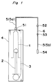
- Fig. 1 is a schematic view of a medical solution delivery system illustrating one embodiment of the present invention;
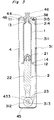
- Fig. 2 is a front view of the medical solution delivery system of Fig. 1;
- Fig. 3 is a vertical cross sectional view of the medical solution delivery system of Fig. 2;
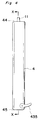
- Fig. 4 is a front view of a medical solution delivery system illustrating another embodiment of the present invention;
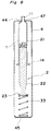
- Fig. 5 is a cross section view of the medical solution delivery system, taken along a line X-X in Fig. 4;
- Fig. 6 is a sectional view of a medical solution delivery system illustrating still another embodiment of the present invention;
- Fig. 7 is a sectional view of a medical solution delivery system illustrating still another embodiment of the present invention;
- Fig. 8 is a sectional view of a medical solution delivery system illustrating still another embodiment of the present invention.
- Referring now to Figs. 1 to 3, there is shown a medical solution delivery system embodying the present invention, which comprises a
cylindrical container 1, aplunger 2 slidably arranged therein, a plunger-driving means 3 for forcing theplunger 2 to move smoothly within thecontainer 1 towards the front end thereof, acapsule 4 for holding these components therein, and aconnecting tube 5 provided with a flow control means 6 arranged therein to control a flow rate of a medical solution. - The
container 1 is a cylindrical receptacle, usually made of glass or transparent synthetic resins such as polypropylene, polyester, poly(4-methylpentene-1), polycarbonate, and the like, having anopen end 12 and a closedend 13 having aport 11. - The
plunger 2 comprises aplunger rod 22 and agasket 21 mounted on a front end thereof. Theplunger rod 22 is usually made of glass or a synthetic resin such as polypropylene, polyethylene, polyester, polycarbonate, or the like. Theplunger rod 22 has aflange 23 formed on the rear end thereof as an integral part thereof. Thegasket 21 is usually made of butyl rubber or an olefin elastomer and used to seal an contacting area between theplunger 2 andcylindrical container 1 against leakage. - The
above container 1 and theplunger 2 combined therewith constitute a syringe or a plunger device for draw injecting or withdrawing medical solutions, similar to a well-known syringe. Thus, the plunger device in this embodiment may be replaced with a commercially available syringe. - The
capsule 4 is a cylindrical receptacle, usually made of a transparent material similar to that of thecylindrical container 1, having a closedend 45 at one end thereof and anarrow part 46 at the opposite end. As shown in Fig. 2, thecapsule 4 is divided into two parts, i.e., abody 42 and a coveringmember 41, along a parting line parallel to an axis of thecapsule 4 but spaced therefrom. The coveringmember 41 is removably attached to thecapsule body 42 by fitting it in the latter, but the former may be hinged to the latter. - The
capsule body 42 is provided with an L-shaped slit 431 extending from a middle part thereof along the barrel of thecapsule body 42 to the rear part and then circumferentially extending therefrom to form a short arm portion with acut 432. - The
body 42 of thecapsule 4 is provided with acylindrical projection 48 for engagement with thecontainer 1. Thisprojection 48 extends inwardly from an inside wall of thefront end 44 of thecapsule 4 and is communicated with thenarrow part 46 to allow thecontainer 1 to communicate with the connectingtube 5 through thenarrow part 11 thereof and thenarrow part 46 of the capsule. - The plunger-driving means 3 comprises a
constant force spring 31, such as CONSTON (Trademark of Sanko Hatsujo corporation). Thespring 31 is wound around adrum 312 at one end thereof and at theopposite end 314 fixed to an inside wall of thefront end 44 of thecapsule 4 by means of ascrew 38. To this end, the opposite end, i.e., front end of thespring 31 is bent at 314 and provided with ahole 315 through which thescrew 38 is engaged with the threaded bore formed in the inside wall of thefront end 44 of thecapsule 4. - The
drum 312 is provided with arod 433 constituting an operating means. Therod 433 is slidably arranged in the L-shaped guide slit 431 of thecapsule body 42 and adapted to be kept in thecut 432 before use. The wound part of theconstant force spring 31 comes into contact with the flanged rear end of theplunger 2 when therod 433 is released from thecut 432. - The connecting
tube 5 is separated into two parts, i.e., 5a and 5b by means of the flow control means 6. The connectingtube 5a is connected at one end thereof to thecylindrical container 1 by aconnector 51 and at the opposite end to one end of the flow control means 6 by aconnector 52, whereas the connectingtube 5b is connected at one end thereof to the opposite end of the flow control means 6 by aconnector 53 and at the other end to aconnector 54 used for attachment of a catheter (not illustrated in the drawings). However, the connectingtube 5 is unnecessarily required for the delivery system of the present invention. - The flow control means 6 may have any configuration depending on the time required for administration of a drug or an amount of a drug per unit time. Examples of preferred flow control means are those comprising a narrow tube provided with a very small bore as disclosed in Japanese patents JP-A-64-70069 or JP-A-H1-135359, or those comprising a pipe with a very small diameter as disclosed in Japanese patent specifications JP-A- 2-11159 or JP-A- 3-140163.
- To make the above medical solution delivery system ready for use, the
rod 433 removably fitted in thebore 313 of thedrum 312 is moved manually toward therear end 45 of thecapsule 4 along theguide slit 431 and the axis of thecapsule 4 until it reaches to the corner of theslit 431 as shown in Fig. 2, and then displaced laterally from the axis of thecapsule 4 to engage it with thecut 432 of the L-shaped slit 431. - Separate from the above, a medical solution to be transfused into a blood vessel of a patient is drawn into the plunger device composed of the
cylindrical container 1 and theplunger 2 in the same manner as that of the well-known syringe and then the plunger device is set in thecapsule 4, as shown in Fig. 3. Before of after setting the plunger device in thecapsule 4, thetube 5 is connected to thenarrow part 46 of thecapsule 4 at one end thereof and to a catheter at the opposite end by theconnector 54. In this case, the connectingtube 5 has been closed by a suitable closing means such as a clamp (not illustrated in the drawings). - After this, the closing means is removed form the tube to make a fluid communication between the cylindrical container and the catheter, and then the
rod 433 is released from thecut 432. For this reason, the wound part of theconstant force spring 31 comes into contact with the flanged rear end of theplunger 2 and theplunger 2 is applied with a constant force by theconstant force spring 31 so that it is forced to move towards the front end of thecylindrical container 1 until therod 433 reaches to the front end of the guide slit 431. During movement of theplunger 2, all the air present in thecontainer 1, thetube 5 and the catheter is expelled therefrom by the medical solution. - After the air being removed from the deliver system, the
tube 5 or the catheter is clamped by the clamping means. Then, the catheter is inserted into the blood vessel of a patient and therod 433 is pulled out from thebore 313 of thedrum 312. Then, the claimping means is removed form thetube 5 or the catheter, and theplunger 2 is forced again by theconstant force spring 31 to move towards the front end of thecontainer 1 so that the medical solution in thecontainer 1 is delivered therefrom through theport 11 and then injected into the blood vessel at the flow rate controlled by the flow control means 6. - In the embodiment of Fig. 1, the
container 1 is provided with aflange 14 like as a hypodermic syringe, but there is no need to provide such aflange 14 on the open end of thecontainer body 1, except for the case that the rear end of the cylindrical container is used for attachment of a free end of the plunger-driving means such as aconstant force spring 31, as shown in Fig. 5. - Referring now to Figs. 4 and 5, there is shown a modified form of a medical solution delivery system of the present invention. The medical solution delivery system in this embodiment comprises a syringe consisting of a
cylindrical container 1 and aplunger 2 slidably arranged therein; a plunger-driving means 3 for forcing theplunger 2 to move smoothly within thecylindrical container 1 towards the front end thereof; and aninseparable capsule 4 having a chamber for holding the syringe and a plunger-driving means 3. - In this embodiment, the
capsule 4 is composed of an inseparable cylindrical member and is provided at a front end thereof with ahole 47, through which a port ornarrow part 11 of thecylindrical container 1 is protruded outwardly from thecapsule 4, as shown in Fig. 5. - The plunger-driving means 3 comprises a pair of constant force springs 31, each of which is wound around a
drum 312 at one end thereof and fixed to a cylindrical fixingmember 35 at theopposite end 314 by means of ascrew 38. The fixingmember 35 is mounted on thecylindrical container 1. The wound part of the constant force springs 31 are held in adrum housing 36 fixed to theflange 23 of theplunger 2. Thedrum housing 36 is provided with a pair ofslits 363 though which aleading part 311 of eachspring 311 is stretched out to fix it to the fixingmember 35. - The
capsule 4 is provided at a rear part thereof with alever 435 so that thespring 31 can be displaced from the outside of thecapsule 4. Thelever 435 is adapted to be engaged with thedrum housing 36 to hold it in place during storage. In this case, thedrums 312 are redoubtably mounted on thedrum housing 36 by means of a shaft thereof. Thus, there is no need to provide an L-shaped guide slit in thecapsule 4. - In use, the
drum housing 36 is released from thelever 435 by turning it clockwise or counterclockwise after the delivery system is connected to a catheter through thetube 5 similar to that of Fig. 1. Theplunger 2 is forced to move towards the front end of thecylindrical container 1 by means of the constant force springs 31 and the medical solution previously filled in thecontainer 1 is injected into the blood vessel of a patient in the same manner as that in the embodiment of Fig. 1. - Fig. 6 shows another embodiment of a medical solution delivery system of the present invention. In this embodiment, the plunger-driving means 3 comprises two or
more rubber strings 32 in the form of a wire, which are arranged at a regular distance around a syringe composed of acylindrical container 1 and aplunger 2 and housed in acapsule 4. Thespring wire 32, usually made of natural rubber or a synthetic rubber such as isoprene rubber, butadiene rubber, is fixed at oneend 324 thereof to a rib on the side of thefront part 44 of thecapsule 4 and at the opposite end to adisk 34 which is adapted to come into contact with theflange 23 of theplunger 22. - To make this delivery system ready for use, the
disk 34 is moved manually toward therear end 45 of thecapsule 4 and then the syringe charged with a medical solution is set in thecapsule 4 so that theflange 32 comes into contact with thedisk 34. In this embodiment, it is therefore required to use a separable capsule similar to that used in the embodiment of Figs. 1 to 3. - As might be expected, the
capsule 4 used in the above embodiment may be provided with a spring-operating means similar to that used in the embodiment of Figs. 2 and 3. In this case, it is possible to use an inseparable capsule instead of theseparable capsule 4. - Figs. 7 and 8 show an embodiment of a medical solution delivery system employing a coil spring as a source of motive power for returning a displaced plunger to its original position. In the embodiment of Fig. 7, a
coil spring 33 is arranged around the syringe and fixed at one end 334 thereof to a rib formed in an inside wall of thecapsule 3 on the front side of thecapsule 4. The opposite end of thecoil spring 33 is fixed to the rear end of theplunger 2 by a suitable fixing means. The opposite end of thespring 33 may be fixed to a disk similar to that used in the embodiment of Fig. 6 as occasion demands. - The embodiment of Fig. 8 has a structure similar to that of the medical solution delivery system of Fig. 7 except for that a
coil spring 33 is arranged between theflange 22 of theplunger 2 and therear end wall 45 of thecapsule 4. - In case of that if the madulus or tensile stress of the rubber spring or coil spring, like as the embodiments of Fig. 6 or Fig. 7, is used for the plunger-driving means 3, it is preferred to minimize the difference between initial and final forces applied to the plunger as much as possible. It is therefore preferred to lengthen the stroke of the rubber spring wire or coil spring as much as possible. This may be done by fixing the front end of the spring to the inside of the
front end wall 44 of thecapsule 4. - As will be understood from the above, the medical solution delivery system of the present invention is simple in structure and small in the number of components. Thus, it is possible to provide inexpensive medical solution delivery systems. Also, the system is free from elution of chemical substances as the container is of glass or a polyolefine resin. By employing the constant force spring, it is possible to provide a medical solution delivery system capable of injecting a medical solution accurately at a well-controlled flow rate. Further, it is possible to inject the medical solution into the patient safely and certainly since the plunger is housed in the capsule along with the container and the plunger-driving means to prevent them from external influences such as, for example, pressures caused by movement of the body of the patient.
- Although the present invention has been fully described in connection with the preferred embodiments thereof with reference to the accompanying drawings, it is to be noted that various changes and modifications are apparent to those skilled in the art. Such changes and modifications are to be understood as included within the scope of the present invention as defined by the appended claims unless they depart therefrom.
Claims (10)
Applications Claiming Priority (2)
| Application Number | Priority Date | Filing Date | Title |
|---|---|---|---|
| JP4225252A JPH07509A (en) | 1992-07-31 | 1992-07-31 | Medicinal liquid injecting device |
| JP225252/92 | 1992-07-31 |
Publications (2)
| Publication Number | Publication Date |
|---|---|
| EP0584569A2 true EP0584569A2 (en) | 1994-03-02 |
| EP0584569A3 EP0584569A3 (en) | 1994-03-30 |
Family
ID=16826400
Family Applications (1)
| Application Number | Title | Priority Date | Filing Date |
|---|---|---|---|
| EP93112078A Withdrawn EP0584569A2 (en) | 1992-07-31 | 1993-07-28 | Medical solution delivery system |
Country Status (3)
| Country | Link |
|---|---|
| US (1) | US5380287A (en) |
| EP (1) | EP0584569A2 (en) |
| JP (1) | JPH07509A (en) |
Cited By (14)
| Publication number | Priority date | Publication date | Assignee | Title |
|---|---|---|---|---|
| WO1995024231A1 (en) * | 1994-03-09 | 1995-09-14 | I-Flow Corporation | Elastomeric syringe actuation device |
| FR2721828A1 (en) * | 1994-06-29 | 1996-01-05 | Siemens Elema Ab | DEVICE FOR BLEEDING A CATHETER FROM AN IMPLANTED INFUSION SYSTEM |
| US5599315A (en) * | 1995-12-01 | 1997-02-04 | Charles J. McPhee | Syringe actuation device |
| US5643213A (en) * | 1994-03-09 | 1997-07-01 | I-Flow Corporation | Elastomeric syringe actuation device |
| EP0836505A1 (en) * | 1995-06-06 | 1998-04-22 | Science Incorporated | Medicament dispenser |
| US5800405A (en) * | 1995-12-01 | 1998-09-01 | I-Flow Corporation | Syringe actuation device |
| EP0960626A3 (en) * | 1998-05-29 | 2000-01-19 | Fresenius AG | Implantable solution application device and actuator for a syringe for filling the device |
| US6019747A (en) * | 1997-10-21 | 2000-02-01 | I-Flow Corporation | Spring-actuated infusion syringe |
| US6712794B2 (en) | 2001-08-21 | 2004-03-30 | Spinal Specialties, Inc. | Apparatus for delivering a viscous liquid to a surgical site |
| EP1812096A2 (en) * | 2004-11-19 | 2007-08-01 | Curlin Medical Inc. | Controlled-volume infusion device |
| EP2265304A2 (en) * | 2008-04-11 | 2010-12-29 | Medtronic MiniMed, Inc. | Reservoir plunger head systems and methods |
| EP2898910A1 (en) * | 2014-01-24 | 2015-07-29 | Freddie Eng Hwee Lee | Elastic band powered fluid delivery apparatus |
| ITUB20154926A1 (en) * | 2015-10-30 | 2016-01-30 | Bcs S R L | Disposable syringe with automatic discharge device |
| WO2017089273A1 (en) * | 2015-11-27 | 2017-06-01 | Sanofi-Aventis Deutschland Gmbh | Medicament injection device |
Families Citing this family (45)
| Publication number | Priority date | Publication date | Assignee | Title |
|---|---|---|---|---|
| GB9611562D0 (en) * | 1996-06-03 | 1996-08-07 | Applied Research Systems | Device |
| US5779155A (en) * | 1996-11-26 | 1998-07-14 | The Procter & Gamble Company | Decoupled liquid delivery system |
| US7425209B2 (en) * | 1998-09-15 | 2008-09-16 | Baxter International Inc. | Sliding reconstitution device for a diluent container |
| US7358505B2 (en) * | 1998-09-15 | 2008-04-15 | Baxter International Inc. | Apparatus for fabricating a reconstitution assembly |
| JP3941088B2 (en) | 1999-09-20 | 2007-07-04 | ニプロ株式会社 | Chemical injection device |
| US20020172615A1 (en) * | 2001-03-08 | 2002-11-21 | Archie Woodworth | Apparatus for and method of manufacturing a prefilled sterile container |
| US7169128B2 (en) * | 2003-08-04 | 2007-01-30 | Bioquiddity, Inc. | Multichannel fluid delivery device |
| US7220244B2 (en) * | 2003-08-04 | 2007-05-22 | Bioquiddity, Inc. | Infusion apparatus with constant force spring energy source |
| US20050033232A1 (en) * | 2003-08-05 | 2005-02-10 | Kriesel Marshall S. | Infusion apparatus with modulated flow control |
| US20050133729A1 (en) * | 2003-12-23 | 2005-06-23 | Archie Woodworth | Apparatus and method for fabricating a reconstitution assembly |
| US7641851B2 (en) * | 2003-12-23 | 2010-01-05 | Baxter International Inc. | Method and apparatus for validation of sterilization process |
| US20050277884A1 (en) * | 2004-05-26 | 2005-12-15 | Kriesel Marshall S | Fluid delivery apparatus with bellows reservoir |
| US20070156090A1 (en) * | 2004-05-26 | 2007-07-05 | Kriesel Marshall S | Fluid delivery apparatus |
| US20050277883A1 (en) * | 2004-05-26 | 2005-12-15 | Kriesel Marshall S | Fluid delivery device |
| US7470253B2 (en) * | 2004-05-26 | 2008-12-30 | Bioquiddity, Inc. | Fluid delivery apparatus with adjustable flow rate control |
| US7220245B2 (en) * | 2004-05-26 | 2007-05-22 | Kriesel Marshall S | Infusion apparatus |
| DK1833536T3 (en) * | 2004-12-31 | 2020-07-20 | Tecpharma Licensing Ag | Coupling device for metered administration of a fluid product |
| US8029468B2 (en) * | 2005-02-15 | 2011-10-04 | Bioquiddity, Inc. | Fluid delivery and mixing apparatus with flow rate control |
| US7694938B2 (en) * | 2005-02-17 | 2010-04-13 | Bioquiddity, Inc. | Distal rate control device |
| US20080009835A1 (en) * | 2005-02-17 | 2008-01-10 | Kriesel Marshall S | Fluid dispensing apparatus with flow rate control |
| US7837653B2 (en) * | 2005-02-18 | 2010-11-23 | Bioquiddity, Inc. | Fluid delivery apparatus with vial fill |
| CA2598700A1 (en) * | 2005-02-24 | 2006-08-31 | Boston Scientific Santa Rosa Corporation | Constant force material delivery system and method |
| US7828772B2 (en) * | 2006-03-15 | 2010-11-09 | Bioquiddity, Inc. | Fluid dispensing device |
| US7993304B2 (en) * | 2006-03-15 | 2011-08-09 | Bioquiddity, Inc. | Fluid dispensing apparatus |
| US7867197B2 (en) * | 2006-03-29 | 2011-01-11 | The General Hospital Corporation | Single-dose syringe driver |
| US8057435B2 (en) | 2006-07-31 | 2011-11-15 | Kriesel Joshua W | Fluid dispenser |
| US8292848B2 (en) * | 2006-07-31 | 2012-10-23 | Bio Quiddity, Inc. | Fluid dispensing device with additive |
| US8968272B2 (en) | 2006-10-06 | 2015-03-03 | Lipocosm Llc | Closed system and method for atraumatic, low pressure, continuous harvesting, processing, and grafting of lipoaspirate |
| US20080243077A1 (en) * | 2007-04-02 | 2008-10-02 | Bivin Donald B | Fluid dispenser with uniformly collapsible reservoir |
| US20080319385A1 (en) * | 2007-06-25 | 2008-12-25 | Kriesel Marshall S | Fluid dispenser with additive sub-system |
| US8211059B2 (en) * | 2007-06-25 | 2012-07-03 | Kriesel Marshall S | Fluid dispenser with additive sub-system |
| US8083717B2 (en) * | 2008-09-03 | 2011-12-27 | Bioquiddity, Inc. | Two part fluid dispenser with twin reservoir |
| US20100056998A1 (en) * | 2008-09-03 | 2010-03-04 | Kriesel Marshall S | Two part fluid dispenser |
| US8622965B2 (en) * | 2008-09-03 | 2014-01-07 | Bioquiddity, Inc. | Two part fluid dispenser |
| US8480656B2 (en) * | 2008-09-03 | 2013-07-09 | Bioquiddity, Inc. | Two part fluid dispenser |
| US8100890B2 (en) * | 2008-10-15 | 2012-01-24 | Bioquiddity, Inc. | Special purpose fluid dispenser with pre-filled reservoir |
| CA2745621A1 (en) * | 2008-12-03 | 2011-06-02 | Denki Kagaku Kogyo Kabushiki Kaisha | Syringe |
| JP5428465B2 (en) * | 2009-03-31 | 2014-02-26 | パナソニック株式会社 | Syringe drive device |
| US8197445B2 (en) * | 2009-06-03 | 2012-06-12 | Bioquiddity, Inc. | Pain management dispenser |
| US8388571B2 (en) * | 2009-10-06 | 2013-03-05 | Bioquiddity, Inc. | Fluid dispenser with non-electric fluid heating component |
| US8821454B2 (en) | 2010-05-12 | 2014-09-02 | Bioquiddity, Inc. | Apparatus for dispensing medicinal fluids and method of making same |
| US9737659B2 (en) | 2010-05-12 | 2017-08-22 | Bioq Pharma Incorporated | Apparatus for dispensing medicinal fluids and method of making same |
| CA2901012C (en) * | 2013-02-15 | 2021-07-06 | Repro-Med Systems, Inc. | Multi-flow universal tubing set |
| JP2016013216A (en) * | 2014-07-01 | 2016-01-28 | 住友ベークライト株式会社 | Syringe operation aid and medical kit |
| US9669163B2 (en) | 2014-08-09 | 2017-06-06 | Bioq Pharma Incorporated | Apparatus for dispensing medicinal fluids and method of making same |
Citations (5)
| Publication number | Priority date | Publication date | Assignee | Title |
|---|---|---|---|---|
| US4298000A (en) * | 1978-11-08 | 1981-11-03 | Minnesota Mining And Manufacturing Company | Fluid dispensing device |
| US4381006A (en) * | 1980-11-10 | 1983-04-26 | Abbott Laboratories | Continuous low flow rate fluid dispenser |
| US4681566A (en) * | 1984-11-30 | 1987-07-21 | Strato Medical Corporation | Infusion device |
| EP0245056A1 (en) * | 1986-05-07 | 1987-11-11 | Vincent L. Vaillancourt | Ambulatory disposable infusion pump |
| US4755172A (en) * | 1987-06-30 | 1988-07-05 | Baldwin Brian E | Syringe holder/driver and syringe arrangement and syringe/holder driver therefor |
Family Cites Families (11)
| Publication number | Priority date | Publication date | Assignee | Title |
|---|---|---|---|---|
| US2725877A (en) * | 1950-12-22 | 1955-12-06 | Reiter David | Hypodermic syringe with feed control |
| US3895631A (en) * | 1974-02-04 | 1975-07-22 | Alza Corp | Liquid infusion unit |
| US4202333A (en) * | 1978-11-08 | 1980-05-13 | Minnesota Mining And Manufacturing Company | Fluid dispensing device |
| US4318400A (en) * | 1980-01-18 | 1982-03-09 | Alza Corporation | Medical infusor |
| US4863429A (en) * | 1987-06-30 | 1989-09-05 | Baldwin Brian E | Syringe driver/syringe/tube connecting set fluid delivery arrangement, and tube connecting sets therefor |
| ATA228987A (en) * | 1987-09-09 | 1993-07-15 | Pickhard Ewald | INJECTION DEVICE WITH A DEFORMABLE Vial |
| EP0425003A1 (en) * | 1989-10-24 | 1991-05-02 | Duphar International Research B.V | Training device for an automatic injector |
| US5105983A (en) * | 1989-10-31 | 1992-04-21 | Block Medical, Inc. | Infusion apparatus |
| US5080652A (en) * | 1989-10-31 | 1992-01-14 | Block Medical, Inc. | Infusion apparatus |
| JPH0451966A (en) * | 1990-06-19 | 1992-02-20 | Toichi Ishikawa | Medical fluid continuous injector |
| US5078679A (en) * | 1990-11-13 | 1992-01-07 | Reese H William | Post-surgical anesthesia at a continuous and progressively decreasing administration rate |
-
1992
- 1992-07-31 JP JP4225252A patent/JPH07509A/en active Pending
-
1993
- 1993-07-27 US US08/097,051 patent/US5380287A/en not_active Expired - Fee Related
- 1993-07-28 EP EP93112078A patent/EP0584569A2/en not_active Withdrawn
Patent Citations (5)
| Publication number | Priority date | Publication date | Assignee | Title |
|---|---|---|---|---|
| US4298000A (en) * | 1978-11-08 | 1981-11-03 | Minnesota Mining And Manufacturing Company | Fluid dispensing device |
| US4381006A (en) * | 1980-11-10 | 1983-04-26 | Abbott Laboratories | Continuous low flow rate fluid dispenser |
| US4681566A (en) * | 1984-11-30 | 1987-07-21 | Strato Medical Corporation | Infusion device |
| EP0245056A1 (en) * | 1986-05-07 | 1987-11-11 | Vincent L. Vaillancourt | Ambulatory disposable infusion pump |
| US4755172A (en) * | 1987-06-30 | 1988-07-05 | Baldwin Brian E | Syringe holder/driver and syringe arrangement and syringe/holder driver therefor |
Cited By (21)
| Publication number | Priority date | Publication date | Assignee | Title |
|---|---|---|---|---|
| US5643213A (en) * | 1994-03-09 | 1997-07-01 | I-Flow Corporation | Elastomeric syringe actuation device |
| TR28878A (en) * | 1994-03-09 | 1997-07-17 | I Flow Corp | Elastomeric syringa operating tool. |
| WO1995024231A1 (en) * | 1994-03-09 | 1995-09-14 | I-Flow Corporation | Elastomeric syringe actuation device |
| FR2721828A1 (en) * | 1994-06-29 | 1996-01-05 | Siemens Elema Ab | DEVICE FOR BLEEDING A CATHETER FROM AN IMPLANTED INFUSION SYSTEM |
| EP0836505A1 (en) * | 1995-06-06 | 1998-04-22 | Science Incorporated | Medicament dispenser |
| EP0836505A4 (en) * | 1995-06-06 | 2000-01-12 | Science Inc | Medicament dispenser |
| US5599315A (en) * | 1995-12-01 | 1997-02-04 | Charles J. McPhee | Syringe actuation device |
| US5800405A (en) * | 1995-12-01 | 1998-09-01 | I-Flow Corporation | Syringe actuation device |
| US6019747A (en) * | 1997-10-21 | 2000-02-01 | I-Flow Corporation | Spring-actuated infusion syringe |
| US6730060B1 (en) | 1998-05-29 | 2004-05-04 | Fresenius Medical Care Deutschland Gmbh | Implantable device for administering a treatment solution and operating device for a syringe for filling the device |
| EP0960626A3 (en) * | 1998-05-29 | 2000-01-19 | Fresenius AG | Implantable solution application device and actuator for a syringe for filling the device |
| US6712794B2 (en) | 2001-08-21 | 2004-03-30 | Spinal Specialties, Inc. | Apparatus for delivering a viscous liquid to a surgical site |
| EP1812096A2 (en) * | 2004-11-19 | 2007-08-01 | Curlin Medical Inc. | Controlled-volume infusion device |
| EP1812096A4 (en) * | 2004-11-19 | 2008-06-04 | Curlin Medical Inc | Controlled-volume infusion device |
| US8372045B2 (en) | 2004-11-19 | 2013-02-12 | Curlin Medical Inc. | Controlled-volume infusion device |
| EP2265304A2 (en) * | 2008-04-11 | 2010-12-29 | Medtronic MiniMed, Inc. | Reservoir plunger head systems and methods |
| EP2898910A1 (en) * | 2014-01-24 | 2015-07-29 | Freddie Eng Hwee Lee | Elastic band powered fluid delivery apparatus |
| CN105169514A (en) * | 2014-01-24 | 2015-12-23 | 弗雷迪·恩·辉·李 | Elastic Band Powered Fluid Delivery Apparatus |
| ITUB20154926A1 (en) * | 2015-10-30 | 2016-01-30 | Bcs S R L | Disposable syringe with automatic discharge device |
| WO2017089273A1 (en) * | 2015-11-27 | 2017-06-01 | Sanofi-Aventis Deutschland Gmbh | Medicament injection device |
| US11484662B2 (en) | 2015-11-27 | 2022-11-01 | Sanofi-Aventis Deutschland Gmbh | Medicament injection device |
Also Published As
| Publication number | Publication date |
|---|---|
| US5380287A (en) | 1995-01-10 |
| JPH07509A (en) | 1995-01-06 |
| EP0584569A3 (en) | 1994-03-30 |
Similar Documents
| Publication | Publication Date | Title |
|---|---|---|
| US5380287A (en) | Medical solution delivery system | |
| US10105494B2 (en) | Positive displacement flush syringe | |
| US3570484A (en) | Intravenous valve assembly | |
| US4059109A (en) | Mixing and dispensing disposable medicament injector | |
| US4553962A (en) | Medical syringe | |
| US8007475B2 (en) | Positive displacement flush syringe | |
| US4813937A (en) | Ambulatory disposable infusion delivery system | |
| JP4794463B2 (en) | Positive pressure flushing syringe | |
| US4758234A (en) | High viscosity fluid delivery system | |
| US5957895A (en) | Low-profile automatic injection device with self-emptying reservoir | |
| US4664655A (en) | High viscosity fluid delivery system | |
| US5858008A (en) | Cannula sealing shield assembly | |
| EP1946791B1 (en) | Indwelling needle | |
| US4116196A (en) | Additive adapter | |
| KR100312011B1 (en) | Filling device for a needleless injector cartridge | |
| US7682342B2 (en) | Syringe assembly | |
| US5713875A (en) | System for administration of a liquid agent to a patient with a syringe pump | |
| JPH0232898B2 (en) | ||
| JP3146469B2 (en) | Automatic syringe | |
| US4657533A (en) | Hypodermic injector device | |
| EP0584714A1 (en) | Medical solution delivery system | |
| EP3213793B1 (en) | Automatic anti-free-flow valve for medical pumps | |
| JPH0751367A (en) | Automatic syringe | |
| EP0245056A1 (en) | Ambulatory disposable infusion pump | |
| JP4096349B2 (en) | Chemical solution continuous injector |
Legal Events
| Date | Code | Title | Description |
|---|---|---|---|
| PUAI | Public reference made under article 153(3) epc to a published international application that has entered the european phase |
Free format text: ORIGINAL CODE: 0009012 |
|
| PUAL | Search report despatched |
Free format text: ORIGINAL CODE: 0009013 |
|
| AK | Designated contracting states |
Kind code of ref document: A2 Designated state(s): DE FR GB IT |
|
| AK | Designated contracting states |
Kind code of ref document: A3 Designated state(s): DE FR GB IT |
|
| 17P | Request for examination filed |
Effective date: 19940811 |
|
| 17Q | First examination report despatched |
Effective date: 19970204 |
|
| GRAG | Despatch of communication of intention to grant |
Free format text: ORIGINAL CODE: EPIDOS AGRA |
|
| GRAG | Despatch of communication of intention to grant |
Free format text: ORIGINAL CODE: EPIDOS AGRA |
|
| GRAG | Despatch of communication of intention to grant |
Free format text: ORIGINAL CODE: EPIDOS AGRA |
|
| GRAH | Despatch of communication of intention to grant a patent |
Free format text: ORIGINAL CODE: EPIDOS IGRA |
|
| STAA | Information on the status of an ep patent application or granted ep patent |
Free format text: STATUS: THE APPLICATION IS DEEMED TO BE WITHDRAWN |
|
| 18D | Application deemed to be withdrawn |
Effective date: 19990629 |