EP0585601A1 - Integrated circuit security system and method with implanted interconnections - Google Patents
Integrated circuit security system and method with implanted interconnections Download PDFInfo
- Publication number
- EP0585601A1 EP0585601A1 EP93111978A EP93111978A EP0585601A1 EP 0585601 A1 EP0585601 A1 EP 0585601A1 EP 93111978 A EP93111978 A EP 93111978A EP 93111978 A EP93111978 A EP 93111978A EP 0585601 A1 EP0585601 A1 EP 0585601A1
- Authority
- EP
- European Patent Office
- Prior art keywords
- doped
- interconnect
- regions
- circuit
- substrate
- Prior art date
- Legal status (The legal status is an assumption and is not a legal conclusion. Google has not performed a legal analysis and makes no representation as to the accuracy of the status listed.)
- Granted
Links
Images


Classifications
-
- H—ELECTRICITY
- H01—ELECTRIC ELEMENTS
- H01L—SEMICONDUCTOR DEVICES NOT COVERED BY CLASS H10
- H01L23/00—Details of semiconductor or other solid state devices
- H01L23/57—Protection from inspection, reverse engineering or tampering
- H01L23/573—Protection from inspection, reverse engineering or tampering using passive means
-
- G—PHYSICS
- G11—INFORMATION STORAGE
- G11C—STATIC STORES
- G11C7/00—Arrangements for writing information into, or reading information out from, a digital store
- G11C7/24—Memory cell safety or protection circuits, e.g. arrangements for preventing inadvertent reading or writing; Status cells; Test cells
-
- H—ELECTRICITY
- H01—ELECTRIC ELEMENTS
- H01L—SEMICONDUCTOR DEVICES NOT COVERED BY CLASS H10
- H01L27/00—Devices consisting of a plurality of semiconductor or other solid-state components formed in or on a common substrate
- H01L27/02—Devices consisting of a plurality of semiconductor or other solid-state components formed in or on a common substrate including semiconductor components specially adapted for rectifying, oscillating, amplifying or switching and having at least one potential-jump barrier or surface barrier; including integrated passive circuit elements with at least one potential-jump barrier or surface barrier
-
- H—ELECTRICITY
- H01—ELECTRIC ELEMENTS
- H01L—SEMICONDUCTOR DEVICES NOT COVERED BY CLASS H10
- H01L2924/00—Indexing scheme for arrangements or methods for connecting or disconnecting semiconductor or solid-state bodies as covered by H01L24/00
- H01L2924/0001—Technical content checked by a classifier
- H01L2924/0002—Not covered by any one of groups H01L24/00, H01L24/00 and H01L2224/00
Definitions
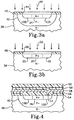
- FIGs. 3a and 3b are sectional views taken along the section lines 3a-3a and 3b-3b of FIG. 1b, respectively, illustrating the fabrication of the source, drain and interconnection implants, but excluding the polysilicon and metallization layers.
- the devices are formed in a semiconductor substrate 38 that for illustrative purposes is silicon, but may also be GaAs or some other desired semiconductor material.
- the circuit fabrication can be accomplished with a conventional process, such as that described in Frederiksen, Intuitive CMOS Electronics , McGraw-Hill Publishing Co., 1989, pages 134-145; it is a distinct advantage of the invention that it does not require any special processing to implement.
- the implantation can be performed exactly the same as in prior unsecured processes, the only difference being that the implant is now done through a larger opening in each mask that includes the implanted interconnection as well as the FET sources and drains. No differences in processing time or techniques are required, and the operator need not even know that the mask provides for circuit security.
- the circuits are then completed in a conventional manner, with threshold implants made into the FET channels to set the transistor characteristics.
- a field oxide is laid down as usual, but it also defines active areas which encompass "actual” as well as “possible” interconnect regions. Otherwise, the interconnect paths would be apparent.
- Polysilicon is then deposited and doped either by diffusion or ion implantation to form the channels and the interconnects.
- a dielectric is then deposited and metallization layers added to establish inputs, outputs and bias signals. Finally an overglass coating is laid down over the entire chip.
- a field oxide layer 54 insulates the FETs from adjacent devices, while the contact 14 to FET drain 12D is made from metallization layer 28 through an opening in an oxide insulating layer 56.
- oxide insulating layer 56 Several metallization layers separated by oxide layers are normally provided, although for simplicity only one metallization layer 28 is illustrated. This layer 28 is topped by a final oxide layer 58, and then a thicker overglass coating 60 of SiO2 that extends over the entire chip and is lightly doped so as to prevent the buildup of a static charge.
- FIG. 5 illustrates a three-input NAND gate that uses this approach; metallized connectors that are added at a later stage in the fabrication are not shown.
- the gate includes three p-channel FETs 62a, 62b and 62c, and three n-channel FETs 64a, 64b and 64c.
- Common polysilicon gate strips 66a, 66b and 66c are provided for transistor pairs 62a, 64a; 62b, 64b; and 62c, 64c, respectively.
- the polysilicon strips extend over the substrate surface between their respective FETs, as well as over the FET channels.
- To connect the upper FETs 62a-62c in parallel, their drains are electrically tied together by an interconnecting implant 60 in accordance with the invention.
- the secure NAND and NOR gates described herein and other types of logic gates can form the building blocks for many complicated logic sequences, which would therefore be virtually impossible to reverse engineer.
- a spreading resistance reverse engineering analysis might still theoretically be possible, with a small probe measuring the circuit's resistivity over a very small volume and stepped progressively across the surface, in practice this would also not work.
- the upper layers would have to be stripped away to analyze the implanted interconnects with the spreading resistance technique, but in so doing the positional registration of the implanted areas with respect to the stripped metallization would be lost.
- spreading resistance analysis is a mechanical process that is much slower than SEM analysis. The reverse engineer would still be able to see the transistors, but not the connections between them.
Abstract

Description
- This invention relates to the prevention of reverse engineering of integrated circuits (ICs), and more particularly to security techniques in which interconnections between circuit elements are made undetectable.
- Several techniques have been used to reverse engineer ICs. Electron (e)-beam probing with a scanning electron microscope (SEM), either through SEM photographs or voltage contrast analysis, is the standard reverse engineering mechanism, although secondary ion mass spectrometry (SIMS), spreading resistance analysis and various other techniques have also been used. A general description of e-beam probing is provided in Lee, "Engineering a Device for Electron-beam Probing", IEEE Design & Test of Computers, 1989, pages 36-49.
- Numerous ways to frustrate unwanted attempts to reverse engineer an IC have also been developed. For example, in Patent No. 4,766,516 to Ozdemir et al. (assigned to Hughes Aircraft Company, the assignee of the present invention), additional circuit elements that do not contribute toward the desired circuit function are added to an IC, and disguised with the visible appearance of being an ordinary part of the IC. The elements have physical modifications that are not readily visible but cause them to function in a different manner, inhibiting the proper functioning of the IC in case of an attempted copying or other unauthorized use. When the apparent function rather than the actual function of the disguised elements are copied, the resulting circuit will not operate properly.
- In Patent No. 4,583,011 to Pechar a pseudo-MOS (metal oxide semiconductor) device is given a depletion implant that is not readily visible to a copier, who would infer from the device's location in the circuit that it would be enhancement-mode. A somewhat related approach is taken in French patent publication no. 2 486 717 by Bassett et al., published January 15, 1982; the circuit doping is controlled so that some devices which appear to be transistors actually function as either open or short circuits. And in Patent No. 4,603,381 to Guttag the memory of a central processing unit is programmed by the doping of its channel regions, rather than by the presence or absence of gates, to protect permanently programmed software.
- Instead of disguising circuit elements, some systems have a mechanism to protect the circuit from operating until a correct access code has been entered. Such systems are described in Patent Nos. 4,139,864 to Schulman and 4,267,578 to Vetter.
- Each of the above protection schemes requires additional processing and/or uses additional circuitry that is dedicated to security and does not contribute to the basic functioning of the circuit. This increases the cost of circuit production and complicates the circuitry.
- The present invention seeks to provide a security system and method to protect against IC reverse engineering that is very difficult to detect, can be implemented without any additional fabrication steps and is compatible with computer added design (CAD) systems that allow many different kinds of logic circuits to be constructed with ease.
- A logic gate is formed in a semiconductor substrate in accordance with the invention by forming doped regions in the substrate of like conductivity, and interconnecting at least some of the like conductivity regions by similarly doping interconnect portions of the substrate that run between such regions. The interconnects and the regions they connect are preferably doped simultaneously through a common dopant implantation mask to similar dopant concentrations, resulting in an integral structure for the doped regions and their interconnects. Metallized interconnects are provided as needed between p- and n- doped regions, and metallic microbridges can be used to span strips of polycrystalline gate material that interrupt an interconnect circuit. A metallized interconnect can also be formed above the substrate to further mask a doped interconnect from observation.
- Although doped implants are generally not as highly conductive as metallized interconnects, their resistance is low enough to serve an interconnect function at very large scale integration (VLSI) dimensions. Because the implanted connections are not visible to SEM or optical viewing technique, the purpose or function of the logic gates cannot be deduced, thus making the circuit very difficult to reverse engineer. Many different circuit designs that use the security technique can be stored in a CAD library and readily recalled for use as desired.
- Further features and advantages of the invention will be apparent to those skilled in the art from the following detailed description, taken together with the accompanying drawings.
-
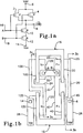
- FIGs. 1a and 1b are respectively a schematic diagram and a plan view of a NAND gate in accordance with the invention;
- FIGs. 2a and 2b are respectively a schematic diagram and a plan view of a NOR gate in accordance with the invention;
- FIGs. 3a and 3b are sectional views taken along
section lines 3a-3a and 3b-3b of FIG. 1b that illustrate the simultaneous formation of transistor source/drain regions and implanted interconnects therebetween with a common implant process and common masks for n-channel and p-channel transistors, respectively; - FIG. 4 is a sectional view taken along section line 404 in FIG. 2b of interconnected source/drain regions in accordance with the invention, with the implanted interconnect shaded by an upper metallization layer;
- FIG. 5 is a simplified plan view of a logic gate that uses metallized microbridges to span polycrystalline gate layers in accordance with the invention; and
- FIG. 6 is a sectional view of a microbridge span.
- An important aspect of this invention is that it does not rely upon any modifications or additions to the functioning of the circuitry that is to be protected from reverse engineering, nor does it require any additional processing steps or equipment. Instead, a highly effective deterrent to reverse engineering is accomplished in a streamlined manner that adds neither cost, time nor complexity to the basic circuitry.
- Implementations of the invention in the form of NAND and NOR gates will first be described. Using such gates as building blocks, many different types of logic circuitry can be designed. A distinct advantage of the invention is that different types of logic circuits may be made to look alike, thus confusing a potential reverse engineer.
- FIG. 1a is a schematic diagram of a conventional two-input NAND gate circuit, with a pair of p-
channel transistors output terminal 8, and a pair of n-channel transistors negative voltage terminal 14 and theoutput terminal 8.Input terminals - An implementation of this basic logic gate in accordance with the invention is shown in FIG. 1b. The sources, drains and gates of each of the transistors are indicated by the same transistor numbers as in FIG. 1, followed by S, D or G, respectively. The transistor sources and drains (the designation of an element as a source or drain is somewhat arbitrary) are fabricated in a conventional manner by implanting dopant ions into the circuit substrate. The p+ sources and drains of the p-
channel devices channel transistors - Rather than connecting the transistor regions of like conductivity with metallized interconnects in the conventional fashion, such connections are made by means of doping implants into the substrate between the desired sources and drains. Three
such interconnections sources drains drain 10D-source 12S, respectively. The implant interconnections are preferably established simultaneously with the source and drain implants by providing appropriate openings in the implantation mask (if flood beam implantation is employed), or by extending the scanning area of a focused ion beam. As an alternate to implantation a conventional gaseous diffusion process could be employed to establish the doping, but this is less preferable than implantation. By using the same source/drain fabrication step to also fabricate the implanted interconnections, the interconnections have the same dopant concentration as the sources and drains and are formed integrally therewith. - The remainder of the gate circuit is fabricated in a conventional manner. The polysilicon gates (assuming a silicon substrate is used) can be formed either before or after the source and drain and interconnect implants, while
metallized connectors Vss terminal 14 andoutput terminal 8. - FIG. 2a is a schematic diagram of a conventional NOR gate, while FIG. 2b illustrates its implementation in accordance with the invention. It uses the same transistor layout as the NAND gate of FIGs. 1a and 1b, but the implanted interconnects between the transistors of like conductivity is reversed. Specifically, p-
channel transistors output terminal 8 by a p-dopedimplant 32 that runs betweendrain 4D oftransistor 4 andsource 2S oftransistor 2; the n-channel transistors negative voltage terminal 14 andoutput terminal 8 by n-doped implant interconnects 34 and 36 between the sources and gates oftransistors - FIGs. 3a and 3b are sectional views taken along the
section lines 3a-3a and 3b-3b of FIG. 1b, respectively, illustrating the fabrication of the source, drain and interconnection implants, but excluding the polysilicon and metallization layers. The devices are formed in asemiconductor substrate 38 that for illustrative purposes is silicon, but may also be GaAs or some other desired semiconductor material. The circuit fabrication can be accomplished with a conventional process, such as that described in Frederiksen, Intuitive CMOS Electronics, McGraw-Hill Publishing Co., 1989, pages 134-145; it is a distinct advantage of the invention that it does not require any special processing to implement. - In a typical CMOS process, a protective oxide layer about 250 Angstroms thick is first laid down over the
semiconductor substrate 38. A well is then implanted through openings in the oxide layer for each FET whose source and drain is of the same conductivity type as the substrate doping. Withsubstrate 38 illustrated as having an n- doping, a somewhat more heavily doped p-well 40 would be implanted about 3 microns deep for the n-channel devices (FIG. 3a). The wells are then subjected to a long, high temperature anneal, typically at about 1,150° C for about 10 hours. - The next step is the FET source and drain implants. For the n-channel devices an
oxide mask 42 is laid down over the substrate with openings at the desired locations for the sources and drains of the n-channel devices. In the case of two n-channel FETs continuous mask opening 44 is provided for thedrain 10D ofFET 10, thesource 12S ofFET 12, and theinterconnection implant 24 that runs between them. The implantation is then formed, preferably with a flood beam indicated by numeral 46, of suitable n-dopant ions such as arsenic. - As in conventional processing, a
separate implant mask 48 is provided for the p-channel devices (FIG. 3b). A single continuous opening 50 is provided in the mask for each interconnection implant and the transistor elements which they connect; these are illustrated as p-channel FET sources interconnect implant 20. Implantation is preferably performed with a flood beam, indicated bynumeral 52, of a suitable p-type dopant such as boron. - The implantation can be performed exactly the same as in prior unsecured processes, the only difference being that the implant is now done through a larger opening in each mask that includes the implanted interconnection as well as the FET sources and drains. No differences in processing time or techniques are required, and the operator need not even know that the mask provides for circuit security. The circuits are then completed in a conventional manner, with threshold implants made into the FET channels to set the transistor characteristics. A field oxide is laid down as usual, but it also defines active areas which encompass "actual" as well as "possible" interconnect regions. Otherwise, the interconnect paths would be apparent. Polysilicon is then deposited and doped either by diffusion or ion implantation to form the channels and the interconnects. A dielectric is then deposited and metallization layers added to establish inputs, outputs and bias signals. Finally an overglass coating is laid down over the entire chip.
- The implant interconnections have been demonstrated to be virtually invisible to SEM scanning in a secondary electron mode. They are also believed to be invisible to a voltage contrast SEM analysis. However, to guard against the possibility of their being detected through voltage contrast, the upper metallization can be designed to mask the implants. Thus, voltage contrast analysis of the interconnect implantations cannot be performed until the upper metallization layers are stripped away to expose the implants, but if the upper metallization is removed the voltage contrast analysis cannot be performed because there is no longer a mechanism for applying a voltage to the implant; the metallization that must be removed to expose the implants provided this function. Such a structure is illustrated in FIG. 4, which shows a sectional view of FET drains 10D and 12D and their
interconnect implant 36 from FIG. 2b, after the circuit fabrication has been completed. The structure employs a p-well process; a corresponding structure would result from an n-well process. Afield oxide layer 54 insulates the FETs from adjacent devices, while thecontact 14 toFET drain 12D is made frommetallization layer 28 through an opening in anoxide insulating layer 56. Several metallization layers separated by oxide layers are normally provided, although for simplicity only onemetallization layer 28 is illustrated. Thislayer 28 is topped by afinal oxide layer 58, and then athicker overglass coating 60 of SiO₂ that extends over the entire chip and is lightly doped so as to prevent the buildup of a static charge. - While the implanted interconnections described thus far can successfully connect different FETs, having them pass under strips of polysilicon that extend along the substrate surface should be avoided. This is because the polysilicon is biased to function as a gate, and when crossing over an implanted interconnection would in effect establish a transistor at that location. To avoid this, metal microbridges can be used to span polysilicon strips. Microbridges are known elements that are described, for example, in U.S. Patent Nos. 4,239,312 and 4,275,410, assigned to Hughes Aircraft Company.
- FIG. 5 illustrates a three-input NAND gate that uses this approach; metallized connectors that are added at a later stage in the fabrication are not shown. The gate includes three p-
channel FETs channel FETs 64a, 64b and 64c. Common polysilicon gate strips 66a, 66b and 66c are provided fortransistor pairs upper FETs 62a-62c in parallel, their drains are electrically tied together by an interconnectingimplant 60 in accordance with the invention. However, a corresponding interconnection cannot be made between their sources, since it would have to cross thepolysilicon gate strip microbridges additional microbridge 68a is shown spanningpolysilicon strip 66a between theFET 62a source extension and anisland 70 that is implanted into the substrate along with the FET sources, drains and interconnects. This bridge can either serve a dummy purpose to confuse a reverse engineer, orisland 70 can provide a contact point to receive a signal from an upper metallization for transmission to the sources ofFETs 62a-62c. - The
lower FETs 64a-64c can be connected in series directly with implantedinterconnects FET 64a and the drain of FET 64b, and the source of 64b and drain of 64c, since there are no polysilicon strips in the paths of these connections. However, an implanted source extension of FET 64c is shown connected to animplant island 74a above the drain ofFET 64a via a series of implanted islands 74b and 74c andmicrobridges polysilicon strips 64a, 64b and 64c, respectively. These microbridges can also either serve a dummy purpose, or be used to transmit a signal between a metallized connection toisland 74a and the drain of FET 64c. - FIG. 6 is a simplified sectional view of
microbridge 68a and its interconnection with the circuitry. One leg of the microbridge contacts the upper surface of p-dopedimplant island 70, while the opposite leg contacts the p-doped implant interconnection betweenFETs polysilicon strip 66a, with an insulatingdielectric 78 between the two elements. - By replacing metal interconnects with implanted interconnections that are not visible to SEM or optical viewing techniques, the purpose or function of the protected circuits cannot be deduced by a reverse engineer. Furthermore, it will be difficult for the reverse engineer to determine when the circuits are covertly connected by etching all metal, oxide and nitride layers deposited later in the fabrication process, because with the dimensions employed for modern VLSI circuits normal dying, ion milling, ion spectroscopy and SIMS techniques do not have the required sensitivity.
- The secure NAND and NOR gates described herein and other types of logic gates can form the building blocks for many complicated logic sequences, which would therefore be virtually impossible to reverse engineer. Although a spreading resistance reverse engineering analysis might still theoretically be possible, with a small probe measuring the circuit's resistivity over a very small volume and stepped progressively across the surface, in practice this would also not work. The upper layers would have to be stripped away to analyze the implanted interconnects with the spreading resistance technique, but in so doing the positional registration of the implanted areas with respect to the stripped metallization would be lost. Furthermore, spreading resistance analysis is a mechanical process that is much slower than SEM analysis. The reverse engineer would still be able to see the transistors, but not the connections between them.
- Since the only required change in the fabrication process is for a modification in the openings of the ion implantation masks, a new set of standard masks with the modified openings could be provided and used as standard elements of the circuit design process. This makes the invention particular suitable to CAD systems, with the designer simply selecting a desired secured logic gate design from a library of such gates.
- While several illustrative embodiments of the invention have been shown and described, numerous variations and alternate embodiments will occur to those skilled in the art. Such variations and alternate embodiments are contemplated, and can be made without departing from the spirit and scope of the invention as defined in the appended claims.
Claims (16)
- A secure integrated circuit (IC), comprising:
a semiconductor substrate (38),
a plurality of doped IC elements (2, 4, 10, 12; 62, 64) formed in said substrate (38), and
an interconnect (20, 22, 24; 32, 34, 36; 60, 70, 72, 74) for at least one of said elements (2, 4, 10, 12; 62, 64),
characterized in that said interconnect (20, 22, 24; 32, 34, 36; 60, 70, 72, 74) comprises a dopant implant (20, 22, 24; 32, 34, 36; 60, 70, 72, 74) in said substrate (38) of like conductivity to said element (2, 4, 10, 12; 62, 64), and provides an electrical signal path to interconnect said element (2, 4, 10, 12; 62, 64) with another portion of the IC. - The circuit of claim 1, characterized in that at least one element (2, 4, 10, 12; 62, 64) and said interconnect (20, 22, 24; 32, 34, 36; 60, 70, 72, 74) have similar dopant concentrations.
- A secure integrated circuit (IC) logic circuit, comprising:
a semiconductor substrate (38), and
a logic gate formed in said substrate with doped regions (2S, 4S; 2D, 4D; 10D, 12S; 2S, 4D; 10S, 12S; 10D, 12D; 62a, 62b, 62c; 64a, 64b, 64c) of like conductivity, and a doped interconnect (20, 22, 24; 32, 34, 36; 60, 70, 72, 74) implant in said substrate (38) of like conductivity to said doped regions (2S, 4S; 2D, 4D; 10D, 12S; 2S, 4D; 10S, 12S; 10D, 12D; 62a, 62b, 62c; 64a, 64b, 64c) and electrically interconnecting said regions (2S, 4S; 2D, 4D; 10D, 12S; 2S, 4D; 10S, 12S; 10D, 12D; 62a, 62b, 62c; 64a, 64b, 64c). - The circuit of claim 3, characterized in that said doped regions (2S, 4S; 2D, 4D; 10D, 12S; 2S, 4D; 10S, 12S; 10D, 12D; 62a, 62b, 62c; 64a, 64b, 64c) and interconnect implant (20, 22, 24; 32, 34, 36; 60, 70, 72, 74) have similar dopant concentrations.
- The circuit of claim 4, characterized in that the doping of said doped regions (2S, 4S; 2D, 4D; 10D, 12S; 2S, 4D; 10S, 12S; 10D, 12D; 62a, 62b, 62c; 64a, 64b, 64c) are integral with the doping of said interconnect implant (20, 22, 24; 32, 34, 36; 60, 70, 72, 74).
- The circuit of any of claims 3-5, characterized in that said logic gate has p- (2S, 4S; 2D, 4D; 62a, 62b, 62c) and n-doped (10D, 12D; 10S, 12S; 64a, 64b, 64c) regions, with a p-doped interconnection implant (20, 22, 60) interconnecting p-doped regions (2S, 4S; 2D, 4D; 62a, 62b, 62c), an n-doped interconnection implant (24, 72) interconnecting n-doped regions (10D, 12D; 10S, 12S; 64a, 64b, 64c), and a metallization connector (30) interconnecting p- and n-doped regions (2S, 4S; 2D, 4D; 10D, 12S; 2S, 4D; 10S, 12S; 10D, 12D; 62a, 62b, 62c; 64a, 64b, 64c).
- The circuit of claim 6, characterized in that said logic gate comprises a complementary metal oxide semiconductor (CMOS) gate.
- The circuit of any of claims 3-7, characterized in that said logic gate comprises a NAND gate with a pair of n-doped metal oxide semiconductor field effect transistors (MOSFETs) (10, 12, 64) connected in series by an n-doped interconnect (24, 72) between a first voltage reference (Vss) and an output (8), a pair of p-doped MOSFETs (2, 4, 62) connected in parallel by a p-doped interconnect (20, 22, 60) between a second voltage reference (Vdd) and said output (8), metallized connectors (28, 26) for said first and second voltage references (Vss, Vdd), and a metallized output connector (30).
- The circuit of any of claims 3-7, characterized in that said logic gate comprises a NOR gate with a pair of p-doped metal oxide semiconductor field effect transistors (MOSFETs) (2, 4) connected in series by a p-doped interconnect (32) between a first voltage reference (Vdd) and an output (8), a pair of n-doped MOSFETs (10, 12) connected in parallel by an n-doped interconnect (34, 36) between a second voltage reference (Vss) and said output (8), metallized connectors (26, 28) for said first and second voltage references (Vss, Vdd), and a metallized output connector (30).
- The circuit of any of claims 1-9, characterized in that it further comprises a metallization (28) above said substrate (38) masking said interconnect (20, 22, 24; 32, 34, 36; 60, 70, 72, 74) from external observation.
- The circuit of any-of claims 1-10, characterized in that said logic gate includes a pair of said doped interconnects (70, 74a, 74b, 74c) of like conductivity separated by a strip of polycrystalline substrate material (66a, 66b, 66c) on said substrate (38), and a metallic micro bridge (68a, 68b, 68c; 76a, 76b, 76c) spanning said strip of polycrystalline material (66a, 66b, 66c) and connecting said doped interconnects (70, 74a, 74b, 74c).
- A method of fabricating an integrated circuit (IC), comprising:
forming IC elements in a semiconductor substrate (38) with doped regions (2S, 4S; 2D, 4D; 10D, 12S; 2S, 4D; 10S, 12S; 10D, 12D; 62a, 62b, 62c; 64a, 64b, 64c) that have like conductivity, and
interconnecting at least some of said like conductivity doped regions (2S, 4S; 2D, 4D; 10D, 12S; 2S, 4D; 10S, 12S; 10D, 12D; 62a, 62b, 62c; 64a, 64b, 64c) by doping interconnect portions (20, 22, 24; 32, 34, 36; 60, 70, 72, 74) of said substrate (38) between said regions (2S, 4S; 2D, 4D; 10D, 12S; 2S, 4D; 10S, 12S; 10D, 12D; 62a, 62b, 62c; 64a, 64b, 64c) to a like conductivity with said regions (2S, 4S; 2D, 4D; 10D, 12S; 2S, 4D; 10S, 12S; 10D, 12D; 62a, 62b, 62c; 64a, 64b, 64c). - The method of claim 12, characterized in that said interconnect portions (20, 22, 24; 32, 34, 36; 60, 70, 72, 74) of said substrate (38) are doped to a similar dopant concentration as the dopant concentrations of the regions (2S, 4S; 2D, 4D; 10D, 12S; 2S, 4D; 10S, 12S; 10D, 12D; 62a, 62b, 62c; 64a, 64b, 64c) they interconnect.
- The method of claim 12 or 13, characterized in that said interconnect portions (20, 22, 24; 32, 34, 36; 60, 70, 72, 74) are formed integrally with the doped regions (2S, 4S; 2D, 4D; 10D, 12S; 2S, 4D; 10S, 12S; 10D, 12D; 62a, 62b, 62c; 64a, 64b, 64c) they interconnect.
- The method of any of claims 12-14, characterized in that said interconnect portions (20, 22, 24; 32, 34, 36; 60, 70, 72, 74) and the regions (2S, 4S; 2D, 4D; 10D, 12S; 2S, 4D; 10S, 12S; 10D, 12D; 62a, 62b, 62c; 64a, 64b, 64c) they interconnect are doped simultaneously.
- The method of any of claims 12-15, characterized in that said interconnect portions (20, 22, 24; 32, 34, 36; 60, 70, 72, 74) and the regions (2S, 4S; 2D, 4D; 10D, 12S; 2S, 4D; 10S, 12S; 10D, 12D; 62a, 62b, 62c; 64a, 64b, 64c) they interconnect are doped through a common dopant implantation mask (42, 48).
Priority Applications (1)
| Application Number | Priority Date | Filing Date | Title |
|---|---|---|---|
| EP98119897A EP0940851B1 (en) | 1992-07-31 | 1993-07-28 | Integrated circuit security system and method with implanted interconnections |
Applications Claiming Priority (2)
| Application Number | Priority Date | Filing Date | Title |
|---|---|---|---|
| US92341192A | 1992-07-31 | 1992-07-31 | |
| US923411 | 1992-07-31 |
Related Child Applications (1)
| Application Number | Title | Priority Date | Filing Date |
|---|---|---|---|
| EP98119897A Division EP0940851B1 (en) | 1992-07-31 | 1993-07-28 | Integrated circuit security system and method with implanted interconnections |
Publications (2)
| Publication Number | Publication Date |
|---|---|
| EP0585601A1 true EP0585601A1 (en) | 1994-03-09 |
| EP0585601B1 EP0585601B1 (en) | 1999-04-28 |
Family
ID=25448650
Family Applications (2)
| Application Number | Title | Priority Date | Filing Date |
|---|---|---|---|
| EP98119897A Expired - Lifetime EP0940851B1 (en) | 1992-07-31 | 1993-07-28 | Integrated circuit security system and method with implanted interconnections |
| EP93111978A Expired - Lifetime EP0585601B1 (en) | 1992-07-31 | 1993-07-28 | Integrated circuit security system and method with implanted interconnections |
Family Applications Before (1)
| Application Number | Title | Priority Date | Filing Date |
|---|---|---|---|
| EP98119897A Expired - Lifetime EP0940851B1 (en) | 1992-07-31 | 1993-07-28 | Integrated circuit security system and method with implanted interconnections |
Country Status (5)
| Country | Link |
|---|---|
| US (3) | US5866933A (en) |
| EP (2) | EP0940851B1 (en) |
| JP (1) | JPH06163539A (en) |
| DE (2) | DE69333881T2 (en) |
| IL (1) | IL106513A (en) |
Cited By (14)
| Publication number | Priority date | Publication date | Assignee | Title |
|---|---|---|---|---|
| EP0764985A2 (en) | 1995-09-22 | 1997-03-26 | Hughes Aircraft Company | Digital circuit with transistor geometry and channel stops providing camouflage against reverse engineering |
| EP0803702A2 (en) * | 1996-04-25 | 1997-10-29 | Hewlett-Packard Company | Micro needle probe apparatus |
| EP0883184A2 (en) * | 1997-06-06 | 1998-12-09 | Hughes Electronics Corporation | Camouflaged circuit structure with implants |
| EP0948052A2 (en) * | 1998-03-12 | 1999-10-06 | Philips Patentverwaltung GmbH | Microcontroller device |
| WO2000028593A1 (en) * | 1998-11-11 | 2000-05-18 | Infineon Technologies Ag | Method for producing a semiconductor component with wiring partly extending in the substrate and semiconductor component produced according to said method |
| US6667245B2 (en) | 1999-11-10 | 2003-12-23 | Hrl Laboratories, Llc | CMOS-compatible MEM switches and method of making |
| US6740942B2 (en) | 2001-06-15 | 2004-05-25 | Hrl Laboratories, Llc. | Permanently on transistor implemented using a double polysilicon layer CMOS process with buried contact |
| US6774413B2 (en) | 2001-06-15 | 2004-08-10 | Hrl Laboratories, Llc | Integrated circuit structure with programmable connector/isolator |
| US6791191B2 (en) | 2001-01-24 | 2004-09-14 | Hrl Laboratories, Llc | Integrated circuits protected against reverse engineering and method for fabricating the same using vias without metal terminations |
| US6815816B1 (en) | 2000-10-25 | 2004-11-09 | Hrl Laboratories, Llc | Implanted hidden interconnections in a semiconductor device for preventing reverse engineering |
| US7732321B2 (en) | 2004-05-17 | 2010-06-08 | Nds Limited | Method for shielding integrated circuits |
| US7888213B2 (en) | 2002-09-27 | 2011-02-15 | Hrl Laboratories, Llc | Conductive channel pseudo block process and circuit to inhibit reverse engineering |
| US7935603B1 (en) | 2004-06-29 | 2011-05-03 | Hrl Laboratories, Llc | Symmetric non-intrusive and covert technique to render a transistor permanently non-operable |
| US8679908B1 (en) | 2002-11-22 | 2014-03-25 | Hrl Laboratories, Llc | Use of silicide block process to camouflage a false transistor |
Families Citing this family (45)
| Publication number | Priority date | Publication date | Assignee | Title |
|---|---|---|---|---|
| EP0940851B1 (en) * | 1992-07-31 | 2005-10-05 | Hughes Electronics Corporation | Integrated circuit security system and method with implanted interconnections |
| JP3405508B2 (en) * | 1997-05-30 | 2003-05-12 | 富士通株式会社 | Semiconductor integrated circuit |
| US6096580A (en) * | 1999-09-24 | 2000-08-01 | International Business Machines Corporation | Low programming voltage anti-fuse |
| US6275072B1 (en) * | 1999-10-07 | 2001-08-14 | Velio Communications, Inc. | Combined phase comparator and charge pump circuit |
| US6515304B1 (en) | 2000-06-23 | 2003-02-04 | International Business Machines Corporation | Device for defeating reverse engineering of integrated circuits by optical means |
| JP4794030B2 (en) * | 2000-07-10 | 2011-10-12 | ルネサスエレクトロニクス株式会社 | Semiconductor device |
| US7217977B2 (en) * | 2004-04-19 | 2007-05-15 | Hrl Laboratories, Llc | Covert transformation of transistor properties as a circuit protection method |
| US7294935B2 (en) * | 2001-01-24 | 2007-11-13 | Hrl Laboratories, Llc | Integrated circuits protected against reverse engineering and method for fabricating the same using an apparent metal contact line terminating on field oxide |
| JP4899248B2 (en) * | 2001-04-02 | 2012-03-21 | 富士通セミコンダクター株式会社 | Semiconductor integrated circuit |
| US6459629B1 (en) | 2001-05-03 | 2002-10-01 | Hrl Laboratories, Llc | Memory with a bit line block and/or a word line block for preventing reverse engineering |
| US6897535B2 (en) | 2002-05-14 | 2005-05-24 | Hrl Laboratories, Llc | Integrated circuit with reverse engineering protection |
| US6924552B2 (en) * | 2002-10-21 | 2005-08-02 | Hrl Laboratories, Llc | Multilayered integrated circuit with extraneous conductive traces |
| AU2003293540A1 (en) * | 2002-12-13 | 2004-07-09 | Raytheon Company | Integrated circuit modification using well implants |
| EP2048708B1 (en) * | 2003-02-04 | 2011-01-12 | Panasonic Corporation | Semiconductor integrated circuit device |
| JP2007528121A (en) * | 2003-07-11 | 2007-10-04 | コーニンクレッカ フィリップス エレクトロニクス エヌ ヴィ | Semiconductor products that require confidentiality, especially smart card chips |
| FR2865827A1 (en) * | 2004-01-29 | 2005-08-05 | St Microelectronics Sa | SECURING THE TEST MODE OF AN INTEGRATED CIRCUIT |
| US8296577B2 (en) * | 2004-06-08 | 2012-10-23 | Hrl Laboratories, Llc | Cryptographic bus architecture for the prevention of differential power analysis |
| US8247840B2 (en) * | 2004-07-07 | 2012-08-21 | Semi Solutions, Llc | Apparatus and method for improved leakage current of silicon on insulator transistors using a forward biased diode |
| US7683433B2 (en) * | 2004-07-07 | 2010-03-23 | Semi Solution, Llc | Apparatus and method for improving drive-strength and leakage of deep submicron MOS transistors |
| US7375402B2 (en) * | 2004-07-07 | 2008-05-20 | Semi Solutions, Llc | Method and apparatus for increasing stability of MOS memory cells |
| US7224205B2 (en) * | 2004-07-07 | 2007-05-29 | Semi Solutions, Llc | Apparatus and method for improving drive-strength and leakage of deep submicron MOS transistors |
| US7651905B2 (en) * | 2005-01-12 | 2010-01-26 | Semi Solutions, Llc | Apparatus and method for reducing gate leakage in deep sub-micron MOS transistors using semi-rectifying contacts |
| US7898297B2 (en) * | 2005-01-04 | 2011-03-01 | Semi Solution, Llc | Method and apparatus for dynamic threshold voltage control of MOS transistors in dynamic logic circuits |
| DE102005028905A1 (en) * | 2005-06-22 | 2006-12-28 | Infineon Technologies Ag | Transistor component for complementary MOS logic circuit, has substrate connecting contact arranged in substrate connecting region for conductively connecting substrate connecting region to supply voltage lead |
| FR2897439A1 (en) * | 2006-02-15 | 2007-08-17 | St Microelectronics Sa | Electronic circuit, has set of configuration cells forming linear feedback shift register, and connection and combination unit for connecting data inputs to data output of connection cell when authentication signal is in active state |
| US7863689B2 (en) * | 2006-09-19 | 2011-01-04 | Semi Solutions, Llc. | Apparatus for using a well current source to effect a dynamic threshold voltage of a MOS transistor |
| US8168487B2 (en) | 2006-09-28 | 2012-05-01 | Hrl Laboratories, Llc | Programmable connection and isolation of active regions in an integrated circuit using ambiguous features to confuse a reverse engineer |
| US7994042B2 (en) * | 2007-10-26 | 2011-08-09 | International Business Machines Corporation | Techniques for impeding reverse engineering |
| US7709401B2 (en) * | 2008-02-22 | 2010-05-04 | International Business Machines Corporation | Method of making thermally programmable anti-reverse engineering interconnects wherein interconnects only conduct when heated above room temperature |
| US8418091B2 (en) * | 2009-02-24 | 2013-04-09 | Syphermedia International, Inc. | Method and apparatus for camouflaging a standard cell based integrated circuit |
| US8510700B2 (en) | 2009-02-24 | 2013-08-13 | Syphermedia International, Inc. | Method and apparatus for camouflaging a standard cell based integrated circuit with micro circuits and post processing |
| US10691860B2 (en) | 2009-02-24 | 2020-06-23 | Rambus Inc. | Secure logic locking and configuration with camouflaged programmable micro netlists |
| US9735781B2 (en) | 2009-02-24 | 2017-08-15 | Syphermedia International, Inc. | Physically unclonable camouflage structure and methods for fabricating same |
| US8151235B2 (en) * | 2009-02-24 | 2012-04-03 | Syphermedia International, Inc. | Camouflaging a standard cell based integrated circuit |
| US8111089B2 (en) * | 2009-05-28 | 2012-02-07 | Syphermedia International, Inc. | Building block for a secure CMOS logic cell library |
| JP2012054502A (en) * | 2010-09-03 | 2012-03-15 | Elpida Memory Inc | Semiconductor device |
| US8975748B1 (en) | 2011-06-07 | 2015-03-10 | Secure Silicon Layer, Inc. | Semiconductor device having features to prevent reverse engineering |
| US9218511B2 (en) | 2011-06-07 | 2015-12-22 | Verisiti, Inc. | Semiconductor device having features to prevent reverse engineering |
| US9437555B2 (en) * | 2011-06-07 | 2016-09-06 | Verisiti, Inc. | Semiconductor device having features to prevent reverse engineering |
| US9287879B2 (en) * | 2011-06-07 | 2016-03-15 | Verisiti, Inc. | Semiconductor device having features to prevent reverse engineering |
| US9484110B2 (en) | 2013-07-29 | 2016-11-01 | Qualcomm Incorporated | Mask-programmed read only memory with enhanced security |
| US9479176B1 (en) | 2013-12-09 | 2016-10-25 | Rambus Inc. | Methods and circuits for protecting integrated circuits from reverse engineering |
| US10568202B2 (en) | 2017-07-25 | 2020-02-18 | International Business Machines Corporation | Tamper-respondent assembly with interconnect characteristic(s) obscuring circuit layout |
| US11695011B2 (en) | 2018-05-02 | 2023-07-04 | Nanyang Technological University | Integrated circuit layout cell, integrated circuit layout arrangement, and methods of forming the same |
| US10923596B2 (en) | 2019-03-08 | 2021-02-16 | Rambus Inc. | Camouflaged FinFET and method for producing same |
Citations (1)
| Publication number | Priority date | Publication date | Assignee | Title |
|---|---|---|---|---|
| US4291391A (en) * | 1979-09-14 | 1981-09-22 | Texas Instruments Incorporated | Taper isolated random access memory array and method of operating |
Family Cites Families (67)
| Publication number | Priority date | Publication date | Assignee | Title |
|---|---|---|---|---|
| US3946426A (en) * | 1973-03-14 | 1976-03-23 | Harris Corporation | Interconnect system for integrated circuits |
| US4267578A (en) * | 1974-08-26 | 1981-05-12 | Texas Instruments Incorporated | Calculator system with anti-theft feature |
| US4139864A (en) * | 1976-01-14 | 1979-02-13 | Schulman Lawrence S | Security system for a solid state device |
| NL185376C (en) | 1976-10-25 | 1990-03-16 | Philips Nv | METHOD FOR MANUFACTURING A SEMICONDUCTOR DEVICE |
| US4164461A (en) * | 1977-01-03 | 1979-08-14 | Raytheon Company | Semiconductor integrated circuit structures and manufacturing methods |
| JPS54157092A (en) * | 1978-05-31 | 1979-12-11 | Nec Corp | Semiconductor integrated circuit device |
| NL7903158A (en) | 1979-04-23 | 1980-10-27 | Philips Nv | METHOD FOR MANUFACTURING A FIELD-EFFECT TRANSISTOR WITH INSULATED GATE ELECTRODES, AND TRANSISTOR MANUFACTURED USING A SIMILAR METHOD |
| US4295897B1 (en) | 1979-10-03 | 1997-09-09 | Texas Instruments Inc | Method of making cmos integrated circuit device |
| US4317273A (en) | 1979-11-13 | 1982-03-02 | Texas Instruments Incorporated | Method of making high coupling ratio DMOS electrically programmable ROM |
| NL8003612A (en) | 1980-06-23 | 1982-01-18 | Philips Nv | METHOD FOR MANUFACTURING A SEMICONDUCTOR DEVICE AND SEMICONDUCTOR DEVICE MADE BY USING THIS METHOD |
| FR2486717A1 (en) * | 1980-07-08 | 1982-01-15 | Dassault Electronique | Transistor circuit providing coding on credit card - uses mock components with properties determined by doping to prevent decoding by examination under microscope |
| US4471376A (en) * | 1981-01-14 | 1984-09-11 | Harris Corporation | Amorphous devices and interconnect system and method of fabrication |
| JPS5856355A (en) * | 1981-09-30 | 1983-04-04 | Hitachi Ltd | Semiconductor integrated circuit device |
| US4435895A (en) | 1982-04-05 | 1984-03-13 | Bell Telephone Laboratories, Incorporated | Process for forming complementary integrated circuit devices |
| JPS58190064A (en) * | 1982-04-30 | 1983-11-05 | Hitachi Ltd | Semiconductor integrated circuit |
| US4603381A (en) * | 1982-06-30 | 1986-07-29 | Texas Instruments Incorporated | Use of implant process for programming ROM type processor for encryption |
| JPS598352A (en) | 1982-07-05 | 1984-01-17 | Nippon Gakki Seizo Kk | Fabrication of semiconductor device |
| US4623255A (en) * | 1983-10-13 | 1986-11-18 | The United States Of America As Represented By The Administrator, National Aeronautics And Space Administration | Method of examining microcircuit patterns |
| US4583011A (en) * | 1983-11-01 | 1986-04-15 | Standard Microsystems Corp. | Circuit to prevent pirating of an MOS circuit |
| US4727493A (en) * | 1984-05-04 | 1988-02-23 | Integrated Logic Systems, Inc. | Integrated circuit architecture and fabrication method therefor |
| US4821085A (en) * | 1985-05-01 | 1989-04-11 | Texas Instruments Incorporated | VLSI local interconnect structure |
| US4975756A (en) * | 1985-05-01 | 1990-12-04 | Texas Instruments Incorporated | SRAM with local interconnect |
| JPH06101551B2 (en) | 1985-11-30 | 1994-12-12 | 日本電信電話株式会社 | CMOS integrated circuit device |
| DE3705173A1 (en) * | 1986-02-28 | 1987-09-03 | Canon Kk | SEMICONDUCTOR DEVICE |
| EP0248267A3 (en) * | 1986-06-06 | 1990-04-25 | Siemens Aktiengesellschaft | Monolitically intergrated circuit with parallel circuit branches |
| JPS63129647A (en) * | 1986-11-20 | 1988-06-02 | Fujitsu Ltd | Semiconductor device |
| US5065208A (en) * | 1987-01-30 | 1991-11-12 | Texas Instruments Incorporated | Integrated bipolar and CMOS transistor with titanium nitride interconnections |
| US4766516A (en) * | 1987-09-24 | 1988-08-23 | Hughes Aircraft Company | Method and apparatus for securing integrated circuits from unauthorized copying and use |
| US4830974A (en) | 1988-01-11 | 1989-05-16 | Atmel Corporation | EPROM fabrication process |
| JPH0246762A (en) * | 1988-08-09 | 1990-02-16 | Mitsubishi Electric Corp | Semiconductor integrated circuit |
| US5168340A (en) | 1988-08-17 | 1992-12-01 | Texas Instruments Incorporated | Semiconductor integrated circuit device with guardring regions to prevent the formation of an MOS diode |
| JPH0777239B2 (en) * | 1988-09-22 | 1995-08-16 | 日本電気株式会社 | Floating gate type nonvolatile semiconductor memory device |
| JPH02201935A (en) * | 1988-12-02 | 1990-08-10 | Ncr Corp | Logic of circuit provided with cippy prevention |
| JPH02290043A (en) * | 1989-02-02 | 1990-11-29 | Mitsubishi Electric Corp | Semiconductor device |
| US5227649A (en) * | 1989-02-27 | 1993-07-13 | Texas Instruments Incorporated | Circuit layout and method for VLSI circuits having local interconnects |
| JPH02237038A (en) * | 1989-03-09 | 1990-09-19 | Ricoh Co Ltd | Semiconductor device |
| EP0642168B1 (en) * | 1989-07-18 | 1998-09-23 | Sony Corporation | Non-volatile semiconductor memory device |
| US5030796A (en) * | 1989-08-11 | 1991-07-09 | Rockwell International Corporation | Reverse-engineering resistant encapsulant for microelectric device |
| US5117276A (en) * | 1989-08-14 | 1992-05-26 | Fairchild Camera And Instrument Corp. | High performance interconnect system for an integrated circuit |
| JP2501428Y2 (en) * | 1989-12-22 | 1996-06-19 | 株式会社リコー | Thermal copying machine |
| FR2656939B1 (en) * | 1990-01-09 | 1992-04-03 | Sgs Thomson Microelectronics | SAFETY LATCHES FOR INTEGRATED CIRCUIT. |
| US5124774A (en) * | 1990-01-12 | 1992-06-23 | Paradigm Technology, Inc. | Compact SRAM cell layout |
| JPH0828120B2 (en) * | 1990-05-23 | 1996-03-21 | 株式会社東芝 | Address decode circuit |
| US5132571A (en) * | 1990-08-01 | 1992-07-21 | Actel Corporation | Programmable interconnect architecture having interconnects disposed above function modules |
| EP0481703B1 (en) | 1990-10-15 | 2003-09-17 | Aptix Corporation | Interconnect substrate having integrated circuit for programmable interconnection and sample testing |
| US5050123A (en) * | 1990-11-13 | 1991-09-17 | Intel Corporation | Radiation shield for EPROM cells |
| JP3027990B2 (en) * | 1991-03-18 | 2000-04-04 | 富士通株式会社 | Method for manufacturing semiconductor device |
| US5146117A (en) * | 1991-04-01 | 1992-09-08 | Hughes Aircraft Company | Convertible multi-function microelectronic logic gate structure and method of fabricating the same |
| JP3110799B2 (en) * | 1991-06-28 | 2000-11-20 | 株式会社東芝 | Semiconductor device |
| JPH06204414A (en) * | 1991-07-31 | 1994-07-22 | Texas Instr Inc <Ti> | Structure of channel stopper of cmos integrated circuit |
| US5202591A (en) * | 1991-08-09 | 1993-04-13 | Hughes Aircraft Company | Dynamic circuit disguise for microelectronic integrated digital logic circuits |
| JP3118899B2 (en) * | 1991-10-01 | 2000-12-18 | 日本電気株式会社 | Alignment check pattern |
| JPH05136125A (en) * | 1991-11-14 | 1993-06-01 | Hitachi Ltd | Clock wiring and semiconductor integrated circuit device having clock wiring |
| US5231299A (en) * | 1992-03-24 | 1993-07-27 | International Business Machines Corporation | Structure and fabrication method for EEPROM memory cell with selective channel implants |
| JPH05275529A (en) | 1992-03-27 | 1993-10-22 | Matsushita Electron Corp | Method of manufacturing semiconductor integrated circuit |
| JPH05304207A (en) | 1992-04-28 | 1993-11-16 | Oki Electric Ind Co Ltd | Isolation/interconnection structure for semiconductor device |
| US5384472A (en) | 1992-06-10 | 1995-01-24 | Aspec Technology, Inc. | Symmetrical multi-layer metal logic array with continuous substrate taps and extension portions for increased gate density |
| EP0940851B1 (en) | 1992-07-31 | 2005-10-05 | Hughes Electronics Corporation | Integrated circuit security system and method with implanted interconnections |
| US5369299A (en) * | 1993-07-22 | 1994-11-29 | National Semiconductor Corporation | Tamper resistant integrated circuit structure |
| US5468990A (en) * | 1993-07-22 | 1995-11-21 | National Semiconductor Corp. | Structures for preventing reverse engineering of integrated circuits |
| US5354704A (en) * | 1993-07-28 | 1994-10-11 | United Microelectronics Corporation | Symmetric SRAM cell with buried N+ local interconnection line |
| US5721150A (en) | 1993-10-25 | 1998-02-24 | Lsi Logic Corporation | Use of silicon for integrated circuit device interconnection by direct writing of patterns therein |
| US5399441A (en) * | 1994-04-12 | 1995-03-21 | Dow Corning Corporation | Method of applying opaque coatings |
| US5475251A (en) * | 1994-05-31 | 1995-12-12 | National Semiconductor Corporation | Secure non-volatile memory cell |
| US5376577A (en) * | 1994-06-30 | 1994-12-27 | Micron Semiconductor, Inc. | Method of forming a low resistive current path between a buried contact and a diffusion region |
| US5783846A (en) | 1995-09-22 | 1998-07-21 | Hughes Electronics Corporation | Digital circuit with transistor geometry and channel stops providing camouflage against reverse engineering |
| US5973375A (en) | 1997-06-06 | 1999-10-26 | Hughes Electronics Corporation | Camouflaged circuit structure with step implants |
-
1993
- 1993-07-28 EP EP98119897A patent/EP0940851B1/en not_active Expired - Lifetime
- 1993-07-28 IL IL106513A patent/IL106513A/en not_active IP Right Cessation
- 1993-07-28 DE DE69333881T patent/DE69333881T2/en not_active Expired - Lifetime
- 1993-07-28 DE DE69324637T patent/DE69324637T2/en not_active Expired - Lifetime
- 1993-07-28 EP EP93111978A patent/EP0585601B1/en not_active Expired - Lifetime
- 1993-08-02 JP JP5191479A patent/JPH06163539A/en active Pending
-
1994
- 1994-02-03 US US08/191,063 patent/US5866933A/en not_active Expired - Lifetime
-
1998
- 1998-05-29 US US09/087,748 patent/US6294816B1/en not_active Expired - Lifetime
-
2000
- 2000-06-29 US US09/607,009 patent/US6613661B1/en not_active Expired - Fee Related
Patent Citations (1)
| Publication number | Priority date | Publication date | Assignee | Title |
|---|---|---|---|---|
| US4291391A (en) * | 1979-09-14 | 1981-09-22 | Texas Instruments Incorporated | Taper isolated random access memory array and method of operating |
Non-Patent Citations (1)
| Title |
|---|
| PATENT ABSTRACTS OF JAPAN vol. 016, no. 197 (P-1350)12 May 1992; & JP-A-04 028 092 (TOSHIBA CORP.) * |
Cited By (23)
| Publication number | Priority date | Publication date | Assignee | Title |
|---|---|---|---|---|
| EP0764985A3 (en) * | 1995-09-22 | 1999-11-17 | Hughes Electronics Corporation | Digital circuit with transistor geometry and channel stops providing camouflage against reverse engineering |
| EP0764985A2 (en) | 1995-09-22 | 1997-03-26 | Hughes Aircraft Company | Digital circuit with transistor geometry and channel stops providing camouflage against reverse engineering |
| EP0803702A2 (en) * | 1996-04-25 | 1997-10-29 | Hewlett-Packard Company | Micro needle probe apparatus |
| EP0803702A3 (en) * | 1996-04-25 | 1998-04-15 | Hewlett-Packard Company | Micro needle probe apparatus |
| US5953306A (en) * | 1996-04-25 | 1999-09-14 | Hewlett-Packard Company | Micro needle probe apparatus having probes cantilevered over respective electronic circuits, moving medium memory device including same and method of making same |
| EP0883184A2 (en) * | 1997-06-06 | 1998-12-09 | Hughes Electronics Corporation | Camouflaged circuit structure with implants |
| EP0883184A3 (en) * | 1997-06-06 | 1999-12-15 | Hughes Electronics Corporation | Camouflaged circuit structure with implants |
| EP0948052A3 (en) * | 1998-03-12 | 2001-09-19 | Philips Patentverwaltung GmbH | Microcontroller device |
| EP0948052A2 (en) * | 1998-03-12 | 1999-10-06 | Philips Patentverwaltung GmbH | Microcontroller device |
| US6440827B2 (en) | 1998-11-11 | 2002-08-27 | Infineon Technologies Ag | Method for fabricating a semiconductor component having a wiring which runs piecewise in the substrate, and also a semiconductor component which can be fabricated by this method |
| WO2000028593A1 (en) * | 1998-11-11 | 2000-05-18 | Infineon Technologies Ag | Method for producing a semiconductor component with wiring partly extending in the substrate and semiconductor component produced according to said method |
| US6667245B2 (en) | 1999-11-10 | 2003-12-23 | Hrl Laboratories, Llc | CMOS-compatible MEM switches and method of making |
| US6815816B1 (en) | 2000-10-25 | 2004-11-09 | Hrl Laboratories, Llc | Implanted hidden interconnections in a semiconductor device for preventing reverse engineering |
| GB2403593B (en) * | 2000-10-25 | 2005-07-20 | Hrl Lab Llc | Implanted hidden interconnections in a semiconductor device for preventing reverse engineering |
| US6791191B2 (en) | 2001-01-24 | 2004-09-14 | Hrl Laboratories, Llc | Integrated circuits protected against reverse engineering and method for fabricating the same using vias without metal terminations |
| US6774413B2 (en) | 2001-06-15 | 2004-08-10 | Hrl Laboratories, Llc | Integrated circuit structure with programmable connector/isolator |
| US6740942B2 (en) | 2001-06-15 | 2004-05-25 | Hrl Laboratories, Llc. | Permanently on transistor implemented using a double polysilicon layer CMOS process with buried contact |
| US7888213B2 (en) | 2002-09-27 | 2011-02-15 | Hrl Laboratories, Llc | Conductive channel pseudo block process and circuit to inhibit reverse engineering |
| US8258583B1 (en) | 2002-09-27 | 2012-09-04 | Hrl Laboratories, Llc | Conductive channel pseudo block process and circuit to inhibit reverse engineering |
| US8679908B1 (en) | 2002-11-22 | 2014-03-25 | Hrl Laboratories, Llc | Use of silicide block process to camouflage a false transistor |
| US7732321B2 (en) | 2004-05-17 | 2010-06-08 | Nds Limited | Method for shielding integrated circuits |
| US7935603B1 (en) | 2004-06-29 | 2011-05-03 | Hrl Laboratories, Llc | Symmetric non-intrusive and covert technique to render a transistor permanently non-operable |
| US8049281B1 (en) | 2004-06-29 | 2011-11-01 | Hrl Laboratories, Llc | Symmetric non-intrusive and covert technique to render a transistor permanently non-operable |
Also Published As
| Publication number | Publication date |
|---|---|
| JPH06163539A (en) | 1994-06-10 |
| US6613661B1 (en) | 2003-09-02 |
| EP0940851A1 (en) | 1999-09-08 |
| US6294816B1 (en) | 2001-09-25 |
| DE69324637T2 (en) | 1999-12-30 |
| DE69324637D1 (en) | 1999-06-02 |
| EP0940851B1 (en) | 2005-10-05 |
| US5866933A (en) | 1999-02-02 |
| EP0585601B1 (en) | 1999-04-28 |
| DE69333881T2 (en) | 2006-07-13 |
| IL106513A (en) | 1997-03-18 |
| DE69333881D1 (en) | 2006-02-16 |
Similar Documents
| Publication | Publication Date | Title |
|---|---|---|
| US5866933A (en) | Integrated circuit security system and method with implanted interconnections | |
| US5930663A (en) | Digital circuit with transistor geometry and channel stops providing camouflage against reverse engineering | |
| EP0883184B1 (en) | Use of a camouflaged circuit | |
| US6117762A (en) | Method and apparatus using silicide layer for protecting integrated circuits from reverse engineering | |
| US8524553B2 (en) | Integrated circuit modification using well implants | |
| US4513494A (en) | Late mask process for programming read only memories | |
| US4244752A (en) | Single mask method of fabricating complementary integrated circuits | |
| US7541266B2 (en) | Covert transformation of transistor properties as a circuit protection method | |
| US6504186B2 (en) | Semiconductor device having a library of standard cells and method of designing the same | |
| US20130320491A1 (en) | Semiconductor Device Having Features to Prevent Reverse Engineering | |
| JP5144667B2 (en) | Semiconductor chip with improved resistance to reverse engineering | |
| US5793069A (en) | Apparatus for protecting gate electrodes of target transistors in a gate array from gate charging by employing free transistors in the gate array | |
| US6774413B2 (en) | Integrated circuit structure with programmable connector/isolator | |
| US8975748B1 (en) | Semiconductor device having features to prevent reverse engineering | |
| US20170092599A1 (en) | Semiconductor Device Having Features to Prevent Reverse Engineering | |
| WO2014109961A1 (en) | Semiconductor device having features to prevent reverse engineering |
Legal Events
| Date | Code | Title | Description |
|---|---|---|---|
| PUAI | Public reference made under article 153(3) epc to a published international application that has entered the european phase |
Free format text: ORIGINAL CODE: 0009012 |
|
| AK | Designated contracting states |
Kind code of ref document: A1 Designated state(s): DE FR GB IT |
|
| 17P | Request for examination filed |
Effective date: 19940831 |
|
| 17Q | First examination report despatched |
Effective date: 19951206 |
|
| GRAG | Despatch of communication of intention to grant |
Free format text: ORIGINAL CODE: EPIDOS AGRA |
|
| GRAG | Despatch of communication of intention to grant |
Free format text: ORIGINAL CODE: EPIDOS AGRA |
|
| GRAH | Despatch of communication of intention to grant a patent |
Free format text: ORIGINAL CODE: EPIDOS IGRA |
|
| RAP1 | Party data changed (applicant data changed or rights of an application transferred) |
Owner name: HE HOLDINGS, INC. |
|
| RAP1 | Party data changed (applicant data changed or rights of an application transferred) |
Owner name: HUGHES ELECTRONICS CORPORATION |
|
| GRAH | Despatch of communication of intention to grant a patent |
Free format text: ORIGINAL CODE: EPIDOS IGRA |
|
| GRAA | (expected) grant |
Free format text: ORIGINAL CODE: 0009210 |
|
| ITF | It: translation for a ep patent filed |
Owner name: SOCIETA' ITALIANA BREVETTI S.P.A. |
|
| AK | Designated contracting states |
Kind code of ref document: B1 Designated state(s): DE FR GB IT |
|
| REF | Corresponds to: |
Ref document number: 69324637 Country of ref document: DE Date of ref document: 19990602 |
|
| ET | Fr: translation filed | ||
| PLBE | No opposition filed within time limit |
Free format text: ORIGINAL CODE: 0009261 |
|
| STAA | Information on the status of an ep patent application or granted ep patent |
Free format text: STATUS: NO OPPOSITION FILED WITHIN TIME LIMIT |
|
| 26N | No opposition filed | ||
| REG | Reference to a national code |
Ref country code: GB Ref legal event code: IF02 |
|
| PGFP | Annual fee paid to national office [announced via postgrant information from national office to epo] |
Ref country code: GB Payment date: 20120719 Year of fee payment: 20 |
|
| PGFP | Annual fee paid to national office [announced via postgrant information from national office to epo] |
Ref country code: DE Payment date: 20120720 Year of fee payment: 20 Ref country code: FR Payment date: 20120806 Year of fee payment: 20 Ref country code: IT Payment date: 20120727 Year of fee payment: 20 |
|
| REG | Reference to a national code |
Ref country code: DE Ref legal event code: R071 Ref document number: 69324637 Country of ref document: DE |
|
| REG | Reference to a national code |
Ref country code: GB Ref legal event code: PE20 Expiry date: 20130727 |
|
| PG25 | Lapsed in a contracting state [announced via postgrant information from national office to epo] |
Ref country code: DE Free format text: LAPSE BECAUSE OF EXPIRATION OF PROTECTION Effective date: 20130730 |
|
| PG25 | Lapsed in a contracting state [announced via postgrant information from national office to epo] |
Ref country code: GB Free format text: LAPSE BECAUSE OF EXPIRATION OF PROTECTION Effective date: 20130727 |