EP0586342A1 - Method for driving several rods, particularly for manual dispensing devices - Google Patents
Method for driving several rods, particularly for manual dispensing devices Download PDFInfo
- Publication number
- EP0586342A1 EP0586342A1 EP93810592A EP93810592A EP0586342A1 EP 0586342 A1 EP0586342 A1 EP 0586342A1 EP 93810592 A EP93810592 A EP 93810592A EP 93810592 A EP93810592 A EP 93810592A EP 0586342 A1 EP0586342 A1 EP 0586342A1
- Authority
- EP
- European Patent Office
- Prior art keywords
- feed
- clamping
- slide
- rods
- levers
- Prior art date
- Legal status (The legal status is an assumption and is not a legal conclusion. Google has not performed a legal analysis and makes no representation as to the accuracy of the status listed.)
- Granted
Links
Images


Classifications
-
- B—PERFORMING OPERATIONS; TRANSPORTING
- B05—SPRAYING OR ATOMISING IN GENERAL; APPLYING FLUENT MATERIALS TO SURFACES, IN GENERAL
- B05C—APPARATUS FOR APPLYING FLUENT MATERIALS TO SURFACES, IN GENERAL
- B05C17/00—Hand tools or apparatus using hand held tools, for applying liquids or other fluent materials to, for spreading applied liquids or other fluent materials on, or for partially removing applied liquids or other fluent materials from, surfaces
- B05C17/005—Hand tools or apparatus using hand held tools, for applying liquids or other fluent materials to, for spreading applied liquids or other fluent materials on, or for partially removing applied liquids or other fluent materials from, surfaces for discharging material from a reservoir or container located in or on the hand tool through an outlet orifice by pressure without using surface contacting members like pads or brushes
- B05C17/00553—Hand tools or apparatus using hand held tools, for applying liquids or other fluent materials to, for spreading applied liquids or other fluent materials on, or for partially removing applied liquids or other fluent materials from, surfaces for discharging material from a reservoir or container located in or on the hand tool through an outlet orifice by pressure without using surface contacting members like pads or brushes with means allowing the stock of material to consist of at least two different components
-
- B—PERFORMING OPERATIONS; TRANSPORTING
- B05—SPRAYING OR ATOMISING IN GENERAL; APPLYING FLUENT MATERIALS TO SURFACES, IN GENERAL
- B05C—APPARATUS FOR APPLYING FLUENT MATERIALS TO SURFACES, IN GENERAL
- B05C17/00—Hand tools or apparatus using hand held tools, for applying liquids or other fluent materials to, for spreading applied liquids or other fluent materials on, or for partially removing applied liquids or other fluent materials from, surfaces
- B05C17/005—Hand tools or apparatus using hand held tools, for applying liquids or other fluent materials to, for spreading applied liquids or other fluent materials on, or for partially removing applied liquids or other fluent materials from, surfaces for discharging material from a reservoir or container located in or on the hand tool through an outlet orifice by pressure without using surface contacting members like pads or brushes
- B05C17/01—Hand tools or apparatus using hand held tools, for applying liquids or other fluent materials to, for spreading applied liquids or other fluent materials on, or for partially removing applied liquids or other fluent materials from, surfaces for discharging material from a reservoir or container located in or on the hand tool through an outlet orifice by pressure without using surface contacting members like pads or brushes with manually mechanically or electrically actuated piston or the like
- B05C17/0116—Hand tools or apparatus using hand held tools, for applying liquids or other fluent materials to, for spreading applied liquids or other fluent materials on, or for partially removing applied liquids or other fluent materials from, surfaces for discharging material from a reservoir or container located in or on the hand tool through an outlet orifice by pressure without using surface contacting members like pads or brushes with manually mechanically or electrically actuated piston or the like characterised by the piston driving means
- B05C17/012—Stepwise advancing mechanism, e.g. pawl and ratchets
- B05C17/0123—Lever actuated
- B05C17/0126—Lever actuated comprising an element, e.g. an arc compensating element, articulated at one end on the lever and at the other end on the piston rod driving means, e.g. a pawl
-
- B—PERFORMING OPERATIONS; TRANSPORTING
- B05—SPRAYING OR ATOMISING IN GENERAL; APPLYING FLUENT MATERIALS TO SURFACES, IN GENERAL
- B05C—APPARATUS FOR APPLYING FLUENT MATERIALS TO SURFACES, IN GENERAL
- B05C17/00—Hand tools or apparatus using hand held tools, for applying liquids or other fluent materials to, for spreading applied liquids or other fluent materials on, or for partially removing applied liquids or other fluent materials from, surfaces
- B05C17/005—Hand tools or apparatus using hand held tools, for applying liquids or other fluent materials to, for spreading applied liquids or other fluent materials on, or for partially removing applied liquids or other fluent materials from, surfaces for discharging material from a reservoir or container located in or on the hand tool through an outlet orifice by pressure without using surface contacting members like pads or brushes
- B05C17/01—Hand tools or apparatus using hand held tools, for applying liquids or other fluent materials to, for spreading applied liquids or other fluent materials on, or for partially removing applied liquids or other fluent materials from, surfaces for discharging material from a reservoir or container located in or on the hand tool through an outlet orifice by pressure without using surface contacting members like pads or brushes with manually mechanically or electrically actuated piston or the like
- B05C17/014—Hand tools or apparatus using hand held tools, for applying liquids or other fluent materials to, for spreading applied liquids or other fluent materials on, or for partially removing applied liquids or other fluent materials from, surfaces for discharging material from a reservoir or container located in or on the hand tool through an outlet orifice by pressure without using surface contacting members like pads or brushes with manually mechanically or electrically actuated piston or the like comprising means for preventing oozing
Definitions
- the present invention relates to a method for advancing two or more bars according to the preamble of claim 1 and a device for carrying out the method, in particular for use in a manual discharge device for two-component materials.
- a device for carrying out the method in particular for use in a manual discharge device for two-component materials.
- a device is known for example from DE-A-3 128 611.
- the push rods can be actuated by a clamping jaw and a bracket by a hand lever, and a counter bearing is provided for lateral support of the push rods, on which the clamping jaws are pivotally mounted and the feed drive contains a relatively complex slide.
- EP-A-408 494 discloses a hand-held device in which bending and tilting of the push rods is effectively prevented by the feed drive acting on a push element which acts essentially only in the direction of the push rods, but the force is transmitted via racks.
- the feed rods are guided in a slide which can be moved in the direction of the feed of the squeezing pistons and which contains two clamping levers which are held only loosely in the slide.
- the clamping levers each have a bushing for one of the feed rods.
- the bending moment on the push rods which occurs during the clamping is almost completely absorbed in the slide, ie the guide of the slide is not loaded by the clamping alone.
- the additional friction generated by the bending of the feed rod does not make the forward movement more difficult, but rather an even firmer mechanical one Contact between slide and feed rod.
- the slide guide only has to absorb the difference between the forces acting on the pistons and transfer them to the housing. This difference disappears for cartridges with a mixing ratio of 1: 1.
- slide guide it can be sufficient to guide only the push rods in the housing, for example when entering and exiting the latter. It is often advisable to provide separate guides for the sled. The more precisely this guide works, the less the slide can jam under the different piston pressures, and the deviations in the mixing ratio that would result from this are minimized.
- the slide guide can also be better adapted to the stresses that occur, as a result of which the frictional forces that occur are reduced compared to a guide via the push rods.
- the push rods, the passage openings of the clamping levers and possibly also the guides of the push rods in the slide have a hard and smooth surface.
- the high clamping forces nevertheless ensure that the push rods are carried safely.
- Smooth surfaces allow the push rods to be pulled back with less effort despite the relatively large number of guides.
- propulsion device With the propulsion device according to the invention, further devices, some of which are known and advantageous in practice, can be easily combined. Examples of this are the backstop (s), unlocking the backstop (s) and Locking of the clamping levers to allow the push rods to be pulled back.
- Figure 1 shows a first embodiment of a hand-held device according to the invention with a housing 21, a handle 2, a trigger 3, and the double cartridge 4 with the two cylinders 5 and 6, which are only partially drawn, as known.
- the two components of the double cartridge are mixed in an upstream static mixer during the discharge process, whereupon they react chemically and harden or solidify.
- the two components should be removed from the cylinders by simultaneously pressing in each cylinder arranged squeeze pistons take place, whereby the masses are squeezed through the end opening (not shown) of the static mixer.
- the double cartridge 4 is not actually the subject of the present invention and has been described in detail, for example, in EP-A-294 672 by the same applicant.
- the hand-held device according to the invention is not limited to the operation of such double cartridges, but is particularly suitable for this.
- the masses to be discharged can be quite viscous, relatively high forces have to be used to discharge them.
- the ejection pistons 110 located in the cartridges are actuated by the tappet plates 7 at the ends of the push rods 8. These push rods are driven by the trigger 3 via a lever mechanism.
- the trigger lever 3 fastened to an axis of rotation 9 is connected via the bearing pin 10 to a first pull tab 11 of a pull lever 13, which is connected to the pull tab 11 via a bearing pin 14 and is rotatably held in the bearing block 16 via a fixed axis of rotation 15.
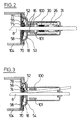
- the sections of FIGS. 2 and 3 show that the pull lever 13 consists of two legs 100 and 101 which are connected by the axes 14 and 15 (FIG. 5).
- the projection 27 on the carriage 26 has a bore 32.
- the tension lever parts 100 and 101 are each provided with a long bore 28.
- a flattened on both sides runs through the bores 28 and the bore 32
- Bolt 103 the component of movement of which is received transversely to the direction of advance of the slide 26 through the long bores 28, and which is rotatable in the bore 32.
- the spring 29 causes the entire feed device to be returned to the illustrated starting position when the trigger 3 is released.
- the carriage guide can be designed as shown in FIG. 6.
- Devices 111 in which inserts 112 are inserted, are present in the housing 21 of the discharge device.
- Corresponding devices 113 of the slide 26 slide in the inserts 112.
- the devices 111 with the inserts 112 and the devices 113 form a tongue and groove sliding system.
- the inserts 112 serve to increase the service life and improve the mechanical properties, such as reduced friction and more precise guidance.
- the clamping levers 30 and 31 are held in the slide 26. As particularly shown in FIG. 5, these each have a bore 43, 44 through which a feed rod 8 passes.
- the bore 43 or 44 is partially towards the front, ie towards the cartridge 4, with a larger cross section.
- the compression spring 34 or 39 is inserted, which is supported and guided by the bore wall in the carriage 26.
- the compression springs 35 and 38 are inserted in a second bore, which press the clamping lever against the opposite pins 41 and 42 with a cambered surface and are also supported on the carriage 26 to the front.
- the bore 43 and 44 may be lined with a material in the area where the feed rod 8 is clamped, for. B. in the form of a socket, which guarantees a long life with good clamping effect.
- release pins 46 and 47 are slidably guided in the feed direction and interact with the release slide 48 resting on the back of the hand-held device.
- the release rod 50 which can be pivoted laterally around the shaft 52 according to FIG. 3, runs under the release slide 48.
- the locking lever 53, 54 In the front part of the housing 21 are in the space between the support plate 18, which is connected to the cartridge holder 104, and the cover plate 58, the locking lever 53, 54. They are set by the springs 74, 75 against the feed rods 8 running through holes in them . Tongues 55, 56 of the locking levers 53, 54 extend into recesses in the shaft 52.
- the feed rods 8 are connected at the rear end by a bridge 17.
- the bridge 17 serves on the one hand from a safety point of view to terminate the feed rods 8 to the rear, prevents a permanent displacement of the feed rods 8 against one another and serves, e.g. when changing the cartridge 4, as a handle for pulling back the feed rods 8.
- the slide 26 is also pulled forward.
- the pins 41 and 42 press eccentrically to the bore 43 and 44 from the rear against the clamping levers 30 and 31. Since in the idle state these always rest against the pins 41 and 42 on the one hand because of the springs 35 and 38, on the other hand the springs 34 and 39 are slightly pretensioned with regard to the clamping of the feed rods 8, a clamp connection between the slide 26 and feed rods 8 is hereby built up without play and evenly by both clamping levers 30 and 31 during the feed.
- the clamping levers 30, 31 move around the Edges 105 and 106, respectively.
- the further forward movement of the slide 26 is then converted into an equal forward movement of the feed rods 8, the tappet plates 7 and finally the squeeze-out piston 110 in the cartridge cylinders 5 and 6, respectively.
- the uniformity of the clamping, and thus ultimately the same advance of the squeezing pistons, is particularly important in multi-component discharge systems for maintaining a constant mixing ratio.
- the construction according to the invention also compensates for different manufacturing play and signs of wear in the clamping elements.
- the trigger 3 is released and the entire feed device automatically returns to the rest position under the action of the spring 29. Since the clamping is released by the clamping levers 30 and 31 during the return movement of the slide 26, the feed rods 8 are not necessarily taken along by this return.
- the clamping levers 30, 31 lie against the wall 108 or 109 of the slide 26 lying in front of them, thereby preventing jamming during the backward movement of the push rods 8.
- the residual friction that still exists between the clamping levers 30, 31 and the feed rods 8 when the carriage 26 runs backward can, in connection with a residual pressure of the cartridge content, lead to a backward entrainment of the feed rods 8.
- a friction brake 65 which is known per se, e.g. B. from the European patent application EP-A-0,408,494 of the applicant, consisting of a slide with a certain friction on one of the feed rods 8 slider 65, the movement of which is limited by a stop 66 relative to the housing 21. Because of a small free path length corresponding to a short retraction of the feed rods 8, running can occur of discharge mass can be prevented.
- the friction brake as shown, only needs to be present on one side, since the stability of the bridge 17 is sufficient to distribute the braking force over both feed rods 8.
- This task is performed by the locking levers 53 and 54, which are shown in another view in FIGS. 2 and 3.
- the locking levers 53 and 54 are pressed backward by the pressure springs 74 and 75, respectively, by rotation about the edge 70.
- any play of the feed rods 8 in the bores of the locking levers 53, 54 is thereby rendered ineffective, and thus both feed rods are locked as precisely as possible at the same time.
- the smallest backward movement of the feed rods 8 then immediately causes the locking levers 53, 54 to jam due to the offset retaining force of the edge 70, which results in a further Backward movement of the feed rods 8 is safely avoided.
- the release rod 50 is pivoted out of the position shown in FIG. 3.
- the slider 48 is moved upwards by sliding the bevel 49 (see FIG. 4) over the release rod 50, as a result of which the pins 46 and 47 (see FIG. 5) are pushed forward over the bevels 107 of the slider 48 and so that the clamping levers 30 and 31 press into the freewheel position. Since the locking levers 53, 54 still absorb the backward pressure, only little force is required for this.
- both of the two backstops specified in the exemplary embodiment may be present or one may be omitted, ie only the friction brake or only the locking lever brake can be present.
- the friction brake could also be used several times, especially for everyone Feed rods are available. It could then consist of several friction bodies or a single larger one, which grips the feed rods.
- the friction brake could also be attached to the housing of the discharge device without play in order to prevent any free return.
- a further position of the release rod could be provided, in which the locking levers 53, 54 are pressed into the freewheel position, but the clamping levers 30, 31 are released, i. H. the slider 48 is not pushed up. In this position, only the friction backstop is effective, as a result of which the discharge device can be quickly switched from the discharge of highly viscous to the discharge of low-viscosity masses.
- locking devices such as Clamping screws that push the locking levers 53, 54 into the freewheel position.
- the exemplary embodiment according to FIG. 7 has some simplifications.
- the handle 2 with the trigger 3 and the double cartridge with the two cylinders 5 and 6 are the same as in the previous example. The same applies to the other components 7-11.
- the pull tab 11 acts via the bearing pin 120 on the pull lever 121, which is rotatably held in the housing via a fixed axis of rotation 122 and is connected to the slide 125 via a bolt 124 sliding in the elongated hole 123.
- a second bore is provided in the housing in order to achieve the gear ratio to be able to change.
- the slide guide is designed similar to that illustrated in FIG. 6.
- the two clamping levers 126 and 127 are arranged in the carriage 125 at the same height, but obliquely with respect to the plane of the push rod, that is, the clamping lever 126 points to the rear in the arrangement of FIG.
- the actuation and action of the clamping levers via pins 41 with a convex surface and the bore 43 with compression spring 34 is the same as in the previous examples, but tension springs 128 fastened to the slide act on the ends of the clamping levers on the push rod side instead of compression springs 35.
- the friction brake 129 is similar in effect and structure to the friction brake 65.
- the exemplary embodiment according to FIG. 7 has above all a more effective unlocking of the backstop containing the locking levers 53 and 54 and the clamping lever.
- This unlocking mechanism which is effective for changing the cartridge or relieving the cartridge against reflowing, contains a first unlocking rocker 130 acting on the clamping levers and a second unlocking rocker 132 acting on the locking levers.
- the first rocker is connected to the second rocker approximately in the middle via a guided rod 133.
- An unlocking lever 134 which is mounted about axis 135 and has a high transmission ratio, engages on the first rocker 130.
- a return spring 136 is connected to the release lever.
- the first rocker 130 has two adjustable threaded bolts 137 which, when the unlocking lever 134 is actuated, act on pressure pins 131 in the slide, and these in turn act on the clamping levers in order to bring them straight, ie into the inactive position.
- the second rocker 132 has a compression spring 138 which is supported on the housing.
- the first rocker 130 acts on the one hand via the threaded bolts 137 on the pressure pins 131 in the slide and these on the outer ends of the clamping levers, and on the other hand directly via the rod 133 on the second rocker 132, which acts on the locking levers, thereby both the Clamping levers as well as the locking levers can be unlocked to enable the push rods to be pulled freely or the cartridges to be relieved.
- the bridge 139 is produced from two shaped pieces which grasp the push rods 8 axially without any play and radially with some play and are screwed together.
- Conventional lightweight materials preferably plastics or light metals, can be used as the material for the housing of the discharge device and for almost all internal parts.
- the more heavily loaded parts such as the lever 13 and its mounting in the housing, the pins 41 and 42 etc. can be made of metal, for example.
- the bearings and also the through bores in the clamping and locking levers 30, 31 or 53, 54 and the slide 26 can be equipped with metal bushings, the feed rods, in order to avoid indentations, to be made of correspondingly hard or surface-hardened material.
- the inside of the guides and the surface of the feed rods can be smoothed or polished to allow the rods to slide easily in the guides. The large clamping forces still ensure sufficient driving force.
Abstract
Description
Die vorliegende Erfindung bezieht sich auf ein Verfahren zum Vorschieben von zwei und mehr Stangen gemäss Oberbegriff des Anspruchs 1 und eine Vorrichtung zur Durchführung des Verfahrens, insbesondere zur Anwendung in einem Handaustraggerät für Zweikomponentenmassen. Ein derartiges Gerät ist beispielsweise aus der DE-A-3 128 611 bekannt. Darin sind die Schubstangen durch je eine Klemmbacke und über einen Bügel von einem Handhebel betätigbar und zur seitlichen Abstützung der Schubstangen ist ein Gegenlager vorgesehen, an dem die Klemmbacken schwenkbar gelagert sind und der Vorschubantrieb enthält einen relativ aufwendigen Schlitten.The present invention relates to a method for advancing two or more bars according to the preamble of claim 1 and a device for carrying out the method, in particular for use in a manual discharge device for two-component materials. Such a device is known for example from DE-A-3 128 611. In it, the push rods can be actuated by a clamping jaw and a bracket by a hand lever, and a counter bearing is provided for lateral support of the push rods, on which the clamping jaws are pivotally mounted and the feed drive contains a relatively complex slide.
Die EP-A-408 494 offenbart ein Handgerät, bei dem ein Verbiegen und Verkanten der Schubstangen wirksam verhindert wird, indem der Vorschubantrieb auf ein Schuborgan wirkt, das im wesentlichen nur in Richtung der Schubstangen auf diese wirkt, die Kraftübertragung jedoch über Zahnstangen erfolgt.EP-A-408 494 discloses a hand-held device in which bending and tilting of the push rods is effectively prevented by the feed drive acting on a push element which acts essentially only in the direction of the push rods, but the force is transmitted via racks.
Ausgehend vom genannten Stand der Technik ist es Aufgabe der vorliegenden Erfindung ein Verfahren anzugeben, bei dem der Vorschubantrieb auch bei hohen Kräften und ohne toten Weg wirksam ist und somit eine einwandfreie Kraftübertragung gewährleistet wird. Insbesondere soll bei der Verwendung für Doppelaustragkartuschen mit unterschiedlichen Durchmessern, bei denen unterschiedliche Reaktionskräfte auf die Schubstangen auftreten, verhindert werden, dass eine relative Verschiebung der Schubstangen gegeneinander erfolgt, damit keine Änderung der volumetrischen Mischungsverhältnisse eintritt. Diese Aufgabe wird mit dem Verfahren wie in den Ansprüchen definiert gelöst. Die weiteren Ansprüche enthalten Vorrichtungen zur Durchführung des Verfahrens.Based on the prior art mentioned, it is an object of the present invention to provide a method in which the feed drive is effective even with high forces and without a dead path, and thus a perfect power transmission is ensured. In particular, when used for double discharge cartridges with different diameters, in which different reaction forces occur on the push rods, the aim is to prevent the push rods from being displaced relative to one another so that the volumetric mixing ratios do not change. This object is achieved with the method as defined in the claims. The other claims contain devices for performing the method.
Demgemäss werden die Vorschubstangen in einem in Richtung des Vorschubs der Auspresskolben bewegbaren Schlitten geführt, der zwei nur lose im Schlitten gehaltene Klemmhebel enthält. Die Klemmhebel weisen eine Durchführung für jeweils eine der Vorschubstangen auf. Bei einer Vorwärtsbewegung des Schlittens, d. h. in Austragrichtung, werden die Klemmhebel versetzt zu dieser Durchführung angetrieben, wodurch sich ein Drehmoment ergibt, das zu einer Verkantung der Klemmhebel an den Vorschubstangen im Bereich der Durchführung führt. Bei einer weiteren Vorwärtsbewegung des Schlittens können die Klemmhebel sich nicht mehr drehen, werden mitgenommen und übertragen damit die Vorwärtsbewegung auf die geklemmten Schubstangen. Da der Weg des Antriebs der Klemmhebel bis zur erreichten Klemmung als Totweg nach aussen hin auftritt, ist durch geeignete Massnahmen, wie Passung der Klemmhebeldurchführungen für die Vorschubstangen, harte Oberflächen usw. dafür zu sorgen, dass dieser Weg klein ist. Unterschiede des Totweges der Klemmhebel werden dadurch unwirksam gemacht, dass die Klemmhebel einer kleinen, permanenten Klemmkraft ausgesetzt werden, z. B. durch Andruckfedern.Accordingly, the feed rods are guided in a slide which can be moved in the direction of the feed of the squeezing pistons and which contains two clamping levers which are held only loosely in the slide. The clamping levers each have a bushing for one of the feed rods. When the carriage moves forward, i. H. in the discharge direction, the clamping levers are driven offset to this feedthrough, resulting in a torque which leads to a tilting of the clamping levers on the feed rods in the area of the feedthrough. When the carriage moves forward, the clamping levers can no longer turn, are carried along and thus transmit the forward movement to the clamped push rods. Since the path of the drive of the clamping levers occurs as a dead travel to the outside as far as the clamping is reached, suitable measures, such as fitting the clamping lever bushings for the feed rods, hard surfaces, etc., must ensure that this path is small. Differences in the dead travel of the clamping levers are rendered ineffective by exposing the clamping levers to a small, permanent clamping force, e.g. B. by pressure springs.
Das bei der Klemmung auftretende Biegemoment auf die Schubstangen wird erfindungsgemäss nahezu vollständig im Schlitten aufgenommen, d. h. durch das Verklemmen allein wird die Führung des Schlittens nicht belastet. Dies wird dadurch erreicht, dass einmal die Schubstangen im Schlitten in eng gepassten und gegebenenfalls geschmierten Führungen laufen, und dass die Biegemomente, die über diese Führungen Drehmomente im Schlitten erzeugen, gegenläufig ausgerichtet sind. Dabei bewirkt die durch das Verbiegen der Vorschubstange erzeugte zusätzliche Reibung nicht eine Erschwerung der Vorwärtsbewegung, sondern einen noch festeren mechanischen Kontakt zwischen Schlitten und Vorschubstange. Von Vorteil ist in diesem Zusammenhang eine möglichst enge Anordnung der Vorschubstangenführungen im Schlitten zu den Klemmhebeln.According to the invention, the bending moment on the push rods which occurs during the clamping is almost completely absorbed in the slide, ie the guide of the slide is not loaded by the clamping alone. This is achieved in that the push rods run in the slide in tightly fitted and possibly lubricated guides, and in that the bending moments which generate torques in the slide via these guides are aligned in opposite directions. The additional friction generated by the bending of the feed rod does not make the forward movement more difficult, but rather an even firmer mechanical one Contact between slide and feed rod. In this context, it is advantageous to arrange the feed rod guides as close as possible in the slide to the clamping levers.
Die Schlittenführung muss damit nur noch die Differenz der auf die Kolben wirkenden Kräfte aufnehmen und auf das Gehäuse übertragen. Bei Kartuschen mit einem Mischungsverhältnis 1:1 verschwindet diese Differenz.The slide guide only has to absorb the difference between the forces acting on the pistons and transfer them to the housing. This difference disappears for cartridges with a mixing ratio of 1: 1.
Als Schlittenführung kann es genügen, nur die Schubstangen im Gehäuse zu führen, beispielsweise beim Ein- und Austritt aus diesem. Oft ist ratsam, für den Schlitten eigene Führungen vorzusehen. Je exakter diese Führung arbeitet, desto weniger kann sich der Schlitten unter den unterschiedlichen Kolbendrücken verkanten, und die Abweichungen im Mischungsverhältnis, die sich daraus ergeben würden, werden minimiert. Auch kann die Schlittenführung an die auftretenden Beanspruchungen besser angepasst werden, wodurch die auftretenden Reibungskräfte gegenüber einer Führung über die Schubstangen vermindert werden.As a slide guide, it can be sufficient to guide only the push rods in the housing, for example when entering and exiting the latter. It is often advisable to provide separate guides for the sled. The more precisely this guide works, the less the slide can jam under the different piston pressures, and the deviations in the mixing ratio that would result from this are minimized. The slide guide can also be better adapted to the stresses that occur, as a result of which the frictional forces that occur are reduced compared to a guide via the push rods.
Für Leichtgängigkeit und lange Haltbarkeit haben die Schubstangen, die Durchtrittsöffnungen der Klemmhebel sowie eventuell auch die Führungen der Schubstangen im Schlitten eine harte und glatte Oberfläche. Die hohen Klemmkräfte bewirken trotzdem eine sichere Mitnahme der Schubstangen. Glatte Oberflächen erlauben ein Zurückziehen der Schubstangen mit geringerem Kraftaufwand trotz der relativ zahlreichen Führungen.For smooth operation and long durability, the push rods, the passage openings of the clamping levers and possibly also the guides of the push rods in the slide have a hard and smooth surface. The high clamping forces nevertheless ensure that the push rods are carried safely. Smooth surfaces allow the push rods to be pulled back with less effort despite the relatively large number of guides.
Mit der erfindungsgemässen Vortriebsvorrichtung lassen sich weitere, zum Teil bekannte und in der Praxis vorteilhafte Vorrichtungen leicht kombinieren. Beispiele dafür sind Rücklaufsperre(n), Entriegelung der Rücklaufsperre(n) und Blockierung der Klemmhebel, um das Zurückziehen der Schubstangen zu ermöglichen.With the propulsion device according to the invention, further devices, some of which are known and advantageous in practice, can be easily combined. Examples of this are the backstop (s), unlocking the backstop (s) and Locking of the clamping levers to allow the push rods to be pulled back.
Die Erfindung soll anhand eines Ausführungsbeispiels weiter erklärt werden.
- Figur 1
- zeigt einen Schnitt durch ein Ausführungsbeispiel der Erfindung,
Figur 2- zeigt einen Schnitt des Gerätes von Figur 1 gemäss der Linie II - II,
- Figur 3
- zeigt einen Schnitt des Gerätes von Figur 1 gemäss der Linie III - III,
- Figur 4
- zeigt eine Aufsicht auf den
Schieber 48, Figur 5- zeigt eine Auschnittsvergrösserung des Gerätes von Figur 1,
Figur 6- zeigt einen vereinfachten Schnitt gemäss der Linie V - V in Figur 1, und
Figur 7- zeigt einen Schnitt eines weiteren Ausführungsbeispiels der Erfindung.
- Figure 1
- shows a section through an embodiment of the invention,
- Figure 2
- shows a section of the device of Figure 1 along the line II - II,
- Figure 3
- shows a section of the device of Figure 1 along the line III - III,
- Figure 4
- shows a plan view of the
slide 48, - Figure 5
- shows an enlarged detail of the device of Figure 1,
- Figure 6
- shows a simplified section along the line V - V in Figure 1, and
- Figure 7
- shows a section of a further embodiment of the invention.
Figur 1 stellt ein erstes Ausführungsbeispiel eines erfindungsgemässen Handgerätes dar mit einem Gehäuse 21, einem Griff 2, einem Abzughebel 3, sowie die Doppelkartusche 4 mit den beiden Zylindern 5 und 6, die nur teilweise, da bekannt, gezeichnet sind. Die beiden Komponenten der Doppelkartusche werden während des Austragsvorgangs in einem vorgeschalteten statischen Mischer gemischt, worauf sie chemisch reagieren und aushärten bzw. sich verfestigen. Dabei sollte das Austragen der beiden Komponenten aus den Zylindern durch gleichzeitiges Betätigen von in jedem Zylinder angeordneten Auspresskolben erfolgen, wodurch die Massen durch die stirnseitige Austrittsöffnung (nicht gezeichnet) des Statikmischers ausgepresst werden. Die Doppelkartusche 4 ist nicht eigentlicher Gegenstand der vorliegenden Erfindung und ist beispielsweise in der EP-A-294 672 des gleichen Anmelders eingehend beschrieben worden. Das erfindungsgemässe Handgerät ist jedoch nicht auf die Betätigung solcher Doppelkartuschen beschränkt, eignet sich jedoch besonders dafür.Figure 1 shows a first embodiment of a hand-held device according to the invention with a
Da die auszutragenden Massen recht zähflüssig sein können, müssen relativ hohe Kräfte aufgewendet werden, um diese auszutragen. Andererseits ist eine möglichst genaue Dosierung unter genauer Einhaltung des Mischverhältnisses der auszutragenden Massen wünschenswert, so dass insgesamt hohe Anforderungen an die mechanischen Komponenten eines solchen Gerätes gestellt werden, denn einerseits muss der Vortrieb leichtgängig sein und auch bei grossen Kräften nicht klemmen und andererseits genau sein, damit keine relative Verschiebung der Schubstangen eintreten kann. Die in den Kartuschen befindlichen Auspresskolben 110 werden durch die Stösselplatten 7 an den Enden der Schubstangen 8 betätigt. Diese Schubstangen werden über einen Hebelmechanismus vom Abzughebel 3 angetrieben.Since the masses to be discharged can be quite viscous, relatively high forces have to be used to discharge them. On the other hand, it is desirable to dose as precisely as possible while precisely observing the mixing ratio of the masses to be discharged, so that overall high demands are placed on the mechanical components of such a device, because on the one hand the propulsion must be smooth and not jammed even with large forces and on the other hand it must be precise, so that no relative displacement of the push rods can occur. The
Der an einer Drehachse 9 befestigte Abzughebel 3 ist über den Lagerzapfen 10 mit einer ersten Zuglasche 11 eines Zughebels 13 verbunden, der mit der Zuglasche 11 über einen Lagerzapfen 14 verbunden ist und über eine ortsfeste Drehachse 15 im Lagerbock 16 drehbar gehalten ist. Die Schnitte der Fig. 2 und 3 zeigen, dass der Zughebel 13 aus zwei Schenkeln 100 und 101 besteht, die durch die Achsen 14 und 15 (Fig. 5) verbunden sind. Der Vorsprung 27 am Schlitten 26 weist eine Bohrung 32 auf. Die Zughebelteile 100 und 101 sind jeweils mit einer Langbohrung 28 versehen. Durch die Bohrungen 28 und die Bohrung 32 verläuft ein beidseitig abgeflachter Bolzen 103, dessen Bewegungskomponente quer zur Vorschubrichtung des Schlittens 26 durch die Langbohrungen 28 aufgenommen wird, und der in der Bohrung 32 drehbar ist. Die Feder 29 bewirkt das Zurückstellen der gesamten Vorschubvorrichtung in die dargestellte Ausgangsstellung, wenn der Abzughebel 3 losgelassen wird.The trigger lever 3 fastened to an axis of
Die Schlittenführung kann wie in Fig. 6 gezeigt ausgeführt sein. Im Gehäuse 21 des Austraggeräts sind Vorrichtungen 111 vorhanden, in die Einsätze 112 eingelegt sind. In den Einsätzen 112 gleiten entsprechende Vorrichtungen 113 des Schlittens 26. Im vorliegenden Beispiel bilden die Vorrichtungen 111 mit den Einsätzen 112 und die Vorrichtungen 113 ein Nut-Feder-Gleitsystem. Die Einsätze 112 dienen dabei der Erhöhung der Lebensdauer und der Verbesserung der mechanischen Eigenschaften, wie verminderte Reibung und exaktere Führung.The carriage guide can be designed as shown in FIG. 6.
Im Schlitten 26 sind die Klemmhebel 30 und 31 gehalten. Diese weisen, wie besonders Fig. 5 zeigt, jeweils eine Bohrung 43, 44 auf, durch die jeweils eine Vorschubstange 8 hindurchtritt. Die Bohrung 43 bzw. 44 ist nach vorne zu, d. h. zur Kartusche 4 hin, teilweise mit einem grösseren Querschnitt ausgeführt. In dem dadurch entstehenden Spalt zwischen Vorschubstange 8 und Bohrungswand ist die Druckfeder 34 bzw. 39 eingesetzt, die durch die Bohrungswand im Schlitten 26 abgestützt und geführt wird. Nahe dem anderen Ende der Klemmhebel 30 und 31 sind in einer zweiten Bohrung die Druckfedern 35 bzw. 38 eingesetzt, die den Klemmhebel gegen die gegenüberliegenden Zapfen 41 bzw. 42 mit bombierter Oberfläche andrücken und sich ebenfalls am Schlitten 26 nach vorne abstützen. Die Bohrung 43 bzw. 44 kann in dem Bereich, wo die Klemmung der Vorschubstange 8 erfolgt, mit einem Material ausgekleidet sein, z. B. in Form einer Buchse, das eine lange Lebensdauer bei guter Klemmwirkung garantiert.The clamping levers 30 and 31 are held in the
Im Schlitten 26 sind in Vorschubrichtung verschiebbar die Lösestifte 46 und 47 geführt, die mit dem auf der Rückseite des Handgeräts aufliegenden Löseschieber 48 zusammenwirken. Unter dem Löseschieber 48 verläuft die Freigabestange 50, die gemäss Fig. 3 seitlich um die Welle 52 verschwenkt werden kann.In the
Im Vorderteil des Gehäuses 21 befinden sich im Raum zwischen der Tragplatte 18, die mit dem Kartuschenhalter 104 verbunden ist, und der Abdeckplatte 58 die Sperrhebel 53, 54. Sie werden von den Federn 74, 75 gegen die durch Bohrungen in ihnen verlaufenden Vorschubstangen 8 angestellt. In Ausnehmungen der Welle 52 reichen Zungen 55, 56 der Sperrhebel 53, 54.In the front part of the
Die Vorschubstangen 8 sind am hinteren Ende durch eine Brücke 17 verbunden. Die Brücke 17 dient einerseits aus sicherheitstechnischen Gesichtspunkten als Abschluss der Vorschubstangen 8 nach hinten, verhindert eine permanente Verschiebung der Vorschubstangen 8 gegeneinander und dient, z.B. beim Wechseln der Kartusche 4, als Griff zum Zurückziehen der Vorschubstangen 8.The
Wird der Abzughebel 3 in Richtung des Griffs 2 bewegt, so wird die Lasche 11 und über den Hebel 13 auch der Schlitten 26 nach vorne gezogen. Dabei drücken zunächst die Zapfen 41 bzw. 42 exzentrisch zur Bohrung 43 bzw. 44 von hinten gegen die Klemmhebel 30 bzw. 31. Da diese im Ruhezustand einerseits wegen der Federn 35 bzw. 38 immer an den Zapfen 41 bzw. 42 anliegen, andererseits von den Federn 34 bzw. 39 hinsichtlich der Klemmung der Vorschubstangen 8 leicht vorgespannt werden, wird hierdurch spielfrei und gleichmässig von beiden Klemmhebeln 30 und 31 während des Vorschubs eine Klemmverbindung zwischen Schlitten 26 und Vorschubstangen 8 aufgebaut. Die Klemmhebel 30, 31 bewegen sich dabei um die Kanten 105 bzw. 106. Die weitere Vorwärtsbewegung des Schlittens 26 wird dann in eine gleiche Vorwärtsbewegung der Vorschubstangen 8, der Stösselplatten 7 und schliesslich der Auspresskolben 110 in den Kartuschenzylindern 5 bzw. 6 umgesetzt. Die Gleichmässigkeit der Klemmung, und damit gleichbedeutend letztendlich der gleiche Vorschub der Auspresskolben ist bei Mehrkomponentenaustragsystemen besonders wichtig für die Einhaltung eines konstanten Mischungsverhältnisses. Durch die erfindungsgemässe Konstruktion werden auch unterschiedliche Fertigungsspiele sowie Abnützungserscheinungen in den Klemmelementen ausgeglichen.If the trigger 3 is moved in the direction of the
Ist genügend Masse aus der Kartusche 4 herausgedrückt worden, so wird der Abzughebel 3 losgelassen und die gesamte Vorschubeinrichtung geht unter der Wirkung der Feder 29 selbsttätig in die Ruhestellung zurück. Da die Klemmung durch die Klemmhebel 30 bzw. 31 bei der Rückbewegung des Schlittens 26 aufgehoben wird, werden die Vorschubstangen 8 durch diesen Rücklauf nicht zwangsweise mitgenommen. Die Klemmhebel 30, 31 legen sich dabei an die vor ihnen liegende Wand 108 bzw. 109 des Schlittens 26 an, wodurch ein Verklemmen bei der Rückwärtsbewegung der Schubstangen 8 verhindert wird.If sufficient mass has been pressed out of the cartridge 4, the trigger 3 is released and the entire feed device automatically returns to the rest position under the action of the
Die beim Zurücklaufen des Schlittens 26 noch vorhandene Restreibung zwischen den Klemmhebeln 30, 31 und den Vorschubstangen 8 kann im Zusammenhang mit einem Restdruck des Kartuscheninhalts zu einer Rückwärtsmitnahme der Vorschubstangen 8 führen. Dies wird verhindert durch eine Reibungsbremse 65, die an sich bekannt ist, z. B. aus der europäischen Patentanmeldung EP-A-0,408,494 des Anmelders, bestehend aus einem mit einer gewissen Reibung auf einer der Vorschubstangen 8 verschiebbaren Schieber 65, dessen Bewegung gegenüber dem Gehäuse 21 durch einen Anschlag 66 begrenzt wird. Durch eine kleine freie Weglänge entsprechend einem kurzen Rückzug der Vorschubstangen 8 kann ein Nachlaufen von Austragmasse verhindert werden. Die Reibungsbremse braucht, wie dargestellt, nur einseitig vorhanden zu sein, da die Stabilität der Brücke 17 ausreicht, um die Bremskraft auf beide Vorschubstangen 8 zu verteilen.The residual friction that still exists between the clamping levers 30, 31 and the
Bei dickflüssigeren Austragmassen, die unter relativ hohem Druck ausgepresst werden, genügt eine solche einfache Rücklaufbremse nicht mehr, da sich unter dem nötigen hohen Austragdruck der Kartuschenkörper nicht mehr vernachlässigbar elastisch verformt. Beim Beginn des Auspressens muss zunächst die damit einhergehende Volumenvergrösserung bewältigt werden, bevor ein Austragen im wesentlichen entsprechend dem Presskolbenvorschub erfolgt. Dieser anfängliche Totweg würde immer wieder auftreten, wenn die Vorschubstangen 8 beim Loslassen des Abzughebels 3 beliebig zurücklaufen könnten. Soll das Austraggerät auch für höherviskose Austragmedien verwendbar sein, ist eine Vorrichtung, die eine Rückwärtsbewegung der Vorschubstangen 8 verhindert, daher sehr wünschenswert.In the case of more viscous discharge masses which are pressed out under relatively high pressure, such a simple reverse brake is no longer sufficient, since the cartridge body is no longer negligibly elastically deformed under the necessary high discharge pressure. At the beginning of the squeezing, the associated increase in volume must first be managed before it is discharged essentially in accordance with the plunger feed. This initial dead travel would occur again and again if the
Diese Aufgabe übernehmen die Sperrhebel 53 und 54, die in den Fig. 2 und 3 nochmals in einer anderen Ansicht dargestellt sind. Während des Vorschubs liegen sie an der Platte 58 auf, so dass die Vorschubstangen 8 ungebremst durch die entsprechenden Bohrungen in den Sperrhebeln 53, 54 durchgleiten können. Hört dagegen die Vorwärtsbewegung auf, werden die Sperrhebel 53 und 54 von den Andruckfedern 74 bzw. 75 unter Drehung um die Kante 70 nach hinten gedrückt. Dadurch wird analog zu den Klemmhebeln 30, 31 ein etwaiges Spiel der Vorschubstangen 8 in den Bohrungen der Sperrhebel 53, 54 unwirksam gemacht und somit werden beide Vorschubstangen möglichst genau gleichzeitig gesperrt. Die kleinste Rückwärtsbewegung der Vorschubstangen 8 führt dann sofort zum Verklemmen der Sperrhebel 53, 54 durch die versetzt einwirkende Rückhaltekraft der Kante 70, wodurch eine weitere Rückwärtsbewegung der Vorschubstangen 8 sicher vermieden wird.This task is performed by the locking levers 53 and 54, which are shown in another view in FIGS. 2 and 3. During the feed they rest on the
Zum Wechseln der Kartusche ist es nötig, eine Möglichkeit zum Zurückziehen der Vorschubstangen 8 zu schaffen. Diese muss nicht nur die Sperrhebel 53, 54, sondern auch die Klemmhebel 30 und 31 in eine Freilaufstellung bringen. Hierzu wird die Freigabestange 50 aus der in Fig. 3 dargestellten Stellung herausgeschwenkt. Dabei wird zunächst der Schieber 48 durch das Gleiten der Schräge 49 (siehe Fig. 4) über die Freigabestange 50 nach oben bewegt, wodurch die Stifte 46 und 47 (siehe Fig. 5) über die Schrägen 107 des Schiebers 48 nach vorn geschoben werden und damit die Klemmhebel 30 und 31 in die Freilaufstellung drücken. Da jetzt die Sperrhebel 53, 54 noch den Rückwärtsdruck auffangen, ist hierfür nur wenig Kraft erforderlich. Erst wenn die Freigabestange 50 weiter geschwenkt wird, werden auch die Zungen 55, 56 der Sperrhebel 53 bzw. 54 von der Kante 77 bzw. 78 der mit der Freigabestange 50 gedrehten Welle 52 erfasst und nach vorne gegen die Platte 74 in die Freilaufstellung gedrückt, wonach die Vorschubstangen 8 mit den Stösselplatten 7 durch Zug an der Brücke 17 zurückgezogen werden können.To change the cartridge, it is necessary to create a possibility for retracting the
Der Gefahr, dass sich die Klemmhebel 30, 31 bei einem schnellen manuellen Vorschieben der Vorschubstangen 8 ebenfalls verklemmen, ist dadurch begegnet, dass die Klemmhebel 30, 31 an der vor ihnen liegenden Wand des Schlittens 26 anschlagen, bevor eine in Vorwärtsrichtung wirkende Klemmung auftritt.The risk that the clamping levers 30, 31 also jam when the
Von den beiden im Ausführungsbeispiel angegebenen Rücklaufsperren können je nach Anwendung beide vorhanden sein oder eine weggelassen werden, d. h. es kann nur die Reibungsbremse oder nur die Sperrhebelbremse vorhanden sein. Die Reibungsbremse könnte auch mehrfach, insbesondere für alle Vorschubstangen vorhanden sein. Sie könnte dann aus mehreren Reibungskörpern bestehen oder aus einem einzigen grösseren, der die Vorschubstangen erfasst. Die Reibungsbremse könnte auch gegenüber dem Gehäuse des Austraggeräts spielfrei angebracht sein, um jeglichen freien Rücklauf zu verhindern. Es kann statt den beiden beschriebenen Sperrhebeln auch nur ein Sperrhebel vorhanden sein, wobei dann die Sperrwirkung auf die andere(n), nicht vom Sperrhebel erfasste(n) Vorschubstange(n) von der Brücke 17 übertragen wird.Depending on the application, both of the two backstops specified in the exemplary embodiment may be present or one may be omitted, ie only the friction brake or only the locking lever brake can be present. The friction brake could also be used several times, especially for everyone Feed rods are available. It could then consist of several friction bodies or a single larger one, which grips the feed rods. The friction brake could also be attached to the housing of the discharge device without play in order to prevent any free return. Instead of the two locking levers described, there can also be only one locking lever, in which case the locking action is transferred from the
Es könnte eine weitere Stellung der Freigabestange vorgesehen sein, in der zwar die Sperrhebel 53, 54 in die Freilaufstellung gedrückt werden, jedoch die Klemmhebel 30, 31 freigegeben sind, d. h. der Schieber 48 nicht hochgedrückt ist. In dieser Stellung ist damit nur die Reibungsrücklaufsperre wirksam, wodurch das Austraggerät schnell von dem Austragen von hochviskosen auf das Austragen von niedrigerviskosen Massen umgestellt werden kann.A further position of the release rod could be provided, in which the locking levers 53, 54 are pressed into the freewheel position, but the clamping levers 30, 31 are released, i. H. the
Eine Alternative wären Feststellmittel wie z.B. Klemmschrauben, die die Sperrhebel 53, 54 in die Freilaufstellung drücken.An alternative would be locking devices such as Clamping screws that push the locking levers 53, 54 into the freewheel position.
Das Ausführungsbeispiel gemäss Figur 7 weist einige Vereinfachungen auf. Der Griff 2 mit dem Abzughebel 3 sowie die Doppelkartusche mit den beiden Zylindern 5 und 6 sind dieselben wie im vorhergehenden Beispiel. Dasselbe gilt für die übrigen Komponenten 7-11. Aehnlich wie bei den vorhergehenden Beispielen wirkt die Zuglasche 11 über den Lagerzapfen 120 auf den Zughebel 121, der über eine ortsfeste Drehachse 122 im Gehäuse drehbar gehalten und über einen im Langloch 123 gleitenden Bolzen 124 mit dem Schlitten 125 verbunden ist. Im Gehäuse ist ausser der Bohrung für die Achse 122 eine zweite Bohrung vorgesehen, um das Uebersetzungsverhältnis ändern zu können. Die Schlittenführung ist ähnlich wie in Figur 6 veranschaulicht ausgeführt.The exemplary embodiment according to FIG. 7 has some simplifications. The
In Abweichung zu den vorhergehenden Ausführungen sind die beiden Klemmhebel 126 und 127 im Schlitten 125 auf gleicher Höhe, jedoch bezüglich der Schubstangenebene schräg gegeneinander angeordnet, das heisst, Klemmhebel 126 weist in der Anordnung von Figur 7 nach hinten. Die Betätigung und Wirkung der Klemmhebel über Zapfen 41 mit bombierter Oberfläche und die Bohrung 43 mit Druckfeder 34 ist dieselbe wie bei den vorhergehenden Beispielen, wobei jedoch am Schlitten befestigte Zugfedern 128 anstatt Druckfedern 35 auf die schubstangenseitigen Enden der Klemmhebel wirken. Die Reibungsbremse 129 ist ähnlich der Reibungsbremse 65 in ihrer Wirkung und im Aufbau.In a departure from the previous embodiments, the two clamping
Das Ausführungsbeispiel gemäss Figur 7 weist vor allem eine wirksamere Entriegelung der die Sperrhebel 53 und 54 enthaltenden Rücklaufsperre und der Klemmhebel auf. Dieser für den Kartuschenwechsel oder die Kartuschenentlastung gegen Nachfliessen wirksame Entriegelungsmechanismus enthält eine erste auf die Klemmhebel wirkende Entriegelungswippe 130 und eine auf die Sperrhebel wirkende zweite Entriegelungswippe 132. Die erste Wippe ist etwa in der Mitte über eine geführte Stange 133 mit der zweiten Wippe verbunden. An der ersten Wippe 130 greift ein Entriegelungshebel 134 an, der um Achse 135 gelagert ist und eine hohe Uebersetzung aufweist. Eine Rückholfeder 136 ist mit dem Entriegelungshebel verbunden. Die erste Wippe 130 weist zwecks Toleranzausgleich zwei einstellbare Gewindebolzen 137 auf, die bei Betätigung des Entriegelungshebels 134 auf Druckstifte 131 im Schlitten wirken, und diese wiederum auf die Klemmhebel, um diese gerade, d.h. in die unwirksame Stellung zu bringen. Um die Wippen unter Vorspannung zu halten, weist die zweite Wippe 132 eine Druckfeder 138 auf, die sich am Gehäuse abstützt.The exemplary embodiment according to FIG. 7 has above all a more effective unlocking of the backstop containing the locking levers 53 and 54 and the clamping lever. This unlocking mechanism, which is effective for changing the cartridge or relieving the cartridge against reflowing, contains a first unlocking
Beim Betätigen des Entriegelungshebels wirkt die erste Wippe 130 einerseits über die Gewindebolzen 137 auf die Druckstifte 131 im Schlitten und diese auf die äusseren Enden der Klemmhebel und andererseits über die Stange 133 direkt auf die zweite Wippe 132, die auf die Sperrhebel wirkt, wodurch sowohl die Klemmhebel als auch die Sperrhebel entriegelt werden, um das freie Ziehen der Schubstangen oder die Entlastung der Kartuschen zu ermöglichen.When the unlocking lever is actuated, the
Falls die Schubstangen nicht die gleichen Durchmesser aufweisen, ist die stärkere Schubstange fest geführt, während die andere Schubstange mit leichtem Spiel geführt ist. In einer Ausführungsvariante ist die Brücke 139 aus zwei Formstücken hergestellt, die die Schubstangen 8 axial ohne jedes Spiel und radial mit etwas Spiel fassen und miteinander verschraubt sind.If the push rods do not have the same diameter, the stronger push rod is firmly guided, while the other push rod is guided with slight play. In one embodiment variant, the
Als Material für das Gehäuse des Austraggeräts sowie fast aller Innenteile können übliche Leichtbaumaterialien verwendet werden, bevorzugt Kunststoffe oder Leichtmetalle. Die höher belasteten Teile, wie der Hebel 13 und seine Lagerung im Gehäuse, die Zapfen 41 und 42 usw. können beispielsweise aus Metall hergestellt werden. Die Lager und ebenso die Durchtrittsbohrungen in den Klemm- und Sperrhebeln 30, 31 bzw. 53, 54 und dem Schlitten 26 können mit Metallbuchsen ausgestattet sein, wobei die Vorschubstangen, um Eindruckstellen zu vermeiden, aus entsprechend hartem bzw. oberflächengehärtetem Material gefertigt werden können. Das Innere der Führungen und die Oberfläche der Vorschubstangen kann geglättet oder poliert sein, um ein leichtes Gleiten der Stangen in den Führungen zu ermöglichen. Die grossen Klemmkräfte stellen trotzdem eine ausreichende Mitnahmekraft sicher.Conventional lightweight materials, preferably plastics or light metals, can be used as the material for the housing of the discharge device and for almost all internal parts. The more heavily loaded parts, such as the
Claims (16)
Applications Claiming Priority (2)
| Application Number | Priority Date | Filing Date | Title |
|---|---|---|---|
| CH758/92 | 1992-03-10 | ||
| CH275892 | 1992-09-02 |
Publications (2)
| Publication Number | Publication Date |
|---|---|
| EP0586342A1 true EP0586342A1 (en) | 1994-03-09 |
| EP0586342B1 EP0586342B1 (en) | 1996-12-27 |
Family
ID=4240956
Family Applications (1)
| Application Number | Title | Priority Date | Filing Date |
|---|---|---|---|
| EP93810592A Expired - Lifetime EP0586342B1 (en) | 1992-09-02 | 1993-08-23 | Method for driving several rods, particularly for manual dispensing devices |
Country Status (4)
| Country | Link |
|---|---|
| US (1) | US5392956A (en) |
| EP (1) | EP0586342B1 (en) |
| JP (1) | JP3591852B2 (en) |
| DE (1) | DE59304874D1 (en) |
Cited By (2)
| Publication number | Priority date | Publication date | Assignee | Title |
|---|---|---|---|---|
| US5477987A (en) * | 1993-01-15 | 1995-12-26 | Keller; Wilhelm A. | Dispensing appliance for at least two components |
| US5546996A (en) * | 1994-08-09 | 1996-08-20 | Minnesota Mining And Manufacturing Company | Dispensing cartridge refillng system |
Families Citing this family (7)
| Publication number | Priority date | Publication date | Assignee | Title |
|---|---|---|---|---|
| MY129800A (en) * | 1996-01-19 | 2007-04-30 | Johnson S C Comm Markets Inc | Dual piston variable proportioning system |
| CN2598664Y (en) * | 2003-03-11 | 2004-01-14 | 李�杰 | Feeding device of gum-spray gun |
| US6938799B1 (en) * | 2003-08-11 | 2005-09-06 | Kenneth R. Berntsen | Sealant/adhesive gun |
| US20050103809A1 (en) * | 2003-11-13 | 2005-05-19 | Mixpac Systems Ag | Electrically operated cartridge dispensing appliance |
| CA2741062C (en) * | 2011-05-20 | 2013-11-26 | Jdi Design Inc. | Ergonomic portion measuring fluent material dispensing system |
| DE102012201295A1 (en) * | 2012-01-31 | 2013-08-01 | Hilti Aktiengesellschaft | dispenser to |
| EP3251755A1 (en) | 2016-05-31 | 2017-12-06 | Sulzer Mixpac AG | Two-component dispenser |
Citations (1)
| Publication number | Priority date | Publication date | Assignee | Title |
|---|---|---|---|---|
| DE3128611A1 (en) * | 1981-07-20 | 1983-01-27 | Hilti AG, 9494 Schaan | DOSING UNIT FOR MULTI-COMPONENT MEASURES |
Family Cites Families (10)
| Publication number | Priority date | Publication date | Assignee | Title |
|---|---|---|---|---|
| GB1011470A (en) * | 1963-11-06 | 1965-12-01 | Expandite Ltd | Improvements relating to guns for applying viscous materials such as mastics |
| US3311265A (en) * | 1965-06-03 | 1967-03-28 | Chem Dev Corp | Double-barreled dispensing gun |
| DE3234250A1 (en) * | 1982-09-15 | 1984-03-15 | Hilti AG, 9494 Schaan | HAND DEVICE FOR DELIVERING MULTI-COMPONENT DIMENSIONS |
| US4655372A (en) * | 1984-09-21 | 1987-04-07 | The Joy Of Painting | Paint dispenser |
| EP0294672B1 (en) * | 1987-06-10 | 1992-08-12 | Wilhelm A. Keller | Double cartridge for a two-component compound |
| DE59004543D1 (en) * | 1989-07-13 | 1994-03-24 | Wilhelm A Keller | Manual discharge device for a double discharge cartridge for two-component materials. |
| DE59102231D1 (en) * | 1990-06-22 | 1994-08-25 | Wilhelm A Keller | Electrically operated discharge device. |
| US5137181A (en) * | 1990-07-18 | 1992-08-11 | Wilhelm A. Keller | Manually operated appliance, in particular for a double dispensing cartridge for two-component substances |
| US5197635A (en) * | 1990-11-16 | 1993-03-30 | Chang Peter J Y | Variable thrust caulk dispensing device |
| US5263614A (en) * | 1992-05-14 | 1993-11-23 | Jacobsen Kenneth H | Material dispensing tool for tubular cartridges |
-
1993
- 1993-08-23 DE DE59304874T patent/DE59304874D1/en not_active Expired - Lifetime
- 1993-08-23 EP EP93810592A patent/EP0586342B1/en not_active Expired - Lifetime
- 1993-09-02 JP JP21887993A patent/JP3591852B2/en not_active Expired - Lifetime
- 1993-09-02 US US08/114,903 patent/US5392956A/en not_active Expired - Lifetime
Patent Citations (1)
| Publication number | Priority date | Publication date | Assignee | Title |
|---|---|---|---|---|
| DE3128611A1 (en) * | 1981-07-20 | 1983-01-27 | Hilti AG, 9494 Schaan | DOSING UNIT FOR MULTI-COMPONENT MEASURES |
Cited By (2)
| Publication number | Priority date | Publication date | Assignee | Title |
|---|---|---|---|---|
| US5477987A (en) * | 1993-01-15 | 1995-12-26 | Keller; Wilhelm A. | Dispensing appliance for at least two components |
| US5546996A (en) * | 1994-08-09 | 1996-08-20 | Minnesota Mining And Manufacturing Company | Dispensing cartridge refillng system |
Also Published As
| Publication number | Publication date |
|---|---|
| DE59304874D1 (en) | 1997-02-06 |
| EP0586342B1 (en) | 1996-12-27 |
| JPH07797A (en) | 1995-01-06 |
| JP3591852B2 (en) | 2004-11-24 |
| US5392956A (en) | 1995-02-28 |
Similar Documents
| Publication | Publication Date | Title |
|---|---|---|
| DE3128611C2 (en) | Dosing device for multi-component masses | |
| EP0589828B1 (en) | Feed for an extrusion tool | |
| DE3234250C2 (en) | ||
| DE2546696C3 (en) | Medical stapling instrument for closing tubular organic structures such as blood vessels | |
| EP0615787B1 (en) | Manual dispensing device for double cartridge | |
| EP0507147A1 (en) | Coupling | |
| EP0956908A1 (en) | Electrically driven dispensing apparatus for cartridges | |
| EP0463990A1 (en) | Electrically driven dispensing apparatus | |
| EP0791404A1 (en) | Manual discharge device for a double cartridge | |
| EP0586342B1 (en) | Method for driving several rods, particularly for manual dispensing devices | |
| DE10020591B4 (en) | Dispensing device for viscous dental material | |
| DE1515360B2 (en) | Pressing tool for pressing electrical connection terminals | |
| EP0408494B1 (en) | Manually operated discharging device for a double cartridge for a two-component compound | |
| DE1627730A1 (en) | Device for the assembly of nuts and washers or the like. with screw bolts or the like. | |
| EP1101538A2 (en) | Electrically driven dispensing apparatus for cartridges | |
| EP0621083A1 (en) | Device for emptying cartridges | |
| DE3610060A1 (en) | Clamping device | |
| WO2004110532A1 (en) | Drive device and method for advancing an advancing element | |
| EP0736333A2 (en) | Hand actuated extrusion device for pasty material | |
| EP0173169A1 (en) | Swing clamp | |
| EP0274746B1 (en) | Clamp with adjustable jaws | |
| DE2659768A1 (en) | CLAMPING DEVICE FOR FRICTION BRAKES, IN PARTICULAR OF RAIL VEHICLES | |
| DE3941752A1 (en) | TORQUE DEVICE | |
| DE3306524A1 (en) | DOSING DEVICE | |
| DE3112809C2 (en) |
Legal Events
| Date | Code | Title | Description |
|---|---|---|---|
| PUAI | Public reference made under article 153(3) epc to a published international application that has entered the european phase |
Free format text: ORIGINAL CODE: 0009012 |
|
| AK | Designated contracting states |
Kind code of ref document: A1 Designated state(s): CH DE FR GB IT LI |
|
| 17P | Request for examination filed |
Effective date: 19940822 |
|
| GRAG | Despatch of communication of intention to grant |
Free format text: ORIGINAL CODE: EPIDOS AGRA |
|
| GRAH | Despatch of communication of intention to grant a patent |
Free format text: ORIGINAL CODE: EPIDOS IGRA |
|
| 17Q | First examination report despatched |
Effective date: 19960529 |
|
| GRAH | Despatch of communication of intention to grant a patent |
Free format text: ORIGINAL CODE: EPIDOS IGRA |
|
| GRAA | (expected) grant |
Free format text: ORIGINAL CODE: 0009210 |
|
| ITF | It: translation for a ep patent filed |
Owner name: BARZANO' E ZANARDO MILANO S.P.A. |
|
| AK | Designated contracting states |
Kind code of ref document: B1 Designated state(s): CH DE FR GB IT LI |
|
| REG | Reference to a national code |
Ref country code: CH Ref legal event code: NV Representative=s name: AMMANN PATENTANWAELTE AG BERN |
|
| REF | Corresponds to: |
Ref document number: 59304874 Country of ref document: DE Date of ref document: 19970206 |
|
| GBT | Gb: translation of ep patent filed (gb section 77(6)(a)/1977) |
Effective date: 19970303 |
|
| ET | Fr: translation filed | ||
| PLBE | No opposition filed within time limit |
Free format text: ORIGINAL CODE: 0009261 |
|
| STAA | Information on the status of an ep patent application or granted ep patent |
Free format text: STATUS: NO OPPOSITION FILED WITHIN TIME LIMIT |
|
| 26N | No opposition filed | ||
| REG | Reference to a national code |
Ref country code: GB Ref legal event code: IF02 |
|
| REG | Reference to a national code |
Ref country code: GB Ref legal event code: 732E |
|
| REG | Reference to a national code |
Ref country code: FR Ref legal event code: TP |
|
| REG | Reference to a national code |
Ref country code: CH Ref legal event code: PUE Owner name: MIXPAC SYSTEMS AG Free format text: KELLER, WILHELM A.#OBSTGARTENWEG 9#CH-6402 MERLISCHACHEN (CH) -TRANSFER TO- MIXPAC SYSTEMS AG#GRUNDSTRASSE 12#6343 ROTKREUZ (CH) |
|
| PGFP | Annual fee paid to national office [announced via postgrant information from national office to epo] |
Ref country code: CH Payment date: 20110824 Year of fee payment: 19 |
|
| PGFP | Annual fee paid to national office [announced via postgrant information from national office to epo] |
Ref country code: GB Payment date: 20120821 Year of fee payment: 20 |
|
| PGFP | Annual fee paid to national office [announced via postgrant information from national office to epo] |
Ref country code: FR Payment date: 20120906 Year of fee payment: 20 Ref country code: IT Payment date: 20120822 Year of fee payment: 20 Ref country code: DE Payment date: 20120822 Year of fee payment: 20 |
|
| REG | Reference to a national code |
Ref country code: DE Ref legal event code: R071 Ref document number: 59304874 Country of ref document: DE |
|
| REG | Reference to a national code |
Ref country code: CH Ref legal event code: PL |
|
| REG | Reference to a national code |
Ref country code: GB Ref legal event code: PE20 Expiry date: 20130822 |
|
| PG25 | Lapsed in a contracting state [announced via postgrant information from national office to epo] |
Ref country code: DE Free format text: LAPSE BECAUSE OF EXPIRATION OF PROTECTION Effective date: 20130824 |
|
| PG25 | Lapsed in a contracting state [announced via postgrant information from national office to epo] |
Ref country code: GB Free format text: LAPSE BECAUSE OF EXPIRATION OF PROTECTION Effective date: 20130822 |