EP0586999A2 - Neural network based controller for a machine in particular for a combine - Google Patents
Neural network based controller for a machine in particular for a combine Download PDFInfo
- Publication number
- EP0586999A2 EP0586999A2 EP93113807A EP93113807A EP0586999A2 EP 0586999 A2 EP0586999 A2 EP 0586999A2 EP 93113807 A EP93113807 A EP 93113807A EP 93113807 A EP93113807 A EP 93113807A EP 0586999 A2 EP0586999 A2 EP 0586999A2
- Authority
- EP
- European Patent Office
- Prior art keywords
- neural network
- machine
- data
- local
- function
- Prior art date
- Legal status (The legal status is an assumption and is not a legal conclusion. Google has not performed a legal analysis and makes no representation as to the accuracy of the status listed.)
- Granted
Links
Images


Classifications
-
- G—PHYSICS
- G05—CONTROLLING; REGULATING
- G05B—CONTROL OR REGULATING SYSTEMS IN GENERAL; FUNCTIONAL ELEMENTS OF SUCH SYSTEMS; MONITORING OR TESTING ARRANGEMENTS FOR SUCH SYSTEMS OR ELEMENTS
- G05B13/00—Adaptive control systems, i.e. systems automatically adjusting themselves to have a performance which is optimum according to some preassigned criterion
- G05B13/02—Adaptive control systems, i.e. systems automatically adjusting themselves to have a performance which is optimum according to some preassigned criterion electric
- G05B13/0265—Adaptive control systems, i.e. systems automatically adjusting themselves to have a performance which is optimum according to some preassigned criterion electric the criterion being a learning criterion
- G05B13/027—Adaptive control systems, i.e. systems automatically adjusting themselves to have a performance which is optimum according to some preassigned criterion electric the criterion being a learning criterion using neural networks only
-
- A—HUMAN NECESSITIES
- A01—AGRICULTURE; FORESTRY; ANIMAL HUSBANDRY; HUNTING; TRAPPING; FISHING
- A01D—HARVESTING; MOWING
- A01D41/00—Combines, i.e. harvesters or mowers combined with threshing devices
- A01D41/12—Details of combines
- A01D41/127—Control or measuring arrangements specially adapted for combines
Definitions
- the invention relates to a control system which utilizes a neural network, and more particularly, to such a control system for a combine harvester.
- Combine grain harvesters are complex machines and carry out a complex process that currently requires human supervisory control.
- the many adjustments built into a combine harvester provide versatility, but also make set-up and operation of the machine very difficult, even for experienced operators.
- researchers have attempted to control sub-systems of the harvesting process with traditional forms of automatic controls. Examples include automatic feedrate controls, threshing cylinder speed controls and cleaning fan controls.
- More recently, attempts have been made to model or control the harvesting process with rule-based expert systems.
- None of these proposed solutions have proven successful in the marketplace.
- One reason for this lack of success is that interactions exist between sub-systems. Effective optimization requires consideration of the entire machine or process rather than isolated sub-systems.
- an object of this invention is to provide a neural network based control system for a combine harvester.
- a further object of the invention is to provide such a control system which can respond to and control the entire machine rather than only portions or sub-systems of the machine.
- a further object of the invention is to provide such a control system which can function in response to a general or typical set of conditions and which can function in response to different specific local conditions.
- Another object of the invention is to provide such a control system which can function in response to different specific local conditions while retaining the ability to function in response the general or typical set of conditions.
- the present invention includes a neural network with an architecture including a plurality of neurons, including hidden layers.
- Each of the neurons in one of the layers has a plurality of inputs. At least one of these inputs is a local condition input which is set equal to zero while the network is trained with a general set of data.
- the network is then re-trained or receives additional training on an extended data set containing the general set of data, characterized by zero values for the local condition inputs, and data on specific local conditions, characterized by non-zero values for the local condition inputs.
- the resulting trained network will function as a general model and as a local model and the local model will function partially dependent upon the general model.
- This trained neural network is combined with sensors, actuators, a control and communications computer and with a user interface to function as a combine control system.
- FIG. 1 illustrates a machine as an agricultural combine 10, such as a John Deere Model 9500 production combine harvester, such as described in US Patent No. 4,967,863.
- the combine 10 has a chassis 12 and ground engaging wheels 14 and 16. Forward ground engaging wheels 14 are driven by hydraulic motor 18 located between the wheels 14, 16.
- Harvesting platform 22 extends forwardly from the chassis 12 of the combine 10 and is used for harvesting a crop in a field. After harvesting, the crop is then directed through feeder house 24 and into the combine 10. Clean grain compartment 26 is located behind the operator's cab 20 at the top of the combine 10. Behind compartment 26 is transverse internal combustion engine 28 which is the prime mover of the combine 10, powering the propulsion means, the harvesting means, and the threshing and separating means.
- the internal combustion engine 28 is provided with a driving means 30 for powering the various usage assemblies.
- the threshing and separating means separates the grain from the straw and chaff of the harvested crop.
- the feeder house 24 directs the harvested grain to threshing means 31 which comprises rotating transverse threshing cylinder 32, transverse concave 34, and rotating beater 38. As the crop passes between cylinder 32 and concave 34, grain and chaff fall through the concave 34 to pan 36 and the remaining straw and unseparated grain is advanced to beater 38.
- the straw in the crop is advanced to separating means 39.
- the main elements of the separating means 39 are straw walkers 40, and cleaning shoe assembly 48.
- From beater 38 the crop is advanced to the oscillating straw walkers 40 which direct the straw to the rear of the combine 10 where it is returned to the field by straw spreader 44.
- Grain and chaff falling through the straw walkers 40 falls onto oscillating slanted pan 46 which directs the grain and chaff to pan 36.
- the grain and chaff are directed from pan 36 by overhead auger assemblies to cleaning shoe assembly 48 which is used to separate the chaff from the grain.
- Auger 52 directs the clean grain to a clean grain elevator (not shown) which in turn directs the grain to clean grain compartment 26.
- Tailings that is unthreshed heads of grain, fall into tailings auger 54 which directs the unthreshed heads back to the threshing cylinder 32 and concave 34.
- transverse unloading augers 56 direct the grain to the side of the compartment 26 from where it comes into contact with a vertical unloading auger (not shown) which directs the clean grain through unloading tube 58.
- tube 58 would normally be extended outwardly from the side of the combine 10 so that clean grain can be more readily directed into a wagon or truck.
- the cleaning shoe assembly 48 of the combine 10 is equipped with three sieving surfaces.
- the upper surface, or chaffer 47 is adjusted to retain the large pieces of material other than grain, "MOG", while allowing the grain and small pieces of chaff to pass through.
- the sieve 49 is located under the chaffer 47.
- the sieve 49 is adjusted to remove the small pieces of chaff, while allowing the cleaned grain to pass through.
- At the rear of the cleaning shoe assembly 48 is the chaffer-extension 51. Its purpose is to scavenge any remaining grain or unthreshed heads of grain before the trash is discharged from the combine 10.
- Each of these sieving surfaces is composed of adjustable louvers (not shown). A combination of louver opening and fan speed is used to completely clean the grain with a minimum of grain loss. In the production model of the combine 10, the operator must leave the operator's cab 20, and make these louver adjustments from the ground at the rear of the machine.
- a control system 60 includes a variety of sensors and actuators, a data acquisition system, a data acquisition/actuator control computer (DAAC) 62 to control the actuators, and a second or neural network emulator computer (NN) 64 to run the neural network process model.
- DAAC data acquisition/actuator control computer
- NN neural network emulator computer
- the data acquisition/control computer 62 functions as a closed loop controller for the adjustment actuators, gathers and processes sensor data, and feeds data to and from the neural network computer 64.
- the computer 62 is preferably an Apple Macintosh portable computer with 8MB of RAM and a 40 MB hard disk, is relatively small, includes a flat LCD screen, is battery-powered, and is preferably mounted in the operator's cab 20.
- the second computer 64 functions as a neural network processor or emulator, and is preferably a Macintosh portable or laptop computer, also located in the cab of the combine 10. Computers 62 and 64 are connected to each other via their printer ports.
- Computer 62 includes an internal modem (not shown) which is connected by an RS-422 data bus 66 to an RS-485-to-RS-422 converter 68 (preferably model number M1200), which is in turn connected to an RS-485 data bus 70.
- Bus 70 is in turn connected to a pair of frequency-to-RS-485 converters 72 and 74 (preferably model number M1602) and to an RS-232-to-RS-485 converter 76 (model 485C0R from B & B Electronics Mfg.. Ottawa, IL).
- Converters 68, 72 and 74 are commercially available from the Keithly Metrabyte Company, Taunton, MA.
- a SCSI port of computer 62 is connected to SCSI bus 78.
- Bus 78 is connected to a pair of 8-channel MacADIOS digital output devices 80 and to a pair of 8-channel MacADIOS analog input devices 82.
- Devices 80 are connected to a rack 84 of output signal conditioning circuits for 16 digital output relays.
- Devices 82 are connected to a rack 86 of input signal conditioning circuits for 16 analog input channels.
- the SCSI digital output devices 80 are preferably model GWI-8DIO, and the SCSI analog input devices 82 are preferably model GWI-8AIN, both from GW Instruments, Somerville, MA.
- the digital output signal condition modules 84 are preferably model ODC-05, and the analog input conditioning modules 86 are preferably model MB-31-03, all from Keithly Metrabyte, Taunton, MA. Power is supplied by a 12 VDC/110 VAC inverter.
- a threshing cylinder speed adjusting actuator 90 is connected to module 84 via a speed increase relay and a speed decrease relay.
- a cleaning fan speed adjusting actuator 92 is connected to module 84 via a fan speed increase relay and a fan speed decrease relay.
- a concave clearance adjusting actuator 94 is connected to module 84 via a clearance increase relay and a clearance decrease relay.
- Electro-hydraulic or electric actuators 90, 92 and 94 are already available on the production model John Deere 9500 Combine. In the production combine these actuators are controlled through rocker-switches mounted on an operator's console. Computer control of these actuators is implemented by paralleling electrical relay modules with the contacts of the rocker switches. Thus, the actuators 90-94 may be operated manually, or they could be controlled by the computer through a digital output signal to the relays. As a safety precaution, the relays are wired in such a way that manual inputs take priority over computer inputs.
- the production model harvester comes already equipped with digital tachometers 96 and 98 which provide feedback signals representing the speed of threshing cylinder 32 and the speed of the cleaner fan 50.
- the speed signals coming into these tachometers 96, 98 were frequency pulses from Hall-effect sensors (not shown) located on the rotating shafts (not shown).
- To transform these raw signals into a form that could be read by the data acquisition/control computer 62 they are fed first into the frequency-to-RS-485 converters 72 and 74 and subsequently through bus 70, converter 68 and bus 66 to the modem port of the computer 62.
- the system also includes a grain moisture sensor 100 such as a "MoistureTrac” model 5010 manufactured by Shivvers Inc., Corydon, IA, with an RS-232 communications port installed by the manufacturer, and a grain temperature sensor 101.
- the grain moisture and grain temperature readings pass through converter 76, bus 70, then through converter 68 and bus 66 to the computer 62.
- Sensors 100 and 101 are preferably located in the clean grain compartment 26 of the combine 10.
- An ambient relative humidity sensor 118 (such as a model CT-827-D-X21 sensor from Hy-Cal Corporation, El Monte, CA) provides an analog signal which is applied directly to one of the Analog/Digital input channels of the rack 86.
- Time-of-day signals are obtained from the internal clock (not shown) of the data acquisition computer 62.
- the control system of the present invention includes a chaffer adjusting actuator 104, a cleaner extension adjusting actuator 106 and a sieve adjusting actuator 108.
- each of actuators 104-108 is connected to module 84 by a corresponding pair of relays.
- these actuators are ball-screw electric actuators, such as Warner Electric ElecTrak model S24-17A8-02, and are mounted on the stationary frame (not shown) of the combine 10, and connected to the corresponding production adjustment linkage through flexible cables (not shown). The shaking motion of the cleaning shoe assembly 48 is absorbed in the flexible cables, thus extending the life of the actuators 104-108.
- three accurate rotary potentiometers 110, 112 and 114 are preferably mounted directly on the rear-most louver shafts (not shown) of the louvers (not shown), one each for the chaffer 47, the sieve 49, and the chaffer extension 51 and provide corresponding louver position feedback signals. Because of the severe vibration and dust, a sealed and contactless sensor is preferred, such as model CP-2UK-R potentiometers commercially available from Midori.
- An oil-filled linear potentiometer 116 such as model L010-100 from ETI, Oceanside, CA, is used to provide a position feedback signal representing the clearance between the threshing cylinder 32 and the concave 34.
- Such an oil-filled version is reliable in a very dusty environment.
- a feedrate sensor 120 is installed near the top of the clean grain elevator (not shown) of the combine 10 to measure the grain feedrate.
- This feedrate sensor 120 may be an infrared or photo-electric sensor such as described in GB Patent Specification 1,506,329, published 5 April 1978 or a weight sensitive flow meter such as described in US Patent No. 4,765,190, issued 23 August 1988.
- the analog output of the sensor 118 is fed into one of the A/D input channels of module 86.
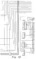
- FIGs. 9b-9l are production combine parts and are shown for purposes of clarity.
- GUI 200 is implemented by the data acquisition/actuator control (DAAC) computer 62.
- GUI 200 includes switches, digital input and output devices and indicator lights relating to concave position, cylinder speed, fan speed, chaffer opening, extension opening and sieve opening.
- DAAC data acquisition/actuator control
- GUI 200 includes switches, digital input and output devices and indicator lights relating to concave position, cylinder speed, fan speed, chaffer opening, extension opening and sieve opening.
- a readout 204 displays the actual value from the sensor associated with the combine function.
- Status lights 206 indicate whether the associated combine function is increasing or decreasing.
- a setpoint select switch 208 can be set to a local position wherein the setpoints are determined manually by the operator via front panel settings and to a neural network position wherein the setpoints are determined by the neural network regardless of the front panel settings.
- a setpoint readout 210 displays the value of the setpoints determined by the neural network.
- a setpoint readout 212 displays the value of the operator determined setpoint associated with the combine function. Also included is a kill or stop button, a stopped or running status indicator and a set of error indicators.
- the computer 62 functions as the GUI 200, and functions with respect to data acquisition, receiving sensor data and with respect to closed loop control of the adjustment actuators.
- the computer 62 is programmed to perform these functions using commercially available LabView II computer software from National Instruments. Programming in this language is very similar to constructing an analog wiring diagram. The various graphical elements of this language are selected from the LabView menus and incorporated into the GUI 200. With this software it is possible to program the computer 62, complete with GUI 200, without an extensive amount of custom programming.
- a graphical user interface is implemented by the computer 64, also using the commercially available LabView II computer software.
- the GUI of FIGs. 4a-4c allows the operator to input data to the neural network emulation and to view the effects of changes of the process adjustments on the process outputs.
- the GUI 300 of FIG. 4a shows the screen used by the operator to enter the operator inputs on the local crop conditions, and to display sensor inputs.
- the threshing condition variable allows the operator to set how hard or easy threshing conditions are.
- the growing condition variable allows the operator to set how wet or dry are the growing or field conditions are.
- the GUI 310 of FIG. 4b allows the operator to define the relative weighting to be applied to the output parameters during the global optimization.
- the GUI 320 of FIG. 4c allows the operator to vary the values of the process adjustments and view the effect on each of the individual output parameters, as well as the "weighted sum" global optimization parameter.
- a neural network 400 is emulated and implemented on the computer 64, also using the commercially available LabView II computer software. This emulated neural network is used by the operator of the combine 10 to optimize the operation of the combine 10.
- Neural network 400 includes inputs for 15 input variables which are scaled to values between -1 and +1, then fed into each of five separate neural networks 402-410, one network for each output parameter.
- the output parameters are grain damage, walker loss, cleaner loss, dockage and unthreshed crop. These outputs are displayed on GUI 320.
- Network 402 includes a first layer with six neurons dmg17-dmg22, a second layer with three neurons dmg23-dmg25 and a third or output layer with a single output neuron dmg26.
- Network 404 includes a first layer with six neurons sep17-sep22, a second layer with three neurons sep23-sep25 and a third or output layer with a single output neuron sep26.
- Network 406 includes a first layer with six neurons loss17-loss22, a second layer with three neurons loss23-loss25 and a third or output layer with a single output neuron loss26.
- Network 408 includes a first layer with six neurons dock17-dock22, a second layer with three neurons dock23-dock25 and a third or output layer with a single output neuron dock26.
- Network 410 includes a first layer with six neurons thr17-thr22, a second layer with three neurons thr23-thr25 and a third or output layer with a single output neuron thr26.
- FIG. 6 is representative of the first layer neurons.
- Each first layer neuron includes 15 inputs EXT, a set of weights W associated with the various inputs and arithmetic means for determining an output signal as a function of the inputs and the weights.
- FIG. 7 is representative of the second layer neurons.
- Each second layer neuron includes 6 inputs EXT, a set of weights W associated with the various inputs and arithmetic means for determining an output signal as a function of the inputs and the weights.
- FIG. 8 is representative of the third or output layer neurons.
- Each third or output layer neuron includes 3 inputs EXT, a set of weights W associated with the various inputs and arithmetic means for determining an output signal as a function of the inputs and the weights.
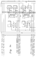
- FIGs 12a-12d are combined to form a block diagram of the closed-loop data acquisition/control computer 62 which receives the desired combine adjustment settings from the neural network emulator computer 64, sets the combine adjusters and actuators and senses the actual condition of the combine adjusters and actuators.
- Each individual neuron within the network is similar to the classic representation of a neuron, with the inputs being multiplied by a weight, summed together, and the sum passed through a squashing function, in this case a hyperbolic tangent.
- the neural network 400 is the result of a multiple part training process described below and it functions as an accurate model of the operation of the combine 10. This model can be exercised to determine the optimum setting of the combine controls. To save time during the training process, the network 400 may be trained off-line on a small workstation computer (not shown), then the connection weights of the trained network were transferred to the emulation program running on the laptop computer 64.
- a neural network with the architecture of neural network 400 is first trained to function as a general model of the operation of the combine 10.
- the training data consists of many examples specifying the process inputs and the corresponding outputs. These examples are selected as representative of normal combine operation, and are characterized by setting the inputs for local condition A and local condition B equal to zero.
- the network 400 is then trained with this general training data using a conventional back-propagation training algorithm.
- the training data is supplemented with an additional set of examples representing some specific local condition.
- the neural network 400 is then retrained on this combined data set using the same back-propagation training algorithm.
- the network can be trained to represent multiple local conditions by adding additional local data sets to the set of training examples, each with a unique coding.
- the trained neural network functions as a general combine model when the inputs for the local conditions inputs are both set equal to zero, and functions as a model of some specific local condition when the local condition inputs match the encoding of some local data set contained within the training data.
- the neural network 400 By limiting the number of connections within the neural network 400, it is possible to control the degree of independence between the local models and the general model. With fewer connections, the models tend to have a degree of dependence. In cases where there is a large amount of data available for the general model, and only limited data for a local model, this property provides a method for knowledge inheritance from the general model to the local model.
- the limited degrees of freedom within the neural network are used to model the relationships in which the data indicates explicit differences between the general and the local model. For areas of the local model in which no explicit relationship is given by the data, the limited degrees of freedom force the local model to inherit the relationships contained in the general model.
- the neural network 400 disclosed herein is trained with a general set of data to function as a general model of a machine or process for example of the combine 10 and is trained with a combined set of data including the general set of data and a local set of data to function as a local model or submodel of the machine or process.
- the neural network 400 has an architecture in which the degrees of freedom available for forming models are constrained by the limited number of nodes in the hidden layers. The result is that this neural network 400 is able to accurately function as a general model of the machine or process, but it has insufficient degrees of freedom for the submodels to function completely independent of the general model.
- the functioning of the submodels is partially dependent upon the functioning as the general model, and the submodels will deviate from the general model with respect to local training data which differs from the general training data, but will have properties similar to the general model where the local training data does not contradict the general training data.
- the general model may be trained from data taken from a variety of sources, including test data on combines 10 operating under typical conditions and numerical representations of expert heuristics.
- the submodel training is done by operating the combine 10 under specific local conditions and making several local measurements of the combine 10 in operation, noting both the input and output parameters. Typically four to eight measurements for each distinct local condition are sufficient. Replicate sets of these local examples are added to the set of general training cases so that the number of new examples represents at least 10-20% of the total training cases.
- the local condition inputs are used as indicators to inform the network 400 whether a given data set represents a general condition or a specific local condition.
- This local condition input is set to zero for general model training and operation, and is set to some non-zero value for a given local condition.
- Several different local conditions might be keyed to various values of this local condition input.
- the network 400 that had been previously trained with the general data set, is given further training on the enhanced or combined data set, it forms numerically accurate submodels of the local harvesting processes represented by the local data.
- These local process models incorporate the specific relationships and numerical values that were contained in the local data, and inherit characteristics from the general model which were not explicitly contained in the local data. This ability allows the network 400 to mimic human-like decision making and generalization. This capability also produces a process model which can be easily and locally adapted to satisfy specific local needs.
- an operator can manually and systematically adjust the six operator controls via GUI 200 of FIG. 3 to optimize the outputs (minimize the weighted sum on GUI 320 of FIG. 4c) of the combine 10 as determined by the relative importance or weight of the combine outputs set via GUI 310 of FIG. 4b.
- This can be done utilizing a repetitive, "one-variable-at-a-time” technique, or by utilizing a well known optimization technique such as gradient descent optimization.
- a numerically accurate, neural network based process model can also form the basis of an automatic combine adjustment controller.
- Several techniques are well known in the art for integrating a model into a process optimization routine. One example would be to perform a gradient search optimization using the model to predict the effect of each change in adjustments. Such optimization techniques could be easily automated by the addition of computer software optimization algorithm.
- the accuracy of the overall optimization/control strategy could be enhanced by the addition of feedback sensors for some of the process outputs. This technique would lessen the level of accuracy required by the local model, and would perhaps permit the process optimization to be performed from the general model itself without local calibration.
- the above also provides: a technique for controlling and optimizing an entire process simultaneously, rather than attempting to control isolated sub-systems; a technique to fuse knowledge from a variety of sources into a single model of a general process; a simple technique for transforming a general model into numerically accurate submodels of a process under specific local conditions. This local model can then be used for process optimization.
- the generalization process used in this technique forms models which are similar to those obtained by skilled human operators operating under similar conditions. This provides the possibility of replacing skilled human operators with computer-based controllers for complex process control.
- the system is capable of continuous self-improvement. As information becomes available it can be easily incorporated into the model. Over time, the specific knowledge available from human experts, either about the total process or about process subsystems, can be accumulated and integrated into the system.
Abstract
Description
- The invention relates to a control system which utilizes a neural network, and more particularly, to such a control system for a combine harvester.
- Combine grain harvesters are complex machines and carry out a complex process that currently requires human supervisory control. The many adjustments built into a combine harvester provide versatility, but also make set-up and operation of the machine very difficult, even for experienced operators. For nearly 30 years, researchers have attempted to control sub-systems of the harvesting process with traditional forms of automatic controls. Examples include automatic feedrate controls, threshing cylinder speed controls and cleaning fan controls. More recently, attempts have been made to model or control the harvesting process with rule-based expert systems. However, none of these proposed solutions have proven successful in the marketplace. One reason for this lack of success is that interactions exist between sub-systems. Effective optimization requires consideration of the entire machine or process rather than isolated sub-systems.
- Accordingly, an object of this invention is to provide a neural network based control system for a combine harvester.
- A further object of the invention is to provide such a control system which can respond to and control the entire machine rather than only portions or sub-systems of the machine.
- A further object of the invention is to provide such a control system which can function in response to a general or typical set of conditions and which can function in response to different specific local conditions.
- Another object of the invention is to provide such a control system which can function in response to different specific local conditions while retaining the ability to function in response the general or typical set of conditions.
- These and other objects are achieved by the present invention, which includes a neural network with an architecture including a plurality of neurons, including hidden layers. Each of the neurons in one of the layers has a plurality of inputs. At least one of these inputs is a local condition input which is set equal to zero while the network is trained with a general set of data. The network is then re-trained or receives additional training on an extended data set containing the general set of data, characterized by zero values for the local condition inputs, and data on specific local conditions, characterized by non-zero values for the local condition inputs. The resulting trained network will function as a general model and as a local model and the local model will function partially dependent upon the general model. This trained neural network is combined with sensors, actuators, a control and communications computer and with a user interface to function as a combine control system.
- It follows a brief description of the drawings which show one embodiment of the invention and in which:
- FIG. 1
- is a side view of a combine schematically illustrating its major systems and components;
- FIG. 2
- is a schematic block diagram of the control system of the present invention;
- FIG. 3
- illustrates the graphical user interface implemented by the data acquisition/actuator control (DAAC) computer of FIG. 2;
- FIGs. 4a-4c
- illustrate the graphical user interfaces implemented by an inventive neural network emulation computer of FIG. 2;
- FIG. 5a
- shows the arrangement of FIGs. 5b-5f;
- FIGs. 5b-5f
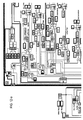
- are combined to form a top level schematic diagram illustrating neural network emulator of FIG. 2;
- FIG. 6
- illustrates a neuron which is representative of the neurons which are in the first layer of the neural network of FIGs. 5b-5f;
- FIG. 7
- illustrates a neuron which is representative of the neurons which are in the second layer of the neural network of FIGs. 5b-5f;
- FIG. 8
- illustrates a neuron which is representative of the neurons which are in the third or output layer of the neural network of FIGs. 5b-5f;
- FIG. 9a
- shows the arrangement of FIGs. 9b-9l;
- FIGs. 9b-9l
- are combined to form a wiring diagram illustrating the senors, relays and actuators of the present invention;
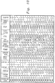
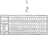
- FIGs. 10 and 11
- illustrate in tabular form experimentally determined data for a first local condition;
- FIGs. 12a-12d
- shows a block diagram of a closed-loop data acquisition/control computer and
- FIG. 13
- shows the position of neurons in the hierarchy of the network.
- FIG. 1 illustrates a machine as an
agricultural combine 10, such as a John Deere Model 9500 production combine harvester, such as described in US Patent No. 4,967,863. Thecombine 10 has achassis 12 and groundengaging wheels engaging wheels 14 are driven byhydraulic motor 18 located between thewheels Harvesting platform 22 extends forwardly from thechassis 12 of thecombine 10 and is used for harvesting a crop in a field. After harvesting, the crop is then directed throughfeeder house 24 and into thecombine 10.Clean grain compartment 26 is located behind the operator'scab 20 at the top of thecombine 10. Behindcompartment 26 is transverseinternal combustion engine 28 which is the prime mover of thecombine 10, powering the propulsion means, the harvesting means, and the threshing and separating means. Theinternal combustion engine 28 is provided with a driving means 30 for powering the various usage assemblies. - Between the sides of the
combine 10, which form thechassis 12 of thecombine 10, is located the threshing and separating means. The threshing and separating means separates the grain from the straw and chaff of the harvested crop. Thefeeder house 24 directs the harvested grain to threshing means 31 which comprises rotating transverse threshingcylinder 32, transverse concave 34, and rotatingbeater 38. As the crop passes betweencylinder 32 and concave 34, grain and chaff fall through the concave 34 to pan 36 and the remaining straw and unseparated grain is advanced tobeater 38. - After threshing, the straw in the crop is advanced to separating
means 39. The main elements of the separating means 39 arestraw walkers 40, and cleaningshoe assembly 48. Frombeater 38 the crop is advanced to theoscillating straw walkers 40 which direct the straw to the rear of thecombine 10 where it is returned to the field bystraw spreader 44. Grain and chaff falling through thestraw walkers 40 falls onto oscillating slantedpan 46 which directs the grain and chaff to pan 36. The grain and chaff are directed frompan 36 by overhead auger assemblies to cleaningshoe assembly 48 which is used to separate the chaff from the grain. The grain and chaff falling onto thechaffer 47,sieve 49 andchaffer extension 51 of thecleaning shoe assembly 48 encounters an air stream fromfan 50 which blows the lighter chaff out of the rear of thecombine 10 while the heavier grain falls through the cleaningshoe assembly 48 and into cleangrain receiving auger 52. -
Auger 52 directs the clean grain to a clean grain elevator (not shown) which in turn directs the grain to cleangrain compartment 26. Tailings, that is unthreshed heads of grain, fall into tailings auger 54 which directs the unthreshed heads back to the threshingcylinder 32 and concave 34. When theclean grain compartment 26 is to be unloaded, transverse unloading augers 56 direct the grain to the side of thecompartment 26 from where it comes into contact with a vertical unloading auger (not shown) which directs the clean grain through unloadingtube 58. During an unloading operation,tube 58 would normally be extended outwardly from the side of thecombine 10 so that clean grain can be more readily directed into a wagon or truck. It should be noted that the arrangement of the threshing and separating elements is well known, and that this invention is directed to a control system for controlling the operation of these elements and thecombine 10. - The cleaning
shoe assembly 48 of thecombine 10 is equipped with three sieving surfaces. The upper surface, orchaffer 47, is adjusted to retain the large pieces of material other than grain, "MOG", while allowing the grain and small pieces of chaff to pass through. Thesieve 49 is located under thechaffer 47. Thesieve 49 is adjusted to remove the small pieces of chaff, while allowing the cleaned grain to pass through. At the rear of thecleaning shoe assembly 48 is the chaffer-extension 51. Its purpose is to scavenge any remaining grain or unthreshed heads of grain before the trash is discharged from thecombine 10. Each of these sieving surfaces is composed of adjustable louvers (not shown). A combination of louver opening and fan speed is used to completely clean the grain with a minimum of grain loss. In the production model of thecombine 10, the operator must leave the operator'scab 20, and make these louver adjustments from the ground at the rear of the machine. - Referring now to FIG. 2, a
control system 60 includes a variety of sensors and actuators, a data acquisition system, a data acquisition/actuator control computer (DAAC) 62 to control the actuators, and a second or neural network emulator computer (NN) 64 to run the neural network process model. - The data acquisition/
control computer 62 functions as a closed loop controller for the adjustment actuators, gathers and processes sensor data, and feeds data to and from theneural network computer 64. Thecomputer 62 is preferably an Apple Macintosh portable computer with 8MB of RAM and a 40 MB hard disk, is relatively small, includes a flat LCD screen, is battery-powered, and is preferably mounted in the operator'scab 20. Thesecond computer 64 functions as a neural network processor or emulator, and is preferably a Macintosh portable or laptop computer, also located in the cab of thecombine 10.Computers -
Computer 62 includes an internal modem (not shown) which is connected by an RS-422data bus 66 to an RS-485-to-RS-422 converter 68 (preferably model number M1200), which is in turn connected to an RS-485data bus 70.Bus 70, is in turn connected to a pair of frequency-to-RS-485converters 72 and 74 (preferably model number M1602) and to an RS-232-to-RS-485 converter 76 (model 485C0R from B & B Electronics Mfg.. Ottawa, IL).Converters - A SCSI port of
computer 62 is connected toSCSI bus 78.Bus 78 is connected to a pair of 8-channel MacADIOSdigital output devices 80 and to a pair of 8-channel MacADIOS analog input devices 82.Devices 80 are connected to arack 84 of output signal conditioning circuits for 16 digital output relays. Devices 82 are connected to arack 86 of input signal conditioning circuits for 16 analog input channels. The SCSIdigital output devices 80 are preferably model GWI-8DIO, and the SCSI analog input devices 82 are preferably model GWI-8AIN, both from GW Instruments, Somerville, MA. The digital outputsignal condition modules 84 are preferably model ODC-05, and the analoginput conditioning modules 86 are preferably model MB-31-03, all from Keithly Metrabyte, Taunton, MA. Power is supplied by a 12 VDC/110 VAC inverter. - A threshing cylinder
speed adjusting actuator 90 is connected tomodule 84 via a speed increase relay and a speed decrease relay. A cleaning fanspeed adjusting actuator 92 is connected tomodule 84 via a fan speed increase relay and a fan speed decrease relay. A concaveclearance adjusting actuator 94 is connected tomodule 84 via a clearance increase relay and a clearance decrease relay. Electro-hydraulic orelectric actuators - The production model harvester comes already equipped with
digital tachometers cylinder 32 and the speed of thecleaner fan 50. The speed signals coming into thesetachometers control computer 62, they are fed first into the frequency-to-RS-485converters bus 70, converter 68 andbus 66 to the modem port of thecomputer 62. - The system also includes a
grain moisture sensor 100 such as a "MoistureTrac"model 5010 manufactured by Shivvers Inc., Corydon, IA, with an RS-232 communications port installed by the manufacturer, and agrain temperature sensor 101. The grain moisture and grain temperature readings pass throughconverter 76,bus 70, then through converter 68 andbus 66 to thecomputer 62.Sensors clean grain compartment 26 of thecombine 10. - An ambient relative humidity sensor 118 (such as a model CT-827-D-X21 sensor from Hy-Cal Corporation, El Monte, CA) provides an analog signal which is applied directly to one of the Analog/Digital input channels of the
rack 86. - Time-of-day signals are obtained from the internal clock (not shown) of the
data acquisition computer 62. - The control system of the present invention includes a
chaffer adjusting actuator 104, a cleaner extension adjusting actuator 106 and asieve adjusting actuator 108. Like actuators 90-94, each of actuators 104-108 is connected tomodule 84 by a corresponding pair of relays. Preferably, these actuators are ball-screw electric actuators, such as Warner Electric ElecTrak model S24-17A8-02, and are mounted on the stationary frame (not shown) of thecombine 10, and connected to the corresponding production adjustment linkage through flexible cables (not shown). The shaking motion of thecleaning shoe assembly 48 is absorbed in the flexible cables, thus extending the life of the actuators 104-108. - Because of hysteresis due to wind-up in the cables and tolerance stack-up from the adjustment linkage joints, it is not possible to accurately control the louver position by monitoring the position of the actuators. To solve this problem, three accurate
rotary potentiometers chaffer 47, thesieve 49, and thechaffer extension 51 and provide corresponding louver position feedback signals. Because of the severe vibration and dust, a sealed and contactless sensor is preferred, such as model CP-2UK-R potentiometers commercially available from Midori. - An oil-filled
linear potentiometer 116, such as model L010-100 from ETI, Oceanside, CA, is used to provide a position feedback signal representing the clearance between the threshingcylinder 32 and the concave 34. Such an oil-filled version is reliable in a very dusty environment. - A
feedrate sensor 120 is installed near the top of the clean grain elevator (not shown) of thecombine 10 to measure the grain feedrate. Thisfeedrate sensor 120 may be an infrared or photo-electric sensor such as described in GB Patent Specification 1,506,329, published 5 April 1978 or a weight sensitive flow meter such as described in US Patent No. 4,765,190, issued 23 August 1988. The analog output of thesensor 118 is fed into one of the A/D input channels ofmodule 86. For further information relating to the arrangement of the electrical relay modules, rocker switches, sensors and actuators, reference is hereby made to FIGs. 9a-9l and the following part list.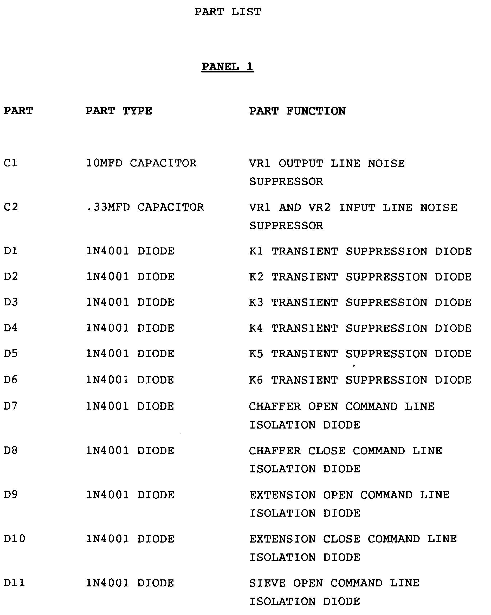


CHAFFER ACTUATOR ASSEMBLY PART PART TYPE PART FUNCTION CHAFFER ASSEMBLY MODIFIED PRODUCTION PART J5 6 PIN WEATHER PAK SERIES INTERCONNECTS SIGNALS AND EXCITATION TO CHAFFER, EXTENSION, AND SIEVE ASSEMBLIES J6 2 PIN WEATHER PAK SERIES SUPPLIES 12 VOLTS TO CHAFFER POSITION MOTOR MOTOR WARNER S2417A8-02 POSITIONS CHAFFER PUSH/PULL CABLE CONNECTS MOTOR TO CHAFFER ASSEMBLY FEEDBACK SENSOR MIDORI CP2US REPORTS CHAFFER POSITION EXTENSION ACTUATOR ASSEMBLY PART PART TYPE PART FUNCTION EXTENSION ASSEMBLY MODIFIED PRODUCTION PART J7 3 PIN WEATHER PAK SERIES INTERCONNECTS SIGNALS AND EXCITATION TO CHAFFER, EXTENSION, AND SIEVE ASSEMBLIES J8 2 PIN WEATHER PAK SERIES SUPPLIES 12 VOLTS TO EXTENSION POSITION MOTOR MOTOR WARNER S2417A8-02 POSITIONS EXTENSION PUSH/PULL CABLE CONNECTS MOTOR TO EXTENSION ASSEMBLY FEEDBACK SENSOR MIDORI CP2US REPORTS EXTENSION POSITION SIEVE ACTUATOR ASSEMBLY PART PART TYPE PART FUNCTION SIEVE ASSEMBLY MODIFIED PRODUCTION PART J5 6 PIN WEATHER PAK SERIES INTERCONNECTS SIGNALS AND EXCITATION TO CHAFFER, EXTENSION, AND SIEVE ASSEMBLIES J9 2 PIN WEATHER PAK SERIES SUPPLIES 12 VOLTS TO SIEVE POSITION MOTOR MOTOR WARNER S2417A8-02 POSITIONS SIEVE PUSH/PULL CABLE CONNECTS MOTOR TO SIEVE ASSEMBLY FEEDBACK SENSOR MIDORI CP2US REPORTS SIEVE POSITION CONCAVE POSITION ACTUATOR ASSEMBLY PART PART TYPE PART FUNCTION POT LINEAR ACTION POTENTIOMETER REPORT CONCAVE POSITION RS 485 BUS INTERFACE MODULES PART PART TYPE PART FUNCTION M1602 (C) KEATHLEY M1602 CONVERTS PRODUCTION CYLINDER SPEED SIGNAL TO AN RS 485 OUTPUT M1602 (F) KEATHLEY M1602 CONVERTS PRODUCTION FAN SPEED SIGNAL TO AN RS 485 OUTPUT 485COR B & B ELECTRONICS CONVERTS RS 232 SIGNAL FROM MOISTURE TRAC TO RS 485 OUTPUT GRAIN MOISTURE SAMPLING SYSTEM PART PART TYPE PART FUNCTION MODEL 5010 SHIVVERS MOISTURE TRAC SAMPLES GRAIN ENTERING GRAIN TANK AND REPORTS MOISTURE CONTENT 
- Other parts and circuits shown on FIGs. 9b-9l are production combine parts and are shown for purposes of clarity.
- Referring now to FIG. 3, a graphical user interface (GUI) 200 is implemented by the data acquisition/actuator control (DAAC)
computer 62.GUI 200 includes switches, digital input and output devices and indicator lights relating to concave position, cylinder speed, fan speed, chaffer opening, extension opening and sieve opening. For each of these combine functions theGUI 200 includes an auto/manual switch 202 so that the operator can select manual control of the associated actuator or automatic, closed loop control of the associated actuator. Areadout 204 displays the actual value from the sensor associated with the combine function.Status lights 206 indicate whether the associated combine function is increasing or decreasing. A setpointselect switch 208 can be set to a local position wherein the setpoints are determined manually by the operator via front panel settings and to a neural network position wherein the setpoints are determined by the neural network regardless of the front panel settings. Asetpoint readout 210 displays the value of the setpoints determined by the neural network. Asetpoint readout 212 displays the value of the operator determined setpoint associated with the combine function. Also included is a kill or stop button, a stopped or running status indicator and a set of error indicators. - The
computer 62 functions as theGUI 200, and functions with respect to data acquisition, receiving sensor data and with respect to closed loop control of the adjustment actuators. Thecomputer 62 is programmed to perform these functions using commercially available LabView II computer software from National Instruments. Programming in this language is very similar to constructing an analog wiring diagram. The various graphical elements of this language are selected from the LabView menus and incorporated into theGUI 200. With this software it is possible to program thecomputer 62, complete withGUI 200, without an extensive amount of custom programming. - For more detailed information concerning the program which causes the
computer 62 to perform as desired, reference is made to the appropriate portions of the graphical computer program listing included in FIGs 12a-12d. This graphical computer program listing is in the LabView II graphical language. - Referring now to FIGs. 4a-4c, a graphical user interface (GUI) is implemented by the
computer 64, also using the commercially available LabView II computer software. The GUI of FIGs. 4a-4c allows the operator to input data to the neural network emulation and to view the effects of changes of the process adjustments on the process outputs. TheGUI 300 of FIG. 4a shows the screen used by the operator to enter the operator inputs on the local crop conditions, and to display sensor inputs. The threshing condition variable allows the operator to set how hard or easy threshing conditions are. The growing condition variable allows the operator to set how wet or dry are the growing or field conditions are. TheGUI 310 of FIG. 4b allows the operator to define the relative weighting to be applied to the output parameters during the global optimization. The GUI 320 of FIG. 4c allows the operator to vary the values of the process adjustments and view the effect on each of the individual output parameters, as well as the "weighted sum" global optimization parameter. - Referring now to FIGs. 5a-5f, a
neural network 400 is emulated and implemented on thecomputer 64, also using the commercially available LabView II computer software. This emulated neural network is used by the operator of thecombine 10 to optimize the operation of thecombine 10. -
Neural network 400 includes inputs for 15 input variables which are scaled to values between -1 and +1, then fed into each of five separate neural networks 402-410, one network for each output parameter. The output parameters are grain damage, walker loss, cleaner loss, dockage and unthreshed crop. These outputs are displayed on GUI 320. -
Network 402 includes a first layer with six neurons dmg17-dmg22, a second layer with three neurons dmg23-dmg25 and a third or output layer with a single output neuron dmg26.Network 404 includes a first layer with six neurons sep17-sep22, a second layer with three neurons sep23-sep25 and a third or output layer with a single output neuron sep26. Network 406 includes a first layer with six neurons loss17-loss22, a second layer with three neurons loss23-loss25 and a third or output layer with a single output neuron loss26.Network 408 includes a first layer with six neurons dock17-dock22, a second layer with three neurons dock23-dock25 and a third or output layer with a single output neuron dock26.Network 410 includes a first layer with six neurons thr17-thr22, a second layer with three neurons thr23-thr25 and a third or output layer with a single output neuron thr26. - FIG. 6 is representative of the first layer neurons. Each first layer neuron includes 15 inputs EXT, a set of weights W associated with the various inputs and arithmetic means for determining an output signal as a function of the inputs and the weights.
- FIG. 7 is representative of the second layer neurons. Each second layer neuron includes 6 inputs EXT, a set of weights W associated with the various inputs and arithmetic means for determining an output signal as a function of the inputs and the weights.
- FIG. 8 is representative of the third or output layer neurons. Each third or output layer neuron includes 3 inputs EXT, a set of weights W associated with the various inputs and arithmetic means for determining an output signal as a function of the inputs and the weights.
- FIGs 12a-12d are combined to form a block diagram of the closed-loop data acquisition/
control computer 62 which receives the desired combine adjustment settings from the neuralnetwork emulator computer 64, sets the combine adjusters and actuators and senses the actual condition of the combine adjusters and actuators. - Each individual neuron within the network is similar to the classic representation of a neuron, with the inputs being multiplied by a weight, summed together, and the sum passed through a squashing function, in this case a hyperbolic tangent.
- The
neural network 400 is the result of a multiple part training process described below and it functions as an accurate model of the operation of thecombine 10. This model can be exercised to determine the optimum setting of the combine controls. To save time during the training process, thenetwork 400 may be trained off-line on a small workstation computer (not shown), then the connection weights of the trained network were transferred to the emulation program running on thelaptop computer 64. - A neural network with the architecture of
neural network 400 is first trained to function as a general model of the operation of thecombine 10. The training data consists of many examples specifying the process inputs and the corresponding outputs. These examples are selected as representative of normal combine operation, and are characterized by setting the inputs for local condition A and local condition B equal to zero. Thenetwork 400 is then trained with this general training data using a conventional back-propagation training algorithm. - Next the training data is supplemented with an additional set of examples representing some specific local condition. To distinguish the local data from the general data, examples from a given local condition are given a unique coding using the local condition inputs. For example, all data from one specific local condition might have the coding local condition A = 1 and local condition B = 0. The
neural network 400 is then retrained on this combined data set using the same back-propagation training algorithm. The network can be trained to represent multiple local conditions by adding additional local data sets to the set of training examples, each with a unique coding. - The result is that the trained neural network functions as a general combine model when the inputs for the local conditions inputs are both set equal to zero, and functions as a model of some specific local condition when the local condition inputs match the encoding of some local data set contained within the training data.
- By limiting the number of connections within the
neural network 400, it is possible to control the degree of independence between the local models and the general model. With fewer connections, the models tend to have a degree of dependence. In cases where there is a large amount of data available for the general model, and only limited data for a local model, this property provides a method for knowledge inheritance from the general model to the local model. The limited degrees of freedom within the neural network are used to model the relationships in which the data indicates explicit differences between the general and the local model. For areas of the local model in which no explicit relationship is given by the data, the limited degrees of freedom force the local model to inherit the relationships contained in the general model. - Stated another way, the
neural network 400 disclosed herein is trained with a general set of data to function as a general model of a machine or process for example of thecombine 10 and is trained with a combined set of data including the general set of data and a local set of data to function as a local model or submodel of the machine or process. Theneural network 400 has an architecture in which the degrees of freedom available for forming models are constrained by the limited number of nodes in the hidden layers. The result is that thisneural network 400 is able to accurately function as a general model of the machine or process, but it has insufficient degrees of freedom for the submodels to function completely independent of the general model. Instead, the functioning of the submodels is partially dependent upon the functioning as the general model, and the submodels will deviate from the general model with respect to local training data which differs from the general training data, but will have properties similar to the general model where the local training data does not contradict the general training data. - The general model may be trained from data taken from a variety of sources, including test data on
combines 10 operating under typical conditions and numerical representations of expert heuristics. The submodel training is done by operating thecombine 10 under specific local conditions and making several local measurements of thecombine 10 in operation, noting both the input and output parameters. Typically four to eight measurements for each distinct local condition are sufficient. Replicate sets of these local examples are added to the set of general training cases so that the number of new examples represents at least 10-20% of the total training cases. - As described earlier, the local condition inputs are used as indicators to inform the
network 400 whether a given data set represents a general condition or a specific local condition. This local condition input is set to zero for general model training and operation, and is set to some non-zero value for a given local condition. Several different local conditions might be keyed to various values of this local condition input. When thenetwork 400, that had been previously trained with the general data set, is given further training on the enhanced or combined data set, it forms numerically accurate submodels of the local harvesting processes represented by the local data. These local process models incorporate the specific relationships and numerical values that were contained in the local data, and inherit characteristics from the general model which were not explicitly contained in the local data. This ability allows thenetwork 400 to mimic human-like decision making and generalization. This capability also produces a process model which can be easily and locally adapted to satisfy specific local needs. - With such a numerically accurate submodel of the harvesting process, it is possible to quickly and easily predict the effect of various combine adjustments on combine performance. This is far superior to the current practice of making a change in adjustment, stopping the machine and dismounting, observing the effect, making an additional change, and so on. When implemented on a portable computer, this process model could provide the basis for manually optimizing the harvesting process.
- For example, an operator can manually and systematically adjust the six operator controls via
GUI 200 of FIG. 3 to optimize the outputs (minimize the weighted sum on GUI 320 of FIG. 4c) of thecombine 10 as determined by the relative importance or weight of the combine outputs set viaGUI 310 of FIG. 4b. This can be done utilizing a repetitive, "one-variable-at-a-time" technique, or by utilizing a well known optimization technique such as gradient descent optimization. - A numerically accurate, neural network based process model can also form the basis of an automatic combine adjustment controller. Several techniques are well known in the art for integrating a model into a process optimization routine. One example would be to perform a gradient search optimization using the model to predict the effect of each change in adjustments. Such optimization techniques could be easily automated by the addition of computer software optimization algorithm.
- The accuracy of the overall optimization/control strategy could be enhanced by the addition of feedback sensors for some of the process outputs. This technique would lessen the level of accuracy required by the local model, and would perhaps permit the process optimization to be performed from the general model itself without local calibration.
- In the case of a combine harvester, there are six process outputs to be optimized, but sensors are available for only one of these outputs. If accurate sensors were available for all outputs, optimization of the harvester adjustments could be done with traditional control techniques. Since feedback data on the outputs are not available, knowledge processing techniques are being used to form an accurate process model. An accurate model can then provide accurate estimates of the process outputs, which are used for open-loop optimization of the process.
- In addition to its applicability for combine harvester process control, the general techniques outlined above have broad application to a variety of process control and optimization problems.
- The above also provides:
a technique for controlling and optimizing an entire process simultaneously, rather than attempting to control isolated sub-systems;
a technique to fuse knowledge from a variety of sources into a single model of a general process;
a simple technique for transforming a general model into numerically accurate submodels of a process under specific local conditions. This local model can then be used for process optimization. - The generalization process used in this technique forms models which are similar to those obtained by skilled human operators operating under similar conditions. This provides the possibility of replacing skilled human operators with computer-based controllers for complex process control.
- The system is capable of continuous self-improvement. As information becomes available it can be easily incorporated into the model. Over time, the specific knowledge available from human experts, either about the total process or about process subsystems, can be accumulated and integrated into the system.
- While the present invention has been described in conjunction with a specific embodiment, it is understood that many alternatives, modifications and variations will be apparent to those skilled in the art in light of the foregoing description. For example, the software/computer-based graphical user interfaces, the data acquisition/actuator controller and the neural network emulator of the present invention could be all be replaced by functionally equivalent hardware systems. Accordingly, this invention is intended to embrace all such alternatives, modifications and variations which fall within the spirit and scope of the appended claims.
Claims (8)
- A neural network (400) for generating an output signal as a function of a plurality of input signals and having a plurality of neurons (dmg17-dmg26; sep17-sep26;loss17-loss26;dock17-dock26;thr17-thr26), characterized by:
the neural network (400) being trained with a general set of data to function as a general model of a machine (10) or process and being trained with a combined set of data including the general set of data and a local set of data to function as a local model of the machine (10) or process, the neural network (400) having an architecture and a number of neurons (dmg17-dmg26; sep17-sep26;loss17-loss26;dock17-dock26;thr17-thr26) such that its functioning as the local model is partially dependent upon its functioning as the general model. - A neural network according to claim 1, comprising:
a plurality of neurons (dmg17-dmg26; sep17-sep26;loss17-loss26;dock17-dock26;thr17-thr26) in a layer, each of said neurons (dmg 17-dmg26; sep17-sep26;loss17-loss26;dock17-dock26;thr17-thr26) having a plurality of inputs, at least one of said inputs for each of the neurons (dmg17-dmg26; sep17-sep26;loss17-loss26;dock17-dock26;thr17-thr26) comprising a local condition input which is set equal to a first value while the network (400) is trained with the general set of data and which set equal to a second value when the network (400) is trained with a combination of the general set of data with the local set of data. - A machine control system, in particular of a machine (10) being a combine, having a neural network (400), characterized by:
the neural network (400) being trained with a general set of data to function as a general model of the machine (10) and being trained with a combined set of data including the general set of data and a local set of data to function as a submodel of the machine ((10)) with respect to conditions represented by the local set of data. - A machine control system according to claim 3, wherein:
the neural network (400) has an architecture and a number of neurons (dmg17-dmg26; sep17-sep26;loss17-loss26;dock17-dock26;thr17-thr26) such that its functioning as the submodel is partially dependent upon its functioning as the general model. - A machine control system according to claims 3 or 4, comprising:
a plurality of actuators (90, 92, 94, 104, 106, 108), each for controlling a particular function of the machine (10) in response to an actuator control signal;
a plurality of feedback sensors, each generating a feedback signal representing a condition of a corresponding one of the actuators (90, 92, 94, 104, 106, 108);
a plurality of machine parameter sensors, each generating a parameter sensor signal representing a parameter of the machine (10);
a plurality of condition sensors, each generating a condition sensor signal representing a condition which influences operation of the machine (10);
an actuator control unit for generating the actuator control signals as a function of the feedback signals and as a function of input signals;
the neural network (400) trained to function as a general model of the machine (10) and trained to function as a submodel with respect to a set of local condition data, the neural network (400) generating response signals representing the responses of the machine (10) to varying conditions; and
a data communication system comprising means for communicating the feedback signals to the actuator control unit, means for communicating the sensor signals to the neural network (400), and means for communicating the response signals to the neural network (400), the neural network (400) and the actuator control unit cooperating to control operation of the machine 10. - A machine control system according to any of the claims 3 - 5, whereas the machine (10) is a combine which has a plurality of controllable components, the components comprising a variable speed threshing cylinder, a concave having a variable clearance, a variable speed cleaning fan, a sieve, a chaffer and a cleaner extension, the control system comprising:
a set of actuators (90, 92, 94, 104, 106, 108), each for controlling a corresponding one of the components in response to a corresponding actuator control signal;
a set of feedback sensors, each generating a feedback signal representing a condition of a corresponding one of the actuators (90, 92, 94, 104, 106, 108);
a set of combine parameter sensors, each generating a parameter sensor signal representing a parameter of the machine (10)/combine;
a set of condition sensors, each generating a condition sensor signal representing a condition which influences operation of the machine 10/combine;
an actuator control unit for generating the actuator control signals as a function of the feedback signals and as a function of input signals;
the neural network (400) trained to function as a general model of the machine (10)/combine and trained to function as a submodel with respect to a set of local condition data, the neural network (400) generating the input signals as a function of the responses of the machine (10)/combine to varying conditions; and
a data communication system comprising means for communicating the feedback signals to the actuator control unit, means for communicating the sensor signals to the neural network (400), and means for communicating the input signals to the neural network (400), the neural network (400) and the actuator control unit cooperating to control operation of the machine (10)/combine. - A machine control system according to claim 5 or 6, wherein the set of condition sensors comprises:
a relative humidity sensor (118);
a grain moisture sensor (100) and
a grain temperature sensor (101). - A machine control system according to claim 6 or 7, wherein the set of combine parameter sensors comprises:
a grain feedrate sensor;
a threshing cylinder speed sensor;
a concave clearance sensor;
a cleaning fan speed sensor;
a sieve position sensor;
a chaffer position sensor; and
a cleaner extension position sensor.
Applications Claiming Priority (2)
| Application Number | Priority Date | Filing Date | Title |
|---|---|---|---|
| US94529392A | 1992-09-10 | 1992-09-10 | |
| US945293 | 1992-09-10 |
Publications (3)
| Publication Number | Publication Date |
|---|---|
| EP0586999A2 true EP0586999A2 (en) | 1994-03-16 |
| EP0586999A3 EP0586999A3 (en) | 1995-03-29 |
| EP0586999B1 EP0586999B1 (en) | 1999-03-17 |
Family
ID=25482924
Family Applications (1)
| Application Number | Title | Priority Date | Filing Date |
|---|---|---|---|
| EP93113807A Expired - Lifetime EP0586999B1 (en) | 1992-09-10 | 1993-08-30 | Neural network based controller for a machine in particular for a combine |
Country Status (6)
| Country | Link |
|---|---|
| US (1) | US5586033A (en) |
| EP (1) | EP0586999B1 (en) |
| JP (1) | JP3478855B2 (en) |
| AU (1) | AU658066B2 (en) |
| CA (1) | CA2105842C (en) |
| DE (1) | DE69323943T2 (en) |
Cited By (23)
| Publication number | Priority date | Publication date | Assignee | Title |
|---|---|---|---|---|
| EP0928554A1 (en) * | 1998-01-07 | 1999-07-14 | CLAAS Selbstfahrende Erntemaschinen GmbH | System for regulation of a self-propelled harvesting machine |
| EP0775612A3 (en) * | 1993-06-28 | 2001-02-07 | New Holland Belgium N.V. | Process for the control of self-propelled agricultural harvesting machines |
| EP1321024A1 (en) * | 2001-12-18 | 2003-06-25 | CLAAS Selbstfahrende Erntemaschinen GmbH | Method and device for optimising the operation of an agricultural vehicle |
| EP1504648A1 (en) | 2003-08-08 | 2005-02-09 | CLAAS Selbstfahrende Erntemaschinen GmbH | Method and device for operating working machines |
| DE19514223B4 (en) * | 1995-04-15 | 2005-06-23 | Claas Kgaa Mbh | Method for optimizing the use of agricultural machinery |
| EP1056328B2 (en) † | 1998-02-20 | 2007-10-03 | CLAAS Selbstfahrende Erntemaschinen GmbH | Combine with a device for automatic cleaning regulation |
| US7452267B2 (en) | 2007-03-20 | 2008-11-18 | Cnh America Llc | System and method for automatically deslugging an agricultural combine |
| EP2042019A2 (en) * | 2007-09-27 | 2009-04-01 | CLAAS Selbstfahrende Erntemaschinen GmbH | Agricultural work vehicle |
| US7632179B2 (en) | 2005-08-01 | 2009-12-15 | Cnh America Llc | System and method for detecting combine rotor slugging |
| EP2132974A1 (en) * | 2008-06-12 | 2009-12-16 | CLAAS Selbstfahrende Erntemaschinen GmbH | Agricultural harvester |
| US20120004813A1 (en) * | 2010-07-01 | 2012-01-05 | Joachim Baumgarten | Method for adjusting at least one working unit of a self-propelled harvesting machine |
| EP2401904B1 (en) | 2010-07-01 | 2016-01-06 | CLAAS Selbstfahrende Erntemaschinen GmbH | Driver assistance system for agricultural vehicle |
| EP2987396A1 (en) | 2014-08-21 | 2016-02-24 | Deere & Company | Operator assistance system for an agricultural work machine |
| DE102016207509A1 (en) | 2016-05-02 | 2017-11-02 | Deere & Company | Method and arrangement for optimizing working parameters of a harvester |
| CN108009626A (en) * | 2016-10-27 | 2018-05-08 | 谷歌公司 | It is sparse using the input data in neural computing unit |
| CN109657782A (en) * | 2018-12-14 | 2019-04-19 | 北京中科寒武纪科技有限公司 | Operation method, device and Related product |
| CN110799030A (en) * | 2017-05-30 | 2020-02-14 | 沃尔塔机器人有限责任公司 | Method for controlling soil working device based on image processing and related system |
| EP3178307B1 (en) | 2015-12-07 | 2020-10-07 | CLAAS Selbstfahrende Erntemaschinen GmbH | Agricultural work machine |
| EP3766331A1 (en) * | 2019-07-19 | 2021-01-20 | Deere & Company | Federated harvester control |
| EP3839443B1 (en) * | 2019-12-16 | 2022-06-08 | Sick Ag | Encoder device and method for determining a kinematic value |
| US11379707B2 (en) | 2016-10-27 | 2022-07-05 | Google Llc | Neural network instruction set architecture |
| US11422801B2 (en) | 2016-10-27 | 2022-08-23 | Google Llc | Neural network compute tile |
| WO2022248177A1 (en) * | 2021-05-27 | 2022-12-01 | Robert Bosch Gmbh | Method for operating a hydraulic cylinder of a work machine |
Families Citing this family (101)
| Publication number | Priority date | Publication date | Assignee | Title |
|---|---|---|---|---|
| US5212765A (en) * | 1990-08-03 | 1993-05-18 | E. I. Du Pont De Nemours & Co., Inc. | On-line training neural network system for process control |
| US5923004A (en) * | 1997-12-30 | 1999-07-13 | Otis Elevator Company | Method for continuous learning by a neural network used in an elevator dispatching system |
| US6389884B1 (en) * | 1998-10-08 | 2002-05-21 | Claas Selbstfahrende Erntemaschinen Gmbh | Device and method for measuring the moisture of crop material in agricultural machines |
| US7110526B1 (en) | 1998-10-14 | 2006-09-19 | Rockwell Electronic Commerce Technologies, Llc | Neural network for controlling calls in a telephone switch |
| US6453241B1 (en) * | 1998-12-23 | 2002-09-17 | Rosetta Inpharmatics, Inc. | Method and system for analyzing biological response signal data |
| US6213870B1 (en) | 1999-03-24 | 2001-04-10 | Caterpillar Inc. | Stall prevention system |
| DE19931844A1 (en) * | 1999-07-09 | 2001-01-11 | Claas Selbstfahr Erntemasch | Device for adjusting the sieve opening width on combine harvesters |
| CA2298195A1 (en) | 1999-07-16 | 2001-01-16 | Deere & Company | Cleaning shoe adjustment mechanism for a harvester |
| US6876991B1 (en) | 1999-11-08 | 2005-04-05 | Collaborative Decision Platforms, Llc. | System, method and computer program product for a collaborative decision platform |
| DE10030262A1 (en) | 2000-06-20 | 2002-01-31 | Deere & Co | cleaning device |
| DE10036971A1 (en) * | 2000-07-28 | 2002-02-28 | Siemens Ag | Method for remote diagnosis of a technological process |
| US6591145B1 (en) * | 2000-09-21 | 2003-07-08 | Bechtel Bwxt Idaho, Llc | Systems and methods for autonomously controlling agricultural machinery |
| DE10064356A1 (en) * | 2000-12-21 | 2002-07-11 | Claas Selbstfahr Erntemasch | Device and method for conveying crops in agricultural machines |
| DE10111531A1 (en) * | 2001-03-10 | 2002-09-26 | Deere & Co | Screen for a combine harvester |
| US6632136B2 (en) | 2001-06-05 | 2003-10-14 | Deere & Company | Remote adjustment mechanism for a combine harvester cleaning element |
| US6553300B2 (en) * | 2001-07-16 | 2003-04-22 | Deere & Company | Harvester with intelligent hybrid control system |
| US20030028353A1 (en) * | 2001-08-06 | 2003-02-06 | Brian Gventer | Production pattern-recognition artificial neural net (ANN) with event-response expert system (ES)--yieldshieldTM |
| DE10147733A1 (en) * | 2001-09-27 | 2003-04-10 | Claas Selbstfahr Erntemasch | Method and device for determining a harvester setting |
| US6655351B2 (en) | 2001-10-24 | 2003-12-02 | Deere & Company | Vehicle engine control |
| US7535454B2 (en) * | 2001-11-01 | 2009-05-19 | Immersion Corporation | Method and apparatus for providing haptic feedback |
| US20030088321A1 (en) * | 2001-11-05 | 2003-05-08 | Creger Todd D | Method for compensating for variations in modeled parameters of machines |
| US6726559B2 (en) | 2002-05-14 | 2004-04-27 | Deere & Company | Harvester with control system considering operator feedback |
| GB2410997A (en) * | 2002-11-01 | 2005-08-17 | Immersion Corp | Method and apparatus for providing haptic feedback |
| US8463441B2 (en) | 2002-12-09 | 2013-06-11 | Hudson Technologies, Inc. | Method and apparatus for optimizing refrigeration systems |
| DE10306726A1 (en) * | 2003-02-17 | 2004-09-30 | Claas Selbstfahrende Erntemaschinen Gmbh | Method for optimizing adjustable parameters |
| DE10324045B3 (en) * | 2003-05-27 | 2004-10-14 | Siemens Ag | System characteristics modelling method for dynamic system using similarity analysis for modification of known system characteristics supplied to neural network structure for causality analysis |
| US7194320B2 (en) * | 2003-06-05 | 2007-03-20 | Neuco, Inc. | Method for implementing indirect controller |
| US7519604B2 (en) * | 2003-08-29 | 2009-04-14 | Nokia Corporation | Troubleshooting engine and method for using same |
| KR100543707B1 (en) * | 2003-12-04 | 2006-01-20 | 삼성전자주식회사 | Face recognition method and apparatus using PCA learning per subgroup |
| US7272544B2 (en) * | 2004-01-15 | 2007-09-18 | Honeywell International Inc. | Integrated modeling through symbolic manipulation |
| DE102004011982A1 (en) * | 2004-03-10 | 2005-10-06 | Claas Selbstfahrende Erntemaschinen Gmbh | Dew point sensor for harvesters |
| US8504707B2 (en) * | 2004-12-07 | 2013-08-06 | Cisco Technology, Inc. | Method and system for sending and receiving USB messages over a data network |
| US7644211B2 (en) * | 2004-12-07 | 2010-01-05 | Cisco Technology, Inc. | Method and system for controlling transmission of USB messages over a data network between a USB device and a plurality of host computers |
| DE102005026159A1 (en) * | 2005-06-06 | 2007-01-25 | Claas Selbstfahrende Erntemaschinen Gmbh | Method for controlling a harvesting machine |
| DE102005047335A1 (en) * | 2005-09-30 | 2007-04-12 | Claas Selbstfahrende Erntemaschinen Gmbh | Self-propelled harvester and operating method for it |
| US20070260379A1 (en) * | 2006-05-05 | 2007-11-08 | Congdon Thomas M | Method of operating a machine for conditioning a work material |
| US20070288147A1 (en) * | 2006-05-25 | 2007-12-13 | Reeves Barry H | System and method for indicating to a remote location operation of an auger or the like |
| US8930089B2 (en) * | 2006-05-25 | 2015-01-06 | Barry H. Reeves | System and method for indicating to a remote location operation of an auger or the like |
| US7386380B2 (en) * | 2006-07-31 | 2008-06-10 | Deere & Company | Cotton harvester row unit speed synchronization control |
| US7689309B2 (en) * | 2007-07-03 | 2010-03-30 | Delphi Technologies, Inc. | Method for generating an electro-hydraulic model for control design |
| US8627306B2 (en) * | 2008-08-06 | 2014-01-07 | Caterpillar Inc. | Method and system for updating an information management system configuration |
| FR2958911B1 (en) * | 2010-04-19 | 2012-04-27 | Snecma | METHOD AND SYSTEM FOR MONITORING THE OIL LEVEL CONTAINED IN A RESERVOIR OF AN AIRCRAFT ENGINE |
| US9631964B2 (en) | 2011-03-11 | 2017-04-25 | Intelligent Agricultural Solutions, Llc | Acoustic material flow sensor |
| US10318138B2 (en) * | 2011-03-11 | 2019-06-11 | Intelligent Agricultural Solutions Llc | Harvesting machine capable of automatic adjustment |
| US9629308B2 (en) | 2011-03-11 | 2017-04-25 | Intelligent Agricultural Solutions, Llc | Harvesting machine capable of automatic adjustment |
| US10321624B2 (en) | 2011-03-11 | 2019-06-18 | Intelligent Agriculture Solutions LLC | Air seeder manifold system |
| US9582178B2 (en) | 2011-11-07 | 2017-02-28 | Immersion Corporation | Systems and methods for multi-pressure interaction on touch-sensitive surfaces |
| CN102998973B (en) * | 2012-11-28 | 2016-11-09 | 上海交通大学 | The multi-model Adaptive Control device of a kind of nonlinear system and control method |
| US9198344B2 (en) | 2013-01-09 | 2015-12-01 | Cnh Industrial Canada, Ltd. | Setup wizard for agricultural equipment |
| CN103310272B (en) * | 2013-07-02 | 2016-06-08 | 南京邮电大学 | Based on the DIVA neural network model manner of articulation that sound channel action knowledge base is improved |
| US10085379B2 (en) | 2014-09-12 | 2018-10-02 | Appareo Systems, Llc | Grain quality sensor |
| AU2015314684B2 (en) | 2014-09-12 | 2020-09-03 | Appareo Systems, Llc | Non-image-based grain quality sensor |
| US9706709B2 (en) | 2015-09-10 | 2017-07-18 | Deere & Company | Harvester fan speed control based on yield |
| CN110740635A (en) * | 2017-03-21 | 2020-01-31 | 蓝河技术有限公司 | Combine harvester including machine feedback control |
| JP6673293B2 (en) * | 2017-05-24 | 2020-03-25 | トヨタ自動車株式会社 | Vehicle system |
| US11191215B1 (en) * | 2017-12-28 | 2021-12-07 | Brian G. Robertson | Dynamically operated concave threshing bar |
| RU2693680C9 (en) * | 2018-03-27 | 2019-07-16 | Александр Игоревич Галькевич | An intelligent, integrated digital platform for managing large systems, and a way to manage large systems |
| WO2019226871A1 (en) * | 2018-05-24 | 2019-11-28 | Blue River Technology Inc. | Boom sprayer including machine feedback control |
| CN108934416A (en) * | 2018-07-06 | 2018-12-07 | 巢湖学院 | One kind being based on BP neural network combined harvester multi-parameter operation-control system and method |
| US11641800B2 (en) | 2020-02-06 | 2023-05-09 | Deere & Company | Agricultural harvesting machine with pre-emergence weed detection and mitigation system |
| US11653588B2 (en) | 2018-10-26 | 2023-05-23 | Deere & Company | Yield map generation and control system |
| US11589509B2 (en) | 2018-10-26 | 2023-02-28 | Deere & Company | Predictive machine characteristic map generation and control system |
| US11672203B2 (en) | 2018-10-26 | 2023-06-13 | Deere & Company | Predictive map generation and control |
| US11178818B2 (en) | 2018-10-26 | 2021-11-23 | Deere & Company | Harvesting machine control system with fill level processing based on yield data |
| US11240961B2 (en) | 2018-10-26 | 2022-02-08 | Deere & Company | Controlling a harvesting machine based on a geo-spatial representation indicating where the harvesting machine is likely to reach capacity |
| US11467605B2 (en) | 2019-04-10 | 2022-10-11 | Deere & Company | Zonal machine control |
| US11079725B2 (en) | 2019-04-10 | 2021-08-03 | Deere & Company | Machine control using real-time model |
| US11957072B2 (en) | 2020-02-06 | 2024-04-16 | Deere & Company | Pre-emergence weed detection and mitigation system |
| US11234366B2 (en) | 2019-04-10 | 2022-02-01 | Deere & Company | Image selection for machine control |
| US11778945B2 (en) | 2019-04-10 | 2023-10-10 | Deere & Company | Machine control using real-time model |
| US20200375104A1 (en) * | 2019-05-31 | 2020-12-03 | Deere & Company | Virtual sensor for grain loss in combine harvester |
| US11690320B2 (en) | 2019-07-11 | 2023-07-04 | Deere & Company | Work machine control based on machine capabilities relative to work assignment criteria |
| US11412657B2 (en) * | 2019-10-29 | 2022-08-16 | Landing AI | AI-optimized harvester configured to maximize yield and minimize impurities |
| US11308738B2 (en) * | 2020-01-06 | 2022-04-19 | Deere & Company | Mobile work machine performance detection and control system |
| US11477940B2 (en) | 2020-03-26 | 2022-10-25 | Deere & Company | Mobile work machine control based on zone parameter modification |
| CN111751133B (en) * | 2020-06-08 | 2021-07-27 | 南京航空航天大学 | Intelligent fault diagnosis method of deep convolutional neural network model based on non-local mean embedding |
| DE102020117941A1 (en) | 2020-07-07 | 2022-01-13 | Grimme Landmaschinenfabrik Gmbh & Co. Kg | Method for adapting a process model for operating one of several working machines, in particular root crop harvesting machines |
| DE102020117940A1 (en) | 2020-07-07 | 2022-01-13 | Grimme Landmaschinenfabrik Gmbh & Co. Kg | Method for operating one of several working machines, in particular root crop harvesting machines |
| CN112013203B (en) * | 2020-07-18 | 2021-09-24 | 淮阴工学院 | Pipe network detection system based on DRNN neural network |
| US11895948B2 (en) | 2020-10-09 | 2024-02-13 | Deere & Company | Predictive map generation and control based on soil properties |
| US11864483B2 (en) | 2020-10-09 | 2024-01-09 | Deere & Company | Predictive map generation and control system |
| US11675354B2 (en) | 2020-10-09 | 2023-06-13 | Deere & Company | Machine control using a predictive map |
| US11889788B2 (en) | 2020-10-09 | 2024-02-06 | Deere & Company | Predictive biomass map generation and control |
| US11474523B2 (en) | 2020-10-09 | 2022-10-18 | Deere & Company | Machine control using a predictive speed map |
| US11825768B2 (en) | 2020-10-09 | 2023-11-28 | Deere & Company | Machine control using a predictive map |
| US11946747B2 (en) | 2020-10-09 | 2024-04-02 | Deere & Company | Crop constituent map generation and control system |
| US11844311B2 (en) | 2020-10-09 | 2023-12-19 | Deere & Company | Machine control using a predictive map |
| US11871697B2 (en) | 2020-10-09 | 2024-01-16 | Deere & Company | Crop moisture map generation and control system |
| US11927459B2 (en) | 2020-10-09 | 2024-03-12 | Deere & Company | Machine control using a predictive map |
| US11849672B2 (en) | 2020-10-09 | 2023-12-26 | Deere & Company | Machine control using a predictive map |
| US11849671B2 (en) | 2020-10-09 | 2023-12-26 | Deere & Company | Crop state map generation and control system |
| US11845449B2 (en) | 2020-10-09 | 2023-12-19 | Deere & Company | Map generation and control system |
| US11650587B2 (en) | 2020-10-09 | 2023-05-16 | Deere & Company | Predictive power map generation and control system |
| US11592822B2 (en) | 2020-10-09 | 2023-02-28 | Deere & Company | Machine control using a predictive map |
| US11874669B2 (en) | 2020-10-09 | 2024-01-16 | Deere & Company | Map generation and control system |
| US11727680B2 (en) | 2020-10-09 | 2023-08-15 | Deere & Company | Predictive map generation based on seeding characteristics and control |
| US11635765B2 (en) | 2020-10-09 | 2023-04-25 | Deere & Company | Crop state map generation and control system |
| US11711995B2 (en) | 2020-10-09 | 2023-08-01 | Deere & Company | Machine control using a predictive map |
| US11889787B2 (en) | 2020-10-09 | 2024-02-06 | Deere & Company | Predictive speed map generation and control system |
| CN113837399B (en) * | 2021-10-26 | 2023-05-30 | 医渡云(北京)技术有限公司 | Training method, device, system, storage medium and equipment for federal learning model |
| CN116859830B (en) * | 2023-03-27 | 2024-01-26 | 福建天甫电子材料有限公司 | Production management control system for electronic grade ammonium fluoride production |
Citations (3)
| Publication number | Priority date | Publication date | Assignee | Title |
|---|---|---|---|---|
| US4967863A (en) * | 1987-05-15 | 1990-11-06 | Deere & Company | Compact combine drive system |
| JPH04252302A (en) * | 1991-01-28 | 1992-09-08 | Kawasaki Steel Corp | Control model identifying method and control method for continuous rolling mill |
| GB2266602A (en) * | 1992-04-16 | 1993-11-03 | Inventio Ag | Lift traffic predicting system |
Family Cites Families (17)
| Publication number | Priority date | Publication date | Assignee | Title |
|---|---|---|---|---|
| US4495577A (en) * | 1982-08-06 | 1985-01-22 | Deere & Company | Model reference adaptive implement control |
| US4527241A (en) * | 1982-08-30 | 1985-07-02 | Sperry Corporation | Automatic combine harvester adjustment system |
| JPS6165307A (en) * | 1984-09-05 | 1986-04-03 | Konishiroku Photo Ind Co Ltd | Control method of photographic emulsion manufacture process by nonlinear approximation |
| GB2186777B (en) * | 1986-02-20 | 1989-11-22 | Massey Ferguson Services Nv | Ground speed control |
| US4874963A (en) * | 1988-02-11 | 1989-10-17 | Bell Communications Research, Inc. | Neuromorphic learning networks |
| GB8814936D0 (en) * | 1988-06-23 | 1988-07-27 | Ford New Holland Nv | Combine ground speed control system |
| US4967544A (en) * | 1989-01-05 | 1990-11-06 | Deere & Company | Automatic speed control system for a harvesting assembly |
| JP2656637B2 (en) * | 1989-11-22 | 1997-09-24 | 株式会社日立製作所 | Process control system and power plant process control system |
| CA2031765C (en) * | 1989-12-08 | 1996-02-20 | Masahide Nomura | Method and system for performing control conforming with characteristics of controlled system |
| JPH04211802A (en) * | 1990-07-25 | 1992-08-03 | Toshiba Corp | Neural network device |
| US5142612A (en) * | 1990-08-03 | 1992-08-25 | E. I. Du Pont De Nemours & Co. (Inc.) | Computer neural network supervisory process control system and method |
| US5282261A (en) * | 1990-08-03 | 1994-01-25 | E. I. Du Pont De Nemours And Co., Inc. | Neural network process measurement and control |
| US5167009A (en) * | 1990-08-03 | 1992-11-24 | E. I. Du Pont De Nemours & Co. (Inc.) | On-line process control neural network using data pointers |
| US5251144A (en) * | 1991-04-18 | 1993-10-05 | Texas Instruments Incorporated | System and method utilizing a real time expert system for tool life prediction and tool wear diagnosis |
| US5268834A (en) * | 1991-06-24 | 1993-12-07 | Massachusetts Institute Of Technology | Stable adaptive neural network controller |
| US5253329A (en) * | 1991-12-26 | 1993-10-12 | The United States Of America As Represented By The Administrator Of The National Aeronautics And Space Administration | Neural network for processing both spatial and temporal data with time based back-propagation |
| US5353207A (en) * | 1992-06-10 | 1994-10-04 | Pavilion Technologies, Inc. | Residual activation neural network |
-
1993
- 1993-05-31 AU AU39930/93A patent/AU658066B2/en not_active Ceased
- 1993-08-30 DE DE69323943T patent/DE69323943T2/en not_active Expired - Fee Related
- 1993-08-30 EP EP93113807A patent/EP0586999B1/en not_active Expired - Lifetime
- 1993-09-09 CA CA002105842A patent/CA2105842C/en not_active Expired - Fee Related
- 1993-09-10 JP JP22610593A patent/JP3478855B2/en not_active Expired - Fee Related
-
1995
- 1995-06-06 US US08/466,957 patent/US5586033A/en not_active Expired - Lifetime
Patent Citations (3)
| Publication number | Priority date | Publication date | Assignee | Title |
|---|---|---|---|---|
| US4967863A (en) * | 1987-05-15 | 1990-11-06 | Deere & Company | Compact combine drive system |
| JPH04252302A (en) * | 1991-01-28 | 1992-09-08 | Kawasaki Steel Corp | Control model identifying method and control method for continuous rolling mill |
| GB2266602A (en) * | 1992-04-16 | 1993-11-03 | Inventio Ag | Lift traffic predicting system |
Non-Patent Citations (1)
| Title |
|---|
| PATENT ABSTRACTS OF JAPAN, unexamined applications, P field, vol. 17, no. 29, January 20, 1993 THE PATENT OFFICE JAPANESE GOVERNMENT page 161 P 1472; & JP-A-04 252 302 (KAWASAKI STEEL CORP.) * |
Cited By (38)
| Publication number | Priority date | Publication date | Assignee | Title |
|---|---|---|---|---|
| EP0775612A3 (en) * | 1993-06-28 | 2001-02-07 | New Holland Belgium N.V. | Process for the control of self-propelled agricultural harvesting machines |
| DE19514223B4 (en) * | 1995-04-15 | 2005-06-23 | Claas Kgaa Mbh | Method for optimizing the use of agricultural machinery |
| DE19800238C1 (en) * | 1998-01-07 | 1999-08-26 | Claas Selbstfahr Erntemasch | System for setting a self-propelled harvester |
| US6205384B1 (en) | 1998-01-07 | 2001-03-20 | Claas Selbstfahrende Erntemaschinen Gmbh | System for setting operating parameters of a harvesting machine |
| EP0928554A1 (en) * | 1998-01-07 | 1999-07-14 | CLAAS Selbstfahrende Erntemaschinen GmbH | System for regulation of a self-propelled harvesting machine |
| EP1056328B2 (en) † | 1998-02-20 | 2007-10-03 | CLAAS Selbstfahrende Erntemaschinen GmbH | Combine with a device for automatic cleaning regulation |
| EP1321024A1 (en) * | 2001-12-18 | 2003-06-25 | CLAAS Selbstfahrende Erntemaschinen GmbH | Method and device for optimising the operation of an agricultural vehicle |
| US7266415B2 (en) | 2003-08-08 | 2007-09-04 | Claas Selbstfahrende Erntemaschinen Gmbh | Method of and apparatus for operating working machines |
| EP1504648A1 (en) | 2003-08-08 | 2005-02-09 | CLAAS Selbstfahrende Erntemaschinen GmbH | Method and device for operating working machines |
| US7632179B2 (en) | 2005-08-01 | 2009-12-15 | Cnh America Llc | System and method for detecting combine rotor slugging |
| US7452267B2 (en) | 2007-03-20 | 2008-11-18 | Cnh America Llc | System and method for automatically deslugging an agricultural combine |
| US7520806B2 (en) | 2007-03-20 | 2009-04-21 | Cnh America Llc | System for automatically deslugging an agricultural combine |
| EP2042019A2 (en) * | 2007-09-27 | 2009-04-01 | CLAAS Selbstfahrende Erntemaschinen GmbH | Agricultural work vehicle |
| EP2042019A3 (en) * | 2007-09-27 | 2009-09-09 | CLAAS Selbstfahrende Erntemaschinen GmbH | Agricultural work vehicle |
| EP2132974A1 (en) * | 2008-06-12 | 2009-12-16 | CLAAS Selbstfahrende Erntemaschinen GmbH | Agricultural harvester |
| US20120004813A1 (en) * | 2010-07-01 | 2012-01-05 | Joachim Baumgarten | Method for adjusting at least one working unit of a self-propelled harvesting machine |
| US9220196B2 (en) * | 2010-07-01 | 2015-12-29 | Claas Selbstfahrende Erntemaschinen Gmbh | Method for adjusting at least one working unit of a self-propelled harvesting machine |
| EP2401904B1 (en) | 2010-07-01 | 2016-01-06 | CLAAS Selbstfahrende Erntemaschinen GmbH | Driver assistance system for agricultural vehicle |
| EP2401904B2 (en) † | 2010-07-01 | 2021-03-24 | CLAAS Selbstfahrende Erntemaschinen GmbH | Driver assistance system for agricultural vehicle |
| EP2987396A1 (en) | 2014-08-21 | 2016-02-24 | Deere & Company | Operator assistance system for an agricultural work machine |
| US9707972B2 (en) | 2014-08-21 | 2017-07-18 | Deere & Company | Operator assistance system for an agricultural machine |
| DE102014216593A1 (en) | 2014-08-21 | 2016-02-25 | Deere & Company | Operator assistance system for an agricultural working machine |
| EP3178307B1 (en) | 2015-12-07 | 2020-10-07 | CLAAS Selbstfahrende Erntemaschinen GmbH | Agricultural work machine |
| DE102016207509A1 (en) | 2016-05-02 | 2017-11-02 | Deere & Company | Method and arrangement for optimizing working parameters of a harvester |
| EP3242257A1 (en) | 2016-05-02 | 2017-11-08 | Deere & Company | Method and arrangement for optimising operating parameters of a harvesting machine |
| US11379707B2 (en) | 2016-10-27 | 2022-07-05 | Google Llc | Neural network instruction set architecture |
| CN108009626A (en) * | 2016-10-27 | 2018-05-08 | 谷歌公司 | It is sparse using the input data in neural computing unit |
| US11816480B2 (en) | 2016-10-27 | 2023-11-14 | Google Llc | Neural network compute tile |
| US11816045B2 (en) | 2016-10-27 | 2023-11-14 | Google Llc | Exploiting input data sparsity in neural network compute units |
| US11106606B2 (en) | 2016-10-27 | 2021-08-31 | Google Llc | Exploiting input data sparsity in neural network compute units |
| US11422801B2 (en) | 2016-10-27 | 2022-08-23 | Google Llc | Neural network compute tile |
| CN110799030A (en) * | 2017-05-30 | 2020-02-14 | 沃尔塔机器人有限责任公司 | Method for controlling soil working device based on image processing and related system |
| CN109657782A (en) * | 2018-12-14 | 2019-04-19 | 北京中科寒武纪科技有限公司 | Operation method, device and Related product |
| CN109657782B (en) * | 2018-12-14 | 2020-10-27 | 安徽寒武纪信息科技有限公司 | Operation method, device and related product |
| EP3766331A1 (en) * | 2019-07-19 | 2021-01-20 | Deere & Company | Federated harvester control |
| EP3839443B1 (en) * | 2019-12-16 | 2022-06-08 | Sick Ag | Encoder device and method for determining a kinematic value |
| US11698386B2 (en) | 2019-12-16 | 2023-07-11 | Sick Ag | Encoder device and method of determining a kinematic value |
| WO2022248177A1 (en) * | 2021-05-27 | 2022-12-01 | Robert Bosch Gmbh | Method for operating a hydraulic cylinder of a work machine |
Also Published As
| Publication number | Publication date |
|---|---|
| AU3993093A (en) | 1994-03-17 |
| CA2105842C (en) | 1998-11-03 |
| DE69323943D1 (en) | 1999-04-22 |
| JPH06176179A (en) | 1994-06-24 |
| DE69323943T2 (en) | 1999-08-12 |
| AU658066B2 (en) | 1995-03-30 |
| JP3478855B2 (en) | 2003-12-15 |
| CA2105842A1 (en) | 1994-03-11 |
| EP0586999B1 (en) | 1999-03-17 |
| EP0586999A3 (en) | 1995-03-29 |
| US5586033A (en) | 1996-12-17 |
Similar Documents
| Publication | Publication Date | Title |
|---|---|---|
| EP0586999B1 (en) | Neural network based controller for a machine in particular for a combine | |
| US6553300B2 (en) | Harvester with intelligent hybrid control system | |
| EP3453239B1 (en) | System for optimizing agricultural machine settings | |
| CN111837626A (en) | Information inference for agronomic data generation in sugarcane applications | |
| CA1330113C (en) | Combine ground speed control system | |
| EP3001890B1 (en) | Automatic tuning of an intelligent combine | |
| US6119442A (en) | Combine setting autoadjust with machine vision | |
| US5577373A (en) | Agricultural vehicle including a system for automatically moving an implement and improved ground height sensing to a predetermined operating position | |
| DK1446997T4 (en) | Process for optimizing adjustable parameters. | |
| US5469694A (en) | Agricultural vehicle including a system for automatically moving an implement to a predetermined operating position | |
| US4513562A (en) | Combine ground speed control system | |
| AU2014201449A1 (en) | Harvester with fuzzy control system for detecting steady crop processing state | |
| EP3542616B1 (en) | Combine harvester with fan speed adjust | |
| Gundoshmian et al. | Application of artificial neural network in prediction of the combine harvester performance | |
| CN108934416A (en) | One kind being based on BP neural network combined harvester multi-parameter operation-control system and method | |
| CN111837602B (en) | Harvester control system with knife bar load sensing | |
| CN102929146B (en) | Device and method for realizing model reference adaptive control on operation speed of combine harvester | |
| JP2953956B2 (en) | Combine | |
| EP3744167B1 (en) | Virtual sensor for grain loss in combine harvester | |
| CA1129977A (en) | Control of harvesters | |
| KR0127876B1 (en) | Treshing & sorting equipment of grain in combine | |
| JP3143329B2 (en) | Thickness detection equipment for threshing and sorting equipment | |
| Li et al. | An Improved Fuzzy Logic Control Method for Combine Harvester’s Cleaning System | |
| Peschke et al. | Model Predictive Control for Combine Harvesters using Geospatial Data | |
| JP2949033B2 (en) | Threshing sorting controller |
Legal Events
| Date | Code | Title | Description |
|---|---|---|---|
| PUAI | Public reference made under article 153(3) epc to a published international application that has entered the european phase |
Free format text: ORIGINAL CODE: 0009012 |
|
| AK | Designated contracting states |
Kind code of ref document: A2 Designated state(s): BE DE FR GB IT |
|
| PUAL | Search report despatched |
Free format text: ORIGINAL CODE: 0009013 |
|
| AK | Designated contracting states |
Kind code of ref document: A3 Designated state(s): BE DE FR GB IT |
|
| 17P | Request for examination filed |
Effective date: 19950217 |
|
| 17Q | First examination report despatched |
Effective date: 19961115 |
|
| GRAG | Despatch of communication of intention to grant |
Free format text: ORIGINAL CODE: EPIDOS AGRA |
|
| GRAG | Despatch of communication of intention to grant |
Free format text: ORIGINAL CODE: EPIDOS AGRA |
|
| GRAH | Despatch of communication of intention to grant a patent |
Free format text: ORIGINAL CODE: EPIDOS IGRA |
|
| RAP1 | Party data changed (applicant data changed or rights of an application transferred) |
Owner name: DEERE & COMPANY |
|
| GRAH | Despatch of communication of intention to grant a patent |
Free format text: ORIGINAL CODE: EPIDOS IGRA |
|
| GRAA | (expected) grant |
Free format text: ORIGINAL CODE: 0009210 |
|
| AK | Designated contracting states |
Kind code of ref document: B1 Designated state(s): BE DE FR GB IT |
|
| REF | Corresponds to: |
Ref document number: 69323943 Country of ref document: DE Date of ref document: 19990422 |
|
| ET | Fr: translation filed | ||
| PLBE | No opposition filed within time limit |
Free format text: ORIGINAL CODE: 0009261 |
|
| STAA | Information on the status of an ep patent application or granted ep patent |
Free format text: STATUS: NO OPPOSITION FILED WITHIN TIME LIMIT |
|
| 26N | No opposition filed | ||
| REG | Reference to a national code |
Ref country code: GB Ref legal event code: IF02 |
|
| PGFP | Annual fee paid to national office [announced via postgrant information from national office to epo] |
Ref country code: FR Payment date: 20050817 Year of fee payment: 13 |
|
| PGFP | Annual fee paid to national office [announced via postgrant information from national office to epo] |
Ref country code: BE Payment date: 20050902 Year of fee payment: 13 |
|
| PGFP | Annual fee paid to national office [announced via postgrant information from national office to epo] |
Ref country code: DE Payment date: 20060719 Year of fee payment: 14 |
|
| PGFP | Annual fee paid to national office [announced via postgrant information from national office to epo] |
Ref country code: GB Payment date: 20060825 Year of fee payment: 14 |
|
| PG25 | Lapsed in a contracting state [announced via postgrant information from national office to epo] |
Ref country code: BE Free format text: LAPSE BECAUSE OF NON-PAYMENT OF DUE FEES Effective date: 20060831 |
|
| PGFP | Annual fee paid to national office [announced via postgrant information from national office to epo] |
Ref country code: IT Payment date: 20060831 Year of fee payment: 14 |
|
| REG | Reference to a national code |
Ref country code: FR Ref legal event code: ST Effective date: 20070430 |
|
| BERE | Be: lapsed |
Owner name: *DEERE & CY Effective date: 20060831 |
|
| GBPC | Gb: european patent ceased through non-payment of renewal fee |
Effective date: 20070830 |
|
| PG25 | Lapsed in a contracting state [announced via postgrant information from national office to epo] |
Ref country code: FR Free format text: LAPSE BECAUSE OF NON-PAYMENT OF DUE FEES Effective date: 20060831 |
|
| PG25 | Lapsed in a contracting state [announced via postgrant information from national office to epo] |
Ref country code: DE Free format text: LAPSE BECAUSE OF NON-PAYMENT OF DUE FEES Effective date: 20080301 |
|
| PG25 | Lapsed in a contracting state [announced via postgrant information from national office to epo] |
Ref country code: GB Free format text: LAPSE BECAUSE OF NON-PAYMENT OF DUE FEES Effective date: 20070830 |
|
| PG25 | Lapsed in a contracting state [announced via postgrant information from national office to epo] |
Ref country code: IT Free format text: LAPSE BECAUSE OF NON-PAYMENT OF DUE FEES Effective date: 20070830 |