EP0588509A2 - Stereoscopic display apparatus - Google Patents
Stereoscopic display apparatus Download PDFInfo
- Publication number
- EP0588509A2 EP0588509A2 EP93306623A EP93306623A EP0588509A2 EP 0588509 A2 EP0588509 A2 EP 0588509A2 EP 93306623 A EP93306623 A EP 93306623A EP 93306623 A EP93306623 A EP 93306623A EP 0588509 A2 EP0588509 A2 EP 0588509A2
- Authority
- EP
- European Patent Office
- Prior art keywords
- display
- light modulating
- space light
- units
- virtual
- Prior art date
- Legal status (The legal status is an assumption and is not a legal conclusion. Google has not performed a legal analysis and makes no representation as to the accuracy of the status listed.)
- Granted
Links
- 239000007787 solid Substances 0.000 claims abstract description 23
- 238000006243 chemical reaction Methods 0.000 claims abstract description 6
- 239000004973 liquid crystal related substance Substances 0.000 claims description 44
- 210000002858 crystal cell Anatomy 0.000 claims description 15
- 239000011159 matrix material Substances 0.000 claims description 8
- 230000005540 biological transmission Effects 0.000 claims description 6
- 230000001678 irradiating effect Effects 0.000 claims description 3
- 238000010586 diagram Methods 0.000 description 25
- 230000004048 modification Effects 0.000 description 5
- 238000012986 modification Methods 0.000 description 5
- 230000000007 visual effect Effects 0.000 description 4
- 230000008859 change Effects 0.000 description 3
- 238000000034 method Methods 0.000 description 3
- 230000003287 optical effect Effects 0.000 description 3
- 239000004065 semiconductor Substances 0.000 description 3
- XMWRBQBLMFGWIX-UHFFFAOYSA-N C60 fullerene Chemical compound C12=C3C(C4=C56)=C7C8=C5C5=C9C%10=C6C6=C4C1=C1C4=C6C6=C%10C%10=C9C9=C%11C5=C8C5=C8C7=C3C3=C7C2=C1C1=C2C4=C6C4=C%10C6=C9C9=C%11C5=C5C8=C3C3=C7C1=C1C2=C4C6=C2C9=C5C3=C12 XMWRBQBLMFGWIX-UHFFFAOYSA-N 0.000 description 2
- 230000008878 coupling Effects 0.000 description 2
- 238000010168 coupling process Methods 0.000 description 2
- 238000005859 coupling reaction Methods 0.000 description 2
- 229910003472 fullerene Inorganic materials 0.000 description 2
- 239000011521 glass Substances 0.000 description 2
- 238000004519 manufacturing process Methods 0.000 description 2
- 239000000758 substrate Substances 0.000 description 2
- 230000000694 effects Effects 0.000 description 1
- 230000004907 flux Effects 0.000 description 1
- 230000005484 gravity Effects 0.000 description 1
- 238000001093 holography Methods 0.000 description 1
- 230000006872 improvement Effects 0.000 description 1
- 238000005070 sampling Methods 0.000 description 1
- 238000001228 spectrum Methods 0.000 description 1
Images


Classifications
-
- G—PHYSICS
- G09—EDUCATION; CRYPTOGRAPHY; DISPLAY; ADVERTISING; SEALS
- G09F—DISPLAYING; ADVERTISING; SIGNS; LABELS OR NAME-PLATES; SEALS
- G09F9/00—Indicating arrangements for variable information in which the information is built-up on a support by selection or combination of individual elements
- G09F9/30—Indicating arrangements for variable information in which the information is built-up on a support by selection or combination of individual elements in which the desired character or characters are formed by combining individual elements
- G09F9/35—Indicating arrangements for variable information in which the information is built-up on a support by selection or combination of individual elements in which the desired character or characters are formed by combining individual elements being liquid crystals
-
- G—PHYSICS
- G03—PHOTOGRAPHY; CINEMATOGRAPHY; ANALOGOUS TECHNIQUES USING WAVES OTHER THAN OPTICAL WAVES; ELECTROGRAPHY; HOLOGRAPHY
- G03H—HOLOGRAPHIC PROCESSES OR APPARATUS
- G03H1/00—Holographic processes or apparatus using light, infrared or ultraviolet waves for obtaining holograms or for obtaining an image from them; Details peculiar thereto
- G03H1/04—Processes or apparatus for producing holograms
- G03H1/08—Synthesising holograms, i.e. holograms synthesized from objects or objects from holograms
-
- G—PHYSICS
- G03—PHOTOGRAPHY; CINEMATOGRAPHY; ANALOGOUS TECHNIQUES USING WAVES OTHER THAN OPTICAL WAVES; ELECTROGRAPHY; HOLOGRAPHY
- G03H—HOLOGRAPHIC PROCESSES OR APPARATUS
- G03H1/00—Holographic processes or apparatus using light, infrared or ultraviolet waves for obtaining holograms or for obtaining an image from them; Details peculiar thereto
- G03H1/22—Processes or apparatus for obtaining an optical image from holograms
- G03H1/2294—Addressing the hologram to an active spatial light modulator
-
- G—PHYSICS
- G03—PHOTOGRAPHY; CINEMATOGRAPHY; ANALOGOUS TECHNIQUES USING WAVES OTHER THAN OPTICAL WAVES; ELECTROGRAPHY; HOLOGRAPHY
- G03H—HOLOGRAPHIC PROCESSES OR APPARATUS
- G03H1/00—Holographic processes or apparatus using light, infrared or ultraviolet waves for obtaining holograms or for obtaining an image from them; Details peculiar thereto
- G03H1/26—Processes or apparatus specially adapted to produce multiple sub- holograms or to obtain images from them, e.g. multicolour technique
- G03H1/268—Holographic stereogram
-
- G—PHYSICS
- G03—PHOTOGRAPHY; CINEMATOGRAPHY; ANALOGOUS TECHNIQUES USING WAVES OTHER THAN OPTICAL WAVES; ELECTROGRAPHY; HOLOGRAPHY
- G03H—HOLOGRAPHIC PROCESSES OR APPARATUS
- G03H1/00—Holographic processes or apparatus using light, infrared or ultraviolet waves for obtaining holograms or for obtaining an image from them; Details peculiar thereto
- G03H1/26—Processes or apparatus specially adapted to produce multiple sub- holograms or to obtain images from them, e.g. multicolour technique
- G03H2001/2605—Arrangement of the sub-holograms, e.g. partial overlapping
- G03H2001/262—Arrangement of the sub-holograms, e.g. partial overlapping not in optical contact
-
- G—PHYSICS
- G03—PHOTOGRAPHY; CINEMATOGRAPHY; ANALOGOUS TECHNIQUES USING WAVES OTHER THAN OPTICAL WAVES; ELECTROGRAPHY; HOLOGRAPHY
- G03H—HOLOGRAPHIC PROCESSES OR APPARATUS
- G03H2225/00—Active addressable light modulator
- G03H2225/60—Multiple SLMs
Definitions
- the invention relates to a space light modulating apparatus and a stereoscopic display apparatus, for example for use in a rewritable hologram stereoscopic display.
- a stereoscopic display is a method of enabling a structure such as depth, thickness, or the like of a 3-dimensional object to be easily visually understood. Such a stereoscopic display is largely demanded in the display field of the structure designed by a CAD or the like or the display field of a medical image.
- the stereoscopic display has a feeling of a reality and is impressive as compared with the 2-dimensional display and is also used in the display for amusement in an amusement park, a movie, or the like.
- a conventional rewritable hologram stereoscopic display apparatus is realized by using, for example, an acoustic optical element (AOM) for generating a calculated 1-dimensional interference fringe, a rotary mirror, a galvano mirror, a reducing lens, and the like (refer to "Practical Holography VI, #1212-20", SPIE Proc., Vol. 1212, 1990). Since such an apparatus has mechanical movable portions, however, there is a drawback such that it is difficult to realize a large screen and to miniaturize the apparatus.
- AOM acoustic optical element
- a pixel density of the ordinary liquid crystal display apparatus is equal to a value on the order of about 103 per line and is not so fine, so that it is difficult to express an interference fringe of a high spatial frequency, namely, a phase distribution. That is, in order to display a solid image in front of the space light modulating apparatus or in a wide visual field, a space light modulating element which can display an interference fringe at a high spatial frequency is needed. According to the pixel density of the present liquid crystal display apparatus, however, there is a problem such that an interference fringe at a high spatial frequency cannot be produced.
- embodiments of the invention may provide a space light modulating apparatus which can properly display a solid image by a phase distribution at a low spatial frequency.
- an interference fringe as a phase distribution may be produced on a space light modulating apparatus in which the phase distribution display surface has an arc-like curved surface and a solid image is displayed at a position near the center of the arc.
- a solid image thus, may be stereoscopically displayed at a low spatial frequency.
- the phase display surface forming the curved surface may be an imaginary surface and a plurality of flat space light modulating units each having a predetermined area are arranged along the imaginary surface, thereby forming a phase distribution display surface.
- the space light modulating apparatus may have a plurality of flat space light modulating units each having a predetermined area for performing a wave front conversion while setting the position of a cross point of the normal line from the virtual display surface into a producing position of a solid image are arranged along the virtual display surface having a non-plane shape, for example, a cylindrical surface or a spherical surface to display the phase distribution.
- Embodiments of the invention may provide a stereoscopic display apparatus in which a phase distribution of a virtual object is calculated and a space light modulating apparatus is driven and a solid image is displayed is provided.
- the stereoscopic display apparatus may comprise: phase distribution calculating means for calculating a phase distribution (interference fringe) on the basis of 3-dimensional image information to be displayed; and display driving means for displaying the phase distribution obtained by the phase distribution calculating means to each of flat space light modulating units of the space light modulating apparatus and for allowing a solid image to be displayed by the wave front conversion by irradiation of a reference light.
- Space light modulating apparatus and stereoscopic display apparatus even in case of producing the same solid image, may express the solid image by a diffraction of a low angle by producing an interference fringe to the space light modulating apparatus of a curved surface rather than producing an interference fringe to the space light modulating apparatus of a flat surface. Since the diffraction angle is low, the spatial frequency of the interference fringe can be also set to a low frequency. Particularly, by setting a position near the cross point of the normal line from the curved surface of the space light modulating apparatus (near the center of the spherical surface or arc) into a producing position of the solid image, a stereoscopic display can be performed by the diffraction of the lowest angle.
- the space light modulating apparatus having a curved surface
- a plurality of flat space light modulating units each having a small area are arranged.
- the display surface of the phase distribution is locally flat, the stereoscopic display can be executed at a spatial frequency that is lower than that in the case where the whole display surface is formed by a flat surface.
- Such a space light modulating apparatus and a stereoscopic display apparatus can be designed to display a solid image at a practical pixel density.
- FIG. 1 shows the first embodiment of the invention.
- a display section 10 is constructed by coupling seven space light modulating units 12-1 to 12-7 by flexible coupling portions 18. By attaching the display section 10 onto a base plate 15, the space light modulating units are arranged along a cylindrical surface having a predetermined radius.
- the space light modulating units 12-1 to 12-7 have a combination structure of liquid crystal display units 14-1 to 14-7 provided on the inside and illuminating units 16-1 to 16-7 provided on the outside, respectively.
- a number of micro liquid crystal cells are arranged in a matrix form in order to display an interference fringe as a calculated phase distribution on the inside.
- a connector unit 20 is attached to the side surface of the space light modulating unit 12-1.
- a signal line 25 from a display driving section 24 is connected to the connector unit 20.
- a phase distribution calculating section 22 is provided for the display driving section 24.
- Fig. 2A is a diagram showing a conventional flat space light modulating apparatus 26.
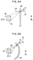
- Fig. 2B is a diagram showing an arc-shaped space light modulating apparatus 40.
- the flat space light modulating apparatus 26 of Fig. 2A in case of displaying a real image 30-1 when it is seen from a visual point 38 for the irradiation of a reference light 28, it is necessary to perform a diffraction at a large angle ⁇ 1 which is decided by a line 34 on the lower side of the real image 30-1 for a normal line 32.
- a phase distribution at a high spatial frequency must be displayed.
- a diffraction angle for the reference light 28 in case of displaying the real image 30-1 at the same position when it is seen from the visual point 38 can be set to a small angle ⁇ 2 for lines 44 and 46 which define both sides of the real image 30-1 from the normal line 42.
- a spatial frequency of an interference fringe as a phase distribution which is produced on the arc surface of the space light modulating apparatus 40 can be set to a low frequency. This point also shall apply to the display of a virtual image shown in each of Figs. 3A and 3B.
- Fig. 5 is a diagram showing liquid crystal display units which are used in the space light modulating units 12-1 to 12-7 in Fig. 1.
- a number of micro liquid crystal cells 58 are arranged in a matrix form on the display surface of the liquid crystal display unit 14.
- Fig. 6 shows another embodiment of the liquid crystal display unit 14 which is used in the embodiment of Fig. 1.
- the embodiment is characterized in that a liquid crystal segment 60 in which a predetermined number of liquid crystal cells 58 are arranged in a matrix form is set to one unit and that a plurality of such liquid crystal segments 60 are two-dimensionally arranged in a matrix form.
- the liquid crystal display unit 14 can be easily manufactured as compared with the case where the liquid crystal cells 58 are arranged on the whole surface as shown in Fig. 5.
- Fig. 7 shows a structure of the liquid crystal display unit.
- the liquid crystal display unit 14 has a uniform transparent electrode 144 subsequent to a glass substrate 140 on the incident surface side. Branched transparent electrodes 146-1 to 146-n constructing one display segment are formed subsequent to a glass substrate 142 on the outgoing side. Orientation films 152 and 154 are provided through insulating layers 148 and 150 subsequent to the transparent electrodes 144 and 146-1 to 146-n. A liquid crystal 160 is provided between the orientation films 152 and 154.
- the liquid crystal display unit 14 is driven so that the voltage corresponding to the calculated phase information is applied to every liquid crystal cells which are decided by the divided electrodes 146-1 to 146-n.
- a refractive index of the liquid crystal cell for the transmitting direction of a reproduction light 162 is changed in accordance with the applied voltage.
- Fig. 8 shows a state of phase modulation with respect to three pixels of the liquid crystal display in Fig. 7 as an example.
- reproduction lights 162-1 to 162-3 comprising, for instance, plane waves having the same phase entered from the left side into pixels 166-1,166-2, and 166-3 which had been driven into different phase states, namely, to different refractive indices.
- phase deviations occur in lights 164-1 to 164-3 upon outgoing. It is ideally demanded that an arbitrary phase within a range of 0 to 2 ⁇ , namely, a range of a length corresponding to the wavelength as an optical distance can be expressed.
- a depth of liquid crystal is decided so as to satisfy conditions such that the product ⁇ n x d of the thickness d and a change ⁇ n in maximum refractive index which can be changed by the applied voltage is equal to a wavelength ⁇ of the reproduction light.
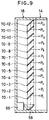
- Fig. 9 shows an embodiment of the illuminating units 16-1 to 16-2 provided on the back side of the space light modulating units 12-1 to 12-7 shown in Fig. 1.
- a laser light source 66 is built in on the lower side of the illuminating unit 16. It is desirable to use a small semiconductor laser as a laser light source 66.
- the semiconductor laser has a light emitting spectrum whose wavelength width is a few nm or less and can reconstruct a clear solid image. As a wavelength, an arbitrary wavelength can be used so long as it lies within a visible light range. It is necessary to consider a wavelength of light source which is used for reconstruction at the stage of calculating a phase distribution of a hologram.
- a semiconductor laser which emits the light of red whose wavelength is on the order of 600 nm, the light of green whose wavelength is on the order of 500 nm, or the light of blue whose wavelength is on the order to 400 nm.
- the light from the laser light source 66 is converted into the parallel light by a collimating mirror 68 and is irradiated upward.
- Twelve half mirrors 70-1 to 70-12 are arranged in the vertical direction of the illuminating unit 16 in the embodiment.
- the half mirrors 70-1 to 70-12 have transmission factors T1 to T12. Each half mirror reflects a part of the incident light.
- the reflected light enters the liquid crystal display unit 14 as a reproduction light. A part of the incident light also enters the next half mirror.
- a hologram is obtained as follows. One laser beam is divided into two beams. One laser beam is irradiated to an object, so that a laser beam (object light) is scattered by the object. A hologram is obtained by an interference of two light fluxes of the laser beam (object light) and another laser beam (reference light).
- a space light modulating apparatus such as a liquid crystal device or the like which can change an amplitude or phase of the light.
- a hologram By inputting the same wave front as the reference light to the hologram formed as mentioned above, a hologram can be reconstructed.
- the exposure intensity I H in the equation (1) only the third term of the right side contributes to the reconstruction of the object light. Therefore, when considering the third term of the right side, a transmission light T from the hologram is where, the first term of the right side in the equation (2) indicates that the wave front from the object was reproduced.
- the second term of the right side indicates a conjugate wave of the object light. From the above description of the principle, it will be understood that in order to obtain a phase distribution of the hologram, it is sufficient to calculate only the third term of the right side in the equation (1).
- Fig. 10 shows the principle by which a hologram is formed.
- a light intensity R can be ignored because an intensity of plane wave is not changed depending on the position.
- An object 62 to be displayed here is positioned so that an axial center line of a virtual cylindrical surface passes through, for example, the center of gravity.
- the coordinate system of a target space is set so that a proper reference position is set to an origin.
- the calculations of the equations (3) and (4) are executed with respect to the whole area of the hologram display surface 100.
- a position on the center axis of the space light modulating units 12-1 to 12-7 arranged along the cylindrical surface is set to a display center position of the solid image and, as shown in Fig. 10, a phase distribution which is expressed by each liquid crystal cell is calculated by the phase distribution calculating section 22 on a unit basis of each space light modulating unit 12-1.
- the space light modulating units 12-1 to 12-7 are driven by the display driving section 24 and the display driving according to the phase distribution is executed to each of the liquid crystal cells of the liquid crystal display units 14-1 to 14-7.
- the space light modulating units 12-1 to 12-7 are arranged along the arc in the horizontal direction and are flat in the vertical direction, so that the spatial frequency in the horizontal direction can be lowered.
- Fig. 1 shows a state in which the space light modulating units 12-1 to 12-7 are arranged in an arc shape in the horizontal direction, by falling down the display section 10 as a whole, the space light modulating units 12-1 to 12-7 can be arranged along the cylindrical surface in the vertical direction.
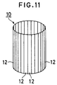
- Fig. 11 shows the second embodiment of a space light modulating apparatus of the invention and is characterized in that the same space light modulating units 12 as the space light modulating units 12-1 to 12-7 shown in Fig. 1 are arranged in a perfect arc shape along the cylindrical surface.
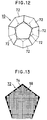
- Fig. 12 shows the third embodiment of the invention and is characterized in that the display section 10 of a regular dodecahedron is formed by arranging space light modulating units 72 each having a regular pentagon.
- Fig. 13 shows one of the space light modulating units 72 of the regular pentagon which are used in the space light modulating apparatus that is constructed by the regular dodecahedron of Fig. 12.
- a liquid crystal display units shown in Figs. 7 and 8 are used and the liquid crystal cells 58 are arranged in a matrix form in regions other than a non-display region 74 shown by a black area.
- Fig. 14 shows a modification of Fig. 12 and is characterized in that three space light modulating units 72 of the regular pentagon arranged on the lower side of the display section 10 which is constructed by the regular dodecahedron of Fig. 12 are removed, thereby forming a dome shape.
- Fig. 15 shows the fourth embodiment of a space light modulating apparatus of the invention and is characterized in that the display section 10 of a regular trisoctahedron is formed by arranging space light modulating units 76 of a regular triangle along a spherical surface.
- the space light modulating units 76 of a regular triangle which are used in the embodiment have an arrangement structure of the liquid crystal cells 58 shown in Fig. 16.
- Fig. 17 is characterized in that the five space light modulating units 76 of the regular triangle on the lower side with respect to the fourth embodiment of Fig. 15 are removed, thereby forming a dome shape.
- Fig. 18 shows the fifth embodiment of a space light modulating apparatus of the invention and is characterized in that the display section 10 as a polyhedron of the Fullerene type is formed by combining the space light modulating units 72 of the regular pentagon and space light modulating units 78 of a regular hexagon along a spherical surface.
- the space light modulating units 78 of the regular hexagon which are used in Fig. 18 have a matrix-like arrangement of the liquid crystal cells 58 shown in Fig. 19.
- Fig. 20 is characterized in that a dome shape is formed by removing the portion on the lower side of the display section 10 comprising polyhedrons of the Fullerene type of Fig. 18.
- Fig. 21 shows the fifth embodiment of a space light modulating apparatus of the invention and is characterized in that the display section 10 is formed by arranging circular space light modulating units 80 having a matrix arrangement of the liquid crystal sells 58 shown in Fig. 22 along a spherical surface.
- Fig. 23 is characterized in that a dome shape is formed by removing the lower half portion of Fig. 21.
- the spatial frequency can be lowered by reducing the diffraction angles in all of the directions including the horizontal and vertical direction.
- a size of the space light modulating apparatus in each of the foregoing embodiments is properly decided as necessary and is not limited.
- a stereoscopic display can be performed at a low spatial frequency. Even when a pixel density is small, a solid image can be displayed on a large screen. A clear solid image can be displayed because it is not so away from the visual point.
Abstract
Description
- The invention relates to a space light modulating apparatus and a stereoscopic display apparatus, for example for use in a rewritable hologram stereoscopic display.
- A stereoscopic display is a method of enabling a structure such as depth, thickness, or the like of a 3-dimensional object to be easily visually understood. Such a stereoscopic display is largely demanded in the display field of the structure designed by a CAD or the like or the display field of a medical image. The stereoscopic display has a feeling of a reality and is impressive as compared with the 2-dimensional display and is also used in the display for amusement in an amusement park, a movie, or the like.
- A conventional rewritable hologram stereoscopic display apparatus is realized by using, for example, an acoustic optical element (AOM) for generating a calculated 1-dimensional interference fringe, a rotary mirror, a galvano mirror, a reducing lens, and the like (refer to "Practical Holography VI, #1212-20", SPIE Proc., Vol. 1212, 1990). Since such an apparatus has mechanical movable portions, however, there is a drawback such that it is difficult to realize a large screen and to miniaturize the apparatus.
- On the other hand, in association with the recent improvement of the performance of the liquid crystal display apparatus, a space light modulating apparatus which can dynamically change a hologram has been examined. There has been proposed an apparatus in which a phase distribution of the hologram is displayed by using a liquid crystal display apparatus and a solid image is reconstructed by irradiating an illuminate light to the phase distribution (refer to JP-A-64-84933). According to such an apparatus, since the hologram is rewritten by an electrical control, the apparatus can be miniaturized by the installing technique of driving electronic circuits.
- In the display of the phase distribution of the hologram using such a conventional liquid crystal display apparatus, however, according to the present technique, a pixel density of the ordinary liquid crystal display apparatus is equal to a value on the order of about 10³ per line and is not so fine, so that it is difficult to express an interference fringe of a high spatial frequency, namely, a phase distribution. That is, in order to display a solid image in front of the space light modulating apparatus or in a wide visual field, a space light modulating element which can display an interference fringe at a high spatial frequency is needed. According to the pixel density of the present liquid crystal display apparatus, however, there is a problem such that an interference fringe at a high spatial frequency cannot be produced.
- Various aspects of the invention are exemplified by the attached claims.
- It will be apparent that embodiments of the invention may provide a space light modulating apparatus which can properly display a solid image by a phase distribution at a low spatial frequency. In particular, an interference fringe as a phase distribution may be produced on a space light modulating apparatus in which the phase distribution display surface has an arc-like curved surface and a solid image is displayed at a position near the center of the arc. A solid image, thus, may be stereoscopically displayed at a low spatial frequency. The phase display surface forming the curved surface may be an imaginary surface and a plurality of flat space light modulating units each having a predetermined area are arranged along the imaginary surface, thereby forming a phase distribution display surface. That is, the space light modulating apparatus may have a plurality of flat space light modulating units each having a predetermined area for performing a wave front conversion while setting the position of a cross point of the normal line from the virtual display surface into a producing position of a solid image are arranged along the virtual display surface having a non-plane shape, for example, a cylindrical surface or a spherical surface to display the phase distribution.
- Embodiments of the invention may provide a stereoscopic display apparatus in which a phase distribution of a virtual object is calculated and a space light modulating apparatus is driven and a solid image is displayed is provided. The stereoscopic display apparatus may comprise: phase distribution calculating means for calculating a phase distribution (interference fringe) on the basis of 3-dimensional image information to be displayed; and display driving means for displaying the phase distribution obtained by the phase distribution calculating means to each of flat space light modulating units of the space light modulating apparatus and for allowing a solid image to be displayed by the wave front conversion by irradiation of a reference light.
- Space light modulating apparatus and stereoscopic display apparatus even in case of producing the same solid image, may express the solid image by a diffraction of a low angle by producing an interference fringe to the space light modulating apparatus of a curved surface rather than producing an interference fringe to the space light modulating apparatus of a flat surface. Since the diffraction angle is low, the spatial frequency of the interference fringe can be also set to a low frequency. Particularly, by setting a position near the cross point of the normal line from the curved surface of the space light modulating apparatus (near the center of the spherical surface or arc) into a producing position of the solid image, a stereoscopic display can be performed by the diffraction of the lowest angle. On the other hand, since it is difficult in manufacturing to actually form micro pixels onto the space light modulating apparatus having a curved surface, a plurality of flat space light modulating units each having a small area are arranged. In this case, although the display surface of the phase distribution is locally flat, the stereoscopic display can be executed at a spatial frequency that is lower than that in the case where the whole display surface is formed by a flat surface.
- Such a space light modulating apparatus and a stereoscopic display apparatus can be designed to display a solid image at a practical pixel density.
- For a better understanding of the invention and to show how the same may be carried into effect, reference will now be made, by way of example, to the accompanying drawings, wherein:
- Fig. 1 is an explanatory diagram showing the first embodiment of the invention;
- Fig. 2A is an explanatory diagram showing a conventional display of a real image;
- Fig. 2B is an explanatory diagram showing a display of a real image.
- Fig. 3A is an explanatory diagram showing a conventional display of a virtual image;
- Fig. 3B is an explanatory diagram showing a display of a virtual image.
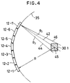
- Fig. 4 is a plan view showing a display of a solid image by a display section in Fig.1;
- Fig. 5 is an explanatory diagram showing an embodiment of a display unit which is used in the embodiment of Fig.1;
- Fig. 6 is an explanatory diagram showing another embodiment of the display unit which is used in the embodiment of Fig.1;
- Fig. 7 is a cross sectional view of a liquid crystal display which is used as a display unit;
- Fig. 8 is an explanatory diagram showing a phase modulation for a reproduction light with respect to three of liquid crystal cells in Fig. 7;
- Fig. 9 is a cross sectional view showing a structure of an illuminating unit in Fig.1;
- Fig. 10 is an explanatory diagram showing a principle of the phase distribution calculation;
- Fig. 11 is an explanatory diagram showing the second embodiment of a space light modulating apparatus according to the invention;
- Fig. 12 is an explanatory diagram showing the third embodiment of a space light modulating apparatus which is constructed by a regular dodecahedron;
- Fig. 13 is an explanatory diagram showing a space light modulating unit of a regular pentagon which is used in the embodiment of Fig. 12;
- Fig. 14 is a constructional diagram showing a modification of the third embodiment in which a part of Fig. 12 is omitted;
- Fig. 15 is an explanatory diagram showing the fourth embodiment of a space light modulating apparatus which is constructed by a regular trisoctahedron;
- Fig. 16 is an explanatory diagram of a space light modulating unit of a regular triangle which is used in the embodiment of Fig. 15;
- Fig. 17 is an explanatory diagram showing a modification of the fourth embodiment in which a part of Fig. 15 is omitted;
- Fig. 18 is an explanatory diagram showing the fifth embodiment of a space light modulating apparatus which is constructed by a polyhedron comprising a combination of a regular pentagon and a regular hexagon;
- Fig. 19 is an explanatory diagram of a space light modulating unit of a regular hexagon which is used in the embodiment of Fig. 18;
- Fig. 20 is an explanatory diagram showing a modification of the fifth embodiment in which a part of Fig. 18 is omitted;
- Fig. 21 is an explanatory diagram showing the fifth embodiment of a space light modulating apparatus which is constructed by polyhedrons arranged in a spherical shape;
- Fig. 22 is an explanatory diagram of a circular space light modulating unit which is used in the embodiment of Fig. 21;
- Fig. 23 is an explanatory diagram showing a modification of the sixth embodiment in which a part of Fig. 21 is omitted.
- Fig. 1 shows the first embodiment of the invention. A
display section 10 is constructed by coupling seven space light modulating units 12-1 to 12-7 byflexible coupling portions 18. By attaching thedisplay section 10 onto abase plate 15, the space light modulating units are arranged along a cylindrical surface having a predetermined radius. The space light modulating units 12-1 to 12-7 have a combination structure of liquid crystal display units 14-1 to 14-7 provided on the inside and illuminating units 16-1 to 16-7 provided on the outside, respectively. In each of the liquid crystal display units 14-1 to 14-7, a number of micro liquid crystal cells are arranged in a matrix form in order to display an interference fringe as a calculated phase distribution on the inside. Aconnector unit 20 is attached to the side surface of the space light modulating unit 12-1. Asignal line 25 from adisplay driving section 24 is connected to theconnector unit 20. A phasedistribution calculating section 22 is provided for thedisplay driving section 24. - The principle in which a proper solid image can be displayed at a low spatial frequency in the space light modulating apparatus of the invention will now be described. Fig. 2A is a diagram showing a conventional flat space
light modulating apparatus 26. Fig. 2B is a diagram showing an arc-shaped spacelight modulating apparatus 40. In the flat spacelight modulating apparatus 26 of Fig. 2A, in case of displaying a real image 30-1 when it is seen from avisual point 38 for the irradiation of areference light 28, it is necessary to perform a diffraction at a large angle ϑ₁ which is decided by aline 34 on the lower side of the real image 30-1 for anormal line 32. A phase distribution at a high spatial frequency must be displayed. On the other hand, as shown in Fig. 2B, in case of the arc-shaped spacelight modulating apparatus 40, by constructing such that anormal line 42 of the spacelight modulating apparatus 40 passes through acenter 45 of the real image 30-1 to be displayed, a diffraction angle for thereference light 28 in case of displaying the real image 30-1 at the same position when it is seen from thevisual point 38 can be set to a small angle ϑ₂ forlines normal line 42. Since the real image 30-1 can be displayed by the diffraction of such a small angle ϑ₂ as mentioned above, a spatial frequency of an interference fringe as a phase distribution which is produced on the arc surface of the spacelight modulating apparatus 40 can be set to a low frequency. This point also shall apply to the display of a virtual image shown in each of Figs. 3A and 3B. - On manufacturing of a liquid crystal, however, it is difficult to actually realize space
light modulating apparatuses
Therefore, as shown in Fig. 4, by virtually setting anarc 35 of a radius R in which thecenter 45 is set to the display position of the real image 30-1 and by arranging a plurality of space light modulating units 12-1 to 12-7 along avirtual arc 35, a space light modulating apparatus having an arc-shaped surface is equivalently realized. - Fig. 5 is a diagram showing liquid crystal display units which are used in the space light modulating units 12-1 to 12-7 in Fig. 1. A number of micro
liquid crystal cells 58 are arranged in a matrix form on the display surface of the liquidcrystal display unit 14. - Fig. 6 shows another embodiment of the liquid
crystal display unit 14 which is used in the embodiment of Fig. 1. The embodiment is characterized in that aliquid crystal segment 60 in which a predetermined number ofliquid crystal cells 58 are arranged in a matrix form is set to one unit and that a plurality of suchliquid crystal segments 60 are two-dimensionally arranged in a matrix form. By combining a plurality ofliquid crystal cells 58 everyliquid crystal segment 60 as mentioned above, the liquidcrystal display unit 14 can be easily manufactured as compared with the case where theliquid crystal cells 58 are arranged on the whole surface as shown in Fig. 5. - Fig. 7 shows a structure of the liquid crystal display unit. The liquid
crystal display unit 14 has a uniformtransparent electrode 144 subsequent to a glass substrate 140 on the incident surface side. Branched transparent electrodes 146-1 to 146-n constructing one display segment are formed subsequent to a glass substrate 142 on the outgoing side.Orientation films layers transparent electrodes 144 and 146-1 to 146-n. Aliquid crystal 160 is provided between theorientation films crystal display unit 14 is driven so that the voltage corresponding to the calculated phase information is applied to every liquid crystal cells which are decided by the divided electrodes 146-1 to 146-n. A refractive index of the liquid crystal cell for the transmitting direction of areproduction light 162 is changed in accordance with the applied voltage. - Fig. 8 shows a state of phase modulation with respect to three pixels of the liquid crystal display in Fig. 7 as an example. It is now assumed that reproduction lights 162-1 to 162-3 comprising, for instance, plane waves having the same phase entered from the left side into pixels 166-1,166-2, and 166-3 which had been driven into different phase states, namely, to different refractive indices. In this case, since the optical distances in the liquid crystal differ in dependence on the pixels 166-1 to 166-3, phase deviations occur in lights 164-1 to 164-3 upon outgoing. It is ideally demanded that an arbitrary phase within a range of 0 to 2π, namely, a range of a length corresponding to the wavelength as an optical distance can be expressed. Even when the phase is discretely expressed by multivalue levels, however, the phase distribution can be approximately expressed in a practical range. A depth of liquid crystal is decided so as to satisfy conditions such that the product Δn x d of the thickness d and a change Δn in maximum refractive index which can be changed by the applied voltage is equal to a wavelength λ of the reproduction light.
- Fig. 9 shows an embodiment of the illuminating units 16-1 to 16-2 provided on the back side of the space light modulating units 12-1 to 12-7 shown in Fig. 1. A
laser light source 66 is built in on the lower side of the illuminatingunit 16. It is desirable to use a small semiconductor laser as alaser light source 66. The semiconductor laser has a light emitting spectrum whose wavelength width is a few nm or less and can reconstruct a clear solid image. As a wavelength, an arbitrary wavelength can be used so long as it lies within a visible light range. It is necessary to consider a wavelength of light source which is used for reconstruction at the stage of calculating a phase distribution of a hologram. Specifically speaking, it is possible to use a semiconductor laser which emits the light of red whose wavelength is on the order of 600 nm, the light of green whose wavelength is on the order of 500 nm, or the light of blue whose wavelength is on the order to 400 nm. The light from thelaser light source 66 is converted into the parallel light by acollimating mirror 68 and is irradiated upward. Twelve half mirrors 70-1 to 70-12 are arranged in the vertical direction of the illuminatingunit 16 in the embodiment. The half mirrors 70-1 to 70-12 have transmission factors T₁ to T₁₂. Each half mirror reflects a part of the incident light. The reflected light enters the liquidcrystal display unit 14 as a reproduction light. A part of the incident light also enters the next half mirror. Now, assuming that light intensities of the reflected lights from the half mirrors 70-1 to 70-12 are set to P₁ to P₁₂, all of the light intensities P₁ to P₁₂ need to be equalized. For this purpose, the transmission factors T₁ to T₁₂ of the half mirrors 70-1 to 70-12 are made different so as to equalize all of the light intensities P₁ to P₁₂. In the case where a coefficient i indicative at the position of the half mirror 70-12 which is farthest from the light source is set to i = 12 and the coefficient i indicative of the half mirror 70-1 at the nearest position from the light source is set to i = 1, the transmission factors T₁ to T₁₂ can be obtained as

where, n denotes the number of half mirrors and is set to n = 12 in the embodiment. That is, it is sufficient that the transmission factors T₁, T₂, ···, T₁₁, and T₁₂ of the half mirrors 70-1 to 70-12 are set to 11/12, 10/11, ···, 1/2, and 0, respectively. - The processing operation of the phase
distribution calculating section 22 shown in Fig. 1 will now be described. First, the principle of the hologram will be explained. A hologram is obtained as follows. One laser beam is divided into two beams. One laser beam is irradiated to an object, so that a laser beam (object light) is scattered by the object. A hologram is obtained by an interference of two light fluxes of the laser beam (object light) and another laser beam (reference light). Now, assuming that a wave front of the reference light is set to R exp(jφr) and a wave front of the object light is set to O exp(jφo), an exposure intensity IH of the hologram is

In case of developing the hologram, changes in amplitude and phase which are proportional to the exposure intensity IH of the equation (1) occur in the hologram. To electrically form a hologram, it is sufficient to use a space light modulating apparatus such as a liquid crystal device or the like which can change an amplitude or phase of the light. By inputting the same wave front as the reference light to the hologram formed as mentioned above, a hologram can be reconstructed. In the exposure intensity IH in the equation (1), only the third term of the right side contributes to the reconstruction of the object light. Therefore, when considering the third term of the right side, a transmission light T from the hologram is
where, the first term of the right side in the equation (2) indicates that the wave front from the object was reproduced. The second term of the right side indicates a conjugate wave of the object light. From the above description of the principle, it will be understood that in order to obtain a phase distribution of the hologram, it is sufficient to calculate only the third term of the right side in the equation (1). - Fig. 10 shows the principle by which a hologram is formed. When regarding the reference light as a plane wave, a light intensity R can be ignored because an intensity of plane wave is not changed depending on the position. When the plane wave enters perpendicularly to the hologram surface, it is also possible to set the phase φr = 0. An
object 62 to be displayed here is positioned so that an axial center line of a virtual cylindrical surface passes through, for example, the center of gravity. The coordinate system of a target space is set so that a proper reference position is set to an origin. Now, assuming that a luminance (scattering degree) at acertain sampling point 64 having the coordinates (Xi, Yi, Zi) of theobject 62 is set to Ii, the exposure intensity IH of one liquid crystal cell of ahologram display surface 100 on which thedisplay units 12 are arranged is
where, k indicates the number of waves of the laser beam

In case of Fig. 10, since the light from theobject 62 reaches the whole area of thehologram display surface 100, the calculations of the equations (3) and (4) are executed with respect to the whole area of thehologram display surface 100. - Referring again to Fig. 1, in the first embodiment of the invention described above, a position on the center axis of the space light modulating units 12-1 to 12-7 arranged along the cylindrical surface is set to a display center position of the solid image and, as shown in Fig. 10, a phase distribution which is expressed by each liquid crystal cell is calculated by the phase
distribution calculating section 22 on a unit basis of each space light modulating unit 12-1. On the basis of the result of the calculation of the phase distribution, the space light modulating units 12-1 to 12-7 are driven by thedisplay driving section 24 and the display driving according to the phase distribution is executed to each of the liquid crystal cells of the liquid crystal display units 14-1 to 14-7. At the same time, by irradiating reference lights as parallel lights by the illuminating units 16-1 to 16-7 from the back surface side as shown in Fig. 9, a solid image as a real image can be displayed in thedisplay section 10. In this instance, the space light modulating units 12-1 to 12-7 are arranged along the arc in the horizontal direction and are flat in the vertical direction, so that the spatial frequency in the horizontal direction can be lowered. - Although the embodiment of Fig. 1 has been described with respect to a display format of the real image 30-1 shown in Fig. 2B as an example, a display format of a virtual image as shown in Fig. 3B can be also used. Although Fig. 1 shows a state in which the space light modulating units 12-1 to 12-7 are arranged in an arc shape in the horizontal direction, by falling down the
display section 10 as a whole, the space light modulating units 12-1 to 12-7 can be arranged along the cylindrical surface in the vertical direction. - Fig. 11 shows the second embodiment of a space light modulating apparatus of the invention and is characterized in that the same space
light modulating units 12 as the space light modulating units 12-1 to 12-7 shown in Fig. 1 are arranged in a perfect arc shape along the cylindrical surface. - Fig. 12 shows the third embodiment of the invention and is characterized in that the
display section 10 of a regular dodecahedron is formed by arranging spacelight modulating units 72 each having a regular pentagon. Fig. 13 shows one of the spacelight modulating units 72 of the regular pentagon which are used in the space light modulating apparatus that is constructed by the regular dodecahedron of Fig. 12. A liquid crystal display units shown in Figs. 7 and 8 are used and theliquid crystal cells 58 are arranged in a matrix form in regions other than anon-display region 74 shown by a black area. - Fig. 14 shows a modification of Fig. 12 and is characterized in that three space
light modulating units 72 of the regular pentagon arranged on the lower side of thedisplay section 10 which is constructed by the regular dodecahedron of Fig. 12 are removed, thereby forming a dome shape. - Fig. 15 shows the fourth embodiment of a space light modulating apparatus of the invention and is characterized in that the
display section 10 of a regular trisoctahedron is formed by arranging spacelight modulating units 76 of a regular triangle along a spherical surface. The spacelight modulating units 76 of a regular triangle which are used in the embodiment have an arrangement structure of theliquid crystal cells 58 shown in Fig. 16. - Fig. 17 is characterized in that the five space
light modulating units 76 of the regular triangle on the lower side with respect to the fourth embodiment of Fig. 15 are removed, thereby forming a dome shape. - Fig. 18 shows the fifth embodiment of a space light modulating apparatus of the invention and is characterized in that the
display section 10 as a polyhedron of the Fullerene type is formed by combining the spacelight modulating units 72 of the regular pentagon and spacelight modulating units 78 of a regular hexagon along a spherical surface. The spacelight modulating units 78 of the regular hexagon which are used in Fig. 18 have a matrix-like arrangement of theliquid crystal cells 58 shown in Fig. 19. Fig. 20 is characterized in that a dome shape is formed by removing the portion on the lower side of thedisplay section 10 comprising polyhedrons of the Fullerene type of Fig. 18. - Fig. 21 shows the fifth embodiment of a space light modulating apparatus of the invention and is characterized in that the
display section 10 is formed by arranging circular spacelight modulating units 80 having a matrix arrangement of the liquid crystal sells 58 shown in Fig. 22 along a spherical surface. Fig. 23 is characterized in that a dome shape is formed by removing the lower half portion of Fig. 21. - In each of the embodiments of Fig. 12 to 23, since the space light modulating units each comprising a polyhedron or circular shape for the spherical surface are arranged by an inscription or circumscription, the spatial frequency can be lowered by reducing the diffraction angles in all of the directions including the horizontal and vertical direction. A size of the space light modulating apparatus in each of the foregoing embodiments is properly decided as necessary and is not limited.
- Therefore, as mentioned above, by arranging a plurality of flat space light modulating units along a non-flat shape, a stereoscopic display can be performed at a low spatial frequency. Even when a pixel density is small, a solid image can be displayed on a large screen. A clear solid image can be displayed because it is not so away from the visual point.
Claims (20)
- A space light modulating apparatus for displaying a 3-dimensional image at a display location (45), the apparatus comprising a plurality of substantially flat space light modulating units (12-1 to 12-7) for executing a wave front conversion, the units being arranged about an imaginary surface so that each of the modulating units has the normal to its surface passing through the display location (45).
- A space light modulating apparatus, wherein a plurality of flat space light modulating units, having a predetermined area for executing a wave front conversion while setting a position near a position of a cross point of a normal line from a virtual display surface of a non-flat shape into a producing position of a solid image are arranged along said virtual display surface.
- An apparatus according to claim 1 or 2 wherein a plurality of flat space light modulating units are arranged so as to be inscribed in said virtual display surface.
- An apparatus according to claim 1 or 2 wherein a plurality of flat space light modulating units are arranged so as to be circumscribed on said virtual display surface.
- An apparatus according to any one of the preceding claims wherein a virtual display surface of the non-flat shape is a cylindrical surface and a plurality of flat space light modulating units are arranged along said virtual cylindrical surface.
- An apparatus according to claim 5, wherein a plurality of flat space light modulating units are arranged in a part of said virtual cylindrical surface.
- An apparatus according to claim 1, 3 or 4, wherein said virtual display surface of the non-flat shape is a spherical surface and a plurality of flat space light modulating units are arranged along said virtual spherical surface.
- An apparatus according to claim 7, wherein a plurality of flat space light modulating units are arranged in a part of said virtual spherical surface.
- An apparatus according to claim 7, wherein a plurality of flat space light modulating units are arranged along said virtual spherical surface, thereby forming display means of a polyhedron.
- An apparatus according to claim 7, 8 or 9, wherein said space light modulating unit is set into a regular polyhedron shape and a plurality of said space light modulating units are arranged along said virtual spherical surface, thereby forming display means of a regular polyhedron.
- An apparatus according claim 7, 8 or 9 wherein said space light modulating unit is set into one kind of circular shape and a plurality of said space light modulating units are arranged along said virtual spherical surface, thereby forming display means of a polyhedron.
- An apparatus according to any one of the preceding claims wherein said space light modulating unit comprises: a display unit to express a phase distribution; and an illuminating unit for irradiating a reference light to said display unit and for reconstructing a solid image at a position of a cross point of a normal line from said virtual display surface.
- An apparatus according to claim 12, wherein said display unit is constructed by two-dimensionally arranging micro pixel structures to express a phase distribution in a matrix form.
- An apparatus according to claim 12, wherein said display unit has an array such that the number of micro pixels to express a phase distribution partially changes every row or column.
- An apparatus according to claim 12, 13 or 14 wherein in said pixel structure, an amplitude, a phase, or a polarizing state of the light is changed.
- An apparatus according to any one of claims 12 to 15 wherein said display unit is a liquid crystal display apparatus in which micro liquid crystal cells are two-dimensionally arranged in a matrix form.
- An apparatus according to any one of claims 12 to 16 wherein said illuminating unit comprises: a light source to generate a reproduction light; converting means for converting a light from said light source into a collimating light; and light distributing means for distributing the collimated light from said converting means to said display units and for inputting as a reproduction light.
- An apparatus according to claim 17, wherein said light distributing means is constructed by arranging a plurality of half mirrors, and each of said half mirrors reflects a part of the incident light and irradiates the reproduction light to said display unit and also transmits a part of the incident light, thereby allowing the transmitted light to enter the half mirror at the next stage.
- An apparatus according to claim 18, wherein said plurality of half mirrors have different transmission factors so as to equalize intensities of all of the reflected lights.
- A stereoscopic display apparatus comprising a space light modulating means according to any one of the preceding claims comprising, phase distribution calculating means for calculating a phase distribution on the basis of 3-dimensional image information to be displayed, and display driving means for displaying the phase distribution obtained by said phase distribution calculating means to each of said flat space light modulating units of said space light modulating means, thereby allowing a solid image to be displayed by a wave front conversion by an irradiation of a reference light.
Applications Claiming Priority (3)
| Application Number | Priority Date | Filing Date | Title |
|---|---|---|---|
| JP4248990A JPH06102813A (en) | 1992-09-18 | 1992-09-18 | Spacial light modulator and stereoscopic display device |
| JP248990/92 | 1992-09-18 | ||
| JP24899092 | 1992-09-18 |
Publications (3)
| Publication Number | Publication Date |
|---|---|
| EP0588509A2 true EP0588509A2 (en) | 1994-03-23 |
| EP0588509A3 EP0588509A3 (en) | 1996-05-29 |
| EP0588509B1 EP0588509B1 (en) | 2000-03-29 |
Family
ID=17186385
Family Applications (1)
| Application Number | Title | Priority Date | Filing Date |
|---|---|---|---|
| EP93306623A Expired - Lifetime EP0588509B1 (en) | 1992-09-18 | 1993-08-20 | Stereoscopic display apparatus |
Country Status (5)
| Country | Link |
|---|---|
| US (1) | US5594559A (en) |
| EP (1) | EP0588509B1 (en) |
| JP (1) | JPH06102813A (en) |
| CA (1) | CA2105118C (en) |
| DE (1) | DE69328223T2 (en) |
Cited By (6)
| Publication number | Priority date | Publication date | Assignee | Title |
|---|---|---|---|---|
| WO1996009864A1 (en) * | 1994-09-27 | 1996-04-04 | Oellers E Hans | Stage |
| EP1220189A2 (en) * | 2000-12-26 | 2002-07-03 | Ngk Insulators, Ltd. | Display apparatus |
| EP1331495A2 (en) | 2002-01-23 | 2003-07-30 | Omron Corporation | Surface light source device, diffusion plate and liquid crystal display device |
| EP1528442A1 (en) * | 2002-08-05 | 2005-05-04 | Pioneer Corporation | Spatial optical modulator |
| EP1650729A2 (en) * | 2004-10-07 | 2006-04-26 | Barco, naamloze vennootschap. | Improved display and corresponding support, emissive lighting display modules and packaging for such display modules |
| CN113903254A (en) * | 2020-10-12 | 2022-01-07 | 友达光电股份有限公司 | Display element and display device |
Families Citing this family (13)
| Publication number | Priority date | Publication date | Assignee | Title |
|---|---|---|---|---|
| US6195184B1 (en) | 1999-06-19 | 2001-02-27 | The United States Of America As Represented By The Administrator Of The National Aeronautics And Space Administration | High-resolution large-field-of-view three-dimensional hologram display system and method thereof |
| US10083542B1 (en) * | 1999-10-21 | 2018-09-25 | International Business Machines Corporation | Method and system to compare and search polyhedral shape |
| JP3513562B2 (en) * | 2000-04-20 | 2004-03-31 | インターナショナル・ビジネス・マシーンズ・コーポレーション | Shape analysis system, three-dimensional shape model difference detection system, similar shape search system, shape analysis method, and storage medium |
| GB2379351A (en) * | 2001-09-04 | 2003-03-05 | Holographic Imaging Llc | Illuminating a computer generated hologram |
| US6927886B2 (en) * | 2002-08-02 | 2005-08-09 | Massachusetts Institute Of Technology | Reconfigurable image surface holograms |
| KR101840405B1 (en) | 2008-07-10 | 2018-03-20 | 리얼 뷰 이미징 리미티드 | Broad viewing angle displays and user interfaces |
| CN102013222A (en) * | 2010-10-29 | 2011-04-13 | 鸿富锦精密工业(深圳)有限公司 | Spherical display screen |
| WO2012095703A1 (en) * | 2011-01-14 | 2012-07-19 | Onural, Levent | An apparatus and methods for holographic display |
| KR102250189B1 (en) * | 2014-07-29 | 2021-05-10 | 삼성전자주식회사 | Apparatus and method for holographic generation |
| WO2016076749A1 (en) * | 2014-11-14 | 2016-05-19 | Михаил Алексеевич ФИЛИМОНОВ | Device for visually displaying information |
| CN206833886U (en) * | 2017-04-11 | 2018-01-02 | 河北思安科技有限公司 | Intelligent laser projects multimedia advertising platform |
| KR20210034585A (en) * | 2018-07-25 | 2021-03-30 | 라이트 필드 랩 인코포레이티드 | Amusement park equipment based on light field display system |
| CN110442006B (en) * | 2019-06-28 | 2021-08-27 | 京东方科技集团股份有限公司 | Hologram reproduction device, hologram reproduction system, and hologram display system |
Citations (5)
| Publication number | Priority date | Publication date | Assignee | Title |
|---|---|---|---|---|
| JPS5786815A (en) * | 1980-11-19 | 1982-05-31 | Yokogawa Hokushin Electric Corp | Photoscanner |
| DE3140418A1 (en) * | 1981-10-12 | 1983-05-05 | Stadelmayr, Hans-Günther, 8000 München | Image and three-dimensional image (hologram) production transmission and reproduction system for large sizes (extensity) with, at the same time, high resolution (intensity) |
| GB2209422A (en) * | 1987-09-03 | 1989-05-10 | Emi Plc Thorn | Displays |
| US5111313A (en) * | 1989-08-10 | 1992-05-05 | Shires Mark R | Real-time electronically modulated cylindrical holographic autostereoscope |
| US5119214A (en) * | 1990-03-26 | 1992-06-02 | Matsushita Electric Industrial Co., Ltd. | Method for forming a computer generated hologram |
Family Cites Families (6)
| Publication number | Priority date | Publication date | Assignee | Title |
|---|---|---|---|---|
| US3601466A (en) * | 1968-06-21 | 1971-08-24 | Nippon Kogaku Kk | Method for detecting an aberration-compensated image |
| US3591252A (en) * | 1968-10-21 | 1971-07-06 | Texas Instruments Inc | Large array synthesizing |
| DE2229381A1 (en) * | 1972-06-16 | 1974-01-03 | Agfa Gevaert Ag | METHOD AND DEVICE FOR RECORDING AN OBJECT WAVE FIELD STORED IN A HOLOGRAM |
| US4863225A (en) * | 1986-03-26 | 1989-09-05 | Gec Avionics Limited | Reflection holograms formed by scanning |
| FR2633069B1 (en) * | 1988-06-20 | 1993-12-31 | Garcon Thierry | METHOD FOR PRODUCING A LARGE FIELD OF VIEW TRANSFER HOLOGRAM ON ITS ACTUAL ORTHOSCOPIC IMAGING AND HOLOGRAM THUS OBTAINED |
| US5198914A (en) * | 1991-11-26 | 1993-03-30 | Hughes Aircraft Company | Automatic constant wavelength holographic exposure system |
-
1992
- 1992-09-18 JP JP4248990A patent/JPH06102813A/en active Pending
-
1993
- 1993-08-20 EP EP93306623A patent/EP0588509B1/en not_active Expired - Lifetime
- 1993-08-20 DE DE69328223T patent/DE69328223T2/en not_active Expired - Fee Related
- 1993-08-30 CA CA002105118A patent/CA2105118C/en not_active Expired - Fee Related
-
1996
- 1996-04-10 US US08/632,346 patent/US5594559A/en not_active Expired - Lifetime
Patent Citations (5)
| Publication number | Priority date | Publication date | Assignee | Title |
|---|---|---|---|---|
| JPS5786815A (en) * | 1980-11-19 | 1982-05-31 | Yokogawa Hokushin Electric Corp | Photoscanner |
| DE3140418A1 (en) * | 1981-10-12 | 1983-05-05 | Stadelmayr, Hans-Günther, 8000 München | Image and three-dimensional image (hologram) production transmission and reproduction system for large sizes (extensity) with, at the same time, high resolution (intensity) |
| GB2209422A (en) * | 1987-09-03 | 1989-05-10 | Emi Plc Thorn | Displays |
| US5111313A (en) * | 1989-08-10 | 1992-05-05 | Shires Mark R | Real-time electronically modulated cylindrical holographic autostereoscope |
| US5119214A (en) * | 1990-03-26 | 1992-06-02 | Matsushita Electric Industrial Co., Ltd. | Method for forming a computer generated hologram |
Non-Patent Citations (2)
| Title |
|---|
| PATENT ABSTRACTS OF JAPAN vol. 006 no. 168 (P-139) ,2 September 1982 & JP-A-57 086815 (YOKOGAWA HOKUSHIN ELECTRIC CORP) 31 May 1982, * |
| PROGRESS IN HOLOGRAPHY, THE HAGUE, NETHERLANDS, 31 MARCH-2 APRIL 1987, vol. 812, ISSN 0277-786X, PROCEEDINGS OF THE SPIE - THE INTERNATIONAL SOCIETY FOR OPTICAL ENGINEERING, 1987, USA, pages 120-126, SCHULZE E 'Real-time holographic 3D imaging based on multiplexing techniques and optoelectronic holograms' * |
Cited By (10)
| Publication number | Priority date | Publication date | Assignee | Title |
|---|---|---|---|---|
| WO1996009864A1 (en) * | 1994-09-27 | 1996-04-04 | Oellers E Hans | Stage |
| EP1220189A2 (en) * | 2000-12-26 | 2002-07-03 | Ngk Insulators, Ltd. | Display apparatus |
| EP1220189A3 (en) * | 2000-12-26 | 2004-07-14 | Ngk Insulators, Ltd. | Display apparatus |
| EP1331495A2 (en) | 2002-01-23 | 2003-07-30 | Omron Corporation | Surface light source device, diffusion plate and liquid crystal display device |
| EP1528442A1 (en) * | 2002-08-05 | 2005-05-04 | Pioneer Corporation | Spatial optical modulator |
| EP1528442A4 (en) * | 2002-08-05 | 2008-04-02 | Pioneer Corp | Spatial optical modulator |
| EP1650729A2 (en) * | 2004-10-07 | 2006-04-26 | Barco, naamloze vennootschap. | Improved display and corresponding support, emissive lighting display modules and packaging for such display modules |
| EP1650729A3 (en) * | 2004-10-07 | 2007-11-28 | Barco, naamloze vennootschap. | Improved display and corresponding support, emissive lighting display modules and packaging for such display modules |
| CN113903254A (en) * | 2020-10-12 | 2022-01-07 | 友达光电股份有限公司 | Display element and display device |
| CN113903254B (en) * | 2020-10-12 | 2023-11-14 | 友达光电股份有限公司 | Display element and display device |
Also Published As
| Publication number | Publication date |
|---|---|
| JPH06102813A (en) | 1994-04-15 |
| DE69328223T2 (en) | 2000-09-07 |
| US5594559A (en) | 1997-01-14 |
| EP0588509B1 (en) | 2000-03-29 |
| CA2105118C (en) | 1999-01-05 |
| EP0588509A3 (en) | 1996-05-29 |
| DE69328223D1 (en) | 2000-05-04 |
| CA2105118A1 (en) | 1994-03-19 |
Similar Documents
| Publication | Publication Date | Title |
|---|---|---|
| EP0588509A2 (en) | Stereoscopic display apparatus | |
| US7414769B2 (en) | Reconfigurable spatial light modulators | |
| EP0589558B1 (en) | Stereoscopic display method and display apparatus | |
| US6473209B1 (en) | Apparatus for producing a three-dimensional image | |
| Yaraş et al. | State of the art in holographic displays: a survey | |
| EP0590913B1 (en) | Stereoscopic display method and apparatus | |
| KR101427057B1 (en) | A method of computing a hologram | |
| CN108803295B (en) | Method for manufacturing large-field-of-view hologram, display system and dot matrix light source | |
| US20050122549A1 (en) | Computer assisted hologram forming method and apparatus | |
| BRPI0612417A2 (en) | device for reconstructing three-dimensional scenes with video holograms | |
| JP2009533721A (en) | System and method for real 3D display of angular slices | |
| WO2005099386A2 (en) | Holographic projector | |
| JP2005506555A (en) | 3D display system | |
| JP2010507826A (en) | Holographic display device including magneto-optical spatial light modulator | |
| CN106647214A (en) | Addressing method of spatial light modulator, holographic display device and control method of holographic display device | |
| JPH11513814A (en) | Holographic high-contrast viewing screen built into the liquid crystal display | |
| US20140176671A1 (en) | Apparatus for displaying a hologram | |
| Toda et al. | Three-dimensional (3D) video system using grating image | |
| JP3338479B2 (en) | Hologram creation and stereoscopic display method and stereoscopic display device | |
| JPH1068906A (en) | Holographic display device | |
| KR100466622B1 (en) | Apparatus and method for manufacturing holographic diffraction field element, 3D holographic display apparatus and method using it | |
| US5594564A (en) | Space light modulating apparatus having a length to width ratio of 30:1 and staggered drivers | |
| EP3129836A1 (en) | Wide viewing angle holographic video camera and display using a phase plate | |
| JP4739304B2 (en) | Light wavefront display device and light wavefront display method | |
| JPH06102812A (en) | Spacial light modulator and stereoscopic display device |
Legal Events
| Date | Code | Title | Description |
|---|---|---|---|
| PUAI | Public reference made under article 153(3) epc to a published international application that has entered the european phase |
Free format text: ORIGINAL CODE: 0009012 |
|
| AK | Designated contracting states |
Kind code of ref document: A2 Designated state(s): DE FR GB |
|
| PUAL | Search report despatched |
Free format text: ORIGINAL CODE: 0009013 |
|
| AK | Designated contracting states |
Kind code of ref document: A3 Designated state(s): DE FR GB |
|
| 17P | Request for examination filed |
Effective date: 19961121 |
|
| 17Q | First examination report despatched |
Effective date: 19970103 |
|
| GRAG | Despatch of communication of intention to grant |
Free format text: ORIGINAL CODE: EPIDOS AGRA |
|
| GRAG | Despatch of communication of intention to grant |
Free format text: ORIGINAL CODE: EPIDOS AGRA |
|
| GRAH | Despatch of communication of intention to grant a patent |
Free format text: ORIGINAL CODE: EPIDOS IGRA |
|
| GRAH | Despatch of communication of intention to grant a patent |
Free format text: ORIGINAL CODE: EPIDOS IGRA |
|
| GRAA | (expected) grant |
Free format text: ORIGINAL CODE: 0009210 |
|
| AK | Designated contracting states |
Kind code of ref document: B1 Designated state(s): DE FR GB |
|
| REF | Corresponds to: |
Ref document number: 69328223 Country of ref document: DE Date of ref document: 20000504 |
|
| ET | Fr: translation filed | ||
| PLBE | No opposition filed within time limit |
Free format text: ORIGINAL CODE: 0009261 |
|
| STAA | Information on the status of an ep patent application or granted ep patent |
Free format text: STATUS: NO OPPOSITION FILED WITHIN TIME LIMIT |
|
| 26N | No opposition filed | ||
| REG | Reference to a national code |
Ref country code: GB Ref legal event code: IF02 |
|
| PGFP | Annual fee paid to national office [announced via postgrant information from national office to epo] |
Ref country code: FR Payment date: 20060808 Year of fee payment: 14 |
|
| PGFP | Annual fee paid to national office [announced via postgrant information from national office to epo] |
Ref country code: GB Payment date: 20060816 Year of fee payment: 14 |
|
| PGFP | Annual fee paid to national office [announced via postgrant information from national office to epo] |
Ref country code: DE Payment date: 20060817 Year of fee payment: 14 |
|
| GBPC | Gb: european patent ceased through non-payment of renewal fee |
Effective date: 20070820 |
|
| REG | Reference to a national code |
Ref country code: FR Ref legal event code: ST Effective date: 20080430 |
|
| PG25 | Lapsed in a contracting state [announced via postgrant information from national office to epo] |
Ref country code: DE Free format text: LAPSE BECAUSE OF NON-PAYMENT OF DUE FEES Effective date: 20080301 |
|
| PG25 | Lapsed in a contracting state [announced via postgrant information from national office to epo] |
Ref country code: FR Free format text: LAPSE BECAUSE OF NON-PAYMENT OF DUE FEES Effective date: 20070831 |
|
| PG25 | Lapsed in a contracting state [announced via postgrant information from national office to epo] |
Ref country code: GB Free format text: LAPSE BECAUSE OF NON-PAYMENT OF DUE FEES Effective date: 20070820 |