Field of the Invention
This invention relates to multilayer films,
and, more particularly, to tear resistant multilayer
films based on sebacic acid copolyesters.
Description of the Related Art
Traditionally, "tear resistance" has
described the ability of a film to resist continuing
to tear once a tear has been started. Trash and
grocery bags, often based on polyolefins such as
polyethylene, are examples of films that are
conventionally considered to be tear resistant.
These films have considerable stretch which enables
them to resist advancing an already formed tear. By
"stretch" it is meant that the films have a low
tensile modulus and are not dimensionally stable.
Also known are films which are relatively
stiff. In this regard, "stiff" refers to films which
cannot be stretched significantly without breaking;
that is, films which are dimensionally stable, creep-resistant
(stretch resistant), and of high modulus.
Examples of stiff, dimensionally stable, high modulus
materials are certain packaging films such as
cellophane, polyesters and biaxially oriented
polypropylene. However, these films have low tear
resistance. That is, once a tear has been started,
the film continues to tear quite easily.
resistance. That is, once a tear has been started,
the film continues to tear quite easily.
There are numerous applications where
stiff, tear resistant films would be desirable. For
example, films which provide sign faces and building
awnings must be tear resistant to have a useful life.
On the other hand, these films must also be
relatively stiff so that they will not billow in the
wind or sag with age.
Backings for abrasive sanding belts
experience harsh operating conditions and must resist
tearing. However, sanding belts which stretch are
undesirable because they may not fit securely on the
sander and may work free under normal use.
Angioplasty balloons for expanding blood
vessels during surgery require stiff, tear resistant
films. The balloons cannot readily shatter (i.e.,
tear) during use. The balloons must also inflate to
a controlled size and should not stretch to a larger
size.
For certain tapes, stiff, tear resistant
backings would be desirable. Such backings would not
readily continue to tear if inadvertently nicked or
cut when dispensed. At the same time, the backings
would be stretch resistant which could enhance the
stability of articles taped therewith.
Films for shatterproofing windows need to
be tear resistant. However, the performance of such
films would be enhanced if the films were also stiff
and tear resistant as the combination of these
properties would help the film to absorb energy in
the event of a window shattering impact.
Numerous packaging films are disclosed in
the prior art. U.S. Patent No. 3,188,265, "Packaging
Films" issued June 8, 1965 to R. Charbonneau, et al.
discloses a heat-sealable film comprising
polyethylene extruded onto a web of oriented
polyethylene terephthalate. U.S. Patent No.
4,705,707 "Polyethylene/Polyester Non Oriented Heat
Sealable, Moisture Barrier Film and Bag," issued
November 10, 1987 to J. Winter discloses a moisture
barrier film useful in microwaveable food pouches.
The film comprises three and five layer nonoriented
structures of polyethylenes and polyesters or
copolyesters.
U.S. Patent No. 4,965,108 "Low Temperature
Impact and Puncture Resistant Thermoplastic Films and
Bags Therefrom," issued October 23, 1990 to E. Biel
et al. discloses multilayer film and bag structures
comprising a polypropylene copolymer inner layer, an
outer layer (e.g., a polyester or a polyamide), and a
polypropylene based bonding resin therebetween.
U.S. Patent No. 4,636,442 "Laminated
Structures of Polyethylene Terephthalate and
Elastomeric Copolyesterethers," issued January 13,
1987, to R. Beavers et al. discloses multilayer films
reportedly having improved flex-crack resistance.
The films are based on polyethylene terephthalate and
elastomeric copolyesterethers. Biaxially oriented
three and five layer films in which the amount of
copolyesterether is from about 5 to about 75 weight %
(preferably 10 to 60 weight %) are disclosed.
U.S. Patent No. 4,939,009 "Multilayer
Sheets Having Excellent Adhesion," issued July 3,
1990, also to R. Beavers et al., discloses three and
five layer films based on polyolefins and
copolyesterethers with tie layers therebetween.
U.S. Patent No. 4,729,927 "Polyester
Packaging Material," issued March 8, 1988, to M.
Hirose et al. discloses a packaging material
comprising polyethylene terephthalate and a second
material based on polyethylene isophthalate
copolymerized with an aliphatic hydroxycarboxylic
acid having up to eight carbon atoms. Reportedly,
the number of layers is not particularly critical,
although films with up to five layers are said to be
preferred.
Japanese Kokai Patent No. 2-270553
"Multilayer Plastic Sheet with Gas Barrier Feature,"
published November 5, 1990 discloses multilayer films
based on layers of saponified ethylene/vinyl acetate
copolymers, modified polyolefin adhesives, and
thermoplastic polyesters.
Impact resistant and/or shatterproof
security films for windows are also known. For
example, U.S. Patent No. 3,899,621 "Security Film for
Shatter-Proofing Windows," issued August 12, 1975 to
M. Willdorf discloses three and five layer films
comprising layers of polyesters and polyurethanes.
Preferably, the polyester layers range in thickness
from 0.5 to 5 mils and the polyurethane layers range
in thickness from 0.2 to 0.4 mil. U.S. Patent No.
3,891,486 "Process for Producing Solar Control
Window," issued June 24, 1975, also to M. Willdorf,
discloses a solar control film comprising a pair of
polyester (e.g., polyethylene terephthalate) layers
each from 0.25 to 1 mil thick with a vapor-deposited
aluminum coating and an adhesive therebetween.
U.S. Patent No. 4,945,002 "Impact-Resisting
Anti-Lacerative Window Units," issued July 31, 1990
to I. Tanuma et al. discloses a three layer film
comprising two exterior layers (e.g., an
ethylene/vinyl acetate copolymer, an ethylene/vinyl
acetate/triallyl isocyanurate terpolymer, a polybutyl
butyryl, a polyvinylformal, or a polyurethane), and
an intermediate layer (e.g. polyethylene
terephthalate, polyamides, polyester polyethers,
polysulfones or polyimides) therebetween. The film
is sandwiched between a pair of transparent glass or
plastic plates.
Various tapes are also known. For example,
U.S. Patent No. 4,091,150 "Coextruded Polyester
Splicing Tape," issued May 23, 1978 to G. Roelofs
discloses a multilayer tape comprising a support film
formed from a tough, flexible polyester (e.g.
polyethylene naphthalate or polyethylene
terephthalate) which is coextruded with an adhesion
promoting polyester. A thermoset adhesive is
adherently bonded to the adhesion promoting
polyester.
U.S. Patent No. 4,908,278 "Severable
Multilayer Thermoplastic Film," issued March 13, 1990
to Bland et al. discloses a multilayer film which may
be easily and precisely cut in a straight line. The
film comprises alternating layers of brittle and
ductile materials. Japanese Kokoku Patent
Publication No. 63-5394 "Laminate Film," published
October 26, 1988, discloses three and five layer tape
backing films comprising layers of different
polyesters. Reportedly, the films have good manual
tearing properties.
U.S. Patent No. 4,540,623 "Coextruded
Multi-layer Articles," issued September 10, 1985 to
J. Im et al. discloses an impact resistant multilayer
laminate comprising alternating layers (preferably at
least about 40 layers) of coextruded polymeric
thermoplastics wherein one of the materials contains
a carbonate polymer. Suggested uses include glazing
applications for windows and signs.
European Patent Application No. 0,426,636
"Iridescent Film with Thermoplastic Elastomeric
Components," published May 8, 1991 discloses a
transparent thermoplastic film of at least ten
layers. The adjacent layers differ in refractive
index and at least one of the layers is based on a
thermoplastic elastomer resin. The layers range in
thickness from 30 to 500 nanometers.
The article "Some Physical Properties of Multilayered Films"
by W.J. Schrenk and T. Alfrey Jr., Polymer Engineering and
Science, November, Vol.9, No.6, p. 393 - 399, 1969, discloses
multilayered films comprising layers of high and low modulus
materials.
The article "Advanced Polymers" by Eric Bauer, Scientific
American, October, 1986, pages 161, 164, discloses a sheet
of alternating layers of stiff and ductile materials.
SUMMARY OF THE INVENTION
In general, this invention relates to a
tear resistant film comprising at least three layers
situated one on the other in a parallel array. The
layers occur essentially randomly in the array and
are individually selected from a stiff polyester or
copolyester and a ductile sebacic acid based
copolyester.
The film comprises at least a layer of a stiff polyester or
copolyester and at least a layer of a ductile sebacic acid based
copolyester.
Preferably, the stiff polyester or
copolyester layers are oriented in at least one
direction and, more preferably, are biaxially
oriented.
By "tear resistant" it is broadly meant
that a film according to the invention demonstrates a
Graves area in one direction of the film which
exceeds the Graves area in the same direction for a
single layer film comprising only the stiff
polyester/copolyester of the multilayer film, the
single layer film being processed in the same manner
as and to substantially the same thickness as the
multilayer film. Preferably, multilayer films
according to the invention demonstrate a Graves area
in one direction of the film equal to at least about
40 + 0.4(x) kpsi% wherein x is the nominal thickness
of the film in microns. More specifically, Graves
area is obtained by mathematically integrating the
area beneath the curve in a graphical plot of the
stress (as measured in kpsi) experienced by the film
versus the strain (as measured by Graves elongation
in % which is defined more fully below) that the film
undergoes during a test in which a film sample
specifically shaped for the Graves area test is
clamped between opposed jaws that are moved apart at
a constant rate to concentrate the tearing stresses
in a small area. Thus, Graves area is a combined
measure of the film's tensile modulus (i.e., the
film's stiffness and dimensional stability) and the
ability of the film to resist advancing a tear.
Consequently, Graves area may be regarded as a
measure of the total energy required to cause the
film to fail; that is, the ability of the film to
absorb energy.
Moreover, preferred multilayer films
desirably exhibit a Graves elongation at break
(defined below) of at least 20%, more preferably at
least 40% during the Graves area test. In addition,
preferred multilayer tear resistant films according
to the invention demonstrate a tensile modulus (as
measured in a conventional tensile test) of at least
175 kpsi (1,208 MPa), more preferably at least 240
kpsi (1,656 MPa), and most preferably at least 450
kpsi (3,105 MPa) in at least one direction of the
film.
Both the thickness of the film and the
individual layers which comprise the film may vary
over wide limits. Films according to the invention
typically have a nominal thickness of from about 7 to
500 µm, more preferably from about 15 to 185 µm. The
individual layers of stiff polyester or
copolyester typically have an average nominal
thickness of at least about 0.5 µm, more preferably
from greater than 0.5 µm to 75 µm and, most
preferably, from about 1 to 25 µm. It is preferred
that the ductile sebacic acid based copolyester
layers be thinner than the stiff
polyester/copolyester layers. The ductile material
layers may range in average nominal thickness from
greater than about 0.01 µm to less than about 5 µm,
more preferably from about 0.2 to 3 µm.
Similarly, the exact order of the
individual layers is not critical. The total number
of layers may also vary substantially. Preferably,
the film comprises at least 3 layers, more preferably
from 5 to 35 layers, and most preferably 13 layers.
Stiff polyesters and copolyesters according
to the invention are typically high tensile modulus
materials, preferably materials having a tensile
modulus, at the temperature of interest, greater than
200 kpsi (1,380 MPa), and most preferably greater
than 400 kpsi (2,760 MPa). Particularly preferred
stiff polyesters and copolyesters for use in films
according to the invention comprise the reaction
product of a dicarboxylic acid component selected
from the group consisting of terephthalic acid,
naphthalene dicarboxylic acid and ester derivatives
thereof, and a diol component selected from the group
consisting of ethylene gylcol and 1,4-butanediol.
Additional stiff copolyesters based on these
materials may also be provided by copolymerizing
these ingredients with one or more other diacids
and/or one or more other diols.
Ductile sebacic acid based copolyesters
useful in the practice of the invention generally
have a tensile modulus of less than 200 kpsi (1,380
MPa) and a tensile elongation (as defined below), at
the temperature of interest, of greater than 50%,
preferably greater than 150%. A preferred ductile
copolyester comprises the reaction product of 20 to
80 (more preferably 70 to 50, and most preferably 60)
mole equivalents terephthalic acid (or an ester
derivative thereof), correspondingly, 80 to 20 (more
preferably 30 to 50, and most preferably 40) mole
equivalents sebacic acid (or an ester derivative
thereof), and 100 mole equivalents ethylene glycol.
The terephthalic acid may be replaced in whole or in
part by naphthalene dicarboxylic acid such as
dimethyl 2,6-napthalene dicarboxylic acid (or an
ester derivative thereof). In another preferred
embodiment, a portion of the sebacic acid is replaced
by an equivalent amount of cyclohexane dicarboxylic
acid (or an ester derivative thereof).
Surprisingly, beneficial improvements in
the tear resistance of films comprising alternating
layers of stiff polyesters/copolyesters and ductile
sebacic acid based copolyesters are realized when the
ductile material provides less than 5 weight % of the
film. Ductile material amounts of at least about 1
weight % (preferably at least about 2.6 weight %) up
to about 10 to 20 weight % of the film may be used.
Films according to the invention may
optionally include a layer of an intermediate
material disposed between otherwise adjacent layers
of the stiff and ductile polymers. Useful
intermediate materials may be selected from a wide
variety of polymers and, in some cases, may be
selected to enhance the adhesion between the
otherwise adjacent stiff and ductile layers. One or
more functional layers may also be applied to one or
both of the major surfaces of the film.
Multilayer films according to the invention
provide an improved combination of stiffness and tear
resistance especially when compared to films
comprising only a single layer of one of the
materials or single layer blends of both materials.
Films according to the invention are useful in a wide
variety of products, including, for example, sign
faces and backings for coated abrasive articles.
The multilayer tear resistant films of the
invention are particularly useful as security control
laminates for shatter-proofing glazing members
against impact or explosion. In one embodiment of
this application, the invention pertains to a
security control laminate comprising a first tear
resistant film having a first face and a first layer
of adhesive on the first face for bonding the
laminate to a glazing member. Typically, the
adhesive coated face of the tear resistant film is
temporarily disposed on a removable release liner
which is discarded during application of the laminate
to the glazing member. The security control laminate
may further comprise means for absorbing ultraviolet
radiation such as a coating layer interposed between
the first tear resistant film and the layer of
adhesive. Security control laminates according to
the invention may also comprise a dyed film (bonded
to the second face of the tear resistant film) and an
abrasion resistant coating on the otherwise exposed
surface of the dyed film.
In other embodiments, the security control
laminate may comprise a second tear resistant film
which is adhesively bonded to the first film. Such
constructions may also include ultraviolet radiation
absorbent and abrasion resistant coatings. Also
contemplated is the inclusion of a metalized layer
for imparting solar control properties to the
security control laminate. A metalized layer may
comprise an optically clear film having a layer of
aluminum, gold, silver, copper, nickel and the like
thereon. The security control laminate may be
applied to a single glazing member or positioned
between two glazing members. The glazing member(s)
can be mounted within a frame to which the security
control laminate may be optionally secured.
BRIEF DESCRIPTION OF THE DRAWINGS
The invention will be more fully understood
with reference to the following drawings in which
similar reference numerals designate like or
analogous components throughout and in which:
DETAILED DESCRIPTION OF THE PREFERRED EMBODIMENTS
The invention relates to tear resistant
multilayer films comprising interdigitated layers of
at least one ductile sebacic acid based copolyester
(sometimes referred to herein as the "ductile"
material), at least one stiff polyester or
copolyester (referred to herein sometimes as the
"stiff" material) and, optionally, at least one
intermediate material. The exact order of the
individual layers is not critical provided that at
least one layer of a stiff polyester/copolyester and
at least one layer of a ductile sebacic acid based
copolyester are present.
Examples of some film structures within the
scope of the invention include:
wherein S is the stiff polyester/copolyester, D is
the ductile sebacic acid based copolyester, I is the
optional intermediate material, x is a whole number
of at least 1 (preferably at least 2 and more
preferably about 6), and y is a whole number of at
least 1 (preferably at least 2 and more preferably
about 3). Other layer arrangements in which the
order is essentially random are also possible. The
two outer layers may be the same or may be different.
The individual stiff polyester/copolyester layers may
be comprised of the same or different materials so
long as the materials are stiff. Similarly, the
individual ductile sebacic acid based copolyester
layers may be comprised of the same or different
materials. Preferably, each stiff layer is provided
by the same material and each ductile layer is the
same so as to facilitate film production.
A film 10 according to the invention and
having the structure D(ISID)y, where y is 2 is shown
in FIG. 1. Film 10 includes 9 alternating layers of a
ductile sebacic acid based copolyester 11, an
intermediate material 12, and a stiff
polyester/copolyester 13. The two outer layers are
formed of ductile sebacic acid based copolyester 11.
However, the structure of FIG. 1 could be such that
either stiff polyester/copolyester 13 or intermediate
material 12 provides the outer layers. Preferably
the film comprises at least 3 layers, more preferably
from 5 to 35 layers, and most preferably about 13
layers, although as many layers as desired (e.g., 61
layers) may be employed.
The thickness of each layer and the total
thickness of the film may be varied over wide limits
within the scope of the invention. The practical
thickness of the film is limited only by the handling
characteristics desired. The lower useful practical
limit is that at which the film becomes too flimsy to
be readily handled or is no longer sufficiently tear
resistant while the upper useful limit is that at
which the film becomes overly rigid and too difficult
to process. Within these constraints, films
according to the invention typically have a nominal
thickness in the range of from about 7 to 500 microns
(i.e., micrometers) (µm) and, more preferably, from
about 15 to 185 µm.
The thickness of the individual layers may
also vary over a wide range, it being understood that
as the number of layers increases at a constant or
decreasing film thickness, the thickness of each
layer declines. The individual layers of stiff
polyester/copolyester typically have an average
nominal thickness of at least about 0.5 µm, more
preferably from 0.5 µm to 75 µm, and most preferably
from about 1 to 25 µm. Although the thickness of
each layer may be the same, it is preferred that the
ductile sebacic acid based copolyester layers be
thinner than the stiff polyester/copolyester layers.
The ductile sebacic acid based copolyester layers may
range in average nominal thickness from greater than
about 0.01 µm to less than about 5 µm, more
preferably, from about 0.2 to 3 µm. All film and
layer thickness stated herein are nominal thicknesses
which may be measured according to the procedure set
forth in ASTM Test Method D 1004.
Stiff polyesters/copolyesters useful in the
practice of the invention comprise the reaction
product of dicarboxylic acid (including ester
derivatives thereof) and diol components.
Preferably, the dicarboxylic acid component is either
terephthalic acid or naphthalene dicarboxylic acid
(such as dimethyl 2,6-napthalene dicarboxylic acid),
and the diol component is either ethylene glycol or
1,4-butanediol. Accordingly, preferred polyesters
include polyethylene terephthalate, polyethylene
naphthalate, polybutylene terephthalate, and
polybutylene naphthalate, as well as blends thereof.
Additional stiff copolyesters based on
these materials may also be used by copolymerizing
the terephthalic and/or naphthalene dicarboxylic acid
component(s) with one or more other diacids,
including adipic, azelaic, sebacic, isophthalic,
dibenzoic and cyclohexane dicarboxylic acids.
Similarly, various stiff copolyesters may be formed
by copolymerizing the ethylene glycol and/or 1,4-butanediol
component(s) with one or more other diols
such as diethylene glycol, propanediol, polyethyelene
glycol, polytetramethylene glycol, neopentyl glycol,
cylcohexane dimethanol, 4-hydroxy diphenol, bisphenol
A, and 1,8-dihydroxy biphenyl. Useful stiff
polyester/copolyester materials may also be provided
by incorporating one or more other diacids and/or one
or more other diols into the polymerization mixture.
The amount of such other materials may be varied over
wide limits so long as the resulting
polyester/copolyester is stiff.
As used herein, "stiff" means stretch
resistant, creep resistant and dimensionally stable.
More particularly, "stiff" polyesters and
copolyesters according to the invention are high
tensile modulus materials, preferably materials
having a tensile modulus, at the temperature of
interest, greater than 200 kpsi (kpsi = 1000 pounds
per square inch = 6.9 MPa) (1,380 megaPascals (MPa)),
more preferably greater than 300 kpsi (2,070 MPa),
and most preferably greater than 400 kpsi (2,760
MPa). In some instances, orientation may be
necessary to achieve the desired tensile modulus.
Tensile modulus of the stiff
polyester/copolyester is determined according to ASTM
Test Method D 822-88 using a 4 inch (10.2 centimeters
(cm)) gauge length and a separation rate of 2
inches/minute (5 cm/min). The "temperature of
interest" means the average temperature at which the
film (or a structure incorporating the film) is
intended to be used. ASTM D 882-88 specifies a test
temperature of 23 °C ± 2 °C. If the temperature of
interest for the multilayer film is within this
range, the ASTM test procedure is followed as
published. If, however, the temperature of interest
is outside this range, then the test procedure is
followed with the exception that the test is
performed at the temperature of interest.
Ductile sebacic acid based copolyesters
useful in the invention generally have a tensile
modulus of less than 200 kpsi (1,380 MPa) and a
tensile elongation, at the temperature of interest as
defined above, of greater than 50%, preferably
greater than 150%. Tensile modulus and tensile
elongation of the ductile material are measured in
accordance with ASTM Test Method D 882-88, a tensile
test, using a 4 inch (10.2 cm) gauge length and a
separation rate of 5 inches/minute (12.7 cm/min).
"Tensile elongation," as used herein, refers to the
elongation at break of the ductile material as
measured during the referenced tensile test
procedure.
Ductile sebacic acid based copolyesters
according to the invention generally comprise the
reaction product of terephthalic acid and/or
naphthalene dicarboxylic acid such as dimethyl 2,6-naphthalene
dicarboxylic acid (or ester derivatives
thereof), sebacic acid (or ester derivatives
thereof), and ethylene glycol. Additional sebacic
acid based copolyesters may be made by polymerizing
these acids with one or more other diacids such as
isophthalic acid, adipic acid, azelaic acid, and
cyclohexane dicarboxylic acid. Similarly, the
ethylene glycol may be polymerized with one or more
other diols such as diethylene glycol, propanediol,
butanediol, neopentyl glycol, polyethylene glycol,
polytetramethylene glycol, poly ε-caprolactone,
polyester glycol and cyclohexane dimethanol. The
relative amounts of the diacid and diol components
may be varied over wide limits so long as the
resulting sebacic acid based copolyester remains
ductile.
The ductile sebacic acid based copolyester
may comprise from 20 to 80 mole equivalents of
terephthalic acid and, correspondingly, 80 to 20 mole
equivalents of sebacic acid to provide the
dicarboxylic acid component, and 100 mole equivalents
of ethylene glycol for the diol component. (As used
herein, mole equivalents and mole % are the same as
the reactive systems are based on 100 equivalents.)
At increasing amounts of sebacic acid, it may be more
difficult to manufacture the ductile material using
conventional polyester resin processing techniques.
Consequently, a particularly preferred ductile
sebacic acid based copolyester comprises 70 to 50
mole equivalents of terephthalic acid and,
correspondingly, 30 to 50 mole equivalents of sebacic
acid to provide the dicarboxylic acid component, and
100 mole equivalents of ethylene glycol for the diol
component. Most preferably, the terephthalic acid
provides 60 mole equivalents and the sebacic acid
provides 40 mole equivalents. In another preferred
ductile sebacic acid based copolyester, a portion of
the sebacic acid is replaced with cyclohexane
dicarboxylic acid which, with the sebacic acid,
provides 20 to 80, more preferably 30 to 50, and most
preferably 40 mole equivalents.
It has been found that relatively small
amounts of the ductile sebacic acid based copolyester
(i.e., amounts of less than 5 weight percent),
relative to the stiff polyester/copolyester, can
greatly improve the tear resistance of multilayer
films made therewith. However, as little as about 1
weight percent (weight % or wt. %), preferably at
least about 2.6 weight %, of the ductile sebacic acid
based copolyester is believed to be sufficient.
Sebacic acid based copolyester material loadings up
to about 10 to 20 weight % may be used although
exceeding this range may reduce the tear resistance
of films made therewith.
Preferably, films according to the
invention have an interlayer adhesion of at least 0.1
pounds/inch width (piw) (18 grams/cm (g/cm)) more
preferably at least 0.5 piw (90 g/cm). Peel adhesion
may be tested using ASTM Test Method F904-84 with a
separation rate of 2 inches/minute (5 cm/min.). What
constitutes an acceptable interlayer adhesion will be
dictated in large part by the application intended
for the multilayer film. Thus, if the film provides
the backing for an abrasive sanding disc, which may
encounter high shear forces in use, an interlayer
adhesion of at least 1 piw (180 g/cm), preferably at
least 3 piw (540 g/cm), may be necessary. On the
other hand, for static single use applications such
as shatterproof or anti-lacerative window films, less
interlayer adhesion such as 0.01 piw (2 g/cm) may be
acceptable. More or less interlayer adhesion may be
desirable depending on the failure mode of the film
as it tears.
Because films of the invention comprise a
number of interleaved layers of different materials,
it is sometimes necessary to provide a means for
increasing the interfacial adhesion between adjacent
layers to achieve the desired interlayer adhesion.
Several techniques may be used. For example, when
the interfacial adhesion between adjacent layers of
stiff polyester/copolyester and ductile sebacic acid
based copolyester is considered inadequate, a low
concentration (e.g. about 0.01 to 10%) of a component
which contains an appropriate functional group may be
incorporated into either or both of the ductile and
stiff materials to promote interlayer adhesion. This
may be accomplished by, for example, reacting or
blending the functional group-containing component
with the ductile or stiff material or by
copolymerizing or blending it with the monomers used
to provide the ductile or stiff material. Examples
of useful adhesion-promoting, functional
group-containing components include acrylic acid,
methacrylic acid, maleic anhydride, vinyl pyridine,
oxazoline-containing materials (such as polyethyl
oxazoline), and the like.
Alternatively, a layer of an appropriate
intermediate material may be utilized as a tie layer
between the layers of stiff polyester/copolyester and
ductile sebacic acid based copolyester. The
intermediate layer may comprise a ductile material, a
stiff material, or a rubbery material. The
intermediate layer could also comprise a blend of
stiff and ductile materials. Ductile and stiff are
defined above. Rubbery materials manifest no
significant yield point, but typically display a
sigmoidal rise in elongation with applied load until
rupture occurs at high strain. Whatever the precise
nature of the intermediate material, if it is being
used as a tie layer, it must enhance the adhesion
between the stiff polyester/copolyester and ductile
sebacic acid based copolyester materials.
Combinations of these approaches, or even other
approaches may also be used.
Many materials are useful as the
intermediate layer. They include ethylene/vinyl
acetate copolymers, preferably containing at least
about 10% by weight vinyl acetate and a melt index of
about 10, e.g., the ELVAX series of materials
(duPont); carboxylated ethylene/vinyl acetate
copolymers, e.g., CXA 3101 (duPont); copolymers of
ethylene and methyl acrylate, e.g., POLY-ETH 2205 EMA
(available from Gulf Oil and Chemicals Co.), and
ethylene methacrylic acid ionomers e.g., SURYLN
(duPont); ethylene/acrylic acid copolymers; and
maleic anhydride modified polyolefins and copolymers
of polyolefins, e.g., MODIC resins (available from
Mitsubishi Chemical Company).
Other materials useful as the intermediate
layer include polyolefins containing homogeneously
dispersed vinyl polymers such as the VMX resins
available from Mitsubishi (e.g., FN-70, an
ethylene/vinyl acetate-based product having a total
vinyl acetate content of 50% and JN-70, an
ethylene/vinyl acetate-based product containing 23%
vinyl acetate and 23% dispersed poly(methyl
methacrylate)), POLYBOND (believed to be a polyolefin
grafted with acrylic acid) available from Reichold
Chemicals Inc., and PLEXAR (believed to be a
polyolefin grafted with polar functional groups)
available from Chemplex Company. Also useful are
copolymers of ethylene and methacrylic acid such as
the PRIMACOR family available from Dow Chemical Co.
and NUCREL available from duPont. Other ethylene
copolymers such as ethylene/methyl methacrylate,
ethylene/ethyl acrylate, ethylene/ethyl methacrylate
and ethylene/n-butyl acrylate may be used.
Various polyesters and copolyesters may
also function as an intermediate layer.
The intermediate layer preferably comprises
from about 1 to 30 (most preferably from about 2 to
10) weight % of the film. The nominal thickness of
the intermediate layer can vary over a wide range
depending on the number of layers in the multilayer
film and the overall thickness of the film, but
preferably is from about 0.01 µm to less than about 5
µm, more preferably from about 0.2 to 3 µm.
Alternatively, adjacent layers of the stiff
and ductile materials by treated with radiation, such
as ultraviolet, electron beam, infrared or microwave
radiation, to improve interlayer adhesion.
Each of the stiff, ductile and intermediate
layer materials may further include or be
supplemented with various adjuvants, additives,
colorants, extenders, antioxidants, thermal
stabilizers, ultraviolet light stabilizers,
plasticizers, slip agents, etc. that are
conventionally and customarily used in the
manufacture of such materials or films made
therewith. These supplemental materials may comprise
up to about 5 weight % of the total weight of the
layers into which they are incorporated so long as
the tear resistance of the film is not significantly
adversely affected.
If desired, a functional layer may be
applied to one or both of the major surfaces of the
film. For example, an adhesive 14 may be applied to
at least one of the major surfaces as shown in FIG.
2. Adhesive 14 may be activatable by pressure,
heat, solvent or any combination thereof and may be
of any type such as an acrylate, a rubber/resin, or a
silicone. Other functional layers, for example, an
abrasive material (optionally in a binder), a
radiation (e.g., light) sensitive or blocking layer,
an ink-receptive layer, a magnetic recording media, a
top coat, a slip agent layer, a vapor coated
material, a primer layer, a reflective layer, or a
moisture or gas barrier layer may be employed.
Other functional layers may also be used. The
functional layers may be employed singly or in
combination with other functional layers on one or
both sides of the film.
To modify the surface properties of the
film or to promote adhesion of any subsequently
applied functional layer, the film may be pretreated
with a primer coating, activated by flame or corona
discharge or other surface treatments, or a
combination of these approaches.
Films according to the invention may be
readily made using techniques known in the art. One
such technique is disclosed in U.S. Patent No.
3,565,985 (Schrenk et al.). In making films of the
invention, melt coextrusion by either the
multimanifold die or the feedblock method in which
individual layers meet under laminar flow conditions
to provide an integral multilayer film may be used.
More specifically, separate streams of the ductile,
stiff and, optionally, intermediate materials in a
flowable state are each split into a predetermined
number of smaller or sub-streams. These smaller
streams are then combined in a predetermined pattern
of layers of stiff, ductile and, optionally,
intermediate materials to form an array of layers of
these materials in a flowable state. The layers are
in intimate contact with adjacent layers in the
array. This array generally comprises a tall stack
of layers which is then compressed to reduce its
height. In the multimanifold die approach, the film
width remains constant during compression of the
stack while the width is expanded in the feedblock
approach. In either case, a comparatively thin, wide
film results. Layer multipliers in which the
resulting film is split into a plurality of
individual subfilms which are then stacked one upon
another to increase the number of layers in the
ultimate film may also be used.
In manufacturing the films, the materials
may be fed such that any one of the three constitutes
the outer layer. The two outer layers often comprise
the same material. Preferably, the materials
comprising the various layers are processable at the
same temperature and have similar melt viscosities so
as to avoid degrading a lower melting material.
Accordingly, residence time and processing
temperatures may have to be adjusted depending on the
characteristics of the materials of each layer.
Other manufacturing techniques such as
lamination, coating or extrusion coating may be used
in assembling multilayer films according to the
invention. For example, in lamination, the various
layers of the film are brought together under
temperature and/or pressure (e.g., using heated
laminating rollers or a heated press) to adhere
adjacent layers to each other. In extrusion coating,
a first layer is extruded onto either a cast web, a
monoaxially oriented film or a biaxially oriented
film and subsequent layers are sequentially coated
onto the previously provided layers. Exemplary of
this method is U.S. Patent No. 3,741,253. Extrusion
coating may be preferred over the melt coextrusion
process described above where it is desirable to
pretreat selected layers of the multilayer film or
where the materials are not readily coextrudable.
It is preferred that the
polyester/copolyester layers be oriented, either
uniaxially or biaxially, at a temperature above their
glass transition temperature so as to enhance the
stiffness, modulus and creep resistance of the film.
(For some uses, such as thermoforming applications,
orientation of the stiff polyester/copolyester layers
would not be required.) Orientation of the ductile
sebacic acid based copolyester and intermediate layer
materials is optional. Orientation may be
accomplished by conventional methods typically used
in the art such as mechanical stretching (drawing) or
tubular expansion with heated air or gas. Typical
draw ratios are in the range of 2.5 to 6 times in
either or both of the machine and transverse
directions. Greater draw ratios (for example, up to
about 8 times) may be used if the film is oriented in
only one direction. The film need not be stretched
equally in the machine and transverse directions
although this is preferred if balanced properties are
desired.
The films may also be heat set by exposing
the film to a temperature of about 10° to 150°C below
the melting temperature of the stiff component for
about 4 to 15 seconds so as to increase the
crystallinity, stiffness, modulus and creep
resistance of the film while reducing its tendency to
shrink. In applications where film shrinkage is not
of significant concern, the film may be heat set at
relatively low temperatures or not at all. On the
other hand, as the temperature at which the film is
heat set is increased, the tear resistance of the
film may change. Thus, the actual heat set
temperature and time will vary depending on the
composition of the film and perhaps its intended
application but should not be selected so as to
substantially degrade the tear resistant properties
of the film. Within these constraints, a heat set
temperature of about 135° to 205°C is generally
desirable for many of the applications in which the
multilayer films of the invention are useful.
Various functional layers may be
subsequently applied by lamination, extrusion coating
or other known techniques. Various primers and/or
surface treatments may be required as discussed more
fully above.
Multilayer films according to the invention
are both stiff (dimensionally stable, high modulus)
and tear resistant. As explained above, stiff, high
tensile modulus, creep resistant films such as
cellophane, polyester and biaxially oriented
polypropylene packaging films have little tear
resistance. On the other hand, low tensile modulus,
ductile materials such as polyolefin trash bags are
tear resistant but are not dimensionally stable
(i.e., they stretch readily). Films according to the
invention provide the desirable properties of both
high tensile modulus, stiff, dimensionally stable,
creep resistant materials and low tensile modulus,
ductile, tear resistant materials in a multilayer
arrangement. As a result, multilayer films according
to the invention offer both excellent tear resistance
and dimensional stability. This beneficial
amalgamation of properties is achieved because the
different materials which comprise the films of the
invention are assembled in a multilayer arrangement.
As exemplified below, single layer blends of stiff
polyester/copolyester materials and ductile sebacic
acid based copolyester materials do not equally
reflect the characteristics of films according to the
invention.
The tear resistance of films according to
the invention may be measured by ASTM Test Method D
1004 (also known as a Graves tear test). In a Graves
tear test, a film sample 16 having the general shape
shown in FIG. 3 (and described more explicitly in
ASTM D 1004) is clamped between opposed jaws with an
initial separation of 1 inch (2.5 cm). The jaws are
then moved apart at a constant rate of 2
inches/minute (5 cm/min.) to tear the film in the
area of the sample designated by the reference
numeral 18. The tearing stresses imposed on the film
are concentrated in area 18. The film may be torn in
either the machine direction (i.e., the direction in
which the film is extruded) or the transverse
direction (i.e., perpendicular to the machine or
extrusion direction). The test direction corresponds
to the orientation of area 18. More specifically, a
pair of axes labeled A-B and C-D have been
superimposed on film sample 16 in FIG. 3. The
opposed jaws are moved along axis A-B to tear film
sample 16 along axis C-D.
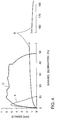
With reference to FIG. 4, test data were
recorded by graphically plotting the stress (as
measured in kpsi) experienced by the film versus the
strain (as measured by Graves elongation in %) that
the film underwent during the test. "Stress" is
defined as the recorded force divided by the product
of the film thickness and the ligament width
(distance "d" in FIG. 3). The expression "Graves
elongation" as used herein refers to the elongation
of a film in the tear direction as observed during a
Graves area test and reflects the percent change in
the jaw separation distance that occurs during the
test relative to the jaw separation distance at the
outset of the test. "Graves elongation at break" as
used herein refers to the elongation of the film in %
at its break point observed during the Graves area
test. (It will be understood that Graves elongation
at break differs from tensile elongation. Tensile
elongation is measured during a tensile test and may
be used to characterize ductile materials useful in
the invention as explained above.)
With continued reference to FIG. 4, the
plot (i.e., "curve") labeled with the letter "A"
describes a film having a large maximum stress which
falls off quickly as the film is stretched during the
test. Curve A typifies the performance of a high
modulus, stiff, dimensionally stable material which
has poor tear resistance (as shown by the rapid
falloff in stress as the film tears). Polyesters,
cellophane, biaxially oriented polypropylene and
similar packaging films perform similarly to curve A.
Curve A was obtained by measuring the performance of
the polyethylene terephthalate film of comparative
example 11, described more fully below.
The curve labeled with the letter "B"
describes the performance of a low modulus, ductile,
readily stretchable, traditionally tear resistant
material (as evidenced by the relatively high Graves
elongation at break relative to curve A) because the
film stretches rather than tears. The film is
capable of sustaining only a relatively low stress.
Plastic trash and grocery bags are common examples of
films that would perform in a manner similar to that
described by curve B. Curve B was obtained by
measuring the performance of the linear low density
polyethylene film of comparative example 12,
described more fully below.
Curve "C" illustrates the performance of a
multilayer film according to the invention and, more
specifically, the film of example 27 described below.
The maximum stress sustained by this film is similar
to or exceeds the stiff film of curve A. However,
the stress experienced by the curve C film of the
invention does not fall off as rapidly as in the case
of the curve A film. Thus, as compared to
conventional polyester films of curve A, films
according to the invention are more able to
successfully withstand catastrophic tearing forces
while being of substantially equal modulus. Such a
property is highly desirable in certain applications,
especially shatterproofing film for windows where the
impact from breaking glass may be sudden and
catastrophic. As compared to the low modulus films
of curve B, films of the invention are able to
sustain much higher stress. Thus, films according to
the invention are both stiff (high modulus) and tear
resistant.
In a Graves tear test, tear resistance data
are conventionally reported as the maximum force
experienced by the film. The data reported herein,
however, are the total area (referred to herein at
times as the "Graves area") beneath the stress-strain
curve (i.e., the curves of FIG. 4) which is obtained
by a mathematical integration of the curve. Graves
area is regarded as a measure of the total energy
required to cause the film to fail and, hence, a
measure of the film's combined stiffness and tear
resistance. Thus, Graves area may be regarded as a
measure of the ability of the film to absorb energy.
Graves area is reported herein in units of kpsi%
wherein 1 kpsi% = 69 kilojoules/cubic meter. It will
be understood that films with a relatively large
Graves area have enhanced combined stiffness and tear
resistance relative to those films with a relatively
small Graves area.
As shown more fully below, Graves area may
vary depending on whether the test is conducted in
the machine or the transverse direction of the film.
Also, Graves area generally increases with increasing
film thickness. As a general characterization, a
multilayer film may be regarded as tear resistant
within the scope of the invention if it demonstrates
a Graves area in one direction which exceeds the
Graves area (in the same direction) of a single layer
film that comprises only the stiff polyester or
copolyester used in the multilayer film, the single
layer film being processed (i.e., oriented, heat set,
etc.) in the same manner as the multilayer film and
to a substantially equal film thickness. Preferably
and more specifically, a multilayer film may be
regarded as tear resistant within the scope of the
invention if it demonstrates a Graves area at least
equal to 40 + 0.4(x) kpsi% in one direction (e.g.,
the machine or the transverse direction) of the film,
wherein x is the nominal thickness of the film in
microns.
Furthermore, and related to their overall
performance, multilayer films of the invention
preferably have a tensile modulus (when tested
according to ASTM Test Method D 882-88) of at least
175 kpsi (1,208 MPa) in one direction of the film,
more preferably at least 240 kpsi (1,656 MPa), and
most preferably at least 450 kpsi (3,105 MPa).
However, the actual modulus which is desirable will
depend on the application for which the film is
intended, some applications preferring relatively
stiffer films and others preferring relatively more
flexible films. In addition, and also related to
their overall performance, multilayer films according
to the invention desirably demonstrate a Graves
elongation at break of at least 20%, more preferably
at least 40% in the tear direction of the film
measured during the Graves area test.
The invention will be more fully
appreciated with reference to the following, non-limiting
examples.
Examples 1 to 26
A series of multilayer films comprising
alternating layers of a stiff polyester/copolyester
and a ductile sebacic acid based copolyester was
formed. A stiff polyethylene terephthalate (PET)
(differential scanning calorimetry (DSC) melting
point of 256°C; intrinsic viscosity of 0.60
deciliters per gram (dl/g) as measured in 60% phenol
and 40% dichlorobenzene at 110°C) was coextruded with
a ductile sebacic acid based copolyester. The
sebacic acid based copolyester comprised 40 mole %
sebacic acid and 60 mole % terephthalic acid as the
dicarboxylic acid components and 100 mole % ethylene
glycol as the diol component. The sebacic acid based
copolyester had an intrinsic viscosity in the range
of 0.9 to 1.05 dl/g when measured in the same fashion
as the PET. The ductile sebacic acid based
copolyester also displayed a tensile modulus of 14
kpsi (97 MPa) and a tensile elongation of 355% when
tested according to ASTM D822-88 at room temperature
using the ductile material test protocol described
above.
The multilayer films were coextruded onto a
chilled casting wheel and subsequently oriented
sequentially 2.6 times in the machine direction (MD)
at 80°C and 4.2 times in the transverse direction
(TD) at 99°C. The films were then heat set at
149°C.
The number of layers, the film thickness,
and the weight percent of the ductile sebacic acid
based copolyester were varied as shown below in Table
1. The tear resistance of the films in both the
machine and the transverse directions are reported
below in Table 1 as Graves area (rounded to the
nearest 10 here and for other examples) according to
the procedure described more fully hereinabove. The
Graves elongation at break values (rounded to the
nearest 5 here and for other examples) are also
reported in Table 1. The reported Graves area and
Graves elongation at break values throughout the
application (unless noted otherwise) are an average
of 9 readings in each of the machine and transverse
directions.
Although ASTM D 1004 utilizes a 0.5 inch
(1.3 cm) ligament (distance "d" in FIG. 3), examples
1 to 26 herein were analyzed using a 1.31 inch (3.3
cm) ligament. For examples 1 to 26, the observed
results were mathematically converted to a value
corresponding to a 0.5 inch (1.3 cm) ligament by
multiplying the observed Graves area result by 0.678
and adding 32.4, this conversion factor having been
determined by a linear regression analysis of
multiple samples. The observed results for Graves
elongation at break for examples 1 to 26 were also
mathematically converted so as to correspond to a 0.5
inch (1.3 cm) ligament by multiplying the observed
result by 0.655 and adding 11.3, this conversion
factor having been determined by a linear regression
analysis of multiple samples.
| Example | Number of Layers | Film Thickness (µm) | Wt. % of Ductile Material | Graves Area (kpsi%) | Graves Elongation at Break (%) |
| | | | | MD | TD | MD | TD | |
| 1 | 5 | 54.6 | 10 | 160 | 160 | 40 | 40 |
| 2 | 5 | 54.1 | 20 | 110 | 130 | 30 | 35 |
| 3 | 5 | 47.8 | 30 | 120 | 130 | 35 | 40 |
| 4 | 5 | 45.7 | 40 | 80 | 110 | 25 | 40 |
| 5 | 5 | 45.7 | 50 | 60 | 80 | 20 | 35 |
| 6 | 13 | 45.7 | 10 | 190 | 190 | 30 | 40 |
| 7 | 13 | 57.7 | 10 | 240 | 210 | 45 | 45 |
| 8 | 13 | 54.6 | 20 | 160 | 150 | 35 | 40 |
| 9 | 13 | 49.5 | 30 | 80 | 100 | 25 | 35 |
| 10 | 13 | 53.5 | 40 | 90 | 90 | 30 | 35 |
| 11 | 13 | 48.3 | 50 | 70 | 80 | 25 | 30 |
| 12 | 29 | 45.7 | 10 | 190 | 130 | 35 | 30 |
| 13 | 29 | 46.5 | 20 | 110 | 80 | 30 | 30 |
| 14 | 61 | 47.5 | 10 | 130 | 100 | 30 | 30 |
| 15 | 61 | 53.3 | 20 | 120 | 80 | 30 | 25 |
| 16 | 61 | 53.3 | 30 | 100 | 80 | 25 | 30 |
| 17 | 61 | 53.3 | 40 | 80 | 70 | 25 | 25 |
| 18 | 61 | 50.8 | 50 | 70 | 60 | 25 | 25 |
| 19 | 5 | 27.9 | 10 | 130 | 120 | 25 | 30 |
| 20 | 13 | 25.4 | 10 | 140 | 130 | 30 | 30 |
| 21 | 29 | 26.2 | 10 | 90 | 70 | 20 | 20 |
| 22 | 61 | 24.1 | 10 | 110 | 80 | 25 | 20 |
| 23 | 5 | 15.2 | 10 | 90 | 90 | 20 | 25 |
| 24 | 13 | 14.0 | 10 | 80 | 70 | 20 | 20 |
| 25 | 29 | 15.2 | 10 | 80 | 70 | 20 | 20 |
| 26 | 61 | 12.7 | 10 | 60 | 50 | 15 | 15 |
The data of Table 1 show that as the number
of layers in the film remains constant, the Graves
area of the film decreases as the amount of ductile
sebacic acid based copolyester increases above 10%.
The data of Table 1 further show that as the total
number of layers increases, the tear resistance of
the films tends to increase and then becomes more
constant or decreases as the number of layers
approaches 61, especially at lower wt. % amounts of
the ductile sebacic acid based copolyester.
Consequently, films according to the invention
comprise at least 3 layers, more preferably from 5 to
35 layers, and most preferably about 13 layers.
FIG. 5 is a graphical representation of the
data of examples 1 to 18, the plotted Graves area
being an average of the MD and TD values from Table
1. FIG. 5 illustrates the relationship among Graves
area, the wt. % of the ductile sebacic acid based
copolyester, and the number of layers in the film as
the total film thickness was attempted to be held
relatively constant. Using linear regression
analysis, the lines which "best fit" the data sets
(based on the number of layers in the film) were
drawn.
However, as shown in examples 19 to 26,
tear resistance is also related to film thickness and
the above trends may not always be rigidly observed
as film thickness decreases. Thicker multilayer
films generally have enhanced tear resistance
relative to thinner multilayer films when the number
of layers and the amount of ductile material are
essentially constant.
Comparative Examples 1 to 6
Comparative examples (C.E.) 1 to 6 report a
series of single layer films formed by extruding the
PET of examples 1 to 26 onto a chilled wheel. The
films were sequentially drawn 3.5 to 4 times in the
machine direction at about 85 to 90°C, and then about
4.5 times in the transverse direction at about 100°C.
The films were subsequently heat set at 220 to 225°C.
The films so produced were regarded as representative
of conventional, commercially available PET films
such as might be used in packaging applications.
The films were tested for Graves area in both the
machine and transverse directions according to the
procedure described above and with the results shown
below in Table 2.
(The processing conditions in the
preparation of these comparative examples were not
identical to those used in preparing examples 1 to
26. It will be understood by those of ordinary skill
in the art that adjustments in processing conditions
can affect film properties. However, the films of
comparative examples 1 to 6 are regarded as
representative of conventional, commercially
available PET films. Other comparative data which
replicate examples herein may be found. See example
27, for instance.)
| Example | Film Thickness (µm) | Graves Area (kpsi%) | Graves Elongation at Break (%) |
| | | MD | TD | MD | TD |
| C.E. 1 | 11.9 | 40 | 30 | 5 | 10 |
| C.E. 2 | 22.4 | 60 | 40 | 10 | 10 |
| C.E. 3 | 35.0 | 40 | 50 | 10 | 15 |
| C.E. 4 | 45.5 | 40 | 50 | 15 | 10 |
| C.E. 5 | 96.3 | 70 | 70 | 15 | 20 |
| C.E. 6 | 174.0 | 90 | 80 | 20 | 20 |
The data of examples 1, 6, 7, 12, 14, and
19 to 26 were graphically plotted in FIG. 6 to
illustrate the relationship among Graves area, film
thickness, and the number of layers as the wt. % of
the ductile material was held constant at 10%.
Separate curves were then constructed for the 5, 13,
29 and 61 layer films in both the machine and
transverse directions by serially connecting the data
points. Separate curves were also prepared in the
machine and transverse directions for the single
layer PET films of comparative examples 1 to 5.
(Comparative example 6 was not included in FIG. 6 in
order to facilitate data management and presentation
of the graph.) As shown in FIG. 6, multilayer films
according to the invention, virtually without
exception, demonstrated a Graves area which exceeded
that observed for the conventional PET films of
comparative examples 1 to 5, whether tested in the
machine or the transverse direction.
Also shown in FIG. 6 is the line defined by
the equation 40 + 0.4(x) kpsi% wherein x is the
nominal thickness of the film in microns. Multilayer
films according to the invention have Graves area
values which generally fall above this line whereas
the conventional PET films of comparative examples 1
to 5 have Graves area values which generally fall
below this line. Thus preferred multilayer films
comprising alternating layers of a stiff
polyester/copolyester, a ductile sebacic acid
copolyester and, optionally, an intermediate
material, according to the invention are considered
to be tear resistant if they demonstrate a Graves
area which is equal to or which exceeds 40 + 0.4(x)
kpsi% wherein x is the nominal thickness of the film
in microns. As explained above and related to their
overall performance, tear resistant films of the
invention also preferably exhibit a tensile modulus
(as determined in a conventional tensile test) in one
direction of the film of at least 175 kpsi (1,203
MPa), more preferably at least 240 kpsi (1,650 MPa),
and most preferably at least 450 kpsi (3,105 MPa), as
well as a Graves elongation at break (as determined
during the assessment of Graves area) of at least
20%, preferably at least 40%.
Example 27
A film comprising a total of 13 alternating
layers of the stiff PET of examples 1 to 26
coextruded with 5 weight % of the ductile material of
the same examples was prepared. The film was cast
onto a chilled quenching wheel, sequentially oriented
2.6 times in the machine direction at 86°C and 4.5
times in the transverse direction at 103°C, and heat
set at 149°C. The film was about 62 µm thick and
displayed a Graves area of 330 kpsi% in the machine
direction and 220 kpsi% in the transverse direction.
The film also exhibited a tensile modulus of 500 kpsi
in the machine direction and 700 kpsi in the
transverse direction. The Graves elongation at break
was 45% in each of the machine and transverse
directions. The multilayer film of this example was
used to prepare curve C of FIG. 4.
When a single layer film comprising only
the stiff PET of this example was extruded, biaxially
drawn and heat set in the same manner at a thickness
of about 66 µm, it demonstrated a Graves area of 120
kpsi% in the machine direction and 80 kpsi% in the
transverse direction. The single layer film also
displayed a tensile modulus of 530 kpsi in the
machine direction and 730 in the transverse direction
and a Graves elongation at break of 30% in each
direction. (Data reported for the single layer PET
film are an average of 5 measurements in each
direction.) Even though the tensile moduli of the
multilayer and single layer films were comparable,
the multilayer films demonstrated superior tear
resistance as measured by the Graves area test.
Comparative Examples 7 to 10
A series of comparative examples was
prepared by extruding the stiff and ductile materials
of examples 1 to 26 into a blended single layer film
rather than a multilayer film. The single layer
films were extruded onto a chilled casting wheel,
biaxially oriented 3.3 times in each of the machine
and transverse directions at 100°C, and heat set at
140°C. The weight % of the ductile material was
varied as shown below in Table 3 along with the
results of the Graves area and Graves elongation at
break tests, the reported data being an average of 5
measurements in each direction. The films were not
sufficiently uniformly thick to permit Graves area,
tensile modulus, and Graves elongation at break
testing at one thickness in both the machine and
transverse directions. Consequently, Table 3 also
reports the film thickness for testing in each
direction, the reported thicknesses being an average
of 5 measurements in each direction.
| Example | Wt. % of Ductile Material | Film Thickness (µm) | Tensile Modulus(kpsi) | Graves Area (kpsi%) | Graves Elongation at Break(%) |
| | | MD | TD | MD | TD | MD | TD | MD | TD |
| C.E. 7 | 0 | 33 | 39 | 640 | 640 | 70 | 100 | 20 | 30 |
| C.E. 8 | 5 | 43 | 25 | 420 | 450 | 80 | 110 | 30 | 35 |
| C.E. 9 | 10 | 27 | 38 | 440 | 570 | 80 | 80 | 30 | 25 |
| C.E. 10 | 30 | 80 | 59 | 410 | 420 | 80 | 110 | 30 | 35 |
Comparative examples 7 to 10 illustrate
that blends of stiff and ductile materials extruded
as single layer films do not exhibit any significant
improvement in tear resistance with the addition of a
ductile sebacic acid based copolyester. This is in
distinction to the benefits which are achieved by
coextruding the stiff and ductile materials into a
multilayer film according to the invention.
Comparative Example 11
Comparative example 11 describes the
preparation of the single layer PET film measured by
curve A of FIG. 4. More specifically, the PET of
examples 1 to 26 was melt extruded onto a chilled
casting wheel and then sequentially oriented 3.4
times in the machine direction at 88°C and 4.0 times
in the transverse direction at 110°C, followed by
heat setting at 232°C. The finished film was 51 µm
thick and demonstrated a Graves area of 30 kpsi% in
the machine direction and 37 kpsi% in the transverse
direction as well as a tensile modulus of 660 kpsi in
the machine direction and 650 kpsi in the transverse
direction. The film of this example is considered
representative of a conventional biaxially oriented
PET film.
Comparative Example 12
Comparative example 12 describes the
preparation of the single layer linear low density
polyethylene film measured by curve B of FIG. 4.
More specifically, TF0119F linear low density
polyethylene (hexene comonomer) having a density of
0.918 grams/cubic centimeter and commercially
available from Novacor Chemicals, Inc. (Calgary,
Alberta) was extruded and blown into a 51 µm thick
film. The blow up ratio was 3.2 and the draw down
ratio was 12.3. The film demonstrated a Graves area
of 182 kpsi% in the machine direction and 200 kpsi%
in the transverse direction due significantly to the
large Graves elongation (greater than 180%).
However, the film exhibited a relatively low stress.
The film of this example is considered representative
of films conventionally employed in the manufacture
of garbage and grocery bags.
Examples 28 to 31
Comparative Examples 13 and 14
A series of examples was prepared to
illustrate the improvement in tear resistance that is
possible when multilayer films comprising alternating
layers of stiff and ductile materials are oriented in
only one direction. More specifically, a series of
13 layer films having the composition of the film of
example 27 (the PET of examples 1 to 26 with 5 wt. %
of the ductile sebacic acid based copolyester of the
same examples) was extruded onto a chilled casting
wheel. A square sample of each film was clamped on
all four sides and drawn at 100°C 4.0 times in one
direction at a constant width while being restrained
in the transverse direction. The film was then heat
set at 150°C. The tear resistance and Graves
elongation at break of the film in the direction of
orientation (MD) and the direction perpendicular
thereto (TD) were tested as described above with the
results shown below in Table 4. Also evaluated and
reported in Table 4 as comparative examples 13 and 14
are two single layer films comprising the PET of
example 27 processed as described for examples 28 to
31.
| Example | Film Thickness (µm) | Graves Area (kpsi%) | Graves Elongation at Break (%) |
| | | MD | TD | MD | TD | |
| 28 | 89 | 80 | NT | 30 | NT |
| 29 | 117 | 40 | 540 | 50 | 105 |
| 30 | 131 | 20 | 540 | 10 | 110 |
| 31 | 252 | 60 | 440 | 25 | 110 |
| C.E. 13 | 90 | 10 | NT | 5 | NT |
| C.E. 14 | 120 | 10 | 400 | 10 | 90 |
| NT = Not tested |
These examples show that uniaxially
oriented multilayer films according to the invention
can offer improved tear resistance relative to single
layer films comprising only a stiff PET.
Examples 32 to 38
A series of examples was prepared to
illustrate the improvement in tear resistance that is
possible when the multilayer films comprise three
alternating layers of stiff and ductile materials.
More specifically, the stiff PET and the ductile
sebacic acid based copolyester of examples 1 to 26
were coextruded onto a chilled casting wheel in a
three layer configuration in which the two outer
layers comprised the stiff PET. The extruded films
were then sequentially biaxially oriented 2.6 times
in the machine direction at 100°C and 4.2 times in
the transverse direction at 100°C. The films were
then heat set at 149°C. The thickness of the films
and the weight percent of the ductile sebacic acid
based copolyester were varied as shown below in Table
5 along with the results from the Graves area and
Graves elongation at break testing of these examples.
The reported film thicknesses are an average of the
thicknesses of the samples tested in the machine and
transverse directions. The reported Graves area and
Graves elongation at break data are an average of 5
readings in each of the machine and transverse
directions.
| Example | Film Thickness (µm) | Wt. % of Ductile Material | Graves Area (kpsi%) | Graves Elongation at Break (%) |
| | | | MD | TD | MD | TD | |
| 32 | 48.9 | 3 | 330 | 150 | 65 | 50 |
| 33 | 48.9 | 5 | 250 | 110 | 55 | 30 |
| 34 | 52.2 | 10 | 260 | 60 | 55 | 20 |
| 35 | 65.2 | 20 | 270 | 70 | 70 | 35 |
| 36 | 63.8 | 30 | 140 | 70 | 40 | 30 |
| 37 | 55.0 | 40 | 110 | 30 | 40 | 20 |
| 38 | 55.9 | 50 | 90 | 40 | 45 | 25 |
A 68.8 µm thick single layer film
comprising only the stiff PET of these examples was
processed under the same conditions and found to have
a Graves area of 160 kpsi% in the machine direction
and 110 kpsi% in the transverse direction as well as
a Graves elongation at break of 40% in the machine
direction and 45% in the transverse direction.
Examples 32 to 38 illustrate that significant
improvements in tear resistance are possible over
single layer PET films when the multilayer film
comprises 3 layers. Examples 32 to 38 further show
the benefit of using less than 20 wt. % of the
ductile sebacic acid based copolyester and the
surprising improvement which is possible even when
amounts of 5 wt. % or less are employed.
Example 39
A multilayer film was prepared as described in
example 6 except that the ductile material comprised
60 mole equivalents terephthalic acid, 30 mole
equivalents sebacic acid and 10 mole equivalents
cyclohexane dicarboxylic acid. The film was
coextruded onto a chilled quenching wheel, and
simultaneously oriented about 3.3 times in the
machine direction and about 3.5 times in the
transverse direction, each at about 97°C. The film
was then heat set at about 149°C. The resulting
50 µm thick film demonstrated a Graves area of 70
kpsi% in the machine direction and 60 kpsi% in the
transverse direction with a Graves elongation at
break of 25% in each of the machine and transverse
directions.
Examples 40 to 42
Examples 40 to 42 were made in a manner
similar to example 39 but comprised different mole
equivalents of the sebacic acid and cyclohexane
dicarboxylic acid (CHDCA) components as shown below
in Table 6. The weight % of the ductile sebacic acid
based copolyester was also varied as reported in
Table 6 along with the results of the Graves area and
Graves elongation at break testing.
| Example | Sebacic Acid Equivalents | CHDCA Equivalents | Weight % Ductile Material | Graves Area (kpsi%) | Graves Elongation at Break (%) |
| | | | | MD | TD | MD | TD | |
| 40 | 20 | 20 | 5 | 90 | 70 | 25 | 25 |
| 41 | 25 | 15 | 10 | 80 | 80 | 25 | 25 |
| 42 | 35 | 5 | 10 | 70 | 70 | 25 | 25 |
Examples 39 to 42 illustrate that a portion
of the sebacic acid component may be replaced by
cyclohexane dicarboxylic acid. Sebacic acid based
copolyesters according to the invention may comprise,
in addition to terephthalic acid, 1 to 39 mole
equivalents sebacic acid and, correspondingly, 39 to
1 mole equivalents cyclohexane dicarboxylic acid,
wherein the mole equivalent contributions of these
three materials sums to 100.
As noted above, the combination of tear
resistance and high modulus provides the multilayer
films of the present invention with a unique ability
to absorb energy, especially in the event of a
catastrophic impact. Consequently, the multilayer
films disclosed herein are useful as security control
laminates for shatter-proofing glazing members
against impact or explosion. In such applications,
one or more tear resistant multilayer films are
applied to a glazing member as a shield that prevents
the fragmentation of the glazing member even though
it splinters or shatters upon breaking. When
adhesively bonded to a glazing member, security
control laminates based on the multilayer films of
the present invention provide excellent energy
absorption and distribution properties without
significantly delaminating from the glazing member.
The security control laminates are also less likely
to puncture and/or tear.
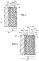
Turning now to FIG. 7, a glazing unit 20
comprises a security control laminate 21 bonded to
the interior face of a glazing member 22 by means of
an adhesive layer 23, such as those commonly used for
solar control or security films, including acrylate
pressure-sensitive adhesives and water activated
adhesives. Security control laminate 21 comprises a
first multilayer film 25 (having a first face 25a and
an opposed second face 25b) and a second multilayer
film 27 (having a first face 27a and an opposite
second face 27b) the two films being secured or
bonded together by a layer of a (polyester)
laminating adhesive 26.
In order to minimize the deteriorative
effects of ultraviolet (UV) radiation on any of the
polymeric materials which comprise the security
control laminate, it is highly desirable to interpose
a coating 24, containing a UV absorber, between
multilayer film face 25b and adhesive layer 23.
Alternatively, means for absorbing UV radiation may
be incorporated into adhesive layer 23 or multilayer
film 25. Suitable UV absorbent coatings may include
substituted benzophenones and substituted
benzotriazenes.
Multilayer film face 27b optionally
includes a thin, abrasion resistant coating 28
thereon to protect film 27 from mechanical abrasion
such as might occur during installation or cleaning
of the security control laminate. Suitable abrasion
resistant coatings comprise photopolymerized
materials such as the "hydantoin hexacrylate"
coatings described in U.S. Pat. No. 4,249,011
(Wendling), which is incorporated herein by
reference, or other photopolymerizable
multifunctional acrylates.
Although FIG. 7 illustrates the security
control laminate on the interior face of the glazing
member (i.e., the face of the member which is
opposite to the face first exposed to the force of
the impact), the laminate may also be secured to the
exterior face. Also contemplated is a glazing unit
comprising multiple glazing members arranged in, for
example, a sandwich or an insulated construction
wherein the security control laminate is secured to a
face of a glazing member which is interior to the
sandwich or insulated construction. Additionally, it
is contemplated that the security control laminate
may be adhesively or mechanically attached to a
supplemental frame or batten system that surrounds
the glazing member as well as to the glazing member
itself. An installation of this type provides
additional security against unintended removal or
dislodgement of the glazing member from its frame
which would otherwise allow access through the
glazing unit.
FIG. 8 illustrates a second embodiment of
security control laminate 21 which additionally
includes a reflective metalized layer 30 to impart
energy control properties to the glazing unit. This
embodiment is similar to the security control
laminate illustrated in FIG. 7 except that metalized
layer 30 is adjacent to multilayer film face 27b
rather than abrasion resistant coating 28.
More particularly, a carrier film 31
supports metalized layer 30, the latter being bonded
to multilayer film face 27b by an adhesive layer 29.
Metalized layer 30 may be aluminum, gold, silver,
copper, nickel, or any other suitable reflector of
radiant energy over the solar and infrared spectrum
(i.e., a wavelength of 0.3 to 40 µm). Metalized
layer 30 may be applied to carrier film 31 by, for
example, vapor deposition. Preferably, metalized
layer 30 is relatively transparent to visible light
and offers good reflectivity of infrared radiation.
Carrier film 31 comprises an optically clear film,
preferably an optically clear polyester film, having
a thickness in the range of about 13 to 51 µm (0.5 to
2.0 mils). Optionally, carrier film 31 may be dyed
to provide additional protection from radiation
incident on the glazing unit. In this regard, any
optical grade dyed film may be used. Such films
typically comprise an optically clear polyester film
which has been dipped in a heated solvent bath
containing a dye of the desired (and often
customized) color, washed, rinsed and dried. Films
of this type are commercially available from Martin
Processing Company (Martinsville, VA). Adhesive
layer 29 may be a laminating adhesive similar to
adhesive layer 26 for example. The embodiment of
FIG. 8 may (but need not) include abrasion resistant
coating 28 on the face of carrier film 31 which does
not support metalized layer 30.
FIG. 9 illustrates a third embodiment of
security control laminate 21 which utilizes a single
multilayer film 25. The embodiment of FIG. 9 is
similar to those described in conjunction with FIGS.
7 and 8 with the exception that multilayer film 27
has been replaced by a dyed film 32 that is secured
to multilayer film face 25a by way of adhesive layer
26. Abrasion resistant coating 28 protects the
opposite face of dyed film 32 from mechanical
abrasion. Dyed film 32 is similar to the dyed
version of carrier film 31 described in conjunction
with FIG. 8.
Constructions other than those illustrated
above comprising different arrangements of multilayer
films, metalized films, and/or dyed films are also
possible. Such other constructions may offer various
security and/or solar control properties as will be
appreciated by the skilled artisan. Furthermore,
while certain coatings and layers may be described
herein as being "on" other coatings and layers of the
security control laminate, it will be understood that
this encompasses both direct and indirect attachment
to the other coatings or layers.
FIG. 10 illustrates the security control
laminate of FIG. 8 before installation on a glazing
member. Overcoat 33, which preferably is a water
soluble material, is applied over adhesive layer 23
to protect it from damage during manufacture and
handling. A variety of water soluble materials such
as methyl cellulose or polyvinyl alcohol are suitable
as the overcoat material. Security control laminate
21 is temporarily disposed on a removable release
liner 34 which is discarded prior to installation of
the laminate on the glazing member. Release liners
typically employed with solar control and security
films may be used. The security control laminate is
prepared for application by removing the release
liner and rinsing the laminate with water to remove
overcoat 33, thereby exposing and/or activating
adhesive layer 23. Security control laminate 21 is
then applied to the glazing member using conventional
installation techniques known in the art.
The following examples illustrate the
particular utility of multilayer films according to
the invention in providing security control laminates
for glazing members. In these examples all parts and
percentages are by weight and all film and layer
thicknesses are nominal thicknesses. Single pane
window glass panels having a security control
laminate according to the invention applied to one
face thereof were tested for their ability to
withstand impact without puncture and/or tearing in
accordance with a modified version of American
National Standards Institute's Specification for
Safety Glazing Material Used in Buildings, ANSI
Z97.1-1984. In general, tests were conducted by
swinging a weighted shotbag into 0.3 cm and/or 0.6 cm
thick glass panels in a pendulum arc, dropping the
bag from heights of 45.7 cm (18 inches) and 122 cm
(48 inches). (The shotbag impacted the surface of
the glass panel which did not have the security
control laminate bonded thereto.) The heights used
will be recognized as corresponding to levels II and
III of ANSI Z97.1-1984. The ANSI test setup was
utilized but different numbers of panels were tested
at less than all of the levels specified in the
published procedure. An individual panel was
considered to have met the test requirements, if,
after impact, a 7.6 cm diameter metal ball mounted on
a rod could not be passed through any break in the
panel resulting from the impact.
Example 43
A multilayer film comprising 13 alternating
layers of the stiff PET of examples 1 to 26 and the
ductile copolyester of the same examples was
coextruded onto a chilled casting wheel and
subsequently sequentially oriented 2.6 times in the
machine direction at about 85°C to 90°C and 3.3 times
in the transverse direction at 99°C. The resulting
58 µm thick film was heat set at 149°C and comprised
7 wt. % of the ductile material.
One surface of the multilayer film was
corona treated to a surface energy of 40 to 44
dynes/cm under standard corona treating conditions
using an apparatus available from Enercon Industries.
Adhesive was applied to the corona treated
surface of the multilayer film by coating a 14.5%
solids solution of a pressure sensitive adhesive
comprising 100 parts of a 96:4 isooctyl
acrylate:acrylamide copolymer (prepared as described
in U.S. Pat. No. Re. 24,906 to Ulrich, which is
incorporated herein by reference), 2 parts of a UV
absorber (UNIVUL D-50, commercially available from
BASF), 0.8 part of a fluorochemical surfactant (FC-740,
commercially available from Minnesota Mining and
Manufacturing Company), and 0.5 part of a substituted
phenolic thioether antioxidant (SANTINOX-R,
commercially available from Monsanto Company) in a
solvent system comprising 33 parts heptane, 32 parts
ethyl acetate, 29.5 parts toluene, and 6 parts methyl
ethyl ketone. The coated multilayer film was then
dried in a circulating air oven operating at 105°C
for approximately 3 minutes to remove the solvent and
to provide a pressure sensitive adhesive having a dry
coating weight of 22.6 grams/square meter (g/m2). A
1.6% solids overcoat solution of METHOCEL A15LV
(commercially available from Dow Chemical Co.) was
applied over the pressure-sensitive adhesive and the
water was evaporated by passing the coated film
through a circulating air oven operating at 63°C for
approximately 1 minute to provide a tack-free, water
soluble coating of 0.3 g/m2 dry weight.
A 25 µm thick release liner comprising a
release agent coated PET film was removably laminated
to the METHOCEL coating by passing the construction
through a pair of squeeze rolls to provide a security
control laminate according the invention.
The release liner was removed, the film
laminate was rinsed with water to remove the METHOCEL
coating, and the security control laminate was
applied to both 0.3 cm thick and 0.6 cm thick clean
glass panels measuring 86.4 cm by 193 cm using
standard installation techniques for solar and
security films. The resulting panels were dried at
room temperature for six weeks before impact testing
as previously described. Six panels (3 having a
thickness of 0.3 cm and 3 having a thickness of 0.6
cm) were tested at a drop height of 45.7 cm. All 6
panels met the test requirements. When 4 panels (2
of each thickness) were tested at the 122 cm drop
height, none met the test requirements.
Examples 44 to 46
A series of security control laminates,
each comprising two identical multilayer tear
resistant films according to the invention, was
prepared. Each multilayer film was 51 µm thick and
comprised 13 alternating layers of the stiff PET of
examples 1 to 26 and 5.6 wt. % of the ductile
polymeric material of the same examples. The films
were coextruded onto a chilled casting wheel and were
simultaneously biaxially oriented 3.3 times in each
of the machine and transverse direction at 99°C. The
multilayer films of examples 44 to 46 differed only
in the temperature at which they were heat set. The
film of example 44 was heat set at 149°C, the film of
example 45 was heat set at 163°C, and the heat set
temperature for the film of example 46 was 177°C.
A toluene/methyl ethyl ketone (T/MEK) solution (3.7:1
weight to weight ratio) of a tack free, polyester
laminating adhesive was prepared by combining 6%
VITEL PE-307 (commercially available from Goodyear
Chemicals) and 0.3% MONDUR CB-75 (a curing agent
available from Mobay Chemical Company). The solution
was coated onto one of the multilayer films for each
example and the coated films were dried in a
circulating air oven operating at 63°C for
approximately 2 minutes to provide dry adhesive
coatings of approximately 0.8 g/m2.
The second multilayer film for each example
was laminated to the adhesive coated surface of the
first multilayer film by passing the layered
structures through a pair of squeeze rollers
operating at 75°C and 207 dynes/cm2 (30 psi). The
dual film laminates were then corona treated, coated
with a pressure sensitive adhesive and overcoat, and
provided with a removable release liner, all as
described more fully in example 43.
The panels were prepared and tested for
impact resistance as described above using 0.6 cm
thick glass panels and a 122 cm drop height. In
example 44, 8 of the 10 panels tested met the test
requirements, while 5 of the 10 panels did for
example 45, and 4 of the 10 panels did for example
46. Thus, examples 44 to 46 suggest that the
performance of security control laminates according
to the invention can be varied by appropriate
selection of the temperature at which the multilayer
film is heat set. For use in security control
laminates, the multilayer films of the invention are
preferably heat set at about 145°C to 165°C, more
preferably about 149°C.
Comparative Example 15
Comparative example 15 was a 102 µm thick
commercially available security control film that
comprised a pair of 51 µm thick biaxially oriented
single layer PET films laminated together.
Essentially, the security control laminate of
comparative example 15 was like that of example 44
except that it employed single layer PET films rather
than the multilayer films of the invention.
Comparative example 15 was tested according to the
procedure of example 43. 6 panels (3 of each
thickness) evaluated at the 45.7 cm drop height met
the test requirements. One panel (0.3 cm thick
glass) was tested at 122 cm and met the test
requirements.
Example 47
The tack free, polyester laminating
adhesive of examples 44 to 46 is coated onto the
multilayer film of example 44 and the coated film is
dried in a circulating air oven operating 63°C for
approximately 2 minutes to produce a dry adhesive
coating of approximately 0.8 g/m2. A second
multilayer film of the same example is laminated to
the adhesive coated surface of the first multilayer
film by passing the layered structure through a pair
of squeeze rollers operating at 75°C and 207 dynes/cm2
(30 psi) to provide a dual film laminate.
A 25 µm thick biaxially oriented PET
carrier film is vapor coated with aluminum to a sheet
resistance of approximately 9 ohms/square using
standard vapor coating techniques. The visible
spectrum transmission of the aluminum coated film is
approximately 18% at a wavelength of 0.55 µm. The
tack free polyester laminating adhesive of example 44
is then coated onto the aluminum surface of the PET
carrier film and dried to provide a dry adhesive
coating of approximately 0.8 g/m2. The resulting
adhesive coated PET carrier film is then laminated to
the uncoated surface of the dual film laminate by
passing the layered structure through a pair of
squeeze rollers operating at 75°C and 207 dynes/cm2
(30 psi).
The exposed surface of the carrier film is
corona treated as described in example 43 and a
solution consisting of 100 parts hydantoin
hexacrylate (HHA), 4 parts IRGACURE 184 (a
photoinitiator commercially available from Ciba-Geigy
Corporation), and 418 parts MEK is immediately coated
onto the corona treated surface. The coated
construction is then passed through a circulating air
oven operating at 49°C for approximately 3 minutes to
provide an HHA coating of approximately 2.7 g/m2. The
HHA coating is then cured by passing the construction
under three banks of 200 watts/inch medium pressure
mercury vapor UV lamps at a line speed of 30.5
meters/minute (100 feet/minute) and a lamp to film
distance of 12 cm to provide an abrasion resistant
coating.
A UV absorbent composition is prepared by
combining 7.5 parts of a substituted benzophenone
(e.g., UVINUL M-493 or UVINUL D-50, commercially
available from BASF), 92.5 parts VITEL PE-222 (a PET
terpolymer commercially available from Goodyear
Chemicals), and a sufficient volume of a 1:1 weight
to weight ratio T/MEK solvent system to produce a 26%
solids solution.
The uncoated surface of the multilayer film
laminate is corona treated to a surface energy of 40
to 44 dynes/cm (using an apparatus available from
Enercon Industries) and the above described UV
absorbing composition is immediately coated onto the
corona treated surface. The coated laminate is then
passed through a circulating air oven operating at
65°C for approximately 2 minutes to provide a UV
absorbent layer having a dry coating weight of 5.4
g/m2. A pressure sensitive adhesive layer is coated
over the UV absorbing composition according to
example 43 (where it was applied directly to the
corona treated surface) to a dry coating weight of
22.6 g/m2. The adhesive layer is then overcoated
with a tack-free, water activatable METHOCEL layer.
A 25 µm thick release liner (such as used in example
43) is removably laminated to the METHOCEL coating by
passing them through a pair of squeeze rolls.
Example 48
Example 48 is similar to example 47 except
that the aluminum vapor coated PET carrier film is
replaced with a dyed PET film such as an optically
clear dyed film commercially available from Martin
Processing Company (Martinsville, VA) that is
laminated to the dual film construction.
Reasonable variations and modifications are
possible within the scope of the foregoing
specification and drawings without departing from the
invention which is defined in the accompanying
claims.