EP0591985A1 - Glenoid alignment guide and method of use - Google Patents
Glenoid alignment guide and method of use Download PDFInfo
- Publication number
- EP0591985A1 EP0591985A1 EP93116322A EP93116322A EP0591985A1 EP 0591985 A1 EP0591985 A1 EP 0591985A1 EP 93116322 A EP93116322 A EP 93116322A EP 93116322 A EP93116322 A EP 93116322A EP 0591985 A1 EP0591985 A1 EP 0591985A1
- Authority
- EP
- European Patent Office
- Prior art keywords
- glenoid
- guide
- drill
- neck
- drill guide
- Prior art date
- Legal status (The legal status is an assumption and is not a legal conclusion. Google has not performed a legal analysis and makes no representation as to the accuracy of the status listed.)
- Withdrawn
Links
Images


Classifications
-
- A—HUMAN NECESSITIES
- A61—MEDICAL OR VETERINARY SCIENCE; HYGIENE
- A61B—DIAGNOSIS; SURGERY; IDENTIFICATION
- A61B17/00—Surgical instruments, devices or methods, e.g. tourniquets
- A61B17/16—Bone cutting, breaking or removal means other than saws, e.g. Osteoclasts; Drills or chisels for bones; Trepans
- A61B17/17—Guides or aligning means for drills, mills, pins or wires
- A61B17/1739—Guides or aligning means for drills, mills, pins or wires specially adapted for particular parts of the body
- A61B17/1778—Guides or aligning means for drills, mills, pins or wires specially adapted for particular parts of the body for the shoulder
-
- A—HUMAN NECESSITIES
- A61—MEDICAL OR VETERINARY SCIENCE; HYGIENE
- A61F—FILTERS IMPLANTABLE INTO BLOOD VESSELS; PROSTHESES; DEVICES PROVIDING PATENCY TO, OR PREVENTING COLLAPSING OF, TUBULAR STRUCTURES OF THE BODY, e.g. STENTS; ORTHOPAEDIC, NURSING OR CONTRACEPTIVE DEVICES; FOMENTATION; TREATMENT OR PROTECTION OF EYES OR EARS; BANDAGES, DRESSINGS OR ABSORBENT PADS; FIRST-AID KITS
- A61F2/00—Filters implantable into blood vessels; Prostheses, i.e. artificial substitutes or replacements for parts of the body; Appliances for connecting them with the body; Devices providing patency to, or preventing collapsing of, tubular structures of the body, e.g. stents
- A61F2/02—Prostheses implantable into the body
- A61F2/30—Joints
- A61F2/40—Joints for shoulders
- A61F2/4081—Glenoid components, e.g. cups
Definitions
- This invention relates to a glenoid alignment guide to assist in the preparation of the glenoid during surgery to replace a shoulder joint with an implant.
- the preparation of the glenoid during shoulder surgery to receive a plastic or metal implant relies upon the surgeon being able to identify the axis of the bone and locate the implant within the maximum bone stock. Access to the glenoid is limited by the depth of the structure in the wound and the surrounding tissue as well as the surgical technique used.
- the anatomy of the glenoid and scapula is such that there is very little bone into which an implant can be placed.
- the articulating surface of the joint consists of a shallow dished cartilaginous area bonded by soft tissue of the rotator cuff which stabilizes the humeral head against the glenoid.
- the glenoid is roughly oval to pear-shaped and most replacement implants follow this contouring for optimal fit. Whilst the lateral aspect of the glenoid presents a broad surface for articulation, the margins taper rapidly medially to form a narrow neck of about 10 to 15mm thickness from which emerge the coracoid (superiorly) and acromial (posteriorly) processes. The thinning of the glenoid progresses into the scapula bone where the thickness may be as little as 2mm to 3mm, although there is a broader spine running along the inferior margin of the scapula.
- the axis of the visible face of the glenoid is easily identified, but does not correspond to the axis of the glenoid neck which is oriented posteriorly behind the glenoid face.
- the amount of bone in the neck in line with the axis of the visible glenoid is therefore greatly reduced and so it is along the actual axis of the glenoid neck that the anchoring means of the implant needs to be positioned.
- disease or degeneration can severely restrict the size of the glenoid, making implant placement more problematic.
- the scapula is a floating bone which is highly mobile, presenting little resistance to pressure, particularly under anaesthesia.
- the invention therefore has been made with these factors in mind.
- the invention provides a glenoid alignment guide adapted to retract soft tissue and muscle away for the glenoid, and guide a drill bit into the glenoid in proper alignment with the glenoid neck and glenoid face of a patient.
- the glenoid alignment guide comprises a retractor plate for displacing the posterior and superior aspect of the deltoid muscle, and a drill guide slidably carried on the retractor plate.
- the retractor plate has a curved finger narrower than the plate defining the forward end of the retractor plate.
- the finger is adapted for insertion behind the glenoid.
- the tip of the finger is arranged to engage the bone of the glenoid neck to form a fulcrum for levering the muscle and other tissue clear of the glenoid.
- the drill guide defines an axial path along which a drill bit is guided.
- the drill guide is movable along the retractor plate to a forward position for engagement with the glenoid face.
- Guide means e.g., a guide hole
- Guide means is provided in the drill guide for guiding a drill bit along the axial path to make a hole from the glenoid face into the glenoid neck along the axis of the glenoid neck to receive fastening or locating means of a glenoid component of a shoulder implant.
- the tip of the retractor plate when engaged against the bone of the glenoid neck aligns the axial path defined by the drill guide relative to the glenoid neck.
- the tip of the finger has serrations adapted for non-slip engagement with the neck of the glenoid, and the tip of the finger is spaced radially from the center of the axial path defined by the guide means by 1.5mm to 2.5mm plus the radius of the drill bit to be guided by the guide means.
- the tip of the finger is spaced radially from the center of the axial path of the guide means by 2.0mm to 2.5mm plus the radius of the drill bit to be guided by the guide means.
- the glenoid alignment guide is adapted among other things for improved viewing of the glenoid face.
- the drill guide may have a periphery and a plurality of cut away portions around the periphery to improve the view of the glenoid face as the drill guide is advanced. This allows the glenoid face to be viewed through the cut away portions of the drill guide to facilitate centering the drill guide relative to the glenoid face.
- the drill guide has a generally convex-curved frontal surface adapted to correspond to the generally concave-curved surface of the glenoid face of the glenoid.
- the locking means may comprise a rod projecting rearwardly from the drill guide, a pivotable locking lever having a hole with an elongate cross section through which the rod passes, and resilient urging means for urging the locking lever such that the rod is gripped by the edges of the hole.
- the arrangement is such that retraction of the drill guide is resisted by the gripping of the rod by the locking lever but is possible if the locking lever is manually pivoted against the urging force of the resilient urging means to release the rod.
- the retractor plate has a track mounting the drill guide on the retractor plate for sliding movement of the drill guide along the track in the axial direction.
- the track constrains the drill guide from rotation relative to the retractor plate, with the drill guide being mounted on the rod to move axially together with the rod to allow advancing the drill guide along the track of the retractor plate by manually moving the rod.
- the retractor plate has a main body having opposite side edges, and ribs extending from the main body along the opposite side edges to define the track.
- the drill guide has a rear surface, and a collar is fitted around the drill bit for engaging the rear surface of the drill guide to limit the penetration of the drill bit into the glenoid bone.
- Such a guide can assist the surgeon in both obtaining good exposure of the glenoid and location for drilling a hole for fixing an implant.
- the finger can be relatively narrow and so damage to nerves and blood vessels behind the glenoid can be kept to a minimum as it is inserted and its tip, when engaged with the bone, will identify the thinnest part of the glenoid neck so aligning the drill guide for optimum drilling.
- the neck of the glenoid is of reasonably consistent width in all patients and once the tip of the finger engages it, one can be sure that the drill guide will be well positioned and ensure that, when the surgeon drills a hole, it will pass along the bone in the neck and not penetrate through the neck.
- the retractor plate is inserted between the patient's soft tissue and muscle and the glenoid, and the tip of the finger is placed against the glenoid neck. With the tip of the finger against the glenoid neck, the tissue and muscle is levered aside to expose the glenoid face, by means of the retractor plate. Then, with the tip of the finger remaining against the glenoid neck, the drill guide is advanced to a position where the drill guide abuts the glenoid face.
- the drill guide is used to align a drill bit for drilling a hole along the axial center of the glenoid neck to receive fixing means of the implant.
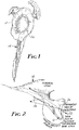
- the neck 10 of the glenoid 12 of a human scapular 14 is very narrow, particularly as viewed in the superior orientation shown in Figure 2. It is therefore important when making a drilled hole 63 into the glenoid 12 to receive the fixing screw of an implant, to ensure that the axis of the drilled hole 63 passes along the actual axis 22 of the glenoid 12, and not along the apparent axis 24 which is the one visible to a surgeon who can only see the articulating face 26 of the glenoid, the rest of the glenoid being covered by the deltoid muscle, tendons and other tissue, etc.
- a glenoid alignment guide 30 as shown in Figures 3 to 5 is used by a surgeon to assist in identifying this axis 22.
- This alignment guide 30 includes a retractor plate 32 which is used to displace the posterior and superior aspects of the deltoid muscle to assist in placing the glenoid alignment guide against the glenoid articulating face 26.
- the retractor plate 32 has a handle 33 to assist in manoeuvering the glenoid alignment guide 30, whilst at its front it has an integral curved finger 34 with a tip 36.
- This curved finger 34 acts as a fulcrum for the retractor plate 32 when the surgeon inserts the finger 34 behind the glenoid 12 and can then use the retractor plate 32 to lever muscle and the tissue clear of the glenoid face 26.
- the finger 34 is narrower than the retractor plate 34 so as to reduce the damage to nerves and blood vessels which run behind the glenoid face 26.
- the tip 36 is not, however, pointed, or so narrow that it will penetrate into the bone as the powerful deltoid muscle is levered out of the way by the alignment guide 30.
- the tip 36 preferably has serrations as shown, or forked (not shown), to provide a secure non-slip engagement with the glenoid neck 10 so that the tip 36 does not slip as the muscle, etc. is being levered clear.
- the plate 32 therefore, assists the surgeons by ensuring that the glenoid 12 and particularly its face 26 are fully exposed.
- the tip 36 of the finger 34 also serves as a guide.
- the surgeon locates the narrowest part of the glenoid neck with this finger 34.
- the glenoid alignment guide 30 is located so that an eventual hole 63 drilled using the alignment guide 30, as will be described, will be along the axis 22 ( Figure 2), and so make best use of the available bone and will not break through the bone.
- a drill guide 40 is slidably mounted on the retractor plate 32.
- the drill guide 40 includes a front portion 41 and an integral rear portion 42.
- the retractor plate 32 has upstanding ribs or edges 32a which, as best shown in Figure 6, are slightly above the central surface 32b of the surface of the retractor plate 32 to define a track for slidably mounting the drill guide 40. These edges 32a engage side wing portions 42a extending from the rear portion 42 of the drill guide 40.
- Attached to and extending rearwardly from the rear portion 42 of the drill guide 40 is a rod or shaft 43 which is slidably mounted in a block 44 fixed to the retractor plate 32. The mounting of the shaft 43 and the engagement of the sides of the drill guide 40 with the edges 32a, ensures that the drill guide 40 is constrained to move axially along the retractor plate 32.
- the front face 46 of the drill guide 40 is convex-curved and designed to engage and approximately match the generally concave-curved articulating face 26 of the glenoid.
- three cut-outs 48 are provided to improve the surgeon's view of the face 26 when the drill guide 40 is brought to abut the face 26 as will be described.
- the cut outs 48 allow the surgeon to see the glenoid face and asses the correct size of implant to choose to be fitted.
- the cut outs are positioned so as to coincide with the positioning of the small stabilizing screws which are used to prevent rotation of the fitted implant, and so facilitate the surgeon's assessment of whether one or more such screws can be satisfactorily positioned.
- a locking mechanism 50 is provided.
- This comprises a locking lever or clamp 52 pivotally mounted on the retractor plate 32, having a forwardly-bent portion 52a, and having a hole 54 having an elongate cross section ( Figure 7) through which the shaft 43 extends, and a coil spring 56 positioned around the shaft 43 between the block 44 and the clamp 52.
- the arrangement is such that the coil spring 56 normally pushes the locking clamp 52 in a rearward direction, the edges of the hole 54 clamping the shaft 43 and preventing its rearward movement.
- the drill guide 40 and shaft 43 can however be pushed forwardly since such movement will release the clamping action of the clamp 52 and temporarily overcome the spring force.
- the drill guide 40 has a central through hole 60, and this is used to align a drill bit 62.
- the through hole 60 has a cross section sized to closely receive the drill bit 62 to provide adequate guidance of the drill bit 62. Therefore the surgeon can now drill a drilled hole 63 in the glenoid as shown in Figure 5.
- the axial path or axis 60a of the through hole 60 along which the drill bit 62 will be advanced is spaced approximately 2mm to 2.5mm plus the radius of the drill bit 62 from that tip 36 of the finger 34.
- the spacing 64 ( Figure 5) between path of the drill bit 62 and the tip 36 is preferably 2mm to 2.5mm. This ensures that hole 63 is made approximately in the center, in the sense viewed in Figure 5, of the glenoid neck 10.
- the through hole 60 is sized to closely receive the drill bit 62, one alternative way of expressing this is that the tip 36 of the finger 34 is spaced from the extended central axis 60a of the through hole 60 by a distance approximately equal to the radius of the through hole 60 plus 2mm to 2.5mm.
- the glenoid neck 10 has a dimension, in the direction of the arrow 65 ( Figure 5), which is typically 10mm and almost never more than 12mm. Assuming therefore that the drill bit 62 has a diameter of 5mm, this leaves a thickness of 5mm, or exceptionally, 7mm of bone, and so 2.5mm, i.e., half the typical 5mm of available bone, is the preferred maximum spacing of the tip 36 of the finger 34 from what will be the hole 63 which is drilled. In case the dimension of the glenoid neck 10 may be slightly less than 10mm, however, this spacing 64 should be less than that maximum, e.g., 2mm, and desirably no less than 1.5mm. By choosing the spacing 64, to be 1.5mm to 2.5mm and most preferably approximately 2mm, one can therefore ensure that the drilled hole 63 is approximately centered in the glenoid neck 10 in the sense of the arrow 65.
- the alignment of the drilled hole 63 in the sense transverse to the direction of the arrow 64 is not as critical and so small variations of the alignment of the drilled hole 63 in the sense transverse to the plane of the Figure 5, is not usually too critical.
- a cylindrical sheath or collar 66 is fitted over the drill bit 12 before it is inserted through the through hole 60 of the drill guide 40. This collar 66 prevents excessive drilling of the glenoid 12 since it will engage the rear face of the drill guide 40 when the depth of the drilled hole 63 is sufficient, normally 20 to 25mm. Thus the drill bit 12 should not be allowed to penetrate through the back of the scapular.
- the through hole 60 of the drill guide 40 guides and aligns the axis of the drilled hole 63 which is drilled and the sheath 66 abuts the rear face of the rear portion of the drill guide 40 when the hole 63 has been drilled to sufficient depth, so limiting the depth of the drilled hole 63. Both arrangements therefore prevent the drill bit 12 and drilled hole 63 from breaking through the neck 10.
- the drill guide 40 can thereafter be retracted and the alignment guide 30 removed to allow subsequent steps in the fitting of the implant which may include preparation of the glenoid articulating surface, tapping of the hole 63, and securing of the implant by screwing into the tapped hole 63.
- steps form no part of the present invention and so need no further explanation. They are, however, steps which are known and understood by the surgeon.
Abstract
A glenoid alignment guide (30) for aligning a drill bit relative to the glenoid and the glenoid neck of a patient. The alignment guide comprises a retractor plate (32) for displacing the posterior and superior aspect of the deltoid muscle, and a drill guide (40) slidably movable along the retractor plate. The tip (36) of a narrow, curved finger (34) on the retractor plate is adapted to engage the bone of the glenoid neck to form a fulcrum for levering the muscle and other tissue clear of the glenoid. When the tip of the retractor plate engages the glenoid neck and the drill guide is advanced along the retractor plate against the glenoid face, the drill guide is adapted to guide a drill bit to make a hole from the glenoid face into the glenoid neck along the axis of the glenoid neck. This hole is then used to receive a fastener or locating peg of a glenoid component of a shoulder implant. The method of using the alignment guide is also disclosed.
Description
- This invention relates to a glenoid alignment guide to assist in the preparation of the glenoid during surgery to replace a shoulder joint with an implant.
- The preparation of the glenoid during shoulder surgery to receive a plastic or metal implant relies upon the surgeon being able to identify the axis of the bone and locate the implant within the maximum bone stock. Access to the glenoid is limited by the depth of the structure in the wound and the surrounding tissue as well as the surgical technique used.
- The anatomy of the glenoid and scapula is such that there is very little bone into which an implant can be placed. The articulating surface of the joint consists of a shallow dished cartilaginous area bonded by soft tissue of the rotator cuff which stabilizes the humeral head against the glenoid.
- The glenoid is roughly oval to pear-shaped and most replacement implants follow this contouring for optimal fit. Whilst the lateral aspect of the glenoid presents a broad surface for articulation, the margins taper rapidly medially to form a narrow neck of about 10 to 15mm thickness from which emerge the coracoid (superiorly) and acromial (posteriorly) processes. The thinning of the glenoid progresses into the scapula bone where the thickness may be as little as 2mm to 3mm, although there is a broader spine running along the inferior margin of the scapula.
- The axis of the visible face of the glenoid is easily identified, but does not correspond to the axis of the glenoid neck which is oriented posteriorly behind the glenoid face. The amount of bone in the neck in line with the axis of the visible glenoid is therefore greatly reduced and so it is along the actual axis of the glenoid neck that the anchoring means of the implant needs to be positioned. In addition, disease or degeneration can severely restrict the size of the glenoid, making implant placement more problematic. Further the scapula is a floating bone which is highly mobile, presenting little resistance to pressure, particularly under anaesthesia.
- There are several problems for the accurate and satisfactory placement of an implant including:
- 1. access to the glenoid;
- 2. identification of the axis of the glenoid;
- 3. the alignment of the implant against the glenoid face,
- 4. the alignment of the anchoring means for the implant in the glenoid bone, and
- 5. the risk of glenoid neck fracture or exposure and penetration of the anchoring means through the wall of the bone.
- To date the placement of an implant has depended upon the surgeon visually assessing the axis of the glenoid. He can gain access to and see the glenoid. However, the deltoid muscle, tendons and other tissue obscure the glenoid neck and it is undesirable to disturb this region unnecessarily. Therefore, the surgeon has had little or no actual knowledge of the anatomy behind the face of the glenoid, particularly the thickness and orientation of the neck which as noted above does not correspond with the axis of the glenoid. There is therefore always a risk that the anchoring device for the implant will either impinge on the sloping back wall of the neck which will lead to unsatisfactory placement of the implant against the glenoid face, or will penetrate the cortical bone which may result in bone fracture or interference with or damage to soft tissue.
- The invention therefore has been made with these factors in mind. The invention provides a glenoid alignment guide adapted to retract soft tissue and muscle away for the glenoid, and guide a drill bit into the glenoid in proper alignment with the glenoid neck and glenoid face of a patient.
- Generally, the glenoid alignment guide comprises a retractor plate for displacing the posterior and superior aspect of the deltoid muscle, and a drill guide slidably carried on the retractor plate. The retractor plate has a curved finger narrower than the plate defining the forward end of the retractor plate. The finger is adapted for insertion behind the glenoid. The tip of the finger is arranged to engage the bone of the glenoid neck to form a fulcrum for levering the muscle and other tissue clear of the glenoid. The drill guide defines an axial path along which a drill bit is guided. The drill guide is movable along the retractor plate to a forward position for engagement with the glenoid face. Guide means (e.g., a guide hole) is provided in the drill guide for guiding a drill bit along the axial path to make a hole from the glenoid face into the glenoid neck along the axis of the glenoid neck to receive fastening or locating means of a glenoid component of a shoulder implant. The tip of the retractor plate when engaged against the bone of the glenoid neck aligns the axial path defined by the drill guide relative to the glenoid neck.
- Preferably, the tip of the finger has serrations adapted for non-slip engagement with the neck of the glenoid, and the tip of the finger is spaced radially from the center of the axial path defined by the guide means by 1.5mm to 2.5mm plus the radius of the drill bit to be guided by the guide means. Most preferably, the tip of the finger is spaced radially from the center of the axial path of the guide means by 2.0mm to 2.5mm plus the radius of the drill bit to be guided by the guide means.
- Also, preferably, the glenoid alignment guide is adapted among other things for improved viewing of the glenoid face. For example, the drill guide may have a periphery and a plurality of cut away portions around the periphery to improve the view of the glenoid face as the drill guide is advanced. This allows the glenoid face to be viewed through the cut away portions of the drill guide to facilitate centering the drill guide relative to the glenoid face.
- Most preferably, the drill guide has a generally convex-curved frontal surface adapted to correspond to the generally concave-curved surface of the glenoid face of the glenoid.
- In one preferred aspect,locking means is provided for releasably locking the drill guide against the glenoid face of the glenoid. For example, the locking means may comprise a rod projecting rearwardly from the drill guide, a pivotable locking lever having a hole with an elongate cross section through which the rod passes, and resilient urging means for urging the locking lever such that the rod is gripped by the edges of the hole. The arrangement is such that retraction of the drill guide is resisted by the gripping of the rod by the locking lever but is possible if the locking lever is manually pivoted against the urging force of the resilient urging means to release the rod.
- Most preferably, the retractor plate has a track mounting the drill guide on the retractor plate for sliding movement of the drill guide along the track in the axial direction. The track constrains the drill guide from rotation relative to the retractor plate, with the drill guide being mounted on the rod to move axially together with the rod to allow advancing the drill guide along the track of the retractor plate by manually moving the rod. For example, the retractor plate has a main body having opposite side edges, and ribs extending from the main body along the opposite side edges to define the track.
- In yet another aspect, the drill guide has a rear surface, and a collar is fitted around the drill bit for engaging the rear surface of the drill guide to limit the penetration of the drill bit into the glenoid bone.
- Such a guide can assist the surgeon in both obtaining good exposure of the glenoid and location for drilling a hole for fixing an implant. Thus the finger can be relatively narrow and so damage to nerves and blood vessels behind the glenoid can be kept to a minimum as it is inserted and its tip, when engaged with the bone, will identify the thinnest part of the glenoid neck so aligning the drill guide for optimum drilling. Thus the neck of the glenoid is of reasonably consistent width in all patients and once the tip of the finger engages it, one can be sure that the drill guide will be well positioned and ensure that, when the surgeon drills a hole, it will pass along the bone in the neck and not penetrate through the neck.
- In a further aspect of the invention, referring to the method of using the glenoid alignment guide, the retractor plate is inserted between the patient's soft tissue and muscle and the glenoid, and the tip of the finger is placed against the glenoid neck. With the tip of the finger against the glenoid neck, the tissue and muscle is levered aside to expose the glenoid face, by means of the retractor plate. Then, with the tip of the finger remaining against the glenoid neck, the drill guide is advanced to a position where the drill guide abuts the glenoid face. With the tip of the finger remaining against the glenoid neck and the drill guide abutting the glenoid face, the drill guide is used to align a drill bit for drilling a hole along the axial center of the glenoid neck to receive fixing means of the implant.
- The invention will now be described, by way of example, with reference to the accompanying drawings, in which corresponding parts are indicated by corresponding reference characters, and in which:
- Figures 1 and 2 are views showing a human scapula;
- Figure 3 is a perspective view of a glenoid alignment guide according to the invention;
- Figure 4 is a side view of the glenoid alignment guide shown in position for aligning the drilling of a hole to receive an implant in the glenoid;
- Figure 5 is an enlarged detail of the glenoid alignment guide and glenoid shown in Figure 4 and additionally showing the drilling of the hole;
- Figure 6 is an enlarged cross-sectional detail taken along the line 6-6 of Figure 3; and
- Figure 7 is an enlarged cross-sectional detail taken along the line 7-7 of Figure 3.
- As can be seem from Figures 1 and 2, the
neck 10 of the glenoid 12 of ahuman scapular 14 is very narrow, particularly as viewed in the superior orientation shown in Figure 2. It is therefore important when making a drilledhole 63 into the glenoid 12 to receive the fixing screw of an implant, to ensure that the axis of the drilledhole 63 passes along theactual axis 22 of the glenoid 12, and not along theapparent axis 24 which is the one visible to a surgeon who can only see the articulatingface 26 of the glenoid, the rest of the glenoid being covered by the deltoid muscle, tendons and other tissue, etc. - In accordance with the invention a
glenoid alignment guide 30 as shown in Figures 3 to 5 is used by a surgeon to assist in identifying thisaxis 22. Thisalignment guide 30 includes aretractor plate 32 which is used to displace the posterior and superior aspects of the deltoid muscle to assist in placing the glenoid alignment guide against theglenoid articulating face 26. - At its rear, the
retractor plate 32 has ahandle 33 to assist in manoeuvering theglenoid alignment guide 30, whilst at its front it has an integralcurved finger 34 with atip 36. Thiscurved finger 34 acts as a fulcrum for theretractor plate 32 when the surgeon inserts thefinger 34 behind the glenoid 12 and can then use theretractor plate 32 to lever muscle and the tissue clear of theglenoid face 26. - The
finger 34 is narrower than theretractor plate 34 so as to reduce the damage to nerves and blood vessels which run behind theglenoid face 26. Thetip 36 is not, however, pointed, or so narrow that it will penetrate into the bone as the powerful deltoid muscle is levered out of the way by thealignment guide 30. Thetip 36 preferably has serrations as shown, or forked (not shown), to provide a secure non-slip engagement with theglenoid neck 10 so that thetip 36 does not slip as the muscle, etc. is being levered clear. Theplate 32, therefore, assists the surgeons by ensuring that the glenoid 12 and particularly itsface 26 are fully exposed. - The
tip 36 of thefinger 34 also serves as a guide. The surgeon locates the narrowest part of the glenoid neck with thisfinger 34. By ensuring that thetip 36 is kept in touch with this part of the bone, he can then ensure that theglenoid alignment guide 30 is located so that aneventual hole 63 drilled using thealignment guide 30, as will be described, will be along the axis 22 (Figure 2), and so make best use of the available bone and will not break through the bone. - A
drill guide 40 is slidably mounted on theretractor plate 32. Thedrill guide 40 includes afront portion 41 and an integralrear portion 42. Theretractor plate 32 has upstanding ribs oredges 32a which, as best shown in Figure 6, are slightly above thecentral surface 32b of the surface of theretractor plate 32 to define a track for slidably mounting thedrill guide 40. Theseedges 32a engageside wing portions 42a extending from therear portion 42 of thedrill guide 40. Attached to and extending rearwardly from therear portion 42 of thedrill guide 40 is a rod orshaft 43 which is slidably mounted in ablock 44 fixed to theretractor plate 32. The mounting of theshaft 43 and the engagement of the sides of thedrill guide 40 with theedges 32a, ensures that thedrill guide 40 is constrained to move axially along theretractor plate 32. - The
front face 46 of thedrill guide 40 is convex-curved and designed to engage and approximately match the generally concave-curved articulatingface 26 of the glenoid. In addition three cut-outs 48 are provided to improve the surgeon's view of theface 26 when thedrill guide 40 is brought to abut theface 26 as will be described. Thus, thecut outs 48 allow the surgeon to see the glenoid face and asses the correct size of implant to choose to be fitted. Further, the cut outs are positioned so as to coincide with the positioning of the small stabilizing screws which are used to prevent rotation of the fitted implant, and so facilitate the surgeon's assessment of whether one or more such screws can be satisfactorily positioned. - In order to lock the
drill guide 40 in a selected position, alocking mechanism 50 is provided. This comprises a locking lever or clamp 52 pivotally mounted on theretractor plate 32, having a forwardly-bent portion 52a, and having ahole 54 having an elongate cross section (Figure 7) through which theshaft 43 extends, and acoil spring 56 positioned around theshaft 43 between theblock 44 and theclamp 52. The arrangement is such that thecoil spring 56 normally pushes the lockingclamp 52 in a rearward direction, the edges of thehole 54 clamping theshaft 43 and preventing its rearward movement. Thedrill guide 40 andshaft 43 can however be pushed forwardly since such movement will release the clamping action of theclamp 52 and temporarily overcome the spring force. In the event that thedrill guide 40 is to be retracted, then one presses down on the forwardly-bent portion 52a which moves the lockingclamp 52 forwardly against the action of the spring to release theshaft 43, so that the shaft and thedrill guide 40 can be withdrawn. - Once the surgeon has positioned the tip behind the glenoid, then using the
shaft 43, he pushes thedrill guide 40 forwardly until itsfront face 46 contacts and presses firmly against the articulatingface 26 of the glenoid 12, thecut outs 48 allowing the surgeon to see parts of theglenoid surface 26 to help ensure that tissue is not trapped between theface 46 andsurface 26. This position is shown in Figures 4 and 5. Thelocking mechanism 52 then holds thedrill guide 40 in that position. - As best shown in Figures 3 and 5, the
drill guide 40 has a central throughhole 60, and this is used to align adrill bit 62. The throughhole 60 has a cross section sized to closely receive thedrill bit 62 to provide adequate guidance of thedrill bit 62. Therefore the surgeon can now drill a drilledhole 63 in the glenoid as shown in Figure 5. - As can be seen from that figure, the axial path or
axis 60a of the throughhole 60 along which thedrill bit 62 will be advanced is spaced approximately 2mm to 2.5mm plus the radius of thedrill bit 62 from thattip 36 of thefinger 34. In other words, the spacing 64 (Figure 5) between path of thedrill bit 62 and thetip 36 is preferably 2mm to 2.5mm. This ensures thathole 63 is made approximately in the center, in the sense viewed in Figure 5, of theglenoid neck 10. - Since the through
hole 60 is sized to closely receive thedrill bit 62, one alternative way of expressing this is that thetip 36 of thefinger 34 is spaced from the extendedcentral axis 60a of the throughhole 60 by a distance approximately equal to the radius of the throughhole 60 plus 2mm to 2.5mm. - More specifically, the
glenoid neck 10 has a dimension, in the direction of the arrow 65 (Figure 5), which is typically 10mm and almost never more than 12mm. Assuming therefore that thedrill bit 62 has a diameter of 5mm, this leaves a thickness of 5mm, or exceptionally, 7mm of bone, and so 2.5mm, i.e., half the typical 5mm of available bone, is the preferred maximum spacing of thetip 36 of thefinger 34 from what will be thehole 63 which is drilled. In case the dimension of theglenoid neck 10 may be slightly less than 10mm, however, this spacing 64 should be less than that maximum, e.g., 2mm, and desirably no less than 1.5mm. By choosing the spacing 64, to be 1.5mm to 2.5mm and most preferably approximately 2mm, one can therefore ensure that the drilledhole 63 is approximately centered in theglenoid neck 10 in the sense of thearrow 65. - The alignment of the drilled
hole 63 in the sense transverse to the direction of the arrow 64, is not as critical and so small variations of the alignment of the drilledhole 63 in the sense transverse to the plane of the Figure 5, is not usually too critical. - A cylindrical sheath or
collar 66 is fitted over thedrill bit 12 before it is inserted through the throughhole 60 of thedrill guide 40. Thiscollar 66 prevents excessive drilling of the glenoid 12 since it will engage the rear face of thedrill guide 40 when the depth of the drilledhole 63 is sufficient, normally 20 to 25mm. Thus thedrill bit 12 should not be allowed to penetrate through the back of the scapular. - Therefore the through
hole 60 of thedrill guide 40 guides and aligns the axis of the drilledhole 63 which is drilled and thesheath 66 abuts the rear face of the rear portion of thedrill guide 40 when thehole 63 has been drilled to sufficient depth, so limiting the depth of the drilledhole 63. Both arrangements therefore prevent thedrill bit 12 and drilledhole 63 from breaking through theneck 10. - The
drill guide 40 can thereafter be retracted and thealignment guide 30 removed to allow subsequent steps in the fitting of the implant which may include preparation of the glenoid articulating surface, tapping of thehole 63, and securing of the implant by screwing into the tappedhole 63. These steps form no part of the present invention and so need no further explanation. They are, however, steps which are known and understood by the surgeon. - Co-assigned British Patent Application No. 2 251 795 discloses a preferred shoulder implant, and is hereby incorporated by reference. See, also, the U.S. counterpart to that application, Serial No. 08/035,906, filed March 23, 1993, by John R. Shearer and Philip Shelley, on "Orthopedic Implant", which is a continuation of Serial No. 07/822,619, filed January 17, 1992, which is also hereby incorporated by reference.
- As various changes could be made in the above constructions and methods without departing from the scope of the invention, it is intended that all matter contained in the above description or shown in the accompanying drawings be interpreted as illustrative and not in a limiting sense.
Claims (11)
- A glenoid alignment guide (30) for aligning a drill bit (62) relative to the glenoid (12) and the glenoid neck (10) of a patient, the glenoid alignment guide (30) comprising:
a retractor plate (32) for displacing the posterior and superior aspect of the deltoid muscle, the retractor plate (32) having a curved finger (34) narrower than the plate (32) defining the forward end of the retractor plate (32), the finger (34) being adapted for insertion behind the glenoid (12), the tip (36) of the finger (34) being arranged to engage the bone of the glenoid neck (10) to form a fulcrum for levering the muscle and other tissue clear of the glenoid (10); and
a drill guide (40) slidably carried on the retractor plate (32) and defining an axial path along which a drill bit (62) is guided, the drill guide (40) being movable along the retractor plate (32) to a forward position for engagement with the glenoid face (26), and having guide means (60) for guiding a drill bit (62) along the axial path to make a hole (63) from the glenoid face (26) into the glenoid neck (10) along the axis of the glenoid neck (10) to receive fastening or locating means of a glenoid component of a shoulder implant, the tip (36) of the retractor plate (32) when engaged against the bone of the glenoid neck (10) aligning the axial path defined by the drill guide (40) relative to the glenoid neck (10). - A glenoid alignment guide (30) according to claim 1 in which the tip (36) of the finger (34) has serrations adapted for non-slip engagement with the neck (10) of the glenoid (12).
- A glenoid alignment guide (30) according to claims 1 or 2 in which the tip (36) of the finger (34) is spaced radially from the center (60a) of the axial path defined by the guide means (60) by 1.5mm to 2.5mm plus the radius of the drill bit (62) to be guided by the guide means (60).
- A glenoid alignment guide (30) according to claim 3 in which the tip (36) of the finger (34) is spaced radially from the center (60a) of the axial path defined by the guide means (60) by 2.0mm to 2.5mm plus the radius of the drill bit (62) to be guided by the guide means (60).
- A glenoid alignment guide (30) according to any of claims 1 to 4 adapted among other things for improved viewing of the glenoid face (26), the drill guide (40) having a periphery and a plurality of cut away portions (48) around the periphery to improve the view of the glenoid face (26) as the drill guide (40) is advanced.
- A glenoid alignment guide (30) according to any of claims 1 to 5 in which the drill guide (40) has a generally convex-curved frontal surface (46) adapted to correspond to the generally concave-curved surface of the glenoid face (26) of the glenoid (12).
- A glenoid alignment guide (30) according to any of claims 1 to 6 further comprising locking means (50) for releasably locking the drill guide (40) against the glenoid face (26) of the glenoid (12).
- A glenoid alignment guide (30) according to claim 7 in which the tip (36) of the finger (34) and the guide means (60) define forward and rearward directions, respectively, along the alignment guide (30); the locking means (50) comprising:
a rod (43) projecting rearwardly from the drill guide (40);
a pivotable locking lever (52) having a hole (54) with an elongate cross section through which the rod (43) passes; and
resilient urging means (56) for urging the locking lever (52) such that the rod (43) is gripped by the edges of the hole (54), so that retraction of the drill guide (40) is resisted by the gripping of the rod (43) by the locking lever (52) but is possible if the locking lever (52) is manually pivoted against the urging force of the resilient urging means (56) to release the rod (43). - A glenoid alignment guide (30) according to claim 8 in which the retractor plate (32) has a track (32a) mounting the drill guide (40) on the retractor plate (32) for sliding movement of the drill guide (40) along the track (32a) in the axial direction, the track (32a) constraining the drill guide (40) from rotation relative to the retractor plate (32), the drill guide (40) being mounted on the rod (43) to move axially together with the rod (43) to allow advancing the drill guide (40) along the track (32a) of the retractor plate (32) by manually moving the rod (43).
- A glenoid alignment guide (30) according to claim 9 in which the retractor plate (32) has a main body having opposite side edges, and ribs (32a) extending from the main body along the opposite side edges to define the track (32a).
- A glenoid alignment guide (30) according to any of claims 1 to 10 in which the drill guide (40) has a rear surface (42), the glenoid alignment guide (30) further comprising a drill bit (62) received and guided by the drill guide (40), and a collar (66) fitted around the drill bit (62) for engaging the rear surface (42) of the drill guide (40) to limit the penetration of the drill bit (62) into the glenoid bone.
Applications Claiming Priority (2)
| Application Number | Priority Date | Filing Date | Title |
|---|---|---|---|
| GB929221257A GB9221257D0 (en) | 1992-10-09 | 1992-10-09 | Glenoid alignment guide |
| GB9221257 | 1992-10-09 |
Publications (1)
| Publication Number | Publication Date |
|---|---|
| EP0591985A1 true EP0591985A1 (en) | 1994-04-13 |
Family
ID=10723217
Family Applications (1)
| Application Number | Title | Priority Date | Filing Date |
|---|---|---|---|
| EP93116322A Withdrawn EP0591985A1 (en) | 1992-10-09 | 1993-10-08 | Glenoid alignment guide and method of use |
Country Status (5)
| Country | Link |
|---|---|
| US (1) | US5437677A (en) |
| EP (1) | EP0591985A1 (en) |
| JP (1) | JPH0648611U (en) |
| CA (1) | CA2107726A1 (en) |
| GB (1) | GB9221257D0 (en) |
Cited By (71)
| Publication number | Priority date | Publication date | Assignee | Title |
|---|---|---|---|---|
| US5584839A (en) * | 1994-12-12 | 1996-12-17 | Gieringer; Robert E. | Intraarticular drill guide and arthroscopic methods |
| FR2776506A1 (en) * | 1998-03-25 | 1999-10-01 | Depuy France | Shoulder prosthesis glenoid member and ancillary components |
| WO2011110374A1 (en) * | 2010-03-10 | 2011-09-15 | Depuy Orthopadie Gmbh | Orthopaedic instrument |
| GB2479017A (en) * | 2010-03-17 | 2011-09-28 | Thomas Maurice Stewart Gregory | Guide clamp for glenoid replacement |
| FR2979536A1 (en) * | 2011-09-06 | 2013-03-08 | 3S Ortho | Instrument for positioning shoulder prosthesis of scapula implant on scapula, has guide barrel including axis located at distance of bent palpation portion corresponding to distance separating implant's lower edge and axis of insertion pipe |
| WO2013062848A1 (en) * | 2011-10-27 | 2013-05-02 | Biomet Manufacturing Corporation | Patient-specific glenoid guides |
| WO2013062851A1 (en) * | 2011-10-27 | 2013-05-02 | Biomet Manufacturing Corporation | Methods for patient-specific shoulder arthroplasty |
| US8532807B2 (en) | 2011-06-06 | 2013-09-10 | Biomet Manufacturing, Llc | Pre-operative planning and manufacturing method for orthopedic procedure |
| US8535387B2 (en) | 2006-02-27 | 2013-09-17 | Biomet Manufacturing, Llc | Patient-specific tools and implants |
| US8568487B2 (en) | 2006-02-27 | 2013-10-29 | Biomet Manufacturing, Llc | Patient-specific hip joint devices |
| US8591516B2 (en) | 2006-02-27 | 2013-11-26 | Biomet Manufacturing, Llc | Patient-specific orthopedic instruments |
| US8597365B2 (en) | 2011-08-04 | 2013-12-03 | Biomet Manufacturing, Llc | Patient-specific pelvic implants for acetabular reconstruction |
| US8603180B2 (en) | 2006-02-27 | 2013-12-10 | Biomet Manufacturing, Llc | Patient-specific acetabular alignment guides |
| US8608748B2 (en) | 2006-02-27 | 2013-12-17 | Biomet Manufacturing, Llc | Patient specific guides |
| US8608749B2 (en) | 2006-02-27 | 2013-12-17 | Biomet Manufacturing, Llc | Patient-specific acetabular guides and associated instruments |
| US8632547B2 (en) | 2010-02-26 | 2014-01-21 | Biomet Sports Medicine, Llc | Patient-specific osteotomy devices and methods |
| US8668700B2 (en) | 2011-04-29 | 2014-03-11 | Biomet Manufacturing, Llc | Patient-specific convertible guides |
| FR2996114A1 (en) * | 2012-10-02 | 2014-04-04 | Sem Sa | Manual device for precise positioning of bone screw to hold implantation area of scapula of patient to form stop, has hollow guide element allowing passage of wick for forming pre-hole in scapula for inserting anchor to hold bone screw |
| US8715289B2 (en) | 2011-04-15 | 2014-05-06 | Biomet Manufacturing, Llc | Patient-specific numerically controlled instrument |
| US8764760B2 (en) | 2011-07-01 | 2014-07-01 | Biomet Manufacturing, Llc | Patient-specific bone-cutting guidance instruments and methods |
| US8828087B2 (en) | 2006-02-27 | 2014-09-09 | Biomet Manufacturing, Llc | Patient-specific high tibia osteotomy |
| US8858561B2 (en) | 2006-06-09 | 2014-10-14 | Blomet Manufacturing, LLC | Patient-specific alignment guide |
| US8864769B2 (en) | 2006-02-27 | 2014-10-21 | Biomet Manufacturing, Llc | Alignment guides with patient-specific anchoring elements |
| US8900244B2 (en) | 2006-02-27 | 2014-12-02 | Biomet Manufacturing, Llc | Patient-specific acetabular guide and method |
| US8956364B2 (en) | 2011-04-29 | 2015-02-17 | Biomet Manufacturing, Llc | Patient-specific partial knee guides and other instruments |
| US8979936B2 (en) | 2006-06-09 | 2015-03-17 | Biomet Manufacturing, Llc | Patient-modified implant |
| US9005297B2 (en) | 2006-02-27 | 2015-04-14 | Biomet Manufacturing, Llc | Patient-specific elbow guides and associated methods |
| US9060788B2 (en) | 2012-12-11 | 2015-06-23 | Biomet Manufacturing, Llc | Patient-specific acetabular guide for anterior approach |
| US9066734B2 (en) | 2011-08-31 | 2015-06-30 | Biomet Manufacturing, Llc | Patient-specific sacroiliac guides and associated methods |
| US9084618B2 (en) | 2011-06-13 | 2015-07-21 | Biomet Manufacturing, Llc | Drill guides for confirming alignment of patient-specific alignment guides |
| US9113971B2 (en) | 2006-02-27 | 2015-08-25 | Biomet Manufacturing, Llc | Femoral acetabular impingement guide |
| US9173661B2 (en) | 2006-02-27 | 2015-11-03 | Biomet Manufacturing, Llc | Patient specific alignment guide with cutting surface and laser indicator |
| US9204977B2 (en) | 2012-12-11 | 2015-12-08 | Biomet Manufacturing, Llc | Patient-specific acetabular guide for anterior approach |
| US9237950B2 (en) | 2012-02-02 | 2016-01-19 | Biomet Manufacturing, Llc | Implant with patient-specific porous structure |
| US9241745B2 (en) | 2011-03-07 | 2016-01-26 | Biomet Manufacturing, Llc | Patient-specific femoral version guide |
| US9271744B2 (en) | 2010-09-29 | 2016-03-01 | Biomet Manufacturing, Llc | Patient-specific guide for partial acetabular socket replacement |
| US9289253B2 (en) | 2006-02-27 | 2016-03-22 | Biomet Manufacturing, Llc | Patient-specific shoulder guide |
| US9295497B2 (en) | 2011-08-31 | 2016-03-29 | Biomet Manufacturing, Llc | Patient-specific sacroiliac and pedicle guides |
| US9339278B2 (en) | 2006-02-27 | 2016-05-17 | Biomet Manufacturing, Llc | Patient-specific acetabular guides and associated instruments |
| US9351743B2 (en) | 2011-10-27 | 2016-05-31 | Biomet Manufacturing, Llc | Patient-specific glenoid guides |
| US9386993B2 (en) | 2011-09-29 | 2016-07-12 | Biomet Manufacturing, Llc | Patient-specific femoroacetabular impingement instruments and methods |
| US9393028B2 (en) | 2009-08-13 | 2016-07-19 | Biomet Manufacturing, Llc | Device for the resection of bones, method for producing such a device, endoprosthesis suited for this purpose and method for producing such an endoprosthesis |
| US9408616B2 (en) | 2014-05-12 | 2016-08-09 | Biomet Manufacturing, Llc | Humeral cut guide |
| US9451973B2 (en) | 2011-10-27 | 2016-09-27 | Biomet Manufacturing, Llc | Patient specific glenoid guide |
| US9498233B2 (en) | 2013-03-13 | 2016-11-22 | Biomet Manufacturing, Llc. | Universal acetabular guide and associated hardware |
| US9517145B2 (en) | 2013-03-15 | 2016-12-13 | Biomet Manufacturing, Llc | Guide alignment system and method |
| US9554910B2 (en) | 2011-10-27 | 2017-01-31 | Biomet Manufacturing, Llc | Patient-specific glenoid guide and implants |
| US9561040B2 (en) | 2014-06-03 | 2017-02-07 | Biomet Manufacturing, Llc | Patient-specific glenoid depth control |
| US9579107B2 (en) | 2013-03-12 | 2017-02-28 | Biomet Manufacturing, Llc | Multi-point fit for patient specific guide |
| US9675400B2 (en) | 2011-04-19 | 2017-06-13 | Biomet Manufacturing, Llc | Patient-specific fracture fixation instrumentation and method |
| US9795399B2 (en) | 2006-06-09 | 2017-10-24 | Biomet Manufacturing, Llc | Patient-specific knee alignment guide and associated method |
| US9820868B2 (en) | 2015-03-30 | 2017-11-21 | Biomet Manufacturing, Llc | Method and apparatus for a pin apparatus |
| US9826994B2 (en) | 2014-09-29 | 2017-11-28 | Biomet Manufacturing, Llc | Adjustable glenoid pin insertion guide |
| US9826981B2 (en) | 2013-03-13 | 2017-11-28 | Biomet Manufacturing, Llc | Tangential fit of patient-specific guides |
| US9833245B2 (en) | 2014-09-29 | 2017-12-05 | Biomet Sports Medicine, Llc | Tibial tubercule osteotomy |
| US9839436B2 (en) | 2014-06-03 | 2017-12-12 | Biomet Manufacturing, Llc | Patient-specific glenoid depth control |
| US9839438B2 (en) | 2013-03-11 | 2017-12-12 | Biomet Manufacturing, Llc | Patient-specific glenoid guide with a reusable guide holder |
| US9861387B2 (en) | 2006-06-09 | 2018-01-09 | Biomet Manufacturing, Llc | Patient-specific knee alignment guide and associated method |
| US9907659B2 (en) | 2007-04-17 | 2018-03-06 | Biomet Manufacturing, Llc | Method and apparatus for manufacturing an implant |
| US9918740B2 (en) | 2006-02-27 | 2018-03-20 | Biomet Manufacturing, Llc | Backup surgical instrument system and method |
| US9968376B2 (en) | 2010-11-29 | 2018-05-15 | Biomet Manufacturing, Llc | Patient-specific orthopedic instruments |
| US10159498B2 (en) | 2008-04-16 | 2018-12-25 | Biomet Manufacturing, Llc | Method and apparatus for manufacturing an implant |
| US10226262B2 (en) | 2015-06-25 | 2019-03-12 | Biomet Manufacturing, Llc | Patient-specific humeral guide designs |
| US10278711B2 (en) | 2006-02-27 | 2019-05-07 | Biomet Manufacturing, Llc | Patient-specific femoral guide |
| US10282488B2 (en) | 2014-04-25 | 2019-05-07 | Biomet Manufacturing, Llc | HTO guide with optional guided ACL/PCL tunnels |
| US10492798B2 (en) | 2011-07-01 | 2019-12-03 | Biomet Manufacturing, Llc | Backup kit for a patient-specific arthroplasty kit assembly |
| US10568647B2 (en) | 2015-06-25 | 2020-02-25 | Biomet Manufacturing, Llc | Patient-specific humeral guide designs |
| US10603179B2 (en) | 2006-02-27 | 2020-03-31 | Biomet Manufacturing, Llc | Patient-specific augments |
| US10722310B2 (en) | 2017-03-13 | 2020-07-28 | Zimmer Biomet CMF and Thoracic, LLC | Virtual surgery planning system and method |
| US11179165B2 (en) | 2013-10-21 | 2021-11-23 | Biomet Manufacturing, Llc | Ligament guide registration |
| US11534313B2 (en) | 2006-02-27 | 2022-12-27 | Biomet Manufacturing, Llc | Patient-specific pre-operative planning |
Families Citing this family (84)
| Publication number | Priority date | Publication date | Assignee | Title |
|---|---|---|---|---|
| US5624446A (en) * | 1992-09-11 | 1997-04-29 | University Of Washington | System for repair of capsulo-labral separations |
| US5851207A (en) | 1997-07-01 | 1998-12-22 | Synthes (U.S.A.) | Freely separable surgical drill guide and plate |
| US6368271B1 (en) | 2000-09-01 | 2002-04-09 | Minnesota Scientific, Inc. | Method for humerus retraction |
| US6379364B1 (en) | 2000-04-28 | 2002-04-30 | Synthes (Usa) | Dual drill guide for a locking bone plate |
| US6342057B1 (en) | 2000-04-28 | 2002-01-29 | Synthes (Usa) | Remotely aligned surgical drill guide |
| US6878166B2 (en) * | 2000-08-28 | 2005-04-12 | Ron Clark | Method and implant for securing ligament replacement into the knee |
| US7530999B2 (en) * | 2000-08-28 | 2009-05-12 | Biomet Sports Medicine, Llc | Method and implant for securing ligament replacement into the knee |
| US20050119531A1 (en) * | 2000-09-01 | 2005-06-02 | Minnesota Scientific, Inc. | Method of performing shoulder surgery |
| US7458933B2 (en) * | 2001-11-21 | 2008-12-02 | Minnesota Scientific, Inc. | Method for knee-joint surgery |
| US20070093696A1 (en) * | 2001-11-21 | 2007-04-26 | The LeVahn Intellectual Property Holding Company, LLC | Method of table mounted retraction in hip surgery and surgical retractor |
| US7033364B1 (en) | 2002-01-31 | 2006-04-25 | Arthrotek, Inc. | Apparatus and method for manipulating a flexible strand and soft tissue replacement during surgery |
| US20060206206A1 (en) | 2003-06-06 | 2006-09-14 | Peyman Gholam A | Intraocular telescope |
| US7713300B2 (en) * | 2002-01-31 | 2010-05-11 | Biomet Sports Medicince, LLC | Apparatus and method for manipulating a flexible strand and soft tissue replacement during surgery |
| US7329284B2 (en) | 2002-09-27 | 2008-02-12 | Depuy Products, Inc. | Concave resurfacing prosthesis |
| US7731721B2 (en) | 2003-07-16 | 2010-06-08 | Synthes Usa, Llc | Plating system with multiple function drill guide |
| AU2004260688A1 (en) | 2003-08-01 | 2005-02-10 | Synthes Gmbh | Drill guide assembly for a bone fixation device. |
| US7357804B2 (en) | 2003-08-13 | 2008-04-15 | Synthes (U.S.A.) | Quick-release drill-guide assembly for bone-plate |
| US20050049595A1 (en) | 2003-09-03 | 2005-03-03 | Suh Sean S. | Track-plate carriage system |
| US7909860B2 (en) | 2003-09-03 | 2011-03-22 | Synthes Usa, Llc | Bone plate with captive clips |
| US7896917B2 (en) | 2003-10-15 | 2011-03-01 | Biomet Sports Medicine, Llc | Method and apparatus for graft fixation |
| US7341592B1 (en) | 2003-10-15 | 2008-03-11 | Biomet Sports Medicine, Inc. | Method and apparatus for graft fixation |
| US7488327B2 (en) | 2004-04-12 | 2009-02-10 | Synthes (U.S.A.) | Free hand drill guide |
| US7294133B2 (en) * | 2004-06-03 | 2007-11-13 | Zimmer Technology, Inc. | Method and apparatus for preparing a glenoid surface |
| US8002778B1 (en) | 2004-06-28 | 2011-08-23 | Biomet Sports Medicine, Llc | Crosspin and method for inserting the same during soft ligament repair |
| US7927335B2 (en) * | 2004-09-27 | 2011-04-19 | Depuy Products, Inc. | Instrument for preparing an implant support surface and associated method |
| US7922769B2 (en) * | 2004-09-27 | 2011-04-12 | Depuy Products, Inc. | Modular glenoid prosthesis and associated method |
| US20060074353A1 (en) * | 2004-09-27 | 2006-04-06 | Deffenbaugh Daren L | Glenoid instrumentation and associated method |
| US7892287B2 (en) * | 2004-09-27 | 2011-02-22 | Depuy Products, Inc. | Glenoid augment and associated method |
| US20230080207A1 (en) | 2005-02-25 | 2023-03-16 | Shoulder Innovations, Inc. | Methods and devices for less invasive glenoid replacement |
| US8778028B2 (en) | 2005-02-25 | 2014-07-15 | Shoulder Innovations, Inc. | Methods and devices for less invasive glenoid replacement |
| US8007538B2 (en) * | 2005-02-25 | 2011-08-30 | Shoulder Innovations, Llc | Shoulder implant for glenoid replacement |
| US20070055380A1 (en) * | 2005-09-08 | 2007-03-08 | Biomet Manufacturing Corp | Method and apparatus for a glenoid prosthesis |
| NZ568134A (en) | 2005-11-07 | 2011-05-27 | Exactech Inc | Mounting system and method for enhancing implant fixation to bone |
| US8425614B2 (en) * | 2006-03-20 | 2013-04-23 | Biomet Manufacturing Corp. | Modular center pegged glenoid |
| US7753959B2 (en) | 2006-03-20 | 2010-07-13 | Biomet Manufacturing Corp. | Modular center pegged glenoid |
| CN101442961B (en) * | 2006-03-23 | 2012-11-07 | 精密技术公司 | Reverse shoulder prosthesis |
| US7670343B2 (en) * | 2006-06-14 | 2010-03-02 | Biomet Manufacturing Corp. | Method and apparatus for reaming an acetabulum |
| US20080021564A1 (en) * | 2006-07-20 | 2008-01-24 | Gunther Stephen B | Humeral head resurfacing implant and methods of use thereof |
| US8147546B2 (en) | 2007-03-13 | 2012-04-03 | Biomet Sports Medicine, Llc | Method and apparatus for graft fixation |
| US9072509B2 (en) * | 2007-10-12 | 2015-07-07 | Howmedica Osteonics Corp. | Toggle bolt suture anchor kit |
| JP2011512937A (en) | 2008-02-28 | 2011-04-28 | ティー.エー.ジー. メディカル プロダクツ コーポレイション リミテッド | Medical device and method for attaching sutures to bone |
| US8241365B2 (en) * | 2008-12-23 | 2012-08-14 | Depuy Products, Inc. | Shoulder prosthesis with vault-filling structure having bone-sparing configuration |
| US9545311B2 (en) | 2009-03-05 | 2017-01-17 | Tornier, Inc. | Glenoid implant anchor post |
| US8366719B2 (en) | 2009-03-18 | 2013-02-05 | Integrated Spinal Concepts, Inc. | Image-guided minimal-step placement of screw into bone |
| US8911474B2 (en) | 2009-07-16 | 2014-12-16 | Howmedica Osteonics Corp. | Suture anchor implantation instrumentation system |
| US8702717B2 (en) * | 2009-07-31 | 2014-04-22 | Zimmer Gmbh | Glenoid alignment tool |
| US8696680B2 (en) | 2009-08-11 | 2014-04-15 | The Cleveland Clinic Foundation | Method and apparatus for insertion of an elongate pin into a surface |
| US20110040303A1 (en) * | 2009-08-11 | 2011-02-17 | The Cleveland Clinic Foundation | Method and apparatus for insertion of an elongate pin into a surface |
| AU2010212441B2 (en) * | 2009-08-20 | 2013-08-01 | Howmedica Osteonics Corp. | Flexible ACL instrumentation, kit and method |
| US8231683B2 (en) * | 2009-12-08 | 2012-07-31 | Depuy Products, Inc. | Shoulder prosthesis assembly having glenoid rim replacement structure |
| US8529445B2 (en) | 2010-05-17 | 2013-09-10 | DePuy Synthes Products, LLC | Spreading retractor |
| AU2011258241A1 (en) | 2010-05-26 | 2013-01-10 | Orbis Medical Group Llc | Implantable prostheses |
| JP5849299B2 (en) * | 2010-05-28 | 2016-01-27 | 国立大学法人秋田大学 | Screw guide template, screw guide template system, drilling method, and spinal fusion surgery method |
| WO2012020707A1 (en) * | 2010-08-12 | 2012-02-16 | 国立大学法人 富山大学 | Three-dimensional guide for wire for preparing pedicle screw insertion hole |
| US8480750B2 (en) | 2010-11-24 | 2013-07-09 | DePuy Synthes Products, LLC | Modular glenoid prosthesis |
| US8465548B2 (en) | 2010-11-24 | 2013-06-18 | DePuy Synthes Products, LLC | Modular glenoid prosthesis |
| US9713463B2 (en) | 2011-01-13 | 2017-07-25 | Howmedica Osteonics Corp | Toggle bolt assembly and method of assembly |
| US8840644B2 (en) | 2011-03-24 | 2014-09-23 | Howmedica Osteonics Corp. | Toggle bolt suture anchor |
| US9795398B2 (en) | 2011-04-13 | 2017-10-24 | Howmedica Osteonics Corp. | Flexible ACL instrumentation, kit and method |
| US8506638B2 (en) | 2011-07-13 | 2013-08-13 | Biomets Manufacturing, LLC | Shoulder prosthesis |
| US20130018476A1 (en) | 2011-07-13 | 2013-01-17 | Biomet Manufacturing Corp. | Shoulder prosthesis |
| EP2760354B1 (en) * | 2011-09-30 | 2019-05-08 | Acute Innovations, Llc | Bone fixation system with opposed mounting portions |
| US9445803B2 (en) | 2011-11-23 | 2016-09-20 | Howmedica Osteonics Corp. | Filamentary suture anchor |
| US8821494B2 (en) | 2012-08-03 | 2014-09-02 | Howmedica Osteonics Corp. | Surgical instruments and methods of use |
| US9078740B2 (en) | 2013-01-21 | 2015-07-14 | Howmedica Osteonics Corp. | Instrumentation and method for positioning and securing a graft |
| US9402620B2 (en) | 2013-03-04 | 2016-08-02 | Howmedica Osteonics Corp. | Knotless filamentary fixation devices, assemblies and systems and methods of assembly and use |
| US9788826B2 (en) | 2013-03-11 | 2017-10-17 | Howmedica Osteonics Corp. | Filamentary fixation device and assembly and method of assembly, manufacture and use |
| US9463013B2 (en) | 2013-03-13 | 2016-10-11 | Stryker Corporation | Adjustable continuous filament structure and method of manufacture and use |
| US10292694B2 (en) | 2013-04-22 | 2019-05-21 | Pivot Medical, Inc. | Method and apparatus for attaching tissue to bone |
| US9282983B2 (en) * | 2013-05-15 | 2016-03-15 | Fournitures Hospitalieres Industrie | Device for guiding piercing tools for placing a glenoid implant |
| US10610211B2 (en) | 2013-12-12 | 2020-04-07 | Howmedica Osteonics Corp. | Filament engagement system and methods of use |
| EP3096693A4 (en) * | 2014-01-23 | 2017-10-25 | ConforMIS, Inc. | Spring-fit surgical guides |
| US10492926B1 (en) | 2014-09-04 | 2019-12-03 | Shoulder Innovations, Inc. | Alignment guide for humeral or femoral stem replacement prostheses |
| US9986992B2 (en) | 2014-10-28 | 2018-06-05 | Stryker Corporation | Suture anchor and associated methods of use |
| US10568616B2 (en) | 2014-12-17 | 2020-02-25 | Howmedica Osteonics Corp. | Instruments and methods of soft tissue fixation |
| US10426624B2 (en) | 2015-06-02 | 2019-10-01 | Zimmer, Inc. | Glenosphere guide tool |
| EP3503850B1 (en) * | 2016-08-24 | 2022-04-13 | Greiwe, Raymond Michael | Humeral head implant system |
| EP3609440A4 (en) | 2017-04-14 | 2021-04-14 | Shoulder Innovations, Inc. | Total shoulder prosthesis having inset glenoid implant convertible from anatomic to reverse |
| USD902405S1 (en) | 2018-02-22 | 2020-11-17 | Stryker Corporation | Self-punching bone anchor inserter |
| JP2022526241A (en) | 2019-03-11 | 2022-05-24 | ショルダー・イノベーションズ・インコーポレイテッド | All reverse shoulder system and method |
| USD977643S1 (en) | 2019-03-12 | 2023-02-07 | Shoulder Innovations, Inc. | Humeral stem implant |
| US11666347B2 (en) * | 2019-11-14 | 2023-06-06 | Sure Orthopedics LLC | Surgical retractor and resection guide |
| AU2021200854A1 (en) | 2020-03-03 | 2021-09-16 | Howmedica Osteonics Corp. | Glenoid implant with additively manufactured fixation posts |
| US20230405508A1 (en) * | 2022-06-20 | 2023-12-21 | William L McLean, Jr. | Air filter cleaning device |
Citations (1)
| Publication number | Priority date | Publication date | Assignee | Title |
|---|---|---|---|---|
| US5030219A (en) * | 1990-01-22 | 1991-07-09 | Boehringer Mannheim Corporation | Glenoid component installation tools |
Family Cites Families (36)
| Publication number | Priority date | Publication date | Assignee | Title |
|---|---|---|---|---|
| US1985108A (en) * | 1933-12-18 | 1934-12-18 | Henry P Rush | Surgical instrument |
| US2181746A (en) * | 1939-02-04 | 1939-11-28 | John R Siebrandt | Combination bone clamp and adjustable drill guide |
| US2291413A (en) * | 1941-06-13 | 1942-07-28 | John R Siebrandt | Bone clamping and wire adjusting means |
| US2362957A (en) * | 1941-09-27 | 1944-11-14 | Harry Herschel Leiter | Surgical bone clamp |
| US3835849A (en) * | 1973-01-26 | 1974-09-17 | Guire G Mc | Bone clamp and adjustable drill guide |
| SU745515A1 (en) * | 1978-02-27 | 1980-07-05 | Научно-Исследовательский Институт Экспериментальной Медицины Амн Ссср | Stereotaxic apparatus |
| GB2104392B (en) * | 1981-08-26 | 1984-09-05 | South African Inventions | Wire threading device |
| US4444180A (en) * | 1982-03-01 | 1984-04-24 | Aktiebolaget Stille-Werner | Surgical instrument for engaging a bony part of the human body and guiding a drill bit into a specific location in the bony part |
| US4421112A (en) * | 1982-05-20 | 1983-12-20 | Minnesota Mining And Manufacturing Company | Tibial osteotomy guide assembly and method |
| US4672957A (en) * | 1983-10-04 | 1987-06-16 | South African Inventions Development Corporation | Surgical device |
| US4632111A (en) * | 1985-03-21 | 1986-12-30 | Minnesota Mining And Manufacturing Company | Acetabular cup positioning apparatus |
| US4633862A (en) * | 1985-05-30 | 1987-01-06 | Petersen Thomas D | Patellar resection sawguide |
| US4706660A (en) * | 1985-05-30 | 1987-11-17 | Petersen Thomas D | Patellar clamp |
| US4708139A (en) * | 1986-02-24 | 1987-11-24 | Dunbar Iv William H | Arthroscopic drill guide |
| US4722330A (en) * | 1986-04-22 | 1988-02-02 | Dow Corning Wright Corporation | Femoral surface shaping guide for knee implants |
| FR2598311B1 (en) * | 1986-05-07 | 1988-09-09 | Laboureau Jacques | SURGICAL INSTRUMENT FOR FOCUSING AND PLACING THE PLASTY (OR PROSTHETIC REPLACEMENT) OF THE LIGAMENT CROSS POSTERIOR KNEE |
| US4883048A (en) * | 1986-10-03 | 1989-11-28 | Purnell Mark L | Apparatus and method for use in performing a surgical operation |
| US4739751A (en) * | 1986-10-03 | 1988-04-26 | Temple University | Apparatus and method for reconstructive surgery |
| US4759350A (en) * | 1986-10-17 | 1988-07-26 | Dunn Harold K | Instruments for shaping distal femoral and proximal tibial surfaces |
| US4920958A (en) * | 1986-11-05 | 1990-05-01 | Minnesota Mining And Manufacturing Company | Drill guide assembly |
| US5250050A (en) * | 1987-02-07 | 1993-10-05 | Pfizer Hospital Products Group, Inc. | Apparatus for knee prosthesis |
| US5002547A (en) * | 1987-02-07 | 1991-03-26 | Pfizer Hospital Products Group, Inc. | Apparatus for knee prosthesis |
| IT1225780B (en) * | 1988-07-13 | 1990-11-27 | Mauro Rosa | CENTRAL DEVICE FOR THE EXECUTION OF BONE TUNNELS IN FEMORAL CONDILIAS |
| US4964861A (en) * | 1988-12-22 | 1990-10-23 | John M. Agee | Instrumentation for implanting prosthetic devices |
| IT1227847B (en) * | 1989-01-11 | 1991-05-10 | Cremascoli Spa G | EQUIPMENT FOR THE CORRECT FEMORAL RESECTION AND FOR THE APPLICATION OF REPLACEMENT PROSTHESES OF THE KNEE ARTICULATION. |
| FR2649604B1 (en) * | 1989-07-11 | 1995-05-19 | Laboureau Jacques Philippe | SURGICAL ANCILLARY INSTRUMENT FOR TRACKING THE ENTRY AND DIRECTION OF THE TUNNEL OF FEMALE INSERTION OF A NEO-LIGAMENT UNDER CONDITIONS OF TOTAL ISOMETRY |
| US5171244A (en) * | 1990-01-08 | 1992-12-15 | Caspari Richard B | Methods and apparatus for arthroscopic prosthetic knee replacement |
| US5129908A (en) * | 1990-01-23 | 1992-07-14 | Petersen Thomas D | Method and instruments for resection of the patella |
| US5026376A (en) * | 1990-07-13 | 1991-06-25 | Greenberg Alex M | Surgical drill guide and retractor |
| US5021055A (en) * | 1990-09-19 | 1991-06-04 | Intermedics Orthopedics, Inc. | Patellar clamp and surgical saw guide |
| US5108401A (en) * | 1991-04-12 | 1992-04-28 | New York Society For The Relief Of The Ruptured And Crippled, Maintaining The Hospital For Special Surgery | Patella cutting clamp |
| US5112336A (en) * | 1991-05-14 | 1992-05-12 | Intermedics Orthopedics, Inc. | Drill guide and template for prosthetic devices |
| US5147365A (en) * | 1991-08-19 | 1992-09-15 | Intermedics Orthopedics, Inc. | Patellar osteotomy guide |
| US5154720A (en) * | 1992-02-19 | 1992-10-13 | Linvatec Corporation | Surgical drill guide |
| US5152764A (en) * | 1992-05-18 | 1992-10-06 | Marlowe Goble E | Femoral tunnel entry drill guide |
| US5312412A (en) * | 1993-02-03 | 1994-05-17 | Whipple Terry L | Fixation alignment guide for surgical use |
-
1992
- 1992-10-09 GB GB929221257A patent/GB9221257D0/en active Pending
-
1993
- 1993-09-29 US US08/128,844 patent/US5437677A/en not_active Expired - Fee Related
- 1993-10-05 CA CA002107726A patent/CA2107726A1/en not_active Abandoned
- 1993-10-08 EP EP93116322A patent/EP0591985A1/en not_active Withdrawn
- 1993-10-12 JP JP055028U patent/JPH0648611U/en active Pending
Patent Citations (1)
| Publication number | Priority date | Publication date | Assignee | Title |
|---|---|---|---|---|
| US5030219A (en) * | 1990-01-22 | 1991-07-09 | Boehringer Mannheim Corporation | Glenoid component installation tools |
Non-Patent Citations (1)
| Title |
|---|
| H.FUKUDA ET AL.: "Ring Retractor", JOURNAL OF BONE AND JOINT SURGERY., vol. 64-A, no. 2, February 1982 (1982-02-01), BOSTON US, pages 289 * |
Cited By (135)
| Publication number | Priority date | Publication date | Assignee | Title |
|---|---|---|---|---|
| US5584839A (en) * | 1994-12-12 | 1996-12-17 | Gieringer; Robert E. | Intraarticular drill guide and arthroscopic methods |
| FR2776506A1 (en) * | 1998-03-25 | 1999-10-01 | Depuy France | Shoulder prosthesis glenoid member and ancillary components |
| US10390845B2 (en) | 2006-02-27 | 2019-08-27 | Biomet Manufacturing, Llc | Patient-specific shoulder guide |
| US8828087B2 (en) | 2006-02-27 | 2014-09-09 | Biomet Manufacturing, Llc | Patient-specific high tibia osteotomy |
| US9662127B2 (en) | 2006-02-27 | 2017-05-30 | Biomet Manufacturing, Llc | Patient-specific acetabular guides and associated instruments |
| US9289253B2 (en) | 2006-02-27 | 2016-03-22 | Biomet Manufacturing, Llc | Patient-specific shoulder guide |
| US9918740B2 (en) | 2006-02-27 | 2018-03-20 | Biomet Manufacturing, Llc | Backup surgical instrument system and method |
| US11534313B2 (en) | 2006-02-27 | 2022-12-27 | Biomet Manufacturing, Llc | Patient-specific pre-operative planning |
| US9539013B2 (en) | 2006-02-27 | 2017-01-10 | Biomet Manufacturing, Llc | Patient-specific elbow guides and associated methods |
| US9113971B2 (en) | 2006-02-27 | 2015-08-25 | Biomet Manufacturing, Llc | Femoral acetabular impingement guide |
| US8568487B2 (en) | 2006-02-27 | 2013-10-29 | Biomet Manufacturing, Llc | Patient-specific hip joint devices |
| US8591516B2 (en) | 2006-02-27 | 2013-11-26 | Biomet Manufacturing, Llc | Patient-specific orthopedic instruments |
| US9522010B2 (en) | 2006-02-27 | 2016-12-20 | Biomet Manufacturing, Llc | Patient-specific orthopedic instruments |
| US8603180B2 (en) | 2006-02-27 | 2013-12-10 | Biomet Manufacturing, Llc | Patient-specific acetabular alignment guides |
| US8608748B2 (en) | 2006-02-27 | 2013-12-17 | Biomet Manufacturing, Llc | Patient specific guides |
| US8608749B2 (en) | 2006-02-27 | 2013-12-17 | Biomet Manufacturing, Llc | Patient-specific acetabular guides and associated instruments |
| US9913734B2 (en) | 2006-02-27 | 2018-03-13 | Biomet Manufacturing, Llc | Patient-specific acetabular alignment guides |
| US10206695B2 (en) | 2006-02-27 | 2019-02-19 | Biomet Manufacturing, Llc | Femoral acetabular impingement guide |
| US9480490B2 (en) | 2006-02-27 | 2016-11-01 | Biomet Manufacturing, Llc | Patient-specific guides |
| US9480580B2 (en) | 2006-02-27 | 2016-11-01 | Biomet Manufacturing, Llc | Patient-specific acetabular alignment guides |
| US10743937B2 (en) | 2006-02-27 | 2020-08-18 | Biomet Manufacturing, Llc | Backup surgical instrument system and method |
| US9339278B2 (en) | 2006-02-27 | 2016-05-17 | Biomet Manufacturing, Llc | Patient-specific acetabular guides and associated instruments |
| US8535387B2 (en) | 2006-02-27 | 2013-09-17 | Biomet Manufacturing, Llc | Patient-specific tools and implants |
| US8864769B2 (en) | 2006-02-27 | 2014-10-21 | Biomet Manufacturing, Llc | Alignment guides with patient-specific anchoring elements |
| US8900244B2 (en) | 2006-02-27 | 2014-12-02 | Biomet Manufacturing, Llc | Patient-specific acetabular guide and method |
| US10603179B2 (en) | 2006-02-27 | 2020-03-31 | Biomet Manufacturing, Llc | Patient-specific augments |
| US10507029B2 (en) | 2006-02-27 | 2019-12-17 | Biomet Manufacturing, Llc | Patient-specific acetabular guides and associated instruments |
| US9700329B2 (en) | 2006-02-27 | 2017-07-11 | Biomet Manufacturing, Llc | Patient-specific orthopedic instruments |
| US9005297B2 (en) | 2006-02-27 | 2015-04-14 | Biomet Manufacturing, Llc | Patient-specific elbow guides and associated methods |
| US10426492B2 (en) | 2006-02-27 | 2019-10-01 | Biomet Manufacturing, Llc | Patient specific alignment guide with cutting surface and laser indicator |
| US9662216B2 (en) | 2006-02-27 | 2017-05-30 | Biomet Manufacturing, Llc | Patient-specific hip joint devices |
| US10278711B2 (en) | 2006-02-27 | 2019-05-07 | Biomet Manufacturing, Llc | Patient-specific femoral guide |
| US9173661B2 (en) | 2006-02-27 | 2015-11-03 | Biomet Manufacturing, Llc | Patient specific alignment guide with cutting surface and laser indicator |
| US8979936B2 (en) | 2006-06-09 | 2015-03-17 | Biomet Manufacturing, Llc | Patient-modified implant |
| US8858561B2 (en) | 2006-06-09 | 2014-10-14 | Blomet Manufacturing, LLC | Patient-specific alignment guide |
| US10893879B2 (en) | 2006-06-09 | 2021-01-19 | Biomet Manufacturing, Llc | Patient-specific knee alignment guide and associated method |
| US9861387B2 (en) | 2006-06-09 | 2018-01-09 | Biomet Manufacturing, Llc | Patient-specific knee alignment guide and associated method |
| US9795399B2 (en) | 2006-06-09 | 2017-10-24 | Biomet Manufacturing, Llc | Patient-specific knee alignment guide and associated method |
| US10206697B2 (en) | 2006-06-09 | 2019-02-19 | Biomet Manufacturing, Llc | Patient-specific knee alignment guide and associated method |
| US11576689B2 (en) | 2006-06-09 | 2023-02-14 | Biomet Manufacturing, Llc | Patient-specific knee alignment guide and associated method |
| US9993344B2 (en) | 2006-06-09 | 2018-06-12 | Biomet Manufacturing, Llc | Patient-modified implant |
| US9907659B2 (en) | 2007-04-17 | 2018-03-06 | Biomet Manufacturing, Llc | Method and apparatus for manufacturing an implant |
| US11554019B2 (en) | 2007-04-17 | 2023-01-17 | Biomet Manufacturing, Llc | Method and apparatus for manufacturing an implant |
| US10159498B2 (en) | 2008-04-16 | 2018-12-25 | Biomet Manufacturing, Llc | Method and apparatus for manufacturing an implant |
| US9839433B2 (en) | 2009-08-13 | 2017-12-12 | Biomet Manufacturing, Llc | Device for the resection of bones, method for producing such a device, endoprosthesis suited for this purpose and method for producing such an endoprosthesis |
| US9393028B2 (en) | 2009-08-13 | 2016-07-19 | Biomet Manufacturing, Llc | Device for the resection of bones, method for producing such a device, endoprosthesis suited for this purpose and method for producing such an endoprosthesis |
| US10052110B2 (en) | 2009-08-13 | 2018-08-21 | Biomet Manufacturing, Llc | Device for the resection of bones, method for producing such a device, endoprosthesis suited for this purpose and method for producing such an endoprosthesis |
| US11324522B2 (en) | 2009-10-01 | 2022-05-10 | Biomet Manufacturing, Llc | Patient specific alignment guide with cutting surface and laser indicator |
| US9456833B2 (en) | 2010-02-26 | 2016-10-04 | Biomet Sports Medicine, Llc | Patient-specific osteotomy devices and methods |
| US8632547B2 (en) | 2010-02-26 | 2014-01-21 | Biomet Sports Medicine, Llc | Patient-specific osteotomy devices and methods |
| US10893876B2 (en) | 2010-03-05 | 2021-01-19 | Biomet Manufacturing, Llc | Method and apparatus for manufacturing an implant |
| WO2011110374A1 (en) * | 2010-03-10 | 2011-09-15 | Depuy Orthopadie Gmbh | Orthopaedic instrument |
| GB2479017A (en) * | 2010-03-17 | 2011-09-28 | Thomas Maurice Stewart Gregory | Guide clamp for glenoid replacement |
| GB2479017B (en) * | 2010-03-17 | 2012-02-08 | Thomas Maurice Stewart Gregory | Shoulder replacement apparatus |
| US9271744B2 (en) | 2010-09-29 | 2016-03-01 | Biomet Manufacturing, Llc | Patient-specific guide for partial acetabular socket replacement |
| US10098648B2 (en) | 2010-09-29 | 2018-10-16 | Biomet Manufacturing, Llc | Patient-specific guide for partial acetabular socket replacement |
| US11234719B2 (en) | 2010-11-03 | 2022-02-01 | Biomet Manufacturing, Llc | Patient-specific shoulder guide |
| US9968376B2 (en) | 2010-11-29 | 2018-05-15 | Biomet Manufacturing, Llc | Patient-specific orthopedic instruments |
| US9743935B2 (en) | 2011-03-07 | 2017-08-29 | Biomet Manufacturing, Llc | Patient-specific femoral version guide |
| US9445907B2 (en) | 2011-03-07 | 2016-09-20 | Biomet Manufacturing, Llc | Patient-specific tools and implants |
| US9241745B2 (en) | 2011-03-07 | 2016-01-26 | Biomet Manufacturing, Llc | Patient-specific femoral version guide |
| US8715289B2 (en) | 2011-04-15 | 2014-05-06 | Biomet Manufacturing, Llc | Patient-specific numerically controlled instrument |
| US9717510B2 (en) | 2011-04-15 | 2017-08-01 | Biomet Manufacturing, Llc | Patient-specific numerically controlled instrument |
| US9675400B2 (en) | 2011-04-19 | 2017-06-13 | Biomet Manufacturing, Llc | Patient-specific fracture fixation instrumentation and method |
| US10251690B2 (en) | 2011-04-19 | 2019-04-09 | Biomet Manufacturing, Llc | Patient-specific fracture fixation instrumentation and method |
| US9474539B2 (en) | 2011-04-29 | 2016-10-25 | Biomet Manufacturing, Llc | Patient-specific convertible guides |
| US8956364B2 (en) | 2011-04-29 | 2015-02-17 | Biomet Manufacturing, Llc | Patient-specific partial knee guides and other instruments |
| US8668700B2 (en) | 2011-04-29 | 2014-03-11 | Biomet Manufacturing, Llc | Patient-specific convertible guides |
| US9743940B2 (en) | 2011-04-29 | 2017-08-29 | Biomet Manufacturing, Llc | Patient-specific partial knee guides and other instruments |
| US9757238B2 (en) | 2011-06-06 | 2017-09-12 | Biomet Manufacturing, Llc | Pre-operative planning and manufacturing method for orthopedic procedure |
| US8532807B2 (en) | 2011-06-06 | 2013-09-10 | Biomet Manufacturing, Llc | Pre-operative planning and manufacturing method for orthopedic procedure |
| US8903530B2 (en) | 2011-06-06 | 2014-12-02 | Biomet Manufacturing, Llc | Pre-operative planning and manufacturing method for orthopedic procedure |
| US9084618B2 (en) | 2011-06-13 | 2015-07-21 | Biomet Manufacturing, Llc | Drill guides for confirming alignment of patient-specific alignment guides |
| US9687261B2 (en) | 2011-06-13 | 2017-06-27 | Biomet Manufacturing, Llc | Drill guides for confirming alignment of patient-specific alignment guides |
| US8764760B2 (en) | 2011-07-01 | 2014-07-01 | Biomet Manufacturing, Llc | Patient-specific bone-cutting guidance instruments and methods |
| US11253269B2 (en) | 2011-07-01 | 2022-02-22 | Biomet Manufacturing, Llc | Backup kit for a patient-specific arthroplasty kit assembly |
| US10492798B2 (en) | 2011-07-01 | 2019-12-03 | Biomet Manufacturing, Llc | Backup kit for a patient-specific arthroplasty kit assembly |
| US9173666B2 (en) | 2011-07-01 | 2015-11-03 | Biomet Manufacturing, Llc | Patient-specific-bone-cutting guidance instruments and methods |
| US9668747B2 (en) | 2011-07-01 | 2017-06-06 | Biomet Manufacturing, Llc | Patient-specific-bone-cutting guidance instruments and methods |
| US8597365B2 (en) | 2011-08-04 | 2013-12-03 | Biomet Manufacturing, Llc | Patient-specific pelvic implants for acetabular reconstruction |
| US9427320B2 (en) | 2011-08-04 | 2016-08-30 | Biomet Manufacturing, Llc | Patient-specific pelvic implants for acetabular reconstruction |
| US9439659B2 (en) | 2011-08-31 | 2016-09-13 | Biomet Manufacturing, Llc | Patient-specific sacroiliac guides and associated methods |
| US9295497B2 (en) | 2011-08-31 | 2016-03-29 | Biomet Manufacturing, Llc | Patient-specific sacroiliac and pedicle guides |
| US9066734B2 (en) | 2011-08-31 | 2015-06-30 | Biomet Manufacturing, Llc | Patient-specific sacroiliac guides and associated methods |
| US9603613B2 (en) | 2011-08-31 | 2017-03-28 | Biomet Manufacturing, Llc | Patient-specific sacroiliac guides and associated methods |
| FR2979536A1 (en) * | 2011-09-06 | 2013-03-08 | 3S Ortho | Instrument for positioning shoulder prosthesis of scapula implant on scapula, has guide barrel including axis located at distance of bent palpation portion corresponding to distance separating implant's lower edge and axis of insertion pipe |
| US11406398B2 (en) | 2011-09-29 | 2022-08-09 | Biomet Manufacturing, Llc | Patient-specific femoroacetabular impingement instruments and methods |
| US10456205B2 (en) | 2011-09-29 | 2019-10-29 | Biomet Manufacturing, Llc | Patient-specific femoroacetabular impingement instruments and methods |
| US9386993B2 (en) | 2011-09-29 | 2016-07-12 | Biomet Manufacturing, Llc | Patient-specific femoroacetabular impingement instruments and methods |
| US10842510B2 (en) | 2011-10-27 | 2020-11-24 | Biomet Manufacturing, Llc | Patient specific glenoid guide |
| US10426493B2 (en) | 2011-10-27 | 2019-10-01 | Biomet Manufacturing, Llc | Patient-specific glenoid guides |
| US9301812B2 (en) | 2011-10-27 | 2016-04-05 | Biomet Manufacturing, Llc | Methods for patient-specific shoulder arthroplasty |
| EP3384858A1 (en) * | 2011-10-27 | 2018-10-10 | Biomet Manufacturing, LLC | Patient-specific glenoid guides |
| US9936962B2 (en) | 2011-10-27 | 2018-04-10 | Biomet Manufacturing, Llc | Patient specific glenoid guide |
| US9554910B2 (en) | 2011-10-27 | 2017-01-31 | Biomet Manufacturing, Llc | Patient-specific glenoid guide and implants |
| US11419618B2 (en) | 2011-10-27 | 2022-08-23 | Biomet Manufacturing, Llc | Patient-specific glenoid guides |
| WO2013062851A1 (en) * | 2011-10-27 | 2013-05-02 | Biomet Manufacturing Corporation | Methods for patient-specific shoulder arthroplasty |
| WO2013062848A1 (en) * | 2011-10-27 | 2013-05-02 | Biomet Manufacturing Corporation | Patient-specific glenoid guides |
| US9451973B2 (en) | 2011-10-27 | 2016-09-27 | Biomet Manufacturing, Llc | Patient specific glenoid guide |
| US11602360B2 (en) | 2011-10-27 | 2023-03-14 | Biomet Manufacturing, Llc | Patient specific glenoid guide |
| US10426549B2 (en) | 2011-10-27 | 2019-10-01 | Biomet Manufacturing, Llc | Methods for patient-specific shoulder arthroplasty |
| US9351743B2 (en) | 2011-10-27 | 2016-05-31 | Biomet Manufacturing, Llc | Patient-specific glenoid guides |
| US11298188B2 (en) | 2011-10-27 | 2022-04-12 | Biomet Manufacturing, Llc | Methods for patient-specific shoulder arthroplasty |
| US9827106B2 (en) | 2012-02-02 | 2017-11-28 | Biomet Manufacturing, Llc | Implant with patient-specific porous structure |
| US9237950B2 (en) | 2012-02-02 | 2016-01-19 | Biomet Manufacturing, Llc | Implant with patient-specific porous structure |
| FR2996114A1 (en) * | 2012-10-02 | 2014-04-04 | Sem Sa | Manual device for precise positioning of bone screw to hold implantation area of scapula of patient to form stop, has hollow guide element allowing passage of wick for forming pre-hole in scapula for inserting anchor to hold bone screw |
| US9060788B2 (en) | 2012-12-11 | 2015-06-23 | Biomet Manufacturing, Llc | Patient-specific acetabular guide for anterior approach |
| US9204977B2 (en) | 2012-12-11 | 2015-12-08 | Biomet Manufacturing, Llc | Patient-specific acetabular guide for anterior approach |
| US9597201B2 (en) | 2012-12-11 | 2017-03-21 | Biomet Manufacturing, Llc | Patient-specific acetabular guide for anterior approach |
| US11617591B2 (en) | 2013-03-11 | 2023-04-04 | Biomet Manufacturing, Llc | Patient-specific glenoid guide with a reusable guide holder |
| US9839438B2 (en) | 2013-03-11 | 2017-12-12 | Biomet Manufacturing, Llc | Patient-specific glenoid guide with a reusable guide holder |
| US10441298B2 (en) | 2013-03-11 | 2019-10-15 | Biomet Manufacturing, Llc | Patient-specific glenoid guide with a reusable guide holder |
| US9700325B2 (en) | 2013-03-12 | 2017-07-11 | Biomet Manufacturing, Llc | Multi-point fit for patient specific guide |
| US9579107B2 (en) | 2013-03-12 | 2017-02-28 | Biomet Manufacturing, Llc | Multi-point fit for patient specific guide |
| US9498233B2 (en) | 2013-03-13 | 2016-11-22 | Biomet Manufacturing, Llc. | Universal acetabular guide and associated hardware |
| US10376270B2 (en) | 2013-03-13 | 2019-08-13 | Biomet Manufacturing, Llc | Universal acetabular guide and associated hardware |
| US11191549B2 (en) | 2013-03-13 | 2021-12-07 | Biomet Manufacturing, Llc | Tangential fit of patient-specific guides |
| US10426491B2 (en) | 2013-03-13 | 2019-10-01 | Biomet Manufacturing, Llc | Tangential fit of patient-specific guides |
| US9826981B2 (en) | 2013-03-13 | 2017-11-28 | Biomet Manufacturing, Llc | Tangential fit of patient-specific guides |
| US9517145B2 (en) | 2013-03-15 | 2016-12-13 | Biomet Manufacturing, Llc | Guide alignment system and method |
| US11179165B2 (en) | 2013-10-21 | 2021-11-23 | Biomet Manufacturing, Llc | Ligament guide registration |
| US10282488B2 (en) | 2014-04-25 | 2019-05-07 | Biomet Manufacturing, Llc | HTO guide with optional guided ACL/PCL tunnels |
| US9408616B2 (en) | 2014-05-12 | 2016-08-09 | Biomet Manufacturing, Llc | Humeral cut guide |
| US9839436B2 (en) | 2014-06-03 | 2017-12-12 | Biomet Manufacturing, Llc | Patient-specific glenoid depth control |
| US9561040B2 (en) | 2014-06-03 | 2017-02-07 | Biomet Manufacturing, Llc | Patient-specific glenoid depth control |
| US10335162B2 (en) | 2014-09-29 | 2019-07-02 | Biomet Sports Medicine, Llc | Tibial tubercle osteotomy |
| US11026699B2 (en) | 2014-09-29 | 2021-06-08 | Biomet Manufacturing, Llc | Tibial tubercule osteotomy |
| US9826994B2 (en) | 2014-09-29 | 2017-11-28 | Biomet Manufacturing, Llc | Adjustable glenoid pin insertion guide |
| US9833245B2 (en) | 2014-09-29 | 2017-12-05 | Biomet Sports Medicine, Llc | Tibial tubercule osteotomy |
| US9820868B2 (en) | 2015-03-30 | 2017-11-21 | Biomet Manufacturing, Llc | Method and apparatus for a pin apparatus |
| US10925622B2 (en) | 2015-06-25 | 2021-02-23 | Biomet Manufacturing, Llc | Patient-specific humeral guide designs |
| US10568647B2 (en) | 2015-06-25 | 2020-02-25 | Biomet Manufacturing, Llc | Patient-specific humeral guide designs |
| US10226262B2 (en) | 2015-06-25 | 2019-03-12 | Biomet Manufacturing, Llc | Patient-specific humeral guide designs |
| US11801064B2 (en) | 2015-06-25 | 2023-10-31 | Biomet Manufacturing, Llc | Patient-specific humeral guide designs |
| US10722310B2 (en) | 2017-03-13 | 2020-07-28 | Zimmer Biomet CMF and Thoracic, LLC | Virtual surgery planning system and method |
Also Published As
| Publication number | Publication date |
|---|---|
| GB9221257D0 (en) | 1992-11-25 |
| US5437677A (en) | 1995-08-01 |
| CA2107726A1 (en) | 1994-04-10 |
| JPH0648611U (en) | 1994-07-05 |
Similar Documents
| Publication | Publication Date | Title |
|---|---|---|
| US5437677A (en) | Glenoid alignment guide | |
| US11202662B2 (en) | Percutaneous fixator and method of insertion | |
| EP2292162B1 (en) | Tunnel notcher and guidewire delivery device | |
| JP4011798B2 (en) | Prosthesis system and stem system | |
| US7390327B2 (en) | Punch apparatus and method for surgery | |
| US6951538B2 (en) | Retractor and method for spinal pedicle screw placement | |
| EP2257240B1 (en) | A device for use during ligament reconstruction surgery | |
| EP0384562B1 (en) | Tibial surface shaping guide for knee implants | |
| EP2171412B1 (en) | Medical aligning device | |
| EP0556570A1 (en) | Endoscopic drill guide | |
| US9597095B2 (en) | Screw guide and tissue retractor instrument | |
| EP2561815A1 (en) | Cross pinning guide devices and methods | |
| US20080027451A1 (en) | Method and apparatus for preparing a glenoid surface | |
| US5387216A (en) | Intramedullary based instrument systems for total knee revision | |
| EP0327249A2 (en) | Apparatus for knee prosthesis | |
| EP1224921A1 (en) | Apparatus for surgically preparing a tibia for implantation of a prosthetic implant component which has an offset stem | |
| US20040236341A1 (en) | Instruments and method for minimally invasive surgery for total hips | |
| US8007501B2 (en) | Curved positioning and insertion instrument for inserting a guide wire into the femur | |
| US20080269744A1 (en) | Nail cap cannula | |
| US20060106399A1 (en) | Drill guide tissue protector | |
| WO2019161436A1 (en) | Improvements in anterior cruciate ligament reconstruction | |
| CN211460471U (en) | Aiming device for implanting humerus intramedullary nail | |
| US20100049220A1 (en) | Insertion system for implanting a medical device and surgical methods | |
| AU2021281513A1 (en) | A tibial suprapatellar entry portal system |
Legal Events
| Date | Code | Title | Description |
|---|---|---|---|
| PUAI | Public reference made under article 153(3) epc to a published international application that has entered the european phase |
Free format text: ORIGINAL CODE: 0009012 |
|
| AK | Designated contracting states |
Kind code of ref document: A1 Designated state(s): CH DE FR GB IT LI SE |
|
| 17P | Request for examination filed |
Effective date: 19941004 |
|
| STAA | Information on the status of an ep patent application or granted ep patent |
Free format text: STATUS: THE APPLICATION IS DEEMED TO BE WITHDRAWN |
|
| 18D | Application deemed to be withdrawn |
Effective date: 19970501 |