EP0592006A1 - Tube pump mechanism for ink jet recording apparatus - Google Patents
Tube pump mechanism for ink jet recording apparatus Download PDFInfo
- Publication number
- EP0592006A1 EP0592006A1 EP93116422A EP93116422A EP0592006A1 EP 0592006 A1 EP0592006 A1 EP 0592006A1 EP 93116422 A EP93116422 A EP 93116422A EP 93116422 A EP93116422 A EP 93116422A EP 0592006 A1 EP0592006 A1 EP 0592006A1
- Authority
- EP
- European Patent Office
- Prior art keywords
- tube
- tube pump
- jet recording
- closing
- pump
- Prior art date
- Legal status (The legal status is an assumption and is not a legal conclusion. Google has not performed a legal analysis and makes no representation as to the accuracy of the status listed.)
- Withdrawn
Links
Images


Classifications
-
- B—PERFORMING OPERATIONS; TRANSPORTING
- B41—PRINTING; LINING MACHINES; TYPEWRITERS; STAMPS
- B41J—TYPEWRITERS; SELECTIVE PRINTING MECHANISMS, i.e. MECHANISMS PRINTING OTHERWISE THAN FROM A FORME; CORRECTION OF TYPOGRAPHICAL ERRORS
- B41J2/00—Typewriters or selective printing mechanisms characterised by the printing or marking process for which they are designed
- B41J2/005—Typewriters or selective printing mechanisms characterised by the printing or marking process for which they are designed characterised by bringing liquid or particles selectively into contact with a printing material
- B41J2/01—Ink jet
- B41J2/135—Nozzles
- B41J2/165—Preventing or detecting of nozzle clogging, e.g. cleaning, capping or moistening for nozzles
- B41J2/16517—Cleaning of print head nozzles
- B41J2/16552—Cleaning of print head nozzles using cleaning fluids
-
- B—PERFORMING OPERATIONS; TRANSPORTING
- B41—PRINTING; LINING MACHINES; TYPEWRITERS; STAMPS
- B41J—TYPEWRITERS; SELECTIVE PRINTING MECHANISMS, i.e. MECHANISMS PRINTING OTHERWISE THAN FROM A FORME; CORRECTION OF TYPOGRAPHICAL ERRORS
- B41J2/00—Typewriters or selective printing mechanisms characterised by the printing or marking process for which they are designed
- B41J2/005—Typewriters or selective printing mechanisms characterised by the printing or marking process for which they are designed characterised by bringing liquid or particles selectively into contact with a printing material
- B41J2/01—Ink jet
- B41J2/135—Nozzles
- B41J2/165—Preventing or detecting of nozzle clogging, e.g. cleaning, capping or moistening for nozzles
- B41J2/16517—Cleaning of print head nozzles
- B41J2/1652—Cleaning of print head nozzles by driving a fluid through the nozzles to the outside thereof, e.g. by applying pressure to the inside or vacuum at the outside of the print head
- B41J2/16523—Waste ink collection from caps or spittoons, e.g. by suction
-
- F—MECHANICAL ENGINEERING; LIGHTING; HEATING; WEAPONS; BLASTING
- F04—POSITIVE - DISPLACEMENT MACHINES FOR LIQUIDS; PUMPS FOR LIQUIDS OR ELASTIC FLUIDS
- F04B—POSITIVE-DISPLACEMENT MACHINES FOR LIQUIDS; PUMPS
- F04B43/00—Machines, pumps, or pumping installations having flexible working members
- F04B43/12—Machines, pumps, or pumping installations having flexible working members having peristaltic action
- F04B43/1253—Machines, pumps, or pumping installations having flexible working members having peristaltic action by using two or more rollers as squeezing elements, the rollers moving on an arc of a circle during squeezing
- F04B43/1292—Pumps specially adapted for several tubular flexible members
-
- F—MECHANICAL ENGINEERING; LIGHTING; HEATING; WEAPONS; BLASTING
- F04—POSITIVE - DISPLACEMENT MACHINES FOR LIQUIDS; PUMPS FOR LIQUIDS OR ELASTIC FLUIDS
- F04B—POSITIVE-DISPLACEMENT MACHINES FOR LIQUIDS; PUMPS
- F04B7/00—Piston machines or pumps characterised by having positively-driven valving
Definitions
- This invention relates to an ink jet recording apparatus, more particularly to a tube pump constitution which maintains or recovers normal droplet discharge state of an ink jet head.
- ink jet recording apparatuses of the prior art for the purpose of maintaining normal droplet discharge state of the ink jet head or recovering to normal discharge state when clogging occurs at the discharge port, there has been employed means for arranging a pump for recovery and suction ink from the discharge port by the negative pressure of the pump. Also as the pump for recovery, there has been employed a tube pump which generates negative pressure by utilization of volume change within the tube. Such tube pump has the merits that the constitution is simple and small in scale, and also a pump can be formed at low cost.
- the tube pump of the prior art which performs continuous suction while squeezing an extended tube by a pressurizing roller, can increase the suction amount per unit time with difficulty. For, if the cross-sectional area of the tube is attempted to be increased, enlargement of the tube or enlargement of the pressurizing roller is brought about, whereby not only the cost is increased, but also the increase of cross-sectional area is limited.
- the principal object of the present invention is to provide a novel tube pump mechanism which can solve the above-mentioned technical task and an ink jet recording apparatus having the same.
- Another object of the present invention is to provide a tube pump mechanism which can surely accomplish desired suction conditions in spite of a simple constitution without inviting enlargement of the device and an ink jet recording apparatus having the same.
- the present invention has been accomplished in vies of such technical tasks, and another object of the present invention is to provide an ink jet recording apparatus which can determine the magnitude of suction force corresponding to the clogging state of the discharge port, and can perform stable suction recovery even in the case of excessive clogging without enlargement of the device.
- Still another object of the present invention is to provide a recovery device equipped with a tube pump which performs suction or pressurization by utilizing deformation of a tube applicable to a liquid jet recording apparatus, comprising a mechanism which acts on a tube between the acting portion side acting on the discharge portion of the liquid jet recording head of the aforesaid tube pump and the aforesaid tube pump to effect communication and closing between said acting portion side and tube pump.
- Still another object of the present invention is to provide a liquid jet recording apparatus having a recovery device equipped with a tube pump which performs suction or pressurization through a member forming a hermetically closed state for a liquid jet recording head by utilizing deformation of a tube, comprising a mechanism which acts on a tube between the member forming a hermetically closed state for the discharge portion of the liquid jet recording head of the aforesaid tube pump and the aforesaid tube pump to effect communication and closing between said hermetically closed state forming member and tube pump.
- Still another object of the present invention is to provide a liquid jet recording apparatus having a recovery device equipped with a tube pump which performs suction or pressurization through a member forming a hermetically closed state for a liquid jet recording head by utilizing deformation of a tube, comprising a mechanism which acts on a tube between the member forming a hermetically closed state for the discharge portion of the liquid jet recording head of the aforesaid tube pump and the aforesaid tube pump to effect communication and closing between said hermetically closed state forming member and tube pump, thereby performing strong recovery mode and usual recovery mode.
- Still another object of the present invention is to provide an ink jet recording apparatus which performs recording by discharging an ink onto a recording medium, comprising an ink jet recording head for performing recording by discharging the ink onto the recording medium, a tube pump for suction of the ink from the above ink jet recording head, an opening and closing means provided on the opposite side of the above tube pump to the above recording head which performs opening and closing of the communication between said tube pump and the waste ink disposal side, a mechanism which acts on a tube between the acting portion side acting on the discharge portion of the liquid jet recording head of the aforesaid tube pump and the aforesaid tube pump to effect communication and closing between said acting portion side and tube pump, and a control means which actuates the aforesaid tube pump for a predetermined term under the tube closed state of both said mechanism and said opening and closing means and thereafter makes said mechanism under tube communicated state.
- the present invention by having a mechanism for communication and closing between the cap and the tube by squeezing the tube at the portion connecting the cap forming the hermetically closed system in the ink jet head with the tube pump, maximum pressure generated at the tube pump can be momentarily given to enhance reliability of recovery. Also, lowering of running cost can be realized by lowering the amount of waste ink during suction.
- the manner of application of negative pressure on the head surface can be changed or the time of the time when negative pressure is applied on the head surface (holding time) can be changed according to a simple mechanical constitution.
- the present invention provided with a means for opening and closing the communication of the tube between the tube pump and the waste ink disposal side has made the magnitude of the negative pressure by varying the number of press-down of the tube by a pressurization roller, and therefore the magnitude of the suction force could be set corresponding to the clogging state of the discharge port.
- a color recording head (C: cyan head, M: magenta head, Y: yellow head, BK: black head) are to be described.
- This embodiment can be applied to a recording apparatus such as a printer, a copying machine, a facsimile, etc., and is constituted so as to record an image comprising a dot pattern on a recording medium such as paper or plastic thin plate, based on an image information.
- a recording apparatus such as a printer, a copying machine, a facsimile, etc.
- a recording medium such as paper or plastic thin plate
- the constitution of the recording apparatus in Fig. 3 comprises an ink jet recording means 80 of the serial type mounted on a recording carriage 19, so that a recording sheet 111 may be conveyed by a conveying means to the position of said recording means 80.
- the recording means records ink images onto the recording sheet 111, and in this embodiment, the ink jet recording system is employed.
- the ink jet recording head 1 is equipped with a liquid discharge port for jet discharging the ink liquid for recording as flying droplets, a liquid pathway communicated to said discharge port, and a discharge energy generation means provided at a part of the liquid pathway for giving discharge energy for permitting the ink liquid to fly.
- the above-mentioned discharge energy means is driven corresponding to image signals, thereby discharging ink droplets to record images.
- discharge energy generation means for example, there may be included the method by use of a pressure energy generation means such as electromechanical transducer such as piezoelectric device, etc., the method by use of an electromagnetic energy generation means which generates flying droplets by permitting electromagnetic wave such as laser, etc. to be absorbed by ink by irradiation, or the method by use of a heat energy generation means such as electrothermal transducer, etc.
- a pressure energy generation means such as electromechanical transducer such as piezoelectric device, etc.
- an electromagnetic energy generation means which generates flying droplets by permitting electromagnetic wave such as laser, etc. to be absorbed by ink by irradiation
- a heat energy generation means such as electrothermal transducer
- the four recording heads 1C, 1M, 1Y, 1BK are of the ink cartridge integration type, and the electrothermal transducer generates heat corresponding to image signals and ink flies downward corresponding to the heat generation.
- the recording carriage 19 moves the above recording means 80 in the main scanning direction in reciprocal fashion, and is mounted slidably on the main scanning rail 19a as shown in Fig. 3.
- a driving pulley and a driven pulley (not shown), and a timing bell 19c provided by spanning between the both pulleys is connected to the above recording carriage 19. Further, to the above driving pulley is joined a recording carriage motor (not shown).
- the recording sheet housed within a known cassette is fed as separated sheet by sheet by the pick-up roller and the separating nail provided at the tip of the cassette, and is constituted so that it may be conveyed by conveying roller pair 110 c, 110d, arranged respectively on the downstream side with respect to the sheet conveying side relative to the recording head 1.
- Such conveying actuation corresponds to the recording width by the above recording means 8 (8.128 mm in this embodiment), and the sheet is conveyed intermittently at 8.128 mm pitch as synchronized with the recording actuation during recording.
- the cap unit 300 has caps corresponding respectively to the recording heads 1, and is slidable in the right and left directions in the drawing as accompanied with the movement of the recording carriage 19 and also vertically elevatable corresponding to the cap position and the non-cap position. When the recording carriage 19 is at the home position, it is bonded to the recording head portion 1A to cap it.
- the first blade 401 is a first blade for cleaning the discharge port area
- two 402's are each second blade as the member for wiping the cap contact surface area of the head
- 403 is a blade cleaner comprising, for example, an absorbing material for cleaning of the first blade 401.
- the first blade 401 is held by the blade elevating mechanism driven by the movement of the recording carriage 9, whereby the first blade 401 is displaceable to the position of the discharge port forming surface of the recording head 8b where it is protruded (ascended) so as to wipe the surface of the exposed orifice plate 103, and to the position retreated (descended) so as not to interfere therewith.
- the cap unit 300 has caps 302 closely contacted around each of the four recording heads 1 (four as the total), holders 303 supporting these, absorbing materials for receiving ink during black discharge treatment and suction treatment, a suction tube for suction of the received ink, and further a tube 3 communicated to a pump unit 500.
- 332 and 334 are pins provided as projected from the cap holder 330, and respectively engaged with the cam grooves 352 and 354 having routes (not shown) for guiding the cap holder 330 provided at the fixed recovery system base 340 in the right and left direction and the vertical direction as described above.
- a spring 360 Between one pin 334 of the cap holder 330 and the stand-up portion 364 of the recovery system base 360 is spanned a spring 360, whereby an urging force is given to the cap holder 330 so that it may be held at the position shown in the same Figure, namely the right end position and the descending position.
- the position opposed to the recording head 1 mounted on the recording carriage 19 with respect to the cap holder or the cap unit 300 at this position is the start position (SP) of the recording carriage 19 during one scan of recording processing.
- the 342 is the engaging portion stood up from the cap holder cap holder 330 and engaged with the recording carriage 19 at the position on the left side of the start position.
- the cap holder 330 moves from the cap holder by the engaged portion 342 as accompanied therewith against the urging force of the spring 360.
- the cap holder 330 is guided along the cap grooves 352 and 354 through the pins 332 and 334 to be displaced left and upward. Accordingly, the cap 302 is closely contacted with surroundings of the recording head 1 and the discharge port 1A, thereby applying capping.
- the position of the recording carriage 19 when this capping is applied is made the home position.
- Fig. 1 and Fig. 2 show embodiments of the present invention, Fig. 1 being a front view of the present embodiment and Fig. 2 a plant view of the present embodiment.
- This embodiment is an embodiment of a full color ink jet recording apparatus of yellow, cyan, magenta, black, and the modes of these heads are not limited to the present embodiment, but can be also applied to one head monochromatic recording.
- the opening of the cap 2 is permitted to contact the ink jet head 1 at the home position as described above to form a hermetically closed form at the discharge port 1A.
- a tube 3 which is further connected to the tube pump side.
- the shaft portions 5A, 5B of the pressure roller 5 pressurizing the tube are supported rotatably on the guide roller 4.
- the shaft portions 4A, 4B of the guide roller 4 are supported rotatably on the side face portions 6A, 6B of the pump base 6.
- arc-shaped groove concentric to the shaft of the guide roller 4 is formed on the pump base 6.
- a driving gear 14 At the shaft portion 4B of the guide roller are fixed a driving gear 14, and at 4A a cam 8, at a certain relative positional relationship.
- the shaft portion 9A of the pressurizing roller 9 is supported on the pressurizing side plate 10.
- the pressurizing side plate 10 is pressurized in the arrowhead direction d by a spring hung between the shaft portion 9A of the pressurizing roller 9 and the shaft 12 fixed on the pump base 6 with the rotational shaft 11 fixed at the pump base 6 as the rotational center.
- the tube 3 is fixed on the pump base 6 at the groove portions 6C, 6D, 6E formed on the pump base 6. At the guide roller 4, each tube is guided at the rib 4C. Further, the downstream portion of the tube 3 is connected to the disposal member 7 of waste ink.
- the guide roller 4 rotates in the arrowhead direction a, whereby the pressurizing roller 5 on the guide roller 4 contacts and pressurized the tube 3 at the portion X (shown by ...5'), thereby squeezing the tube 3 until the space internally of the pressed tube becomes zero.
- the projection 8A of the cam 8 is located at the non-contacted position (shown by ...8A') with the pressurizing side plate.
- the pressurizing roller 9 pressurizes the tube 3 pressurized in the arrowhead direction d by the spring 13, thereby closing communication between the cap side and the pump side (shown by ...9').
- Fig. 5 the constitution of changing the magnitude of the negative pressure given to the head surface by changing the relative relationship between the pressurizing roller 5 and the cam 8A is described by referring to Fig. 5. Concerning the constitutions of parts and basic actuations, the constitutions are the same as in Fig. 1, Fig. 2, with only the relative positional relationship between the pressurizing roller 5 and the cam 8A being different.
- Fig. 5 when the driving gear 14 is driven from a driving source not shown, the guide roller 4 rotates in the arrowhead direction a, whereby the pressurizing roller 5 on the guide roller 4 contacts and presses the tube 3 at the portion X in Fig. 1 (shown by ...5') to squeeze the tube 3 until the space internally of the tube becomes zero.
- the projection 8A is located at the non-contacted position (shown by ...8A') with the pressurizing side plate.
- the pressurizing roller 9 pressurizes the tube 3 pressurized in the arrowhead direction d by the spring 13, thereby closing communication with the cap side (shown by ...9').
- the guide roller 4 further rotates in the arrowhead direction a
- the guide roller 5 rotates as driven in the arrowhead direction d under the state with the tube 3 being squeezed.
- a preferable constitution which moves in associated fashion with the tube pump is shown, but in the present invention, a mechanism which accomplishes closing and communication of the above tube by a driving force from another driving source satisfying the above timing relationship without association with the tube pump is also included.
- a recovery device which is recovered by pressurization can be also utilized in the present invention. This case can be accomplished by performing closing of the above tube and the opening timing of the mechanism accomplishing communication after formation of the tube portion pressurizied by the reverse rotation of the above tube pump.
- the constitution of the present invention as described above may be employed, and in a device in which recovery without use of the tube opening and closing mechanism of the present invention as the simple recovery (for example, the constitution which makes the cam non-actuating as shown in Fig. 1), the constitution having such simple recovery mode is also included in the present invention.
- Fig. 7 to Fig. 10 show embodiments of the tube pump which can generate greater negative pressure than the previous embodiment. These embodiments have constitutions similar to the previous constitutional embodiment, and therefore description is made by use of the same numerals for the similar constitutions.
- valve mechanism 800 corresponding to the previous tube closing constitution is described. Between the cap 2 of the tube 3 and the tube pump 50 is arranged a valve 800 which opens and closes (communicates and shuts down) communication between said cap and said pump.
- the valve 800 can be made a structure which opens and closes communication of said tube 3 by squeezing the tube 3 (the constitution in Fig. 1, etc.), or any other appropriate structure.
- Fig. 7 is a longitudinal sectional view showing schematically the pertinent portion of an embodiment of the ink jet recording apparatus according to the present invention
- Fig. 8 is a plan view of Fig. 7.
- Fig. 7 and Fig. 8 the opening of the cap 2 is permitted to contact the ink jet recording head 1 at the non-recording position to seal the discharge port 1A, thereby forming a hermetically closed space therebetween.
- This embodiment is characterized by having, in addition to the valve mechanism 800, an opening and closing means which opens and closes communication of the tube 3 between the tube pump 50 and the waste ink disposal side 7. This structure is now described.
- bracket 10 On the shaft 11 fixed on the pump base 6 is axially supported a bracket 10 freely rotatably, and on said bracket 10 is axially supported a pressurizing roller 9 through the shaft 9A.
- the above bracket 10 is urged toward the direction to squeeze the tube 3 by the above pressurizing roller (the arrowhead direction d in Fig. 7) by a spring 13 hung between the above shaft 9A on said bracket and the shaft 12 fixed on the pump base 6.
- the above tube 3 and the pressurizing roller 5, etc. are provided each in number of 4 corresponding to the number of the recording heads 1, and each tube 3 is fixed on said pump base 6 ast the grooves 6C, 6D, 6E formed on the pump base 6.
- the above tubes 3 are guided one by one by the ribs 4C arranged at predetermined intervals.
- each tube 3 (the end opposite to the cap 2) is connected to the waste ink disposal member 7 as described above.
- the tip 15B of the projection (the portion with larger outer diameter) 15A of the cam 15 of the guide roller 15 contacts the projection 10A of the bracket 10 to push said bracket 10 toward the anticlockwise direction with respect to the shaft 11, thereby displacing the pressurizing roller 9 in the arrowhead direction c to make the tube pump 50 and the waste ink disposal member 7 communicated to each other.
- the pressurizing roller 5 moves to the position Y shown by the two-dot chain line while rotating by itself toward the arrowhead direction b under the state squeezing the tube 3.
- bracket 10 and the pressurizing roller 9 are urged by the spring 13 toward the clockwise direction with the shaft 11 as the center, whereby the tube 3 is squeezed by said pressurizing roller pressed in the arrowhead direction d to effect shut-down between the tube pump 50 and the waste ink disposal member 7.
- the pressurizing roller 5 moves from the position X to the position Y while squeezing the tube 3 to discharge the air within the tube 3 during that period toward the waste ink disposal member 7 side, whereby the volume of the air within said tube 3 is reduced to make the space between the valve 8 and the pressurizing roller 9 under reduced pressure (negative pressure) state.
- the difference from the first actuation is that the pressure within the tube 3 is already under reduced (negative pressure) state.
- the extent of reduced pressure (negative pressure) between the valve 8 and the pressurizing roller 9 becomes greater by increased discharge of the air within the tube 3 toward the ink disposal member 7 side as the number of rotation of the guide roller 4 is increased.
- Such reduced pressure can be effected to the limiting pressure (which changed depending on the material, the thickness, etc. of the tube 3) of the tube 3.
- the magnitude of the negative pressure of the tube pump 50 can be controlled by the rotational number (number of rotations) of the guide roller 4, and by control of opening and closing of the valve 800, it has become possible to give a negative pressure freely set on the tube pump 50 side to the discharge port 1A of the recording head 1.
- the maximum Suction force could be set to the limiting negative pressure which can be generated by the tube pump 50.
- the opening and closing means which opens and closes communication between the tube pump 50 and the waste ink disposal side of a tube squeezing means, and also associating the moving force for the tube squeezing actuation with the pump actuation as the constitution obtained from the driving source of the tube pump 50, the effects as mentioned above could be accomplished with a mechanical constitution which is simple and low in cost.
- Fig. 9 is a schematic view showing the pertinent portion of another embodiment of the opening and closing means which opens and closes communication between the tube pump 50 and the waste ink disposal side 7.
- a means of squeezing the tube 3 by spring pressurization is employed, but when the squeezing actuation of the tube 3 is to be utilized, as shown in Fig. 9, it is also possible to employ the constitution which opens and closes communication between the position A and the position B by squeezing the tube 3 by rotation of the eccentric cam 16 in the arrowhead direction e.
- Fig. 10 is a schematic view showing the pertinent portion of still another embodiment of the opening and closing means which opens and closes communication between the tube pump 50 and the waste ink disposal side, and as shown in the Figure, it is also possible to employ a constitution in which a valve 17 which opens and closes communication of the tube 3 between the tube pump 50 and the waste ink disposal side 7.
- Each of the embodiments in Fig. 1 through Fig. 10 as described above is a valve mechanism control by utilizing a cam as the mechanism which communicates or closes the ink pathway between the acting region of the tube pump and either of the cap or the discharge ink tank, but the present invention may also include valve mechanisms which are electically controlled corresponding to rotation of the pressurizing roller 5.
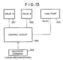
- A is a tube communicating-closing means 201 provided between the cap 2 (the end of suction inlet side) and the pressurizing roller acting area of the tube pump 203 (hereinafter called the suction side valve A).
- B is a communication-closing means 202 provided between the discharge ink tank 7 (the end on the discharge outlet side) and the pressurizing roller acting area of the tube pump (hereinafter called the discharge side valve B).
- 200 is the control circuit as CPU or specific control means for controlling these.
- the recovery mode a sequence in which usual recovery mode which performs suction by the tube pump alone, medium recovery mode which performs medium recovery strengthened in suction force by use of the suction side valve A, and strong recovery mode are performed as switched over. This is an application of the embodiment in Fig. 1.
- the recovery mode I in the flow chart n Fig 11 is prepared as the sub-routine for usual device main sequence, and actuates when the recovery command 204 is inputted manually or automatically.
- the rotational angle of the pressurizing roller in this embodiment is made an angle ⁇ 3 to the suction completion point with respect to the suction initiation point, and the angle smaller than this angle ⁇ 3 and greater than ⁇ 3/2 is made ⁇ 2. Therefore, the rotational angle at usual recovery mode and the rotational angle at the strong mode become the same in the present embodiment. Of course, although these may be not coincident, they are included within the technical content of the present invention.
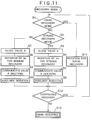
- step S1 In the recovery mode I, first it is judged in the step S1 whether the usual recovery mode is demanded or not. If the answer is YES here, rotation only of the angle ⁇ 3 for usual rotation is effected in the step S1. On the other hand, if it is NO, whether it is strong mode or not is judged in the step S2. If this judgement is YES, with the suction side valve A being closed (step S3), rotation of the pressurizing roller at the angle ⁇ 3 is executed (Step S4). Further, subsequent thereto, the suction side valve A after the execution is communicated (step S5).
- step S7 since it is medium recovery mode, the suction side valve A is closed (step S7), and the rotation of the pressurizing roller is executed a the angle ⁇ 2( ⁇ 2 ⁇ ⁇ 3) (step S8), and the suction side valve A is communicated as accompanied with the completion of rotation of the angle ⁇ 2.
- step S10 the pressurizing roller is further rotated, to effect auxiliary rotation before the pressurizing roller is released from the tube pressurized state
- the step S6 is different from the step S10, and may be made the rotation of the pressurizing roller to the stand-by position of the tube pump, but in this embodiment, further to the strong recovery mode, the pressurizing roller is subjected to auxiliary rotation by the angle ⁇ 3 of the usual recovery mode without use of the valve A. This is because the discharge ink after performing abruptly suction should be surely discharged.
- step S12 When either one of these steps S10, S6, S11 has been completed, presence of the continuous recovery command is judged in the step S12, and when it is present, the procedure returns to the step S1 to perform the sequence as described above. Although there may be no such step S12, there is the advantage that various complex recovery modes according to these can be practiced by the constitution as in the present embodiment.
- angles ⁇ 2, ⁇ 3 can be determined by rotational angle determination utilizing known encoder, or by various control means such as control of gear mesh number, etc., without explanation.
- judgement is performed in the present embodiment, when the device is provided with usual recovery key, medium recovery key, strong recovery key, by key input by the operator, the steps S11, S7 and S3 may be successively executed.
- Fig. 14 is a flow chart in place of the cam control of the embodiment in Fig. 7.
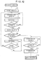
- Fig. 12 is a flow chart of the recovery mode II, and shows the maximum recovery mode which performs recovery by use of both the suction side valve A and the discharge side valve B.
- the suction side valve A is closed in the step P1, and subsequently the discharge side valve B is made under communicated state (step P2). Then, rotation of the pressurizing roller 5 is executed (step P3), and whether the desired rotational angle (the angle in the present embodiment) is completed or not is judged in the step P4, and steps P2 and P3 are performed before completion.
- the discharge side valve B is closed (step P5), and whether there is further recovery demand or not is judged in the step P6.
- the suction side valve A is communicated in the step P9 to perform suction.
- step P9 can perform equal action to the strong recovery mode of the flow chart shown in Fig. 11. Then, in the step 11, the discharge side valve B is communicated to have the ink absorbed onto the discharge ink side. After completion of this step, the main sequence is reached (step P12).
- step P6 when the answer is YES in the step P6, similarly as in Fig.. 7, the valve A is closed and the valve B communicated to further rotate the pressurizing roller by the angle ⁇ 3 to the suction initiation point 0 (step P7), and the suction actuation of judgement of the suction initiation is judged in the step P8 (step P3). Then, the above-described flow is continued.
- Fig. 13 has been as described above, but the above-described flow charts in Fig. 11, Fig. 12 may be also chosen to the control circuit 200 itself. Thus, various recovery conditions can be chosen by choosing the recovery modes I and II.
- Fig. 14 shows a more preferable constitution of the pressurizing roller 5 of the tube pump of the present invention.
- a lengthy roll is used for a plurality of tubes, but the present embodiment is characterized by provision of a pressurizing roller diplaceable single for each of the plural tubes.
- the guide roller 4 has four pressurizing rollers 5 (G, M, Y, Bk) for the four tubes 3 (C, M, Y, Bk), respectively at the sectionalized portions.
- the guide roller 4 has a pair of grooves 100C, 100M, 100Y, 100Bk for each tub 3 (C, M, Y, Bk) as a pair of grooves which guides the both side shafts 5A of the pressurizing roller so that the four pressurizing rollers 5 (C, M, Y, Bk) can be displaced independently.
- each of the pressurizing rollers 5 (C, M, Y, Bk) has a spring 101 (C, M, Y, Bk) between the shaft 4A of the guide roller 4 and each shaft 5A, and is urged in the direction pressing each tube 3.
- each independent pressurizing roller can be permitted to act on each tube, each tube pressure can be made constant, and suction can be surely effected even with lower pressure as compared with pressing a plurality of tubes with a lengthy roll.
- the load can be made smaller, and therefore the rotational load of the guide roller 4 becomes smaller, whereby there is the advantage that the driving motor can be made smaller.
- a pressurizing member in which the respective tubes are separated as shown in Fig. 14 as the pressurizing, namely closing means of a plurality of tubes, is a more preferable embodiment, and application of this technique to the suction side valve A or the discharge side valve B as described above is also preferable.
- the present invention by solving the drawbacks of the tube pump which is simple but cannot alter the suction force or the acting conditions, can provide a recovery device as desired, and can optimize also the constitution of the ink jet recording apparatus by use thereof.
- the present invention brings about excellent effects particularly in recording head, recording apparatus of the bubble jet system proposed by Canon K.K. among the ink jet recording system.
- This system is applicable to either one of the so called on-demand type and the continuous type, but particularly, in the case of the on-demand type, by applying at least one driving signal which gives rapid temperature elevation exceeding nucleus boiling corresponding to recording information to an electrothermal transducer arranged corresponding to the sheet or the liquid pathway in which liquid (ink) is held, heat energy is generated in the electrothermal transducer to effect film boiling at the heat-acting surface of the recording head, thereby consequently forming effectively bubbles within the liquid (ink) corresponding one by one to he driving signal.
- the driving signal is made pulse shape, growth and shrinkage of bubbles can be effected instantly and adequately, whereby discharging of the liquid (ink) particularly excellent in response can be more preferably accomplished.
- the pulse-shaped driving signal those as disclosed in U.S. Patents 4,463,359 and 4,345,262 are suitable.
- the constitution of the recording head in addition to the combined constitution of discharge port, liquid pathway, electrothermal transducer as described in the respective above-mentioned specifications (linear liquid pathway or right angle liquid pathway), the constitution by use of U.S. Patents 4,558,333 and 4,459,600 disclosing the constitution in which the heat-acting portion is arranged at the flexed region is also included in the present invention.
- the present invention is also effective, even when the constitution may be made as based on Japanese Laid-open Patent Application No. 59-123670 disclosing the constitution in which a common slit is made the discharging portion of the electrothermal transducer relative to a plurality of electrothermal transducers or Japanese Laid-open Patent Application No. 59-138461 disclosing the constitution in which opening absorbing the pressure wave of heat energy is made correspondent to the discharge portion.
- the recording head of the full-line type in having a length corresponding to the width of the maximum recording medium which can be recorded by the recording apparatus, either one of the constitution satisfying its length by a combination of a plurality of recording heads as disclosed in the above-described specifications or the constitution a single recording head integrally formed may be used, but the present invention can exhibit the above-described effects further effectively.
- the present invention is also effective when a recording head of the chip type freely interchangeable which enables electrical connection with the main device or feeding of ink from the main device by mounting on the main device, or a recording head of the cartridge type integrally provided on the recording head itself may be employed.
- recovery means for performing discharge separately from recording, which is also effective for performing stable recording.
- preliminary auxiliary means for performing discharge separately from recording, which is also effective for performing stable recording.
- the recording mode of the recording apparatus not only for the recording mode only of the primary color such as black, etc., but also the present invention is extremely effective for a device equipped with at least one of plural colors with different colors or full color by color mixing, which may be either in the form of a recording head constituted integrally or a plurality of recording heads.
- a recovery device is equipped with a tube pump which performs suction or pressurization by utilizing deformation of a tube applicable to a liquid jet recording apparatus.
- the recovery device comprises a mechanism which acts on a tube between the acting portion side acting on the discharge portion of the liquid jet recording head of the aforesaid tube pump and the aforesaid tube pump to effect communication and closing between the acting portion side and tube pump.
Abstract
A recovery device is equipped with a tube pump which performs suction or pressurization by utilizing deformation of a tube (3) applicable to a liquid jet recording apparatus. The recovery device comprises a mechanism which acts on a tube (3) between the acting portion side acting on the discharge portion of the liquid jet recording head of the aforesaid tube pump and the aforesaid tube pump to effect communication and closing between the acting portion side and tube pump.
Description
- This invention relates to an ink jet recording apparatus, more particularly to a tube pump constitution which maintains or recovers normal droplet discharge state of an ink jet head.
- In ink jet recording apparatuses of the prior art, for the purpose of maintaining normal droplet discharge state of the ink jet head or recovering to normal discharge state when clogging occurs at the discharge port, there has been employed means for arranging a pump for recovery and suction ink from the discharge port by the negative pressure of the pump. Also as the pump for recovery, there has been employed a tube pump which generates negative pressure by utilization of volume change within the tube. Such tube pump has the merits that the constitution is simple and small in scale, and also a pump can be formed at low cost.
- The tube pump of the prior art, which performs continuous suction while squeezing an extended tube by a pressurizing roller, can increase the suction amount per unit time with difficulty. For, if the cross-sectional area of the tube is attempted to be increased, enlargement of the tube or enlargement of the pressurizing roller is brought about, whereby not only the cost is increased, but also the increase of cross-sectional area is limited.
- In the tube pump mechanism of the prior art example used for recording head, during formation of the negative pressure, namely when the pressure becomes from zero to maximum pressure, the constitution is constantly communicated to the head side. For this reason, when a discharge port where clogging is generated by dust clogging or bubbles at the
discharge port 1A and a normal discharge port exist, ink may be discharged from the normal discharge port considerably before the pump becomes maximum pressure. In this case, when the pressurizing roller for tube pressurization reaches a point when maximum pressure can be generated, since the negative pressure accompanied with movement of the roller performs suction continuously therebefore, there has been loss of the negative pressure energy by ink flowout from the normal discharge port. Hence, the negative pressure on the discharge port where clogging to be recovered has occurred is reduced. Accordingly, it may be also conceivable to increase the acting area of the tube or the pressurizing roller for further enhancing the maximum pressure, but it will bring about enlargement of the tube pump mechanism to bring about increased cost. Also, the waste ink amount by suction recovery is increased, whereby there has been involved the problem of lowering in running cost of the ink jet head. Also, in recovery of non-discharging which occurs by generation of bubbles internally of the ink jet head, while rapid flowout rate of ink during suction is more advantageous for bubble removal, in the tube pump mechanism of the prior art, because the constitution can not give momentarily maximum pressure, the flowout rate of ink is lowered to have the drawback that efficiency of bubble removal is lowered. - The principal object of the present invention is to provide a novel tube pump mechanism which can solve the above-mentioned technical task and an ink jet recording apparatus having the same.
- Another object of the present invention is to provide a tube pump mechanism which can surely accomplish desired suction conditions in spite of a simple constitution without inviting enlargement of the device and an ink jet recording apparatus having the same.
- The present invention has been accomplished in vies of such technical tasks, and another object of the present invention is to provide an ink jet recording apparatus which can determine the magnitude of suction force corresponding to the clogging state of the discharge port, and can perform stable suction recovery even in the case of excessive clogging without enlargement of the device.
- Still another object of the present invention is to provide a recovery device equipped with a tube pump which performs suction or pressurization by utilizing deformation of a tube applicable to a liquid jet recording apparatus, comprising a mechanism which acts on a tube between the acting portion side acting on the discharge portion of the liquid jet recording head of the aforesaid tube pump and the aforesaid tube pump to effect communication and closing between said acting portion side and tube pump.
- Still another object of the present invention is to provide a liquid jet recording apparatus having a recovery device equipped with a tube pump which performs suction or pressurization through a member forming a hermetically closed state for a liquid jet recording head by utilizing deformation of a tube, comprising a mechanism which acts on a tube between the member forming a hermetically closed state for the discharge portion of the liquid jet recording head of the aforesaid tube pump and the aforesaid tube pump to effect communication and closing between said hermetically closed state forming member and tube pump.
- Still another object of the present invention is to provide a liquid jet recording apparatus having a recovery device equipped with a tube pump which performs suction or pressurization through a member forming a hermetically closed state for a liquid jet recording head by utilizing deformation of a tube, comprising a mechanism which acts on a tube between the member forming a hermetically closed state for the discharge portion of the liquid jet recording head of the aforesaid tube pump and the aforesaid tube pump to effect communication and closing between said hermetically closed state forming member and tube pump, thereby performing strong recovery mode and usual recovery mode.
- Still another object of the present invention is to provide an ink jet recording apparatus which performs recording by discharging an ink onto a recording medium, comprising an ink jet recording head for performing recording by discharging the ink onto the recording medium, a tube pump for suction of the ink from the above ink jet recording head, an opening and closing means provided on the opposite side of the above tube pump to the above recording head which performs opening and closing of the communication between said tube pump and the waste ink disposal side, a mechanism which acts on a tube between the acting portion side acting on the discharge portion of the liquid jet recording head of the aforesaid tube pump and the aforesaid tube pump to effect communication and closing between said acting portion side and tube pump, and a control means which actuates the aforesaid tube pump for a predetermined term under the tube closed state of both said mechanism and said opening and closing means and thereafter makes said mechanism under tube communicated state.
- According to the present invention, by having a mechanism for communication and closing between the cap and the tube by squeezing the tube at the portion connecting the cap forming the hermetically closed system in the ink jet head with the tube pump, maximum pressure generated at the tube pump can be momentarily given to enhance reliability of recovery. Also, lowering of running cost can be realized by lowering the amount of waste ink during suction.
- Further, by moving the pressurization mechanism of the above-mentioned tube in association with the pumping actuation of the tube pump, the manner of application of negative pressure on the head surface can be changed or the time of the time when negative pressure is applied on the head surface (holding time) can be changed according to a simple mechanical constitution.
- The present invention provided with a means for opening and closing the communication of the tube between the tube pump and the waste ink disposal side has made the magnitude of the negative pressure by varying the number of press-down of the tube by a pressurization roller, and therefore the magnitude of the suction force could be set corresponding to the clogging state of the discharge port.
-
- Fig. 1 is a front view showing an enbodiment of the present invention;
- Fig. 2 is a plan view of the embodiment in Fig. 1;
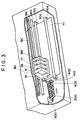
- Fig. 3 is a perspective view of he pertinent portion of a color ink jet printer to which the present invention is applied;
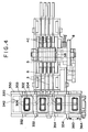
- Fig. 4 is an upper view of the constitution in which a tube pump is combined with the cap unit in Fig. 3;
- Fig. 5 and Fig. 6 are plan views of another embodiment of the present invention;
- Fig. 7 is a front view of another embodiment of the present invention;
- Fig. 8 is a plan view of Fig. 7;
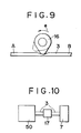
- Fig. 9 is a side view showing schematically another structural example of the tube communication opening and closing means in Fig. 7;
- Fig. 10 is a side view showing schematically still another structural example of the tube communication opening and closing means in Fig. 7;
- Fig. 11 is a flow chart of an embodiment resembling the embodiment of the present invention in Fig. 1;
- Fig. 12 is a flow chart of an embodiment resembling the embodiment of the present invention in Fig. 7;
- Fig. 13 is a block diagram to be utilized in the embodiments in Fig. 11 and Fig. 12;
- Fig. 14 is an illustration showing a modification example of the pertinent portion of the tube pump of the present invention.
- The present invention is described below by referring to embodiments, by which the present invention is not limited but is also inclusive of the invention as the single recovery device.
- First, by use of Fig. 3, Fig. 4, the cap, blade constitutions for a color recording head (C: cyan head, M: magenta head, Y: yellow head, BK: black head) are to be described.
- This embodiment can be applied to a recording apparatus such as a printer, a copying machine, a facsimile, etc., and is constituted so as to record an image comprising a dot pattern on a recording medium such as paper or plastic thin plate, based on an image information.
- The constitution of the recording apparatus in Fig. 3 comprises an ink jet recording means 80 of the serial type mounted on a
recording carriage 19, so that arecording sheet 111 may be conveyed by a conveying means to the position of said recording means 80. - The recording means records ink images onto the
recording sheet 111, and in this embodiment, the ink jet recording system is employed. - The ink
jet recording head 1 is equipped with a liquid discharge port for jet discharging the ink liquid for recording as flying droplets, a liquid pathway communicated to said discharge port, and a discharge energy generation means provided at a part of the liquid pathway for giving discharge energy for permitting the ink liquid to fly. The above-mentioned discharge energy means is driven corresponding to image signals, thereby discharging ink droplets to record images. - As the above-mentioned discharge energy generation means, for example, there may be included the method by use of a pressure energy generation means such as electromechanical transducer such as piezoelectric device, etc., the method by use of an electromagnetic energy generation means which generates flying droplets by permitting electromagnetic wave such as laser, etc. to be absorbed by ink by irradiation, or the method by use of a heat energy generation means such as electrothermal transducer, etc. Among them, the system by use of a heat energy generation means is preferable, because discharge ports can be arranged at high density, and also the recording head can be made compact.
- The four
recording heads - The
recording carriage 19 moves the above recording means 80 in the main scanning direction in reciprocal fashion, and is mounted slidably on themain scanning rail 19a as shown in Fig. 3. - In the vicinity of the both ends of the above
main scanning rail 19a are mounted a driving pulley and a driven pulley (not shown), and a timing bell 19c provided by spanning between the both pulleys is connected to the above recordingcarriage 19. Further, to the above driving pulley is joined a recording carriage motor (not shown). - Therefore, when the above carriage motor rotates normally and reversedly, the
recording carriage 19 is guided by the rail 9a to move in the main scanning direction in reciprocal fashion. - The recording sheet housed within a known cassette is fed as separated sheet by sheet by the pick-up roller and the separating nail provided at the tip of the cassette, and is constituted so that it may be conveyed by conveying
roller pair recording head 1. - Such conveying actuation corresponds to the recording width by the above recording means 8 (8.128 mm in this embodiment), and the sheet is conveyed intermittently at 8.128 mm pitch as synchronized with the recording actuation during recording.
- The
cap unit 300 has caps corresponding respectively to therecording heads 1, and is slidable in the right and left directions in the drawing as accompanied with the movement of therecording carriage 19 and also vertically elevatable corresponding to the cap position and the non-cap position. When therecording carriage 19 is at the home position, it is bonded to therecording head portion 1A to cap it. - 401 is a first blade for cleaning the discharge port area, two 402's are each second blade as the member for wiping the cap contact surface area of the head, and 403 is a blade cleaner comprising, for example, an absorbing material for cleaning of the
first blade 401. In this embodiment, thefirst blade 401 is held by the blade elevating mechanism driven by the movement of therecording carriage 9, whereby thefirst blade 401 is displaceable to the position of the discharge port forming surface of the recording head 8b where it is protruded (ascended) so as to wipe the surface of the exposed orifice plate 103, and to the position retreated (descended) so as not to interfere therewith. - As shown in Fig. 4, the
cap unit 300 hascaps 302 closely contacted around each of the four recording heads 1 (four as the total),holders 303 supporting these, absorbing materials for receiving ink during black discharge treatment and suction treatment, a suction tube for suction of the received ink, and further atube 3 communicated to apump unit 500. - 332 and 334 are pins provided as projected from the
cap holder 330, and respectively engaged with thecam grooves cap holder 330 provided at the fixed recovery system base 340 in the right and left direction and the vertical direction as described above. Between onepin 334 of thecap holder 330 and the stand-upportion 364 of therecovery system base 360 is spanned aspring 360, whereby an urging force is given to thecap holder 330 so that it may be held at the position shown in the same Figure, namely the right end position and the descending position. The position opposed to therecording head 1 mounted on therecording carriage 19 with respect to the cap holder or thecap unit 300 at this position is the start position (SP) of therecording carriage 19 during one scan of recording processing. - 342 is the engaging portion stood up from the cap
holder cap holder 330 and engaged with therecording carriage 19 at the position on the left side of the start position. When therecording carriage 19 moves left from the start position, thecap holder 330 moves from the cap holder by the engagedportion 342 as accompanied therewith against the urging force of thespring 360. At this time, thecap holder 330 is guided along thecap grooves pins cap 302 is closely contacted with surroundings of therecording head 1 and thedischarge port 1A, thereby applying capping. The position of therecording carriage 19 when this capping is applied is made the home position. - Fig. 1 and Fig. 2 show embodiments of the present invention, Fig. 1 being a front view of the present embodiment and Fig. 2 a plant view of the present embodiment. This embodiment is an embodiment of a full color ink jet recording apparatus of yellow, cyan, magenta, black, and the modes of these heads are not limited to the present embodiment, but can be also applied to one head monochromatic recording.
- In the following, the constitution of the present embodiment is described by use of a suction recovery actuation.
- First, the opening of the
cap 2 is permitted to contact theink jet head 1 at the home position as described above to form a hermetically closed form at thedischarge port 1A. To the other opening of thecap 2 is connected atube 3, which is further connected to the tube pump side. Next, the constitution of the pump is described. Theshaft portions pressure roller 5 pressurizing the tube are supported rotatably on theguide roller 4. Theshaft portions guide roller 4 are supported rotatably on theside face portions pump base 6. Also, arc-shaped groove concentric to the shaft of theguide roller 4 is formed on thepump base 6. Further, at theshaft portion 4B of the guide roller are fixed adriving gear 14, and at 4A acam 8, at a certain relative positional relationship. Next, the mechanism of the pressurizing portion of the tube is described. Theshaft portion 9A of the pressurizingroller 9 is supported on the pressurizingside plate 10. The pressurizingside plate 10 is pressurized in the arrowhead direction d by a spring hung between theshaft portion 9A of the pressurizingroller 9 and theshaft 12 fixed on thepump base 6 with therotational shaft 11 fixed at thepump base 6 as the rotational center. - The
tube 3 is fixed on thepump base 6 at thegroove portions pump base 6. At theguide roller 4, each tube is guided at therib 4C. Further, the downstream portion of thetube 3 is connected to thedisposal member 7 of waste ink. - In the above-described constitution, when the
driving gear 14 is driven by a driving source, theguide roller 4 rotates in the arrowhead direction a, whereby the pressurizingroller 5 on theguide roller 4 contacts and pressurized thetube 3 at the portion X (shown by ...5'), thereby squeezing thetube 3 until the space internally of the pressed tube becomes zero. At this time, theprojection 8A of thecam 8 is located at the non-contacted position (shown by ...8A') with the pressurizing side plate. Under this state, the pressurizingroller 9 pressurizes thetube 3 pressurized in the arrowhead direction d by thespring 13, thereby closing communication between the cap side and the pump side (shown by ...9'). When the guide roller further rotates in the arrowhead direction a, theguide roller 5 rotates as driven in the arrowhead direction b under the state with thetube 3 being squeezed. When the pressurizingroller 5 comes to the point Y where maximum pressure is formed, theprojection 8A formed on thecam 8 contacts thelever 10A of the pressurizingside plate 10 to displace the pressurizingroller 9 toward the arrowhead direction c, thereby making the cap portion and the pump portion under communicated state. Hence, to thedischarge port 1, the negative pressure of maximum formed at the tube pump is given momentarily. - In the present embodiment, the constitution of giving momentarily the maximum pressure generated at the tube pump has been described, but the following constitution becomes possible by changing the relative relationship between the pressurizing
roller 5 and thecam 8 or the shape of thecam 8A. - First, the constitution of changing the magnitude of the negative pressure given to the head surface by changing the relative relationship between the pressurizing
roller 5 and thecam 8A is described by referring to Fig. 5. Concerning the constitutions of parts and basic actuations, the constitutions are the same as in Fig. 1, Fig. 2, with only the relative positional relationship between the pressurizingroller 5 and thecam 8A being different. In Fig. 5, when thedriving gear 14 is driven from a driving source not shown, theguide roller 4 rotates in the arrowhead direction a, whereby the pressurizingroller 5 on theguide roller 4 contacts and presses thetube 3 at the portion X in Fig. 1 (shown by ...5') to squeeze thetube 3 until the space internally of the tube becomes zero. At this time, theprojection 8A is located at the non-contacted position (shown by ...8A') with the pressurizing side plate. Under this state, the pressurizingroller 9 pressurizes thetube 3 pressurized in the arrowhead direction d by thespring 13, thereby closing communication with the cap side (shown by ...9'). When theguide roller 4 further rotates in the arrowhead direction a, theguide roller 5 rotates as driven in the arrowhead direction d under the state with thetube 3 being squeezed. When the pressurizing roller comes to the point Y', theprojection 8A on thecam 8 contacts thelever 10A of the pressurizingside plate 10 to displace the pressurizingroller 9 toward the arrowhead direction c, thereby making the cap portion and the pump portion under communicated state. Hence, to thedischarge port 1, the negative pressure by the volume change within the tube between the moved distance of the pressurizing roller 5 (X → Y) while squeezing thetube 3 tube pump is given momentarily. Thus, by changing the relative positions of the pressurizingroller 5 and thecam 8A, the magnitude of the negative pressure given to the head surface can be changed. Shortly speaking, when the pressurizingroller 9 moved by thecam 8A in the arrowhead direction c to make the cap side and the pump side under communicated state, the negative pressure becomes smaller if the position of the pressurizingroller 5 approaches the X side, while it becomes larger if the position approaches the Y side. - Next, the constitution of changing the time of giving a negative pressure to the head surface by changing the shape of the
cam 8A is described. Concerning the constitutions fo the parts and the basic actuations, the constitutions are the same as in Fig. 1, Fig. 2, with only the shape of thecam 8A being different. In Fig. 6, thecam 8A is larger as compared in Fig. 1, and the pressurizingroller 9 moves by thecam 8A toward arrowhead direction c, whereby the time when the cap side is communicated with the pump side becomes longer. Shortly speaking, by changing the shape of thecam 8A, the time of giving a negative pressure to the head surface (retention time) can be changed. - Further, by forming a plurality of projections of 8A on the
cam 8, it also becomes to have a constitution which gives the negative pressure divided in several times by ordinary one rotational actuation of tube pump. - Thus, by changing the relative relationship between the pressurizing
roller 5 and thecam 8A or the shape of thecam 8A, the manner in which negative pressure is given to the head surface or the time of giving negative pressure to the head surface (retention time) can be changed. Hence, by devising these constitutions, reliability and efficiency of suction recovery can be increased. - In the above embodiment of the preset invention, a preferable constitution which moves in associated fashion with the tube pump is shown, but in the present invention, a mechanism which accomplishes closing and communication of the above tube by a driving force from another driving source satisfying the above timing relationship without association with the tube pump is also included. In the above embodiment, one which is recovered by suction is shown, but also a recovery device which is recovered by pressurization can be also utilized in the present invention. This case can be accomplished by performing closing of the above tube and the opening timing of the mechanism accomplishing communication after formation of the tube portion pressurizied by the reverse rotation of the above tube pump. As the strong recovery mode, the constitution of the present invention as described above may be employed, and in a device in which recovery without use of the tube opening and closing mechanism of the present invention as the simple recovery (for example, the constitution which makes the cam non-actuating as shown in Fig. 1), the constitution having such simple recovery mode is also included in the present invention.
- As described above, by having a mechanism of communication and closing acting on the tube at the portion connecting between the member acting on an ink jet head and the tube pump, maximum pressure generated at the tube pump can be momentarily give to an objective member such as liquid jet recording head to enhance reliability of recovery. Also, by lowering the amount of waste ink during suction, lowering in running cost can be realized. Further, by moving the pressurizing mechanism of the above tube in associated fashion with the pumping actuation of the tube pump, there is the effect of realizing change of the manner of giving the negative pressure to the head surface or the change of time of the negative pressure applied on the head surface (retention time) by a simple mechanical constitution.
- Fig. 7 to Fig. 10 show embodiments of the tube pump which can generate greater negative pressure than the previous embodiment. These embodiments have constitutions similar to the previous constitutional embodiment, and therefore description is made by use of the same numerals for the similar constitutions.
- First, the
valve mechanism 800 corresponding to the previous tube closing constitution is described. Between thecap 2 of thetube 3 and thetube pump 50 is arranged avalve 800 which opens and closes (communicates and shuts down) communication between said cap and said pump. - The
valve 800 can be made a structure which opens and closes communication of saidtube 3 by squeezing the tube 3 (the constitution in Fig. 1, etc.), or any other appropriate structure. - During the actuation of the tube pump as described below, the
above valve 800 is closed, and thecap 2 and thepump 50 are under closed state therebetween. - For this reason, a negative pressure is generated by volume change within the
tube 3 squeezed by the pressurizingroller 5 between thevalve 800 and thetube pump 50. - When the
valve 800 is opened under the state where the negative pressure is generated to make thecap 2 and thetube pump 50 communicated to each other, the negative pressure generated at the pump portion acts on thedischarge port 1A, whereby ink suction actuation from the discharge port is effected. - Fig. 7 is a longitudinal sectional view showing schematically the pertinent portion of an embodiment of the ink jet recording apparatus according to the present invention, and Fig. 8 is a plan view of Fig. 7.
- In Fig. 7 and Fig. 8, the opening of the
cap 2 is permitted to contact the inkjet recording head 1 at the non-recording position to seal thedischarge port 1A, thereby forming a hermetically closed space therebetween. The difference from the previous embodiments is primarily described. This embodiment is characterized by having, in addition to thevalve mechanism 800, an opening and closing means which opens and closes communication of thetube 3 between thetube pump 50 and the wasteink disposal side 7. This structure is now described. - On the
shaft 11 fixed on thepump base 6 is axially supported abracket 10 freely rotatably, and on saidbracket 10 is axially supported a pressurizingroller 9 through theshaft 9A. - The
above bracket 10 is urged toward the direction to squeeze thetube 3 by the above pressurizing roller (the arrowhead direction d in Fig. 7) by aspring 13 hung between theabove shaft 9A on said bracket and theshaft 12 fixed on thepump base 6. - In the embodiment shown, the
above tube 3 and the pressurizingroller 5, etc. are provided each in number of 4 corresponding to the number of the recording heads 1, and eachtube 3 is fixed on saidpump base 6 ast thegrooves pump base 6. - At the
guide roller 4, theabove tubes 3 are guided one by one by theribs 4C arranged at predetermined intervals. - The end on the downstream side of each tube 3 (the end opposite to the cap 2) is connected to the waste
ink disposal member 7 as described above. - In the above-described constitution, when the
driving gear 14 is driven by a driving source, theguide roller 4 rotates in the arrowhead direction a, whereby the pressurizingroller 5 on saidguide roller 4 contacts thetube 3 at the position X in Fig. 7 and squeezes saidtube 3 until there is no innerside space within saidtube 3. - At this time, the
tip 15B of the projection (the portion with larger outer diameter) 15A of thecam 15 of theguide roller 15 contacts theprojection 10A of thebracket 10 to push saidbracket 10 toward the anticlockwise direction with respect to theshaft 11, thereby displacing the pressurizingroller 9 in the arrowhead direction c to make thetube pump 50 and the wasteink disposal member 7 communicated to each other. - When the
guide roller 4 further rotates in the arrowhead direction a, the pressurizingroller 5 moves to the position Y shown by the two-dot chain line while rotating by itself toward the arrowhead direction b under the state squeezing thetube 3. - During this actuation, since the
projection 15A of thecam 15 contacts constantly theprojection 10A of thebracket 10, thetube pump 50 and the wasteink disposal member 7 are maintained under communicated state. - Shortly speaking, during the period when the pressurizing
roller 5 moves from the position X to the position Y, the air within thetube 3 during that period is discharged to the wasteink disposal member 7 side. - And, when the pressurizing
roller 5 comes to the position Y, namely when thecam 15 together with the guide roller come to the position shown by the two-dot chain line, therear end 15C of theprojection 15A of thecam 15 departs from theprojection 10A of thebracket 10. - Under this state, the
bracket 10 and the pressurizingroller 9 are urged by thespring 13 toward the clockwise direction with theshaft 11 as the center, whereby thetube 3 is squeezed by said pressurizing roller pressed in the arrowhead direction d to effect shut-down between thetube pump 50 and the wasteink disposal member 7. - When the
guide roller 4 further rotates in the arrowhead direction a and the pressurizingroller 5 comes to the position Z shown by the two-dot chain line, said pressurizingroller 5 departs from thetube 3 to release squeezing of thetube 3 by said pressurizingroller 5. - Under this state, the
above valve 8 and theabove pressurizing roller 9 become communicated therebetween. - As a consequence, the pressurizing
roller 5 moves from the position X to the position Y while squeezing thetube 3 to discharge the air within thetube 3 during that period toward the wasteink disposal member 7 side, whereby the volume of the air within saidtube 3 is reduced to make the space between thevalve 8 and the pressurizingroller 9 under reduced pressure (negative pressure) state. - When the
guide roller 4 further rotates toward the arrowhead direction a, thepressure roller 5 returns to the original position (the position X). - And, the same actuation is repeated, if necessary.
- At this time, the difference from the first actuation is that the pressure within the
tube 3 is already under reduced (negative pressure) state. - Therefore, by repeating the above actuation, the extent of reduced pressure (negative pressure) between the
valve 8 and the pressurizingroller 9 becomes greater by increased discharge of the air within thetube 3 toward theink disposal member 7 side as the number of rotation of theguide roller 4 is increased. - Shortly speaking, the negative pressure within the
tube 3 becomes greater than the rigidity of saidtube 3, whereby no space is created within thetube 3. - Such reduced pressure can be effected to the limiting pressure (which changed depending on the material, the thickness, etc. of the tube 3) of the
tube 3. - When the
tube 3 is internally reduced to a desired negative pressure, by opening of thevalve 800, said negative pressure is permitted to act on the discharge port of therecording head 1 to effect ink suction actuation from the discharge port. - According to the embodiment as described above, the magnitude of the negative pressure of the
tube pump 50 can be controlled by the rotational number (number of rotations) of theguide roller 4, and by control of opening and closing of thevalve 800, it has become possible to give a negative pressure freely set on thetube pump 50 side to thedischarge port 1A of therecording head 1. - In other words, according to the embodiment as described above, since an opening and closing means for opening and closing communication between the
tube pump 50 and the waste ink disposal side at the downstream side thereof is provided, by varying the rotational number of the guide roller 4 (squeezing number of thetube 3 by the pressurizing roller 5), the magnitude of the suction force can be made variable, whereby it has become possible to set freely the magnitude of the suction force freely corresponding to the clogging state at the discharge port. - For this reason, efficient suction recovery could be done and running cost could be reduced without superfluous consumption of ink.
- Also, without enlargement of the device, the maximum Suction force could be set to the limiting negative pressure which can be generated by the
tube pump 50. - Accordingly, even if there may occur excessive clogging at the
discharge port 1A by such factors as dust clogging, bubble generation in ink, ink attachment, etc., stable suction recovery could be done to enhance reliability of the ink jet head. - Further, by constituting the opening and closing means which opens and closes communication between the
tube pump 50 and the waste ink disposal side of a tube squeezing means, and also associating the moving force for the tube squeezing actuation with the pump actuation as the constitution obtained from the driving source of thetube pump 50, the effects as mentioned above could be accomplished with a mechanical constitution which is simple and low in cost. - Fig. 9 is a schematic view showing the pertinent portion of another embodiment of the opening and closing means which opens and closes communication between the
tube pump 50 and the wasteink disposal side 7. - In the embodiment as described above, as the opening and closing means, a means of squeezing the
tube 3 by spring pressurization is employed, but when the squeezing actuation of thetube 3 is to be utilized, as shown in Fig. 9, it is also possible to employ the constitution which opens and closes communication between the position A and the position B by squeezing thetube 3 by rotation of theeccentric cam 16 in the arrowhead direction e. - Fig. 10 is a schematic view showing the pertinent portion of still another embodiment of the opening and closing means which opens and closes communication between the
tube pump 50 and the waste ink disposal side, and as shown in the Figure, it is also possible to employ a constitution in which avalve 17 which opens and closes communication of thetube 3 between thetube pump 50 and the wasteink disposal side 7. - Each of the embodiments in Fig. 1 through Fig. 10 as described above is a valve mechanism control by utilizing a cam as the mechanism which communicates or closes the ink pathway between the acting region of the tube pump and either of the cap or the discharge ink tank, but the present invention may also include valve mechanisms which are electically controlled corresponding to rotation of the pressurizing
roller 5. - Embodiments of other control means are described by use of Fig. 11 through Fig. 14.
- As is common to these Figures, particularly as shown in the block diagram in Fig. 14, A is a tube communicating-closing means 201 provided between the cap 2 (the end of suction inlet side) and the pressurizing roller acting area of the tube pump 203 (hereinafter called the suction side valve A). B is a communication-closing means 202 provided between the discharge ink tank 7 (the end on the discharge outlet side) and the pressurizing roller acting area of the tube pump (hereinafter called the discharge side valve B). 200 is the control circuit as CPU or specific control means for controlling these.
- In the flow chart in Fig. 11, there is shown as the recovery mode a sequence in which usual recovery mode which performs suction by the tube pump alone, medium recovery mode which performs medium recovery strengthened in suction force by use of the suction side valve A, and strong recovery mode are performed as switched over. This is an application of the embodiment in Fig. 1.
- The recovery mode I in the flow chart n Fig 11 is prepared as the sub-routine for usual device main sequence, and actuates when the
recovery command 204 is inputted manually or automatically. - The rotational angle of the pressurizing roller in this embodiment, as shown in Fig. 14, is made an angle ϑ₃ to the suction completion point with respect to the suction initiation point, and the angle smaller than this angle ϑ₃ and greater than ϑ₃/2 is made ϑ₂. Therefore, the rotational angle at usual recovery mode and the rotational angle at the strong mode become the same in the present embodiment. Of course, although these may be not coincident, they are included within the technical content of the present invention.
- In the recovery mode I, first it is judged in the step S1 whether the usual recovery mode is demanded or not. If the answer is YES here, rotation only of the angle ϑ₃ for usual rotation is effected in the step S1. On the other hand, if it is NO, whether it is strong mode or not is judged in the step S2. If this judgement is YES, with the suction side valve A being closed (step S3), rotation of the pressurizing roller at the angle ϑ₃ is executed (Step S4). Further, subsequent thereto, the suction side valve A after the execution is communicated (step S5). On the contrary, if the judgement is NO, since it is medium recovery mode, the suction side valve A is closed (step S7), and the rotation of the pressurizing roller is executed a the angle ϑ₂(ϑ₂ < ϑ₃) (step S8), and the suction side valve A is communicated as accompanied with the completion of rotation of the angle ϑ₂. In the medium recovery mode, the pressurizing roller is further rotated, to effect auxiliary rotation before the pressurizing roller is released from the tube pressurized state (step S10). The step S6 is different from the step S10, and may be made the rotation of the pressurizing roller to the stand-by position of the tube pump, but in this embodiment, further to the strong recovery mode, the pressurizing roller is subjected to auxiliary rotation by the angle ϑ₃ of the usual recovery mode without use of the valve A. This is because the discharge ink after performing abruptly suction should be surely discharged.
- When either one of these steps S10, S6, S11 has been completed, presence of the continuous recovery command is judged in the step S12, and when it is present, the procedure returns to the step S1 to perform the sequence as described above. Although there may be no such step S12, there is the advantage that various complex recovery modes according to these can be practiced by the constitution as in the present embodiment.
- And when there the judgement in the step S12 is absent, the procedure returns to the main sequence S13 to complete the present sub-routine.
- Whereas, the angles ϑ₂, ϑ₃ can be determined by rotational angle determination utilizing known encoder, or by various control means such as control of gear mesh number, etc., without explanation. Although judgement is performed in the present embodiment, when the device is provided with usual recovery key, medium recovery key, strong recovery key, by key input by the operator, the steps S11, S7 and S3 may be successively executed.
- Fig. 14 is a flow chart in place of the cam control of the embodiment in Fig. 7. Fig. 12 is a flow chart of the recovery mode II, and shows the maximum recovery mode which performs recovery by use of both the suction side valve A and the discharge side valve B.
- When the recovery mode II is designated, the suction side valve A is closed in the step P1, and subsequently the discharge side valve B is made under communicated state (step P2). Then, rotation of the pressurizing
roller 5 is executed (step P3), and whether the desired rotational angle (the angle in the present embodiment) is completed or not is judged in the step P4, and steps P2 and P3 are performed before completion. When the answer in the step P4 is Yes, the discharge side valve B is closed (step P5), and whether there is further recovery demand or not is judged in the step P6. When the judgement here is NO, the suction side valve A is communicated in the step P9 to perform suction. Since suction corresponding to the negative pressure within the tube is effected abruptly, more excellent suction amount than by usual recovery can be obtained. This step P9 can perform equal action to the strong recovery mode of the flow chart shown in Fig. 11. Then, in thestep 11, the discharge side valve B is communicated to have the ink absorbed onto the discharge ink side. After completion of this step, the main sequence is reached (step P12). - Whereas, when the answer is YES in the step P6, similarly as in Fig.. 7, the valve A is closed and the valve B communicated to further rotate the pressurizing roller by the angle ϑ₃ to the suction initiation point 0 (step P7), and the suction actuation of judgement of the suction initiation is judged in the step P8 (step P3). Then, the above-described flow is continued.
- Therefore, it could be understood that the present invention can be also practiced by timing control without use of a special cam constitution.
- The block diagram in Fig. 13 has been as described above, but the above-described flow charts in Fig. 11, Fig. 12 may be also chosen to the
control circuit 200 itself. Thus, various recovery conditions can be chosen by choosing the recovery modes I and II. - Fig. 14 shows a more preferable constitution of the pressurizing
roller 5 of the tube pump of the present invention. In the previous embodiment, a lengthy roll is used for a plurality of tubes, but the present embodiment is characterized by provision of a pressurizing roller diplaceable single for each of the plural tubes. Theguide roller 4 has four pressurizing rollers 5 (G, M, Y, Bk) for the four tubes 3 (C, M, Y, Bk), respectively at the sectionalized portions. Theguide roller 4 has a pair of grooves 100C, 100M, 100Y, 100Bk for each tub 3 (C, M, Y, Bk) as a pair of grooves which guides the bothside shafts 5A of the pressurizing roller so that the four pressurizing rollers 5 (C, M, Y, Bk) can be displaced independently. And, each of the pressurizing rollers 5 (C, M, Y, Bk) has a spring 101 (C, M, Y, Bk) between theshaft 4A of theguide roller 4 and eachshaft 5A, and is urged in the direction pressing eachtube 3. - According to such constitution, since each independent pressurizing roller can be permitted to act on each tube, each tube pressure can be made constant, and suction can be surely effected even with lower pressure as compared with pressing a plurality of tubes with a lengthy roll. Particularly, the load can be made smaller, and therefore the rotational load of the
guide roller 4 becomes smaller, whereby there is the advantage that the driving motor can be made smaller. - Thus, use of a pressurizing member in which the respective tubes are separated as shown in Fig. 14 as the pressurizing, namely closing means of a plurality of tubes, is a more preferable embodiment, and application of this technique to the suction side valve A or the discharge side valve B as described above is also preferable.
- As described above, the present invention, by solving the drawbacks of the tube pump which is simple but cannot alter the suction force or the acting conditions, can provide a recovery device as desired, and can optimize also the constitution of the ink jet recording apparatus by use thereof.
- The present invention brings about excellent effects particularly in recording head, recording apparatus of the bubble jet system proposed by Canon K.K. among the ink jet recording system.
- Concerning its representative constitution and principle, for example, those by use of the basic principle disclosed in U.S. Patents 4,723,129 and 4,740,796 are preferred. This system is applicable to either one of the so called on-demand type and the continuous type, but particularly, in the case of the on-demand type, by applying at least one driving signal which gives rapid temperature elevation exceeding nucleus boiling corresponding to recording information to an electrothermal transducer arranged corresponding to the sheet or the liquid pathway in which liquid (ink) is held, heat energy is generated in the electrothermal transducer to effect film boiling at the heat-acting surface of the recording head, thereby consequently forming effectively bubbles within the liquid (ink) corresponding one by one to he driving signal. By discharging the liquid (ink) through the opening for discharge by growth, shrinkage of the bubble, at least one droplet is formed. If the driving signal is made pulse shape, growth and shrinkage of bubbles can be effected instantly and adequately, whereby discharging of the liquid (ink) particularly excellent in response can be more preferably accomplished. As the pulse-shaped driving signal, those as disclosed in U.S. Patents 4,463,359 and 4,345,262 are suitable. By employment of the conditions described in the above U.S. Patent 4,313,124 concerning the invention of the temperature elevation rate of the heat-acting surface, further excellent recording can be performed.
- As the constitution of the recording head, in addition to the combined constitution of discharge port, liquid pathway, electrothermal transducer as described in the respective above-mentioned specifications (linear liquid pathway or right angle liquid pathway), the constitution by use of U.S. Patents 4,558,333 and 4,459,600 disclosing the constitution in which the heat-acting portion is arranged at the flexed region is also included in the present invention. In addition, the present invention is also effective, even when the constitution may be made as based on Japanese Laid-open Patent Application No. 59-123670 disclosing the constitution in which a common slit is made the discharging portion of the electrothermal transducer relative to a plurality of electrothermal transducers or Japanese Laid-open Patent Application No. 59-138461 disclosing the constitution in which opening absorbing the pressure wave of heat energy is made correspondent to the discharge portion.
- Further, as the recording head of the full-line type in having a length corresponding to the width of the maximum recording medium which can be recorded by the recording apparatus, either one of the constitution satisfying its length by a combination of a plurality of recording heads as disclosed in the above-described specifications or the constitution a single recording head integrally formed may be used, but the present invention can exhibit the above-described effects further effectively.
- In addition, the present invention is also effective when a recording head of the chip type freely interchangeable which enables electrical connection with the main device or feeding of ink from the main device by mounting on the main device, or a recording head of the cartridge type integrally provided on the recording head itself may be employed.
- Also, addition of recovery means, preliminary auxiliary means, etc. to the recording head provided as the constitution of the recording apparatus of the present invention is preferable, because the effects of the present invention can be further stabilized. Specific examples of these may include capping means, cleaning means, pressurizing or suction means, electrothermal transducer or heating element separate from this or preliminary heating means according to combination of these, preliminary discharge mode for performing discharge separately from recording, which is also effective for performing stable recording.
- Further, as the recording mode of the recording apparatus, not only for the recording mode only of the primary color such as black, etc., but also the present invention is extremely effective for a device equipped with at least one of plural colors with different colors or full color by color mixing, which may be either in the form of a recording head constituted integrally or a plurality of recording heads.
- A recovery device is equipped with a tube pump which performs suction or pressurization by utilizing deformation of a tube applicable to a liquid jet recording apparatus. The recovery device comprises a mechanism which acts on a tube between the acting portion side acting on the discharge portion of the liquid jet recording head of the aforesaid tube pump and the aforesaid tube pump to effect communication and closing between the acting portion side and tube pump.
Claims (8)
- A recovery device equipped with a tube pump (4, 4A, 4B, 5, 5A, 5B, 6, 6A, 6B, 50) which performs suction or pressurization by utilizing deformation of a tube (3), said recovery device being applicable to a liquid jet recording apparatus,
characterized by
a mechanism (8, 8A, 9, 9A, 10, 10A, 11, 800) which acts on said tube (3) between an acting portion side of said tube (3) acting on a discharge portion (1A) of a liquid jet recording head (1) of said liquid jet recording apparatus and said tube pump (4, 4A, 4B, 5, 5A, 5B, 6, 6A, 6B, 50) to effect communication and closing between said acting portion and said tube pump (4, 4A, 4B, 5, 5A, 5B, 6, 6A, 6B, 50) and opening and closing means (8', 8A', 9', 9A', 10', 10A', 11') provided on the opposite side of said mechanism (8, 8A, 9, 9A, 10, 10A, 11, 800) with respect to said tube pump (4, 4A, 4B, 5, 5A, 5B, 6, 6A, 6B, 50), said opening and closing means (8', 8A', 9', 9A', 10', 10A', 11') performing opening and closing of the communication between said tube pump (4, 4A, 4B, 5, 5A, 5B, 6, 6A, 6B, 50) and a waste ink disposal (7) and
control means which actuate said tube pump (4, 4A, 4B, 5, 5A, 5B, 6, 6A, 6B, 50) for a predetermined time when said tube (3) is closed by said opening and closing means (8', 8A', 9', 9A', 10', 10A', 11') and by said mechanism (8, 8A, 9, 9A, 10, 10A, 11, 800) and thereafter opens said mechanism (8, 8A, 9, 9A, 10, 10A, 11, 800). - A liquid jet recording apparatus having a recovery device equipped with a tube pump (4, 4A, 4B, 5, 5A, 5B, 6, 6A, 6B, 50) which performs suction or pressurization through a member (2, 300) forming a hermetically closed state for a liquid jet recording head (1) by utilizing deformation of a tube (3),
characterized by
a mechanism (8, 8A, 9, 9A, 10, 10A, 11, 800) which acts on said tube (3) between said member (2, 300) forming said hermetically closed state for a discharge portion (1A) of a liquid jet recording head (1) and said tube pump (4, 4A, 4B, 5, 5A, 5B, 6, 6A, 6B, 50) to effect communication and closing between said member (2, 300) and said tube pump (4, 4A, 4B, 5, 5A, 5B, 6, 6A, 6B, 50) and opening and closing means (8', 8A', 9', 9A', 10', 10A', 11') provided on the opposite side of said mechanism (8, 8A, 9, 9A, 10, 10A, 11, 800) with respect to said tube pump (4, 4A, 4B, 5, 5A, 5B, 6, 6A, 6B, 50), said opening and closing means (8', 8A', 9', 9A', 10', 10A', 11') performing opening and closing of the communication between said tube pump (4, 4A, 4B, 5, 5A, 5B, 6, 6A, 6B, 50) and a waste ink disposal (7) and
control means which actuate said tube pump (4, 4A, 4B, 5, 5A, 5B, 6, 6A, 6B, 50) for a predetermined time when said tube (3) is closed by said opening and closing means (8', 8A', 9', 9A', 10', 10A', 11') and by said mechanism (8, 8A, 9, 9A, 10, 10A, 11, 800) and thereafter opens said mechanism (8, 8A, 9, 9A, 10, 10A, 11, 800). - A recovery device according to claim 1,
characterized in that
said mechanism (8, 8A, 9, 9A, 10, 10A, 11, 800) performs communication and closing in association with the pumping of said tube pump (4, 4A, 4B, 5, 5A, 5B, 6, 6A, 6B, 50). - A liquid jet recording apparatus according to claim 2,
characterized in that
said mechanism (8, 8A, 9, 9A, 10, 10A, 11, 800) performs communication and closing in association with the pumping of said tube pump (4, 4A, 4B, 5, 5A, 5B, 6, 6A, 6B, 50). - A liquid jet recording apparatus according to any of claims 2 or 4,
characterized in that,
by performing communication and closing between said member (2, 300) and said tube pump (4, 4A, 4B, 5, 5A, 5B, 6, 6A, 6B, 50) a strong recovery mode and a usual recovery mode are possible. - A liquid jet recording apparatus according to claim 5,
characterized in that
said liquid jet recording head (1) discharges droplets through a discharge element by the use of heat energy. - A liquid jet recording apparatus according to any of claims 2, 4, 5 or 6,
characterized in that
the opening and closing of said opening and closing means (8', 8A', 9', 9A', 10', 10A', 11') and the actuation of said tube pump (4, 4A, 4B, 5, 5A, 5B, 6, 6A, 6B, 50) are associated with each other. - A liquid jet recording apparatus according to any of claims 2 or 4 to 7,
characterized in that
said ink recording head (1) comprises an electrothermal transducer for generation of heat.
Priority Applications (1)
| Application Number | Priority Date | Filing Date | Title |
|---|---|---|---|
| EP97103895A EP0785075B1 (en) | 1989-10-22 | 1990-10-22 | Recovery device equipped with tube pump |
Applications Claiming Priority (5)
| Application Number | Priority Date | Filing Date | Title |
|---|---|---|---|
| JP274480/89 | 1989-10-22 | ||
| JP27448089 | 1989-10-22 | ||
| JP29836/90 | 1990-02-09 | ||
| JP2983690 | 1990-02-09 | ||
| EP90120259A EP0424859B1 (en) | 1989-10-22 | 1990-10-22 | Tube pump mechanism and ink jet recording apparatus equipped therewith |
Related Parent Applications (1)
| Application Number | Title | Priority Date | Filing Date |
|---|---|---|---|
| EP90120259.8 Division | 1990-10-22 |
Related Child Applications (1)
| Application Number | Title | Priority Date | Filing Date |
|---|---|---|---|
| EP97103895A Division EP0785075B1 (en) | 1989-10-22 | 1990-10-22 | Recovery device equipped with tube pump |
Publications (1)
| Publication Number | Publication Date |
|---|---|
| EP0592006A1 true EP0592006A1 (en) | 1994-04-13 |
Family
ID=26368093
Family Applications (3)
| Application Number | Title | Priority Date | Filing Date |
|---|---|---|---|
| EP97103895A Expired - Lifetime EP0785075B1 (en) | 1989-10-22 | 1990-10-22 | Recovery device equipped with tube pump |
| EP93116422A Withdrawn EP0592006A1 (en) | 1989-10-22 | 1990-10-22 | Tube pump mechanism for ink jet recording apparatus |
| EP90120259A Expired - Lifetime EP0424859B1 (en) | 1989-10-22 | 1990-10-22 | Tube pump mechanism and ink jet recording apparatus equipped therewith |
Family Applications Before (1)
| Application Number | Title | Priority Date | Filing Date |
|---|---|---|---|
| EP97103895A Expired - Lifetime EP0785075B1 (en) | 1989-10-22 | 1990-10-22 | Recovery device equipped with tube pump |
Family Applications After (1)
| Application Number | Title | Priority Date | Filing Date |
|---|---|---|---|
| EP90120259A Expired - Lifetime EP0424859B1 (en) | 1989-10-22 | 1990-10-22 | Tube pump mechanism and ink jet recording apparatus equipped therewith |
Country Status (4)
| Country | Link |
|---|---|
| US (1) | US5640181A (en) |
| EP (3) | EP0785075B1 (en) |
| JP (1) | JP2801388B2 (en) |
| DE (2) | DE69020095T2 (en) |
Cited By (3)
| Publication number | Priority date | Publication date | Assignee | Title |
|---|---|---|---|---|
| EP0732210A2 (en) * | 1995-03-14 | 1996-09-18 | Samsung Electronics Co., Ltd. | Method of ink suction in ink jet printer |
| EP1078764A3 (en) * | 1999-08-24 | 2001-06-20 | Canon Kabushiki Kaisha | Pressure generating apparatus, printing apparatus, and method for controlling printing apparatus |
| US6631973B1 (en) * | 1999-08-24 | 2003-10-14 | Canon Kabushiki Kaisha | Suction recovery method and ink jet printing apparatus |
Families Citing this family (18)
| Publication number | Priority date | Publication date | Assignee | Title |
|---|---|---|---|---|
| JP2916009B2 (en) * | 1991-02-15 | 1999-07-05 | キヤノン株式会社 | Inkjet recording apparatus, recovery processing apparatus for inkjet recording apparatus, and liquid moving apparatus |
| US5486854A (en) * | 1991-09-11 | 1996-01-23 | Canon Kabushiki Kaisha | Ink jet recording apparatus |
| US5434605A (en) * | 1992-09-21 | 1995-07-18 | Hewlett-Packard Company | Automatic failure recovery method and system for ink-jet printheads |
| US5432538A (en) * | 1992-11-12 | 1995-07-11 | Xerox Corporation | Valve for an ink jet printer maintenance system |
| US5450105A (en) * | 1993-04-30 | 1995-09-12 | Hewlett-Packard Company | Manual pen selection for clearing nozzles without removal from pen carriage |
| FR2722139B1 (en) * | 1993-12-10 | 1997-10-10 | Seiko Epson Corp | INK JET PRINTER |
| DE4443923B4 (en) * | 1993-12-10 | 2008-08-07 | Seiko Epson Corp. | inkjet |
| FR2729890B1 (en) * | 1995-01-31 | 1997-04-18 | Neopost Ind | INK SUPPLY SYSTEM FOR POSTAGE MACHINE |
| JPH11263028A (en) | 1998-03-17 | 1999-09-28 | Nec Niigata Ltd | Apparatus and method for ink-jet recording |
| EP1126172B1 (en) * | 2000-02-15 | 2006-09-27 | Seiko Epson Corporation | Tube pump and ink jet recording apparatus incorporating the same |
| US7150519B2 (en) * | 2001-02-23 | 2006-12-19 | Canon Kabushiki Kaisha | Ink jet recording apparatus |
| JP2006341440A (en) * | 2005-06-08 | 2006-12-21 | Brother Ind Ltd | Inkjet recorder |
| JP2007231932A (en) * | 2006-02-01 | 2007-09-13 | Seiko Epson Corp | Tube and tube pump therefor |
| JP5213319B2 (en) * | 2006-08-31 | 2013-06-19 | キヤノン株式会社 | Inkjet recording device |
| US10336079B2 (en) | 2016-08-10 | 2019-07-02 | Seiko Epson Corporation | Liquid ejecting apparatus and tube pump |
| JP6794199B2 (en) * | 2016-09-14 | 2020-12-02 | サーパス工業株式会社 | Tube pump system and its control method |
| JP7080472B2 (en) | 2018-03-19 | 2022-06-06 | サーパス工業株式会社 | Tube pump system and its control method |
| JP7221522B2 (en) | 2019-02-15 | 2023-02-14 | サーパス工業株式会社 | Tube pump system and its control method |
Citations (5)
| Publication number | Priority date | Publication date | Assignee | Title |
|---|---|---|---|---|
| US3726613A (en) * | 1970-10-12 | 1973-04-10 | Casimir W Von | Pulsefree peristaltic pump |
| DE3725673A1 (en) * | 1986-08-05 | 1988-02-18 | Canon Kk | INK-JET REGENERATION DEVICE AND RECORDING EQUIPMENT THEREFORE EQUIPPED WITH IT |
| US4745414A (en) * | 1986-04-09 | 1988-05-17 | Canon Kabushiki Kaisha | Recovery device for an ink jet recorder and a recovery method thereof |
| US4847637A (en) * | 1986-12-25 | 1989-07-11 | Canon Kabushiki Kaisha | Ink jet recording apparatus having a cap for maintaining a clean discharge port |
| US4853717A (en) * | 1987-10-23 | 1989-08-01 | Hewlett-Packard Company | Service station for ink-jet printer |
Family Cites Families (21)
| Publication number | Priority date | Publication date | Assignee | Title |
|---|---|---|---|---|
| US3930761A (en) * | 1972-12-19 | 1976-01-06 | The Boots Company, Ltd. | Portable and manually operable peristaltic pump |
| CA1127227A (en) * | 1977-10-03 | 1982-07-06 | Ichiro Endo | Liquid jet recording process and apparatus therefor |
| US4330787A (en) * | 1978-10-31 | 1982-05-18 | Canon Kabushiki Kaisha | Liquid jet recording device |
| US4345262A (en) * | 1979-02-19 | 1982-08-17 | Canon Kabushiki Kaisha | Ink jet recording method |
| US4463359A (en) * | 1979-04-02 | 1984-07-31 | Canon Kabushiki Kaisha | Droplet generating method and apparatus thereof |
| US4313124A (en) * | 1979-05-18 | 1982-01-26 | Canon Kabushiki Kaisha | Liquid jet recording process and liquid jet recording head |
| US4359744A (en) * | 1980-11-03 | 1982-11-16 | Exxon Research And Engineering Co. | Ink jet printer with peristaltic pump |
| US4558333A (en) * | 1981-07-09 | 1985-12-10 | Canon Kabushiki Kaisha | Liquid jet recording head |
| JPS58194568A (en) * | 1982-05-11 | 1983-11-12 | Canon Inc | Suction restoring apparatus |
| FR2526711B1 (en) * | 1982-05-11 | 1985-12-06 | Canon Kk | INK JET PRINTER AND SUCTION FUNCTION RESTORING DEVICE |
| JPS59123670A (en) * | 1982-12-28 | 1984-07-17 | Canon Inc | Ink jet head |
| JPS59138461A (en) * | 1983-01-28 | 1984-08-08 | Canon Inc | Liquid jet recording apparatus |
| US4819012A (en) * | 1983-06-10 | 1989-04-04 | Canon Kabushiki Kaisha | Ink-jet printer with cap means |
| JPS6040258A (en) * | 1983-08-15 | 1985-03-02 | Ricoh Co Ltd | Ink-jet imaging device |
| JPS60159057A (en) * | 1984-01-31 | 1985-08-20 | Canon Inc | Suction recovery device |
| US4757331A (en) * | 1985-03-19 | 1988-07-12 | Canon Kabuskiki Kaisha | Recorder having ink supply means for movable ink tank |
| US4737801A (en) * | 1985-07-24 | 1988-04-12 | Canon Kabushiki Kaisha | Ink supply device and an ink jet recording apparatus having the ink supply device |
| US4716422A (en) * | 1985-08-12 | 1987-12-29 | Siemens Aktiengesellschaft | Mechanism for rinsing an ink printing head |
| DE3625673A1 (en) * | 1986-07-29 | 1988-02-04 | Ruhrkohle Ag | Monorail conveyor with a modular lifting beam |
| US4888602A (en) * | 1986-12-25 | 1989-12-19 | Canon Kabushiki Kaisha | Recording apparatus with bipositional sheet guiding member |
| US5126766A (en) * | 1989-03-17 | 1992-06-30 | Canon Kabushiki Kaisha | Ink jet recording apparatus including means for opening and closing an ink supply path |
-
1990
- 1990-10-22 EP EP97103895A patent/EP0785075B1/en not_active Expired - Lifetime
- 1990-10-22 DE DE69020095T patent/DE69020095T2/en not_active Expired - Fee Related
- 1990-10-22 EP EP93116422A patent/EP0592006A1/en not_active Withdrawn
- 1990-10-22 DE DE69033691T patent/DE69033691T2/en not_active Expired - Fee Related
- 1990-10-22 JP JP2285099A patent/JP2801388B2/en not_active Expired - Fee Related
- 1990-10-22 EP EP90120259A patent/EP0424859B1/en not_active Expired - Lifetime
-
1995
- 1995-04-24 US US08/427,695 patent/US5640181A/en not_active Expired - Fee Related
Patent Citations (5)
| Publication number | Priority date | Publication date | Assignee | Title |
|---|---|---|---|---|
| US3726613A (en) * | 1970-10-12 | 1973-04-10 | Casimir W Von | Pulsefree peristaltic pump |
| US4745414A (en) * | 1986-04-09 | 1988-05-17 | Canon Kabushiki Kaisha | Recovery device for an ink jet recorder and a recovery method thereof |
| DE3725673A1 (en) * | 1986-08-05 | 1988-02-18 | Canon Kk | INK-JET REGENERATION DEVICE AND RECORDING EQUIPMENT THEREFORE EQUIPPED WITH IT |
| US4847637A (en) * | 1986-12-25 | 1989-07-11 | Canon Kabushiki Kaisha | Ink jet recording apparatus having a cap for maintaining a clean discharge port |
| US4853717A (en) * | 1987-10-23 | 1989-08-01 | Hewlett-Packard Company | Service station for ink-jet printer |
Cited By (5)
| Publication number | Priority date | Publication date | Assignee | Title |
|---|---|---|---|---|
| EP0732210A2 (en) * | 1995-03-14 | 1996-09-18 | Samsung Electronics Co., Ltd. | Method of ink suction in ink jet printer |
| EP0732210A3 (en) * | 1995-03-14 | 1999-01-07 | Samsung Electronics Co., Ltd. | Method of ink suction in ink jet printer |
| EP1078764A3 (en) * | 1999-08-24 | 2001-06-20 | Canon Kabushiki Kaisha | Pressure generating apparatus, printing apparatus, and method for controlling printing apparatus |
| US6612682B1 (en) | 1999-08-24 | 2003-09-02 | Canon Kabushiki Kaisha | Pressure generating apparatus, printing apparatus, and method for controlling printing apparatus |
| US6631973B1 (en) * | 1999-08-24 | 2003-10-14 | Canon Kabushiki Kaisha | Suction recovery method and ink jet printing apparatus |
Also Published As
| Publication number | Publication date |
|---|---|
| EP0424859B1 (en) | 1995-06-14 |
| EP0424859A3 (en) | 1991-07-24 |
| DE69033691T2 (en) | 2001-06-07 |
| DE69033691D1 (en) | 2001-02-15 |
| JPH03272861A (en) | 1991-12-04 |
| EP0424859A2 (en) | 1991-05-02 |
| JP2801388B2 (en) | 1998-09-21 |
| EP0785075B1 (en) | 2001-01-10 |
| DE69020095T2 (en) | 1995-11-30 |
| DE69020095D1 (en) | 1995-07-20 |
| EP0785075A2 (en) | 1997-07-23 |
| US5640181A (en) | 1997-06-17 |
| EP0785075A3 (en) | 1997-09-24 |
Similar Documents
| Publication | Publication Date | Title |
|---|---|---|
| EP0424859B1 (en) | Tube pump mechanism and ink jet recording apparatus equipped therewith | |
| US5245362A (en) | Ink jet recording apparatus with discharge recovery apparatus having varying driving force | |
| EP0532300B1 (en) | Ink jet recording apparatus | |
| EP1005997A1 (en) | A self-cleaning ink jet printer with reverse flow and method of assembling the printer | |
| CA2040120C (en) | Discharge recovery method for an ink jet recording head and device for carrying out the same | |
| US6491365B2 (en) | Image forming method and apparatus therefor | |
| JPH079712A (en) | Ink jet recording apparatus | |
| US6447096B1 (en) | Ink jet recording apparatus and recovery method therefor | |
| JPH06226997A (en) | Method for removing waste ink from capping station | |
| US6145956A (en) | Discharge recovery method and apparatus for an ink jet recording head | |
| US5975676A (en) | Ink jet recording apparatus and recovery processing device for said apparatus | |
| EP0865924B1 (en) | Ink jet printer with recovery suction control | |
| US5724078A (en) | Ink jet apparatus with control of recording head cleaning | |
| US6189997B1 (en) | Uncapping ink jet heads | |
| JPH01174459A (en) | Ink jet recorder | |
| JP3536958B2 (en) | Ink jet recording device | |
| JP3067829B2 (en) | Recovery method for inkjet recording apparatus and inkjet recording apparatus | |
| JP3233367B2 (en) | Ink jet recording device | |
| JP2002036604A (en) | Recovery unit for ink jet recorder, and ink jet recorder | |
| JP2773969B2 (en) | Ink jet recording apparatus and ejection recovery apparatus for the apparatus | |
| JPH05345450A (en) | Recording device | |
| JP3209852B2 (en) | Ink jet recording device and information processing system | |
| JPH03234638A (en) | Ink jet recorder | |
| JPH09300638A (en) | Ink-jet recording device | |
| JPH07276669A (en) | Ink jet recording apparatus |
Legal Events
| Date | Code | Title | Description |
|---|---|---|---|
| PUAI | Public reference made under article 153(3) epc to a published international application that has entered the european phase |
Free format text: ORIGINAL CODE: 0009012 |
|
| AC | Divisional application: reference to earlier application |
Ref document number: 424859 Country of ref document: EP |
|
| AK | Designated contracting states |
Kind code of ref document: A1 Designated state(s): DE FR GB IT |
|
| 17P | Request for examination filed |
Effective date: 19940830 |
|
| 17Q | First examination report despatched |
Effective date: 19950719 |
|
| GRAG | Despatch of communication of intention to grant |
Free format text: ORIGINAL CODE: EPIDOS AGRA |
|
| STAA | Information on the status of an ep patent application or granted ep patent |
Free format text: STATUS: EXAMINATION IS IN PROGRESS |
|
| 18D | Application deemed to be withdrawn |
Effective date: 19970311 |