EP0594344A1 - Cascaded distortion compensation for analog optical systems - Google Patents
Cascaded distortion compensation for analog optical systems Download PDFInfo
- Publication number
- EP0594344A1 EP0594344A1 EP93308139A EP93308139A EP0594344A1 EP 0594344 A1 EP0594344 A1 EP 0594344A1 EP 93308139 A EP93308139 A EP 93308139A EP 93308139 A EP93308139 A EP 93308139A EP 0594344 A1 EP0594344 A1 EP 0594344A1
- Authority
- EP
- European Patent Office
- Prior art keywords
- distortion
- distortion compensation
- signal
- optical
- compensation
- Prior art date
- Legal status (The legal status is an assumption and is not a legal conclusion. Google has not performed a legal analysis and makes no representation as to the accuracy of the status listed.)
- Granted
Links
Images

Classifications
-
- H—ELECTRICITY
- H04—ELECTRIC COMMUNICATION TECHNIQUE
- H04B—TRANSMISSION
- H04B10/00—Transmission systems employing electromagnetic waves other than radio-waves, e.g. infrared, visible or ultraviolet light, or employing corpuscular radiation, e.g. quantum communication
- H04B10/50—Transmitters
- H04B10/58—Compensation for non-linear transmitter output
-
- H—ELECTRICITY
- H04—ELECTRIC COMMUNICATION TECHNIQUE
- H04B—TRANSMISSION
- H04B10/00—Transmission systems employing electromagnetic waves other than radio-waves, e.g. infrared, visible or ultraviolet light, or employing corpuscular radiation, e.g. quantum communication
- H04B10/50—Transmitters
- H04B10/501—Structural aspects
- H04B10/503—Laser transmitters
- H04B10/504—Laser transmitters using direct modulation
-
- H—ELECTRICITY
- H04—ELECTRIC COMMUNICATION TECHNIQUE
- H04B—TRANSMISSION
- H04B3/00—Line transmission systems
- H04B3/02—Details
- H04B3/04—Control of transmission; Equalising
- H04B3/06—Control of transmission; Equalising by the transmitted signal
-
- H—ELECTRICITY
- H04—ELECTRIC COMMUNICATION TECHNIQUE
- H04B—TRANSMISSION
- H04B2210/00—Indexing scheme relating to optical transmission systems
- H04B2210/25—Distortion or dispersion compensation
- H04B2210/252—Distortion or dispersion compensation after the transmission line, i.e. post-compensation
-
- H—ELECTRICITY
- H04—ELECTRIC COMMUNICATION TECHNIQUE
- H04B—TRANSMISSION
- H04B2210/00—Indexing scheme relating to optical transmission systems
- H04B2210/25—Distortion or dispersion compensation
- H04B2210/254—Distortion or dispersion compensation before the transmission line, i.e. pre-compensation
-
- H—ELECTRICITY
- H04—ELECTRIC COMMUNICATION TECHNIQUE
- H04J—MULTIPLEX COMMUNICATION
- H04J14/00—Optical multiplex systems
- H04J14/02—Wavelength-division multiplex systems
- H04J14/0298—Wavelength-division multiplex systems with sub-carrier multiplexing [SCM]
Definitions
- the present invention relates to cascaded distortion compensation for analog optical systems and, more particularly, to an arrangement using a series connection of a plurality of separate pre- and/or post-distortion compensation components, each component capable of providing specific functionality.
- a growing area for analog optical communication systems is the common antenna television (CATV) network.
- CATV common antenna television
- DFB distributed feedback
- the low levels of analog distortions and noise from the DFB lasers have been found to satisfy the system requirements such that the presence of many channels over a common communication path does not noticeably affect the reception of any particular channel.
- Pre-distortion circuits have been developed to compensate for the laser nonlinearity, one exemplary arrangement being disclosed in U.S. Patent 4,992,754 issued to H. A. Blauvelt et al.
- the distortion is compensated by applying a pre-distorted signal equal in magnitude and opposite in sign to the distortion introduced by the DFB laser.
- the input signal is split into two paths with the primary part of the signal applied directly to the device, including a time delay to compensate for delays in the secondary path.
- Apre-distorter in the secondary path generates harmonic signals, the amplitude of which are adjusted to match the amplitude of the distortion.
- a tilt adjustment is made to compensate the amplitude of the pre-distortion for the frequency dependence of distortion.
- a fine adjust of the delay is also included so that the phase of the predistortion signal is properly related to the phase of the primary signal.
- EDFA erbium doped fiber amplifier
- the erbium doped fiber amplifier is an attractive component since it exhibits high saturated output power, polarization independent amplification, and low intrinsic optical noise.
- the high saturated output power of an EDFA is of particular importance to CATV transport and distribution applications.
- its saturated gain characteristic does not respond to input signal variations at speeds fasterthan a few kilohertz because of the small absorption and stimulated emission cross sections, as well as the long metastable lifetime of the erbium ions.
- an EDFA is used to amplify an analog optical AM CATV multiple carrier signal from a directly modulated DFB laser, an increase in the system distortion is observed.
- FIG. 1 illustrates a generalized block diagram of an exemplary analog optical communication system 10 utilizing cascaded series distortion compensation in accordance with the teachings of the present invention.
- system 10 comprises a laser transmitter 12 which is utilized to form an optical communication signal which propagates over optical fiber 14 to an optical receiver 16 (e.g., PIN-FET receiver).
- an optical receiver 16 e.g., PIN-FET receiver.
- a plurality of n pre-distortion compensation components 18 are disposed in a cascaded series arrangement before the input to laser transmitter 12.
- a plurality of N post-distortion compensation components 20 are illustrated in FIG. 1 as disposed in a cascaded series arrangement after the output of receiver 16 (where n may or may not be equal to N).
- an electrical (RF) message signal i(t) is applied as an input to the series arrangement of pre-distortion components 18 and is modified as it passes therethrough to provide at the output thereof a pre-distorted input signal i"..'(t).
- Pre-distorted signal i"..'(t) is then applied as an input to transmitter 12 which then generates an optical signal which is sufficiently pre-distorted so as to be essentially linear over the bandwidth of interest.
- the optical signal subsequently propagates along optical fiber 14 and is applied as an input to optical receiver 16.
- Optical receiver 16 which may comprise a PIN-FET receiver, then converts the optical signal into an electrical representation I(t).
- Electrical signal I(t) contains distortions introduced both by optical fiber 14 (chromatic dispersion) and optical receiver 16.
- Post-distortion compensation components 20 are thus coupled to the output of receiver 16 and utilizes to substantially compensate for these distortion elements.
- Pre-distortion compensation arrangement 18 comprises a plurality of n separate distortion compensation components 18 i , 18 2 ,..., 18 n , where each component is utilized to correct for a different distortion factor associated with laser transmitters.
- the distortion associated with the laser device itself may be corrected by an exemplary component 18,.
- Various other elements for example, optical amplifiers and/or external modulators, may be located with the laser transmitter and the distortion associated with these elements compensated as required.
- post-distortion compensation arrangement 20 comprises a plurality of N separate distortion compensation components 20 1 , 20 2 , ..., 20 N . where each component is utilized to correct for a different distortion factor associated with an optical receiver. For example, distortion due to chromatic dispersion along optical fiber 14 may be compensated by an exemplary component 20,.
- an advantage of the series cascaded arrangement of the present invention is the modularity of the arrangement, that is, the ability to modify separate components without disturbing the compensation characteristics of the remaining compensation components. For example, if a different laser source is substituted for transmitter 12, a different distortion compensation component 18 may be substituted. Likewise, if the receiver is moved to a fiber of different length, for example, the post-distortion component 20 associated with compensating fiber dispersion may be altered without adjusting the remaining post-distortion components. Therefore, the arrangement of the present invention may be altered as need be by the user to accommodate changes in the environment of the deployed system.
- a first component 18 1 is utilized to compensate for the inherent nonlinearities of laser transmitter 12 (FIG. 1).
- component 18 1 includes a splitter 30 which functions to direct the incoming (electrical) signal i(t) along a first signal path 32 and a second signal path 34.
- First signal path 32 includes delay means 36 which functions to provide a time delay ⁇ 1 to signal i(t) which is substantially identical to the delay associated with second signal path 34.
- Second signal path 34 includes a compensation element 38, for example, a signal squarer, which essentially duplicates (in amplitude, phase and frequency) the particular nonlinearity associated with transmitter 12.
- the details of such a compensation scheme are well-known in the art and need not be discussed here.
- the output from element 38 is subsequently inverted in magnitude within an inverter 40.
- a summing element 42 is then used to add the original (delayed) signal to the distortion compensation signal to form a first distortion compensated signal i'(t).
- the effective L-I curve from the combination of the laser and amplifier (or modulator) is either super-linear or sub-linear, thus resulting in the unwanted second order distortion.
- the second order distortion, denoted 2HD, related to the presence of a doped fiber amplifier can be represented as: where is defined as the slope of the doped fiber amplifier curve, dv/dl is the frequency chirp, 1 m is the amplitude of the modulation current, and G(p,v o ) is defined as the time invariant gain.
- the CSO distortion related to the second order distortion of thej-th channel of a CATV system can be expressed as follows:
- the CSO distortion attributed to such amplifiers as described above may be corrected using a pre-distortion component 18 2 , as shown in FIG. 2.
- component 18 2 is responsive to the first pre-distorted signal i'(t) output from first pre-distortion component 18 1 .
- second pre-distortion component 18 2 includes a splitter 50 for providing pre-distorted signal i'(t) along a pair of signal paths 52 and 54.
- Signal path 52 contains a delay element 56 for provide a predetermined time delay ⁇ 2 which essentially equals the time delay along second signal path 54.
- Second signal path 54 contains a squaring element 58, an attenuator 60 and time delay means 62 to form a distortion signal of the form ai k (t-i 2 ).
- Asum- ming element 64 is used to add this distortion signal to the first (delayed) distortion signal i'(t) along path 52 to form a second pre-distorted signal i"(t).
- Signal i"(t) may then be subsequently applied as the input to laser transmitter 12 of FIG. 1.
- various other pre-distortion components may be added to those described above.
- another source of distortion in analog optical communication system 10 is the chromatic dispersion introduced by optical fiber 14.
- the CSO becomes increasingly large as the length of the fiber increases, and also as the channel frequency increases. Additionally, it has been found that the CSO is worse for lasers with larger chirp.
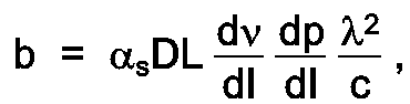
- the CSO attributed to the laser chirp- fiber dispersion combination for a particular channel "j" can be represented as follows: where and Cj is the number of CSO components, m j is the angular frequency at which distortion occurs, m is the modulation index, p is the average optical power, dp dI is the optical slope efficiency, as is the system attenuation, D is the fiber dispersion, L is the fiber length, d ⁇ dI is the laser chirp, ⁇ is the average signal wavelength, and c is the speed of light.
- First post-distortion compensation component 20 1 may be utilized to compensate for the chromatic dispersion described above.
- component 20 1 includes a signal splitter 70 which receives as an input the electronic output signal I(t) from optical receiver 16 (FIG. 1). The output from splitter 70 is subsequent inserted along a first signal path 72 and second signal path 74. Similar to the pre-distortion components discussed above in association with FIG. 2, first signal path 72 includes a delay means 76 for providing an equalizing time delay ⁇ 1 with second signal path 74. As shown, second signal path 74 includes a number of elements which are utilized to compensate for chromatic dispersion.
- second signal path 74 includes a squaring means 78, which is utilized to form the second harmonic of the signal, and a differentiator 80, used to form the j-th derivative of the signal, where in the case of fiber dispersion correction, the first derivative is utilized.
- An attenuator 82 is disposed in second signal path 74 and may be adjusted by the user to provide the correct level of distortion compensation.
- the output from second signal path 74 is defined by the term assuming the first derivative signal is used.
- This distortion compensation signal is subsequently summed with the signal I(t) propagating along first signal path 72 within a summing element 84 to form as an output a first post-distortion signal I'(t).
- a second post-distortion compensation component 20 2 disposed at the output of first component 20 1 , may be used to provide higher-order correction factors to the received signal.
- this component may be used to compensate for composite triple beat (CTB) distortion.
- component 20 2 may comprise a signal splitter 90, responsive to first post-distorted signal I'(t), for providing this signal along a pairofsignal paths 92 and 94, where first path 92 includes delay means 96.
- Second signal path 94 contains a compensation element 98 which functions to form a cubed representation of the applied signal.
- a summing element 100 is used to combine the signals propagating along paths 92 and 94, thus forming as an output a second post-distorted signal I"(t).
- an advantage of the cascaded series arrangement of the present invention is the ability to modify, add and/or delete the various pre- and post-distortion components as the system needs change.
Abstract
Description
- The present invention relates to cascaded distortion compensation for analog optical systems and, more particularly, to an arrangement using a series connection of a plurality of separate pre- and/or post-distortion compensation components, each component capable of providing specific functionality.
- A growing area for analog optical communication systems is the common antenna television (CATV) network. In particular, recent advances in long wavelength distributed feedback (DFB) laser technology have made possible the transport of multiple CATV channels over one single mode fiber at Â=1.3f,.lm. See, for example, "Lightwave subcarrier CATV transmissions systems", by T. E. Darcie et al. appearing in IEEE Trans. Microwave Theory Tech., Vol. MTT-38, p. 524, 1990. The low levels of analog distortions and noise from the DFB lasers have been found to satisfy the system requirements such that the presence of many channels over a common communication path does not noticeably affect the reception of any particular channel.
- It has been well documented, however, that nonlinearities of the DFB laser affect the composite second order (CSO) distortion of the system. Pre-distortion circuits have been developed to compensate for the laser nonlinearity, one exemplary arrangement being disclosed in U.S. Patent 4,992,754 issued to H. A. Blauvelt et al. In this particular arrangement, the distortion is compensated by applying a pre-distorted signal equal in magnitude and opposite in sign to the distortion introduced by the DFB laser. The input signal is split into two paths with the primary part of the signal applied directly to the device, including a time delay to compensate for delays in the secondary path. Apre-distorter in the secondary path generates harmonic signals, the amplitude of which are adjusted to match the amplitude of the distortion. A tilt adjustment is made to compensate the amplitude of the pre-distortion for the frequency dependence of distortion. A fine adjust of the delay is also included so that the phase of the predistortion signal is properly related to the phase of the primary signal.
- Additional sources of nonlinearities not discussed in the Blauvelt et al. reference, for example, the interaction of FM chirp intrinsic to a DFB laser with fiber dispersion, can also affect the system performance, as discussed in the article "Dispersion-Induced Composite Second-Order Distortion at 1.5wm", by E. E. Bergmann et al. appearing in IEEE Photonics Tech. Lett., Vol. 3, No. 1, January 1991, at p. 59. As discussed in the Bergmann et al. reference, dispersion nonlinearity can be counteracted by utilizing dispersion-shifted fiber, reducing laser chirp, or limiting applications to relatively short spans (e.g., <3km). Exemplary predistortion compensation for this combination is discussed in an article entitled "Electrical pre- distortion to Compensate for Combined Effect of Laser Chirp and Fibre Dispersion", by H. Gysel et al. appearing in Electronic Letters, Vol. 27, No. 5 at pp. 421-3. Gysel et al. discusses the utilization of a varactor diode/inductor combination to "build in" the inverse of the expected distortion in the signal as applied to the optical transmitting device.
- Recently, doped fiber amplifiers have become available which can be used in a CATV network to significantly increase the link loss budget. In particular, the erbium doped fiber amplifier (EDFA) is an attractive component since it exhibits high saturated output power, polarization independent amplification, and low intrinsic optical noise. The high saturated output power of an EDFA is of particular importance to CATV transport and distribution applications. Furthermore, its saturated gain characteristic does not respond to input signal variations at speeds fasterthan a few kilohertz because of the small absorption and stimulated emission cross sections, as well as the long metastable lifetime of the erbium ions. However, when an EDFA is used to amplify an analog optical AM CATV multiple carrier signal from a directly modulated DFB laser, an increase in the system distortion is observed.
- In general, the combination of the above-noted dispersion sources, along with other nonlinear components contained within the communication system, such as external modulators and/or erbium-doped fiber amplifiers, results in an overall system-based nonlinear effect which may distort the system performance. Prior art compensation techniques, which address distortion at the component level (i.e., prior to installation in a communication system), cannot provide adequate compensation for the overall analog communication system.
- Thus, a need exists for reducing the signal distortion attributed to the system-level nonlinearity pres- entwithin an operating analog optical communication system.
- The need remaining in the prior art is addressed by the present invention which relates to cascaded distortion compensation for analog optical systems and, more particularly, to an arrangement using a series connection of a plurality of separate pre- and/or post-distortion compensation components, as further defined in the appended claims.
-
- FIG. 1 illustrates an exemplary analog optical communication system utilizing the cascaded series distortion compensation arrangement of the present invention;
- FIG. 2 illustrates an exemplary plurality of cascaded pre-distortion compensation components which may be used with the system illustrated in FIG. 1; and
- FIG. 3 illustrates an exemplary plurality of cascaded post-distortion compensation components which may be used with the system illustrated in FIG. 1.
- FIG. 1 illustrates a generalized block diagram of an exemplary analog
optical communication system 10 utilizing cascaded series distortion compensation in accordance with the teachings of the present invention. In general,system 10 comprises alaser transmitter 12 which is utilized to form an optical communication signal which propagates overoptical fiber 14 to an optical receiver 16 (e.g., PIN-FET receiver). In accordance with the teachings of the present invention a plurality of n pre-distortioncompensation components 18 are disposed in a cascaded series arrangement before the input tolaser transmitter 12. A plurality of Npost-distortion compensation components 20 are illustrated in FIG. 1 as disposed in a cascaded series arrangement after the output of receiver 16 (where n may or may not be equal to N). In operation, an electrical (RF) message signal i(t) is applied as an input to the series arrangement ofpre-distortion components 18 and is modified as it passes therethrough to provide at the output thereof a pre-distorted input signal i"..'(t). Pre-distorted signal i"..'(t) is then applied as an input totransmitter 12 which then generates an optical signal which is sufficiently pre-distorted so as to be essentially linear over the bandwidth of interest. The optical signal subsequently propagates alongoptical fiber 14 and is applied as an input tooptical receiver 16.Optical receiver 16, which may comprise a PIN-FET receiver, then converts the optical signal into an electrical representation I(t). Electrical signal I(t), as converted, contains distortions introduced both by optical fiber 14 (chromatic dispersion) andoptical receiver 16.Post-distortion compensation components 20 are thus coupled to the output ofreceiver 16 and utilizes to substantially compensate for these distortion elements. -
Pre-distortion compensation arrangement 18 comprises a plurality of n separatedistortion compensation components exemplary component 18,. Various other elements, for example, optical amplifiers and/or external modulators, may be located with the laser transmitter and the distortion associated with these elements compensated as required. Similarly,post-distortion compensation arrangement 20 comprises a plurality of N separatedistortion compensation components optical fiber 14 may be compensated by anexemplary component 20,. - As mentioned above, an advantage of the series cascaded arrangement of the present invention is the modularity of the arrangement, that is, the ability to modify separate components without disturbing the compensation characteristics of the remaining compensation components. For example, if a different laser source is substituted for
transmitter 12, a differentdistortion compensation component 18 may be substituted. Likewise, if the receiver is moved to a fiber of different length, for example, thepost-distortion component 20 associated with compensating fiber dispersion may be altered without adjusting the remaining post-distortion components. Therefore, the arrangement of the present invention may be altered as need be by the user to accommodate changes in the environment of the deployed system. - FIG. 2 illustrates an exemplary plurality of =2 predistortion compensation components which may be utilized in
system 10 as illustrated in FIG. 1. In particular, afirst component 181 is utilized to compensate for the inherent nonlinearities of laser transmitter 12 (FIG. 1). As shown,component 181 includes asplitter 30 which functions to direct the incoming (electrical) signal i(t) along afirst signal path 32 and asecond signal path 34.First signal path 32 includes delay means 36 which functions to provide a time delay τ1 to signal i(t) which is substantially identical to the delay associated withsecond signal path 34.Second signal path 34 includes acompensation element 38, for example, a signal squarer, which essentially duplicates (in amplitude, phase and frequency) the particular nonlinearity associated withtransmitter 12. The details of such a compensation scheme are well-known in the art and need not be discussed here. The output fromelement 38 is subsequently inverted in magnitude within aninverter 40. A summingelement 42 is then used to add the original (delayed) signal to the distortion compensation signal to form a first distortion compensated signal i'(t). - As mentioned above, another influence on system nonlinearity may be attributed to the presence of a doped fiber amplifier which is co-located with transmitter 12 (not shown). The contribution to the composite second order (CSO) distortion from such an amplifier has been found to result from inadvertent FM to AM conversion within the doped region of the fiber amplifier. Alternatively, the utilization of a external modulator with the
laser transmitter 12 may form a similar type of distortion. In either case, when a laser source is directly modulated through injection current, its optical frequency varies likewise. When this frequency modulated signal passes through a fiber amplifier (or external modulator), which has wavelength dependent gain G(v), the signal experiences unwanted amplitude modulation, which is then superimposed upon the desired amplitude modulation of the input signal. Therefore, the effective L-I curve from the combination of the laser and amplifier (or modulator) is either super-linear or sub-linear, thus resulting in the unwanted second order distortion. The second order distortion, denoted 2HD, related to the presence of a doped fiber amplifier can be represented as:
where

- The CSO distortion attributed to such amplifiers as described above may be corrected using a
pre-distortion component 182, as shown in FIG. 2. In particular.component 182 is responsive to the first pre-distorted signal i'(t) output fromfirst pre-distortion component 181. As shown,second pre-distortion component 182 includes asplitter 50 for providing pre-distorted signal i'(t) along a pair ofsignal paths 52 and 54. Signal path 52 contains adelay element 56 for provide a predetermined time delay τ2 which essentially equals the time delay alongsecond signal path 54.Second signal path 54 contains a squaringelement 58, anattenuator 60 and time delay means 62 to form a distortion signal of the form aik (t-i2). Asum-ming element 64 is used to add this distortion signal to the first (delayed) distortion signal i'(t) along path 52 to form a second pre-distorted signal i"(t). Signal i"(t) may then be subsequently applied as the input tolaser transmitter 12 of FIG. 1. As mentioned above, various other pre-distortion components may be added to those described above. - FIG. 3 illustrates an exemplary plurality of N =2
post-distortion elements optical communication system 10 is the chromatic dispersion introduced byoptical fiber 14. Studies have indicated that the CSO becomes increasingly large as the length of the fiber increases, and also as the channel frequency increases. Additionally, it has been found that the CSO is worse for lasers with larger chirp. Theoretically, the CSO attributed to the laser chirp- fiber dispersion combination for a particular channel "j" can be represented as follows:

- First
post-distortion compensation component 201, as illustrated in FIG. 3, may be utilized to compensate for the chromatic dispersion described above. In particular,component 201 includes asignal splitter 70 which receives as an input the electronic output signal I(t) from optical receiver 16 (FIG. 1). The output fromsplitter 70 is subsequent inserted along afirst signal path 72 andsecond signal path 74. Similar to the pre-distortion components discussed above in association with FIG. 2,first signal path 72 includes a delay means 76 for providing an equalizing time delay τ1 withsecond signal path 74. As shown,second signal path 74 includes a number of elements which are utilized to compensate for chromatic dispersion. In particular,second signal path 74 includes a squaring means 78, which is utilized to form the second harmonic of the signal, and adifferentiator 80, used to form the j-th derivative of the signal, where in the case of fiber dispersion correction, the first derivative is utilized. Anattenuator 82 is disposed insecond signal path 74 and may be adjusted by the user to provide the correct level of distortion compensation. The output fromsecond signal path 74 is defined by the term
first signal path 72 within a summingelement 84 to form as an output a first post-distortion signal I'(t). - A second
post-distortion compensation component 202, disposed at the output offirst component 201, may be used to provide higher-order correction factors to the received signal. For example, this component may be used to compensate for composite triple beat (CTB) distortion. In particular,component 202 may comprise a signal splitter 90, responsive to first post-distorted signal I'(t), for providing this signal along apairofsignal paths first path 92 includes delay means 96.Second signal path 94 contains acompensation element 98 which functions to form a cubed representation of the applied signal. A summingelement 100 is used to combine the signals propagating alongpaths - It is to be understood that the embodiments described above are exemplary only, and any desired pre- and/or post-distortion compensation component may be used in the cascaded series arrangement of the present invention. As mentioned above, an advantage of the cascaded series arrangement of the present invention is the ability to modify, add and/or delete the various pre- and post-distortion components as the system needs change.
Claims (8)
Applications Claiming Priority (2)
| Application Number | Priority Date | Filing Date | Title |
|---|---|---|---|
| US96431792A | 1992-10-21 | 1992-10-21 | |
| US964317 | 1992-10-21 |
Publications (2)
| Publication Number | Publication Date |
|---|---|
| EP0594344A1 true EP0594344A1 (en) | 1994-04-27 |
| EP0594344B1 EP0594344B1 (en) | 1998-12-23 |
Family
ID=25508396
Family Applications (1)
| Application Number | Title | Priority Date | Filing Date |
|---|---|---|---|
| EP93308139A Expired - Lifetime EP0594344B1 (en) | 1992-10-21 | 1993-10-13 | Cascaded distortion compensation for analog optical systems |
Country Status (5)
| Country | Link |
|---|---|
| US (1) | US5418637A (en) |
| EP (1) | EP0594344B1 (en) |
| JP (1) | JP3014258B2 (en) |
| DE (1) | DE69322733T2 (en) |
| SG (1) | SG52501A1 (en) |
Cited By (6)
| Publication number | Priority date | Publication date | Assignee | Title |
|---|---|---|---|---|
| WO1999049340A2 (en) * | 1998-03-26 | 1999-09-30 | Lasercomm, Inc. | Apparatus and method for compensation of chromatic dispersion in optical fibers |
| DE19846272A1 (en) * | 1998-10-08 | 2000-04-27 | Sel Alcatel Ag | Transmission system for optical communication in which non-coherent signals are transmitted from transmitter to receiver after electric-optic conversion |
| DE19852332A1 (en) * | 1998-11-13 | 2000-05-31 | Alcatel Sa | Transmission module for the transmission of optical signals |
| EP1039631A1 (en) * | 1999-03-23 | 2000-09-27 | Alcatel | Pre/post-distortion circuit and method, particularly for microwave radio-frequency systems |
| WO2000059141A1 (en) * | 1999-03-30 | 2000-10-05 | Jds Uniphase Corporation | Predistortion arrangement using mixers in nonlinear electro-optical applications |
| EP2051416A1 (en) * | 2007-10-15 | 2009-04-22 | Nokia Siemens Networks Oy | Electronic dispersion precompensation for a directly modulated laser |
Families Citing this family (48)
| Publication number | Priority date | Publication date | Assignee | Title |
|---|---|---|---|---|
| US5526159A (en) * | 1992-08-06 | 1996-06-11 | Siemens Aktiengesellschaft | Method and circuit arrangement for electric compensation of signal distortion caused by laser chirp and fiber dispersion |
| US6288814B1 (en) | 1994-05-19 | 2001-09-11 | Ortel Corporation | In-line predistorter for linearization of electronic and optical signals |
| US5798854A (en) * | 1994-05-19 | 1998-08-25 | Ortel Corporation | In-line predistorter for linearization of electronic and optical signals |
| US5963352A (en) * | 1997-02-21 | 1999-10-05 | Scientific-Atlanta, Inc. | Linearization enhanced operation of single-stage and dual-stage electro-optic modulators |
| US6292598B1 (en) * | 1998-11-04 | 2001-09-18 | Corvis Corporation | Optical transmission apparatuses, methods, and systems |
| US6529305B1 (en) | 1998-11-04 | 2003-03-04 | Corvis Corporation | Optical transmission apparatuses, methods, and systems |
| US6118566A (en) | 1998-11-04 | 2000-09-12 | Corvis Corporation | Optical upconverter apparatuses, methods, and systems |
| US6577177B2 (en) | 1999-04-01 | 2003-06-10 | General Instrument Corporation | Non-linear distortion generator |
| ES2184710T3 (en) | 1999-04-01 | 2003-04-16 | Gen Instrument Corp | NON-LINEAR DISTORSION GENERATOR. |
| US6204718B1 (en) | 1999-06-25 | 2001-03-20 | Scientific-Atlanta, Inc. | Method and apparatus for generating second-order predistortion without third-order distortion |
| US6577423B1 (en) | 1999-09-17 | 2003-06-10 | Corvis Corporation | Optical transmission systems, optical receivers, and receiving methods |
| US6587243B1 (en) | 1999-12-10 | 2003-07-01 | General Instrument Corporation | Second order predistortor for a return laser transmitter |
| US6466084B1 (en) | 2000-01-24 | 2002-10-15 | General Instrument Corporation | Circuit for reducing third order intermodulation distortion for a broadband RF amplifier |
| US6509789B1 (en) | 2000-01-24 | 2003-01-21 | General Instrument Corporation | Circuit for reducing second and third order intermodulation distortion for a broadband RF amplifier |
| US7173551B2 (en) * | 2000-12-21 | 2007-02-06 | Quellan, Inc. | Increasing data throughput in optical fiber transmission systems |
| US7307569B2 (en) * | 2001-03-29 | 2007-12-11 | Quellan, Inc. | Increasing data throughput in optical fiber transmission systems |
| US7149256B2 (en) | 2001-03-29 | 2006-12-12 | Quellan, Inc. | Multilevel pulse position modulation for efficient fiber optic communication |
| US7215721B2 (en) * | 2001-04-04 | 2007-05-08 | Quellan, Inc. | Method and system for decoding multilevel signals |
| US20030030873A1 (en) * | 2001-05-09 | 2003-02-13 | Quellan, Inc. | High-speed adjustable multilevel light modulation |
| AU2003211094A1 (en) * | 2002-02-15 | 2003-09-09 | Quellan, Inc. | Multi-level signal clock recovery technique |
| US6816101B2 (en) * | 2002-03-08 | 2004-11-09 | Quelian, Inc. | High-speed analog-to-digital converter using a unique gray code |
| CN1298292C (en) | 2002-03-11 | 2007-02-07 | 贝克顿迪肯森公司 | System and method for the manufacture of surgical blades |
| US7142788B2 (en) * | 2002-04-16 | 2006-11-28 | Corvis Corporation | Optical communications systems, devices, and methods |
| US20030198478A1 (en) * | 2002-04-23 | 2003-10-23 | Quellan, Inc. | Method and system for generating and decoding a bandwidth efficient multi-level signal |
| JP2004013681A (en) * | 2002-06-10 | 2004-01-15 | Bosu & K Consulting Kk | Name card information managing system |
| US6985020B2 (en) * | 2002-07-09 | 2006-01-10 | General Instrument Corporation | Inline predistortion for both CSO and CTB correction |
| AU2003256569A1 (en) * | 2002-07-15 | 2004-02-02 | Quellan, Inc. | Adaptive noise filtering and equalization |
| US20040052536A1 (en) * | 2002-09-17 | 2004-03-18 | General Instrument Corporation | Second order predistortion circuit |
| US7934144B2 (en) | 2002-11-12 | 2011-04-26 | Quellan, Inc. | High-speed analog-to-digital conversion with improved robustness to timing uncertainty |
| US7804760B2 (en) * | 2003-08-07 | 2010-09-28 | Quellan, Inc. | Method and system for signal emulation |
| DE112004001455B4 (en) * | 2003-08-07 | 2020-04-23 | Intersil Americas LLC | Cross-talk cancellation method and system |
| JP4510832B2 (en) | 2003-11-17 | 2010-07-28 | ケラン インコーポレイテッド | Method and system for antenna interference cancellation |
| US7616700B2 (en) | 2003-12-22 | 2009-11-10 | Quellan, Inc. | Method and system for slicing a communication signal |
| US7212746B2 (en) * | 2004-01-23 | 2007-05-01 | Lucent Technologies Inc. | Short haul optical communications |
| US7522883B2 (en) * | 2004-12-14 | 2009-04-21 | Quellan, Inc. | Method and system for reducing signal interference |
| US7725079B2 (en) * | 2004-12-14 | 2010-05-25 | Quellan, Inc. | Method and system for automatic control in an interference cancellation device |
| US7596326B2 (en) * | 2005-10-27 | 2009-09-29 | Emcore Corporation | Distortion cancellation circuitry for optical receivers |
| KR101372361B1 (en) | 2006-04-26 | 2014-03-12 | 인터실 아메리카스 엘엘씨 | Method and system for reducing radiated emissions from a communications channel |
| US7634198B2 (en) * | 2006-06-21 | 2009-12-15 | Emcore Corporation | In-line distortion cancellation circuits for linearization of electronic and optical signals with phase and frequency adjustment |
| US7925170B2 (en) * | 2007-08-07 | 2011-04-12 | Applied Optoelectronics, Inc. | Predistortion circuit including distortion generator diodes with adjustable diode bias |
| US8073340B2 (en) | 2008-02-05 | 2011-12-06 | Applied Optoelectronics, Inc. | Distortion compensation circuit including one or more phase invertible distortion paths |
| US8121493B2 (en) * | 2008-02-05 | 2012-02-21 | Applied Optoelectronics, Inc. | Distortion compensation circuit and method based on orders of time dependent series of distortion signal |
| US9584074B2 (en) * | 2008-02-13 | 2017-02-28 | Arris Enterprises, Inc. | Optical receiver with automatic distortion cancellation |
| US7945172B2 (en) * | 2008-05-20 | 2011-05-17 | Harmonic, Inc. | Dispersion compensation circuitry and system for analog video transmission with direct modulated laser |
| US8643430B2 (en) * | 2010-12-06 | 2014-02-04 | Sensor Electronic Technology, Inc. | Device and circuit with improved linearity |
| US8606116B2 (en) | 2011-01-13 | 2013-12-10 | Applied Optoelectronics, Inc. | System and method for distortion compensation in response to frequency detection |
| US8891974B2 (en) | 2012-03-30 | 2014-11-18 | Applied Optoelectronics, Inc. | Distortion compensation circuit including tunable phase path |
| WO2015160660A1 (en) * | 2014-04-15 | 2015-10-22 | Arris Enterprises, Inc. | Smart receivers and transmitters for catv networks |
Citations (4)
| Publication number | Priority date | Publication date | Assignee | Title |
|---|---|---|---|---|
| JPS5913435A (en) * | 1982-07-15 | 1984-01-24 | Fujitsu Ltd | Circuit for compensating distortion of optical picture link |
| US4943783A (en) * | 1989-07-31 | 1990-07-24 | Nippon Telegraph And Telephone Corporation | Feed forward distortion correction circuit |
| EP0498456A1 (en) * | 1991-02-08 | 1992-08-12 | Ortel Corporation | Predistorter and method for linearization of electronic and optical signals |
| EP0524758A2 (en) * | 1991-07-23 | 1993-01-27 | AT&T Corp. | Distortion compensation for analog optical systems |
Family Cites Families (6)
| Publication number | Priority date | Publication date | Assignee | Title |
|---|---|---|---|---|
| JPH0669167B2 (en) * | 1985-10-04 | 1994-08-31 | 古河電気工業株式会社 | Switching the optical line without interruption |
| GB8909362D0 (en) * | 1989-04-25 | 1989-06-14 | British Telecomm | High gain semiconductor laser amplifier package |
| US4992754B1 (en) * | 1989-09-07 | 1997-10-28 | Ortel Corp | Predistorter for linearization of electronic and optical signals |
| US5210633A (en) * | 1990-09-12 | 1993-05-11 | General Instrument Corporation | Apparatus and method for linearizing the operation of an external optical modulator |
| DE4120029A1 (en) * | 1991-06-18 | 1992-12-24 | Kolbe & Co Hans | CIRCUIT TO REDUCE INTERMODULATION IN THE USE OF SEMICONDUCTOR LASERS FOR THE OPTICAL MESSAGE TRANSMISSION TECHNOLOGY |
| DE4121569A1 (en) * | 1991-06-29 | 1993-01-14 | Standard Elektrik Lorenz Ag | EQUALIZER FOR OPTICALLY TRANSMITTED MESSAGE SIGNALS |
-
1993
- 1993-10-13 SG SG1996005232A patent/SG52501A1/en unknown
- 1993-10-13 EP EP93308139A patent/EP0594344B1/en not_active Expired - Lifetime
- 1993-10-13 DE DE69322733T patent/DE69322733T2/en not_active Expired - Fee Related
- 1993-10-18 JP JP5282160A patent/JP3014258B2/en not_active Expired - Fee Related
-
1994
- 1994-05-16 US US08/243,610 patent/US5418637A/en not_active Expired - Lifetime
Patent Citations (4)
| Publication number | Priority date | Publication date | Assignee | Title |
|---|---|---|---|---|
| JPS5913435A (en) * | 1982-07-15 | 1984-01-24 | Fujitsu Ltd | Circuit for compensating distortion of optical picture link |
| US4943783A (en) * | 1989-07-31 | 1990-07-24 | Nippon Telegraph And Telephone Corporation | Feed forward distortion correction circuit |
| EP0498456A1 (en) * | 1991-02-08 | 1992-08-12 | Ortel Corporation | Predistorter and method for linearization of electronic and optical signals |
| EP0524758A2 (en) * | 1991-07-23 | 1993-01-27 | AT&T Corp. | Distortion compensation for analog optical systems |
Non-Patent Citations (1)
| Title |
|---|
| PATENT ABSTRACTS OF JAPAN vol. 8, no. 95 (E - 242)<1532> 2 May 1984 (1984-05-02) * |
Cited By (9)
| Publication number | Priority date | Publication date | Assignee | Title |
|---|---|---|---|---|
| WO1999049340A2 (en) * | 1998-03-26 | 1999-09-30 | Lasercomm, Inc. | Apparatus and method for compensation of chromatic dispersion in optical fibers |
| WO1999049340A3 (en) * | 1998-03-26 | 1999-11-25 | Lasercomm Inc | Apparatus and method for compensation of chromatic dispersion in optical fibers |
| US6339665B1 (en) | 1998-03-26 | 2002-01-15 | Lasercomm Inc. | Apparatus and method for compensation of chromatic dispersion in optical fibers |
| DE19846272A1 (en) * | 1998-10-08 | 2000-04-27 | Sel Alcatel Ag | Transmission system for optical communication in which non-coherent signals are transmitted from transmitter to receiver after electric-optic conversion |
| DE19852332A1 (en) * | 1998-11-13 | 2000-05-31 | Alcatel Sa | Transmission module for the transmission of optical signals |
| EP1039631A1 (en) * | 1999-03-23 | 2000-09-27 | Alcatel | Pre/post-distortion circuit and method, particularly for microwave radio-frequency systems |
| WO2000059141A1 (en) * | 1999-03-30 | 2000-10-05 | Jds Uniphase Corporation | Predistortion arrangement using mixers in nonlinear electro-optical applications |
| US6519374B1 (en) | 1999-03-30 | 2003-02-11 | Uniphase Corporation | Predistortion arrangement using mixers in nonlinear electro-optical applications |
| EP2051416A1 (en) * | 2007-10-15 | 2009-04-22 | Nokia Siemens Networks Oy | Electronic dispersion precompensation for a directly modulated laser |
Also Published As
| Publication number | Publication date |
|---|---|
| US5418637A (en) | 1995-05-23 |
| SG52501A1 (en) | 1998-09-28 |
| EP0594344B1 (en) | 1998-12-23 |
| DE69322733T2 (en) | 1999-07-01 |
| JPH06232821A (en) | 1994-08-19 |
| DE69322733D1 (en) | 1999-02-04 |
| JP3014258B2 (en) | 2000-02-28 |
Similar Documents
| Publication | Publication Date | Title |
|---|---|---|
| US5418637A (en) | Cascaded distortion compensation for analog optical systems | |
| EP0524758B1 (en) | Distortion compensation for analog optical systems | |
| US7848661B2 (en) | Directly modulated laser optical transmission system with phase modulation | |
| US7881621B2 (en) | Optical transmission system with directly modulated laser and feed forward noise cancellation | |
| US5963352A (en) | Linearization enhanced operation of single-stage and dual-stage electro-optic modulators | |
| US6122085A (en) | Lightwave transmission techniques | |
| US7466925B2 (en) | Directly modulated laser optical transmission system | |
| US5373382A (en) | System of long-distance digital transmission by optical fiber with compensation for distortions at source of transmission | |
| US5812294A (en) | Linearized optical transmitter | |
| KR100437750B1 (en) | Dispersion compensation in optical fiber communications | |
| EP0595140B1 (en) | Method for linearizing an unbalanced Mach Zehnder optical frequency discriminator | |
| US7792432B2 (en) | Externally modulated laser optical transmission system with feed forward noise cancellation | |
| CA2147402A1 (en) | System and method for simultaneously compensating chromatic dispersion and self phase modulation in optical fibers | |
| EP1344336B1 (en) | Method and apparatus for suppressing relative intensity noise (rin) and improving transmission signals in an optical transmission system | |
| US6188823B1 (en) | Method and apparatus for providing dispersion and dispersion slope compensation in an optical communication system | |
| USRE44647E1 (en) | Directly modulated laser optical transmission system with phase modulation | |
| US6819478B1 (en) | Fiber optic transmission system with low cost transmitter compensation | |
| US6917764B1 (en) | Predistortion circuit with combined odd-order and even-order correction | |
| US8064777B2 (en) | Four quadrant linearizer | |
| US6311002B1 (en) | Method and apparatus for reducing nonlinear penalties by proper arrangement of the dispersion map in an optical communication system | |
| Piehler et al. | 55 dB CNR over 50 km of fibre in an 80-channel externally-modulated AM-CATV system without optical amplification | |
| CN101237283B (en) | There is directly modulation or the externally modulated laser optical transmission system of feed-forward noise elimination | |
| JPH08171102A (en) | Optical fiber communication system using optical phase conjugation | |
| JP2013255264A (en) | Directly modulated or externally modulated laser optical transmission system with feed forward noise cancellation | |
| Reid | High bitrate 1310 nm optical transmission in the field using cascaded semiconductor optical amplifiers |
Legal Events
| Date | Code | Title | Description |
|---|---|---|---|
| PUAI | Public reference made under article 153(3) epc to a published international application that has entered the european phase |
Free format text: ORIGINAL CODE: 0009012 |
|
| AK | Designated contracting states |
Kind code of ref document: A1 Designated state(s): DE FR GB IT |
|
| RAP3 | Party data changed (applicant data changed or rights of an application transferred) |
Owner name: AT&T CORP. |
|
| 17P | Request for examination filed |
Effective date: 19941014 |
|
| 17Q | First examination report despatched |
Effective date: 19970624 |
|
| GRAG | Despatch of communication of intention to grant |
Free format text: ORIGINAL CODE: EPIDOS AGRA |
|
| GRAG | Despatch of communication of intention to grant |
Free format text: ORIGINAL CODE: EPIDOS AGRA |
|
| GRAH | Despatch of communication of intention to grant a patent |
Free format text: ORIGINAL CODE: EPIDOS IGRA |
|
| GRAH | Despatch of communication of intention to grant a patent |
Free format text: ORIGINAL CODE: EPIDOS IGRA |
|
| GRAA | (expected) grant |
Free format text: ORIGINAL CODE: 0009210 |
|
| AK | Designated contracting states |
Kind code of ref document: B1 Designated state(s): DE FR GB IT |
|
| ITF | It: translation for a ep patent filed |
Owner name: JACOBACCI & PERANI S.P.A. |
|
| REF | Corresponds to: |
Ref document number: 69322733 Country of ref document: DE Date of ref document: 19990204 |
|
| ET | Fr: translation filed | ||
| PLBE | No opposition filed within time limit |
Free format text: ORIGINAL CODE: 0009261 |
|
| STAA | Information on the status of an ep patent application or granted ep patent |
Free format text: STATUS: NO OPPOSITION FILED WITHIN TIME LIMIT |
|
| 26N | No opposition filed | ||
| REG | Reference to a national code |
Ref country code: GB Ref legal event code: IF02 |
|
| PGFP | Annual fee paid to national office [announced via postgrant information from national office to epo] |
Ref country code: DE Payment date: 20071025 Year of fee payment: 15 |
|
| PGFP | Annual fee paid to national office [announced via postgrant information from national office to epo] |
Ref country code: IT Payment date: 20071025 Year of fee payment: 15 |
|
| PGFP | Annual fee paid to national office [announced via postgrant information from national office to epo] |
Ref country code: GB Payment date: 20071023 Year of fee payment: 15 Ref country code: FR Payment date: 20071016 Year of fee payment: 15 |
|
| GBPC | Gb: european patent ceased through non-payment of renewal fee |
Effective date: 20081013 |
|
| REG | Reference to a national code |
Ref country code: FR Ref legal event code: ST Effective date: 20090630 |
|
| PG25 | Lapsed in a contracting state [announced via postgrant information from national office to epo] |
Ref country code: IT Free format text: LAPSE BECAUSE OF NON-PAYMENT OF DUE FEES Effective date: 20081013 Ref country code: DE Free format text: LAPSE BECAUSE OF NON-PAYMENT OF DUE FEES Effective date: 20090501 |
|
| PG25 | Lapsed in a contracting state [announced via postgrant information from national office to epo] |
Ref country code: FR Free format text: LAPSE BECAUSE OF NON-PAYMENT OF DUE FEES Effective date: 20081031 |
|
| PG25 | Lapsed in a contracting state [announced via postgrant information from national office to epo] |
Ref country code: GB Free format text: LAPSE BECAUSE OF NON-PAYMENT OF DUE FEES Effective date: 20081013 |