EP0595417A1 - Spring device - Google Patents
Spring device Download PDFInfo
- Publication number
- EP0595417A1 EP0595417A1 EP93202969A EP93202969A EP0595417A1 EP 0595417 A1 EP0595417 A1 EP 0595417A1 EP 93202969 A EP93202969 A EP 93202969A EP 93202969 A EP93202969 A EP 93202969A EP 0595417 A1 EP0595417 A1 EP 0595417A1
- Authority
- EP
- European Patent Office
- Prior art keywords
- piston
- axial
- wall
- space
- spring device
- Prior art date
- Legal status (The legal status is an assumption and is not a legal conclusion. Google has not performed a legal analysis and makes no representation as to the accuracy of the status listed.)
- Granted
Links
- 230000002093 peripheral effect Effects 0.000 claims abstract description 33
- 230000004323 axial length Effects 0.000 claims abstract description 10
- 238000007789 sealing Methods 0.000 claims abstract description 10
- 230000007704 transition Effects 0.000 claims abstract description 7
- 239000007789 gas Substances 0.000 description 30
- 239000000463 material Substances 0.000 description 14
- 239000003921 oil Substances 0.000 description 12
- 238000000034 method Methods 0.000 description 8
- 238000006073 displacement reaction Methods 0.000 description 6
- 230000008569 process Effects 0.000 description 6
- 238000006243 chemical reaction Methods 0.000 description 5
- 239000007788 liquid Substances 0.000 description 5
- 230000007423 decrease Effects 0.000 description 4
- 230000009471 action Effects 0.000 description 3
- 230000006835 compression Effects 0.000 description 3
- 238000007906 compression Methods 0.000 description 3
- 238000004519 manufacturing process Methods 0.000 description 3
- IJGRMHOSHXDMSA-UHFFFAOYSA-N Atomic nitrogen Chemical compound N#N IJGRMHOSHXDMSA-UHFFFAOYSA-N 0.000 description 2
- 230000015572 biosynthetic process Effects 0.000 description 2
- 230000001419 dependent effect Effects 0.000 description 2
- 210000005069 ears Anatomy 0.000 description 2
- 239000010720 hydraulic oil Substances 0.000 description 2
- 239000004922 lacquer Substances 0.000 description 2
- 239000002184 metal Substances 0.000 description 2
- 230000000750 progressive effect Effects 0.000 description 2
- 230000009467 reduction Effects 0.000 description 2
- 206010063493 Premature ageing Diseases 0.000 description 1
- 230000002411 adverse Effects 0.000 description 1
- 238000005452 bending Methods 0.000 description 1
- 238000000576 coating method Methods 0.000 description 1
- 230000000295 complement effect Effects 0.000 description 1
- 238000010276 construction Methods 0.000 description 1
- 238000011109 contamination Methods 0.000 description 1
- 238000001816 cooling Methods 0.000 description 1
- 125000004122 cyclic group Chemical group 0.000 description 1
- 238000010586 diagram Methods 0.000 description 1
- 230000000694 effects Effects 0.000 description 1
- 239000012528 membrane Substances 0.000 description 1
- 238000012544 monitoring process Methods 0.000 description 1
- 229910052757 nitrogen Inorganic materials 0.000 description 1
- 239000002245 particle Substances 0.000 description 1
- 238000005096 rolling process Methods 0.000 description 1
- 238000000926 separation method Methods 0.000 description 1
- 238000003860 storage Methods 0.000 description 1
- 238000009423 ventilation Methods 0.000 description 1
Images


Classifications
-
- B—PERFORMING OPERATIONS; TRANSPORTING
- B21—MECHANICAL METAL-WORKING WITHOUT ESSENTIALLY REMOVING MATERIAL; PUNCHING METAL
- B21D—WORKING OR PROCESSING OF SHEET METAL OR METAL TUBES, RODS OR PROFILES WITHOUT ESSENTIALLY REMOVING MATERIAL; PUNCHING METAL
- B21D24/00—Special deep-drawing arrangements in, or in connection with, presses
- B21D24/02—Die-cushions
-
- B—PERFORMING OPERATIONS; TRANSPORTING
- B21—MECHANICAL METAL-WORKING WITHOUT ESSENTIALLY REMOVING MATERIAL; PUNCHING METAL
- B21D—WORKING OR PROCESSING OF SHEET METAL OR METAL TUBES, RODS OR PROFILES WITHOUT ESSENTIALLY REMOVING MATERIAL; PUNCHING METAL
- B21D24/00—Special deep-drawing arrangements in, or in connection with, presses
- B21D24/10—Devices controlling or operating blank holders independently, or in conjunction with dies
- B21D24/14—Devices controlling or operating blank holders independently, or in conjunction with dies pneumatically or hydraulically
Landscapes
- Engineering & Computer Science (AREA)
- Mechanical Engineering (AREA)
- Fluid-Damping Devices (AREA)
- Springs (AREA)
- Finger-Pressure Massage (AREA)
- Glass Compositions (AREA)
- Actuator (AREA)
- Transmission Of Braking Force In Braking Systems (AREA)
Abstract
at least one of the chambers is embodied as a number of chamber parts forming a closed contour, mutually connecting in step-like manner and each having an axial peripheral wall, which chamber parts are bounded axially by successive transverse walls and successive axial peripheral walls of increasing axial lengths, wherein the first piston has a corresponding form and wherein the relevant feed conduit debouches into the chamber part with the smallest cross sectional surface area on the transverse wall, close to this transverse wall on the axial peripheral wall or in the transition zone between the transverse wall and the axial peripheral wall,
a medium drain conduit debouches on the relevant transverse wall close to this transverse wall on the axial peripheral wall or in the transition zone between the transverse wall and the axial peripheral wall, and
valve means are present which only unblock the respective medium drain conduits in a position wherein the connection between the relevant chamber part and the adjoining chamber part is wholly or practically wholly blocked by the first piston.
Description
- The invention relates to a spring device comprising a first housing partly bounding a first space and a first piston which is movable in substantially sealing manner in axial direction in this first space and which is fixedly connected to a piston rod extending in axial direction which co-acts substantially sealingly with a first continuous hole in an end wall of the housing, which first piston divides the said first space into two chambers.
- Such a device embodied as a spring device is generally known. In the known spring device both chambers are filled with medium under pressure, for instance 10-100 bar. Because the piston is provided with a continuous hole the same pressure prevails in both chambers. As a result of the difference in projected effective surface area of both sides of the piston, the piston is pressed under all conditions by the medium pressure to the side of the piston rod. Since the medium pressure and the relevant areas are constant, the spring force produced by the spring device is also constant over the whole active stroke.
- In a drawing or deep-drawing operation, as is generally known, the blank-holder pressure per unit of surface area on the material still to be drawn increases during the deep-draw process. The increasing load per unit of surface area has two causes:
- a) the material surface situated between the blank-holder and the deep-drawing tool becomes smaller,
- b) during the use of a spring or other progressively acting medium the reaction force increases during the deep-draw process.
- The said causes a) and b) provide a greatly increasing blank-holder pressure on the still present material for treating, which results in an undesired material deformation, damage to the material surface, breakage and an irregularly formed rim with four protrusions, so-called ears, which occur at four locations, this at 45° to the rolling direction of the material.
- In order to prevent as far as possible the drawback under point b) use is sometimes made of a non-progressive spring device and in very exceptional cases use is made of a very slow-acting and complicated servo-control system to regulate the bending machine pressure. This latter solution cannot be applied in practice in combination with fast-action production units.
- The invention has for its object to provide a spring device which, during use in co-action with a deep-drawing device, is capable of causing the blank-holder pressure to decrease in proportion to the still remaining material. It is particularly the object to hold substantially constant the blank-holder force per unit of surface area on the as yet non-deformed material.
- The invention generally has for its object to embody a spring device of the said type such that it can be considered a "degressive" spring. Such a spring, be it either a draw spring or compression spring, is defined by the fact that the reaction force exerted by the spring decreases as the displacement between the ends of the spring increases.
- In order to realize the above stated objective the spring device according to the invention has the feature that a feed conduit for feeding medium under pressure connects to each of both chambers,
at least one of the chambers is embodied as a number of chamber parts forming a closed contour, mutually connecting in step-like manner and each having an axial peripheral wall, which chamber parts are bounded axially by successive transverse walls and successive axial peripheral walls of increasing axial lengths, wherein the first piston has a corresponding form and wherein the relevant feed conduit debouches into the chamber part with the smallest cross sectional surface area on the transverse wall, close to this transverse wall on the axial peripheral wall or in the transition zone between the transverse wall and the axial peripheral wall,
a medium drain conduit debouches on the relevant transverse wall close to this transverse wall on the axial peripheral wall or in the transition zone between the transverse wall and the axial peripheral wall, and
valve means are present which only unblock the respective medium drain conduits in a position wherein the connection between the relevant chamber part and the adjoining chamber part is wholly or practically wholly blocked by the first piston. - The said valve means can be linked to the action of the spring device by means of synchronization provisions. An embodiment is however recommended in which the valve means comprise:
a cup-like second housing partly bounding a second space and fixedly coupled to the first housing, and a second piston which is slidable in substantially sealing manner in this second space and which is fixedly connected to the piston rod which co-acts sealingly with a second continuous hole in a wall of the second housing, which second space is connected to a conduit for free draining of medium,
the respective drain conduits in the second space at relative positions corresponding with the mutual differences between the axial lengths of the said axial peripheral walls, and
the second piston has an axial length such that in the one extreme position in which the said of both chambers has its smallest volume it unblocks all drain conduits and in the other extreme position in which the said of both chambers has its largest volume it blocks all drain conduits. - This embodiment can be of very compact and simple structure and have for this purpose the feature that the first housing and the second housing are integrated and are separated by a dividing wall, that the first piston, the second piston and the piston rod are integrated and that both continuous holes are formed by one continuous hole in the dividing wall.
- Separate pressure medium feed conduits can connect to the first and the second chamber. This ensures very great flexibility in the choice of the spring characteristics. A simple embodiment which lacks this flexibility but which is of somewhat simpler construction is characterized by a bypass conduit which connects the smallest of the said chamber parts to the other chamber.
- In such a spring device the same medium pressure always prevails on both sides of the piston, as in any known gas spring. Such a spring is nevertheless of degressive type since the active surface area is dependent on the position which the first piston occupies in the first housing.
- It may be desired to cause the return of the piston to take place at controlled speed. For this purpose the spring device according to the invention can have the feature that the said conduit for free draining of medium comprises an element with adjustable passage.
- The said chamber and associated portion of the piston have in cross section a stepped, complementary structure. In the situation where the relevant step-like chamber has its minimum volume, in particular a zero volume, the axial surfaces of the chamber parts forming a closed contour substantially seal against the oppositely located axial surfaces of the piston which form a closed contour. In this manner a separation between the respective active chamber parts is ensured. When medium under pressure is being admitted into the smallest chamber part via the relevant medium feed conduit, some medium under pressure could already be admitted into the following chamber part or the following chamber parts. This does not have to have an adverse effect on the operation of the spring device but does mean that only limited demands need be made on the seal between the different chamber parts. From a production technique viewpoint this can be very advantageous, while moreover the risk of wear, premature ageing and disturbances is greatly reduced. A spring device which realizes these objectives has the feature that the axial peripheral wall of each chamber part has a small clearance relative to the corresponding axial peripheral walls of the piston.
- From the point of view of production technique the simplest spring device is one having the feature that the chamber parts are bounded by surfaces extending transversely of the axial direction.
- It may be desirable in some conditions for the spring device according to the invention to lend itself to through-feed of machine components. An embodiment suitable for this purpose has the feature that the spring device has a continuous hole extending in axial direction and that the first piston co-acts in sealingly slidable manner with that hole.
- In the case the spring device is used in a deep-draw process, to which the invention is not limited, the following advantages have been observed:
- (a) The formation of "ears" is greatly reduced.
- (b) The decrease in material thickness at the position of rough edges is wholly avoided.
- (c) Pre-applied coatings such as lacquer and the like are no longer damaged during the deep-draw process.
- Secondary advantages are:
- a. The possibility of increasing the deep-drawing ratio.
- b. A better material through-flow during use in combination with complicated tool product forms, rectangular, polygonal, non-round and relief.
- c. Material saving: due to the negligible formation of rough edges, little extra material is needed which has to be trimmed in a later process stage.
- e. A greater efficiency is obtained due to a considerable reduction in the contamination of the deep-draw tool by material splinters and lacquer particles.
- f. Special requirements to be made of the deep-draw material can be partially eliminated.
- The invention will now be elucidated with reference to the annexed drawing, wherein:
- fig. 1 shows a cut away perspective view of a gas spring in a first embodiment;
- fig. 2 shows a view corresponding with fig. 1 of a second embodiment;
- fig. 3 and 4 are cut away side views of a third embodiment in different positions;
- fig. 5 is a cut away side view of a fourth embodiment;
- fig. 6 shows partly in cross section and partly in broken away side view a gas spring with a continuous hole in two respective operating positions;
- fig. 7 shows a detail of a variant of the gas spring according to fig. 6;
- fig. 8a shows schematically a known rubber spring with associated characteristic;
- fig. 8b shows schematically a known spiral spring with associated characteristic;
- fig. 8c shows schematically a known gas spring with associated characteristic;
- fig. 8d shows schematically the degressive spring according to the invention with a graphic illustration of the range within which the spring characteristic can be freely adjusted at the wish of the user; and
- fig. 9 shows a cross section through a spring device according to the invention which operates with liquid medium under pressure.
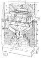
- Fig. 1 shows a
degressive gas spring 1 in a first embodiment according to the invention.Gas spring 1 comprises afirst housing 3 partly bounding afirst space 2 and afirst piston 5 which is movable in substantially sealing manner in axial direction 4 in thisfirst space 2 and which is fixedly connected to apiston rod 6 which extends in axial direction and which co-acts substantially sealingly with acontinuous hole 7 in anend wall 8 ofhousing 3, whichfirst piston 5 divides the saidfirst space 2 into two chambers, namely alower chamber 9 and anupper chamber 10. - A first feed conduit for medium under pressure connects onto the
lower chamber 9. Asecond feed conduit 12 for medium under pressure connects onto the upper chamber. - The
upper chamber 10 is embodied as threechamber parts peripheral wall chamber parts transverse wall portions 19, 20, 21 respectively (which in this embodiment are oriented perpendicularly of the axial direction 4) with increasing surface areas, wherein the successive axialperipheral walls first piston 5 has a corresponding form. Thefeed conduit 12 debouches onwall portion 19, that is, the wall portion which adjoins thepiston rod 6 and has the smallest surface area. -
Medium drain conduits second space 24 which is bounded by a second housing 25 formed integrally with thefirst housing 3 and having a general cup shape. Asecond piston 26 is slidable substantially, in any case more or less, sealingly in thesecond space 24. Thesecond piston 26 is carried by thepiston rod 6. Connecting onto thesecond space 24 is a conduit for free draining of medium out of thesecond space 24. - The
medium drain conduits second space 24 at relative positions in accordance with the mutual differences between the axial lengths of the said axialperipheral walls second piston 26 has an axial length, that is, a length along which it co-acts sealingly with the edge of thesecond space 24, such that in the one extreme position in which theupper chamber 10 has its smallest volume it unblocks bothmedium drain conduits upper chamber 10 has its largest volume it blocks bothmedium drain conduits - An
element 28 with adjustable passage is arranged in the conduit 27. - The
peripheral walls - The second housing 25 supports a deep-drawing
device 29. Ametal plate 30 is inserted between the edges of twomould parts Mould part 31 has acontinuous hole 34 for passage of athird mould part 33 which has a form corresponding with the desired form of a deep-drawn plate. Thesecond mould part 32 has a correspondingly formedcavity 35. Through relative displacement ofmould parts metal plate 30 clamped betweenmould parts mould cavity 35 by themould part 33. During this deep-draw process a relatively downward directed force is exerted onmould part 32 which is transferred via force transmitting pins 36 (which extend through a dividing wall 37) onto thesecond piston 26, whereby thefirst piston 5 ofgas spring 1 is pressed downward. - By means of unillustrated means medium under pressure is fed via the
first feed conduit 11 and thesecond feed conduit 12 to respectively thelower chamber 9 and theupper chamber 10. In the uppermost position drawn in this figure thepiston 5 still closes off thesecond feed conduit 12 entirely. When thefirst piston 5 is displaced in downward direction a pressure is exerted by the relevant medium on the upper flat surface 38 ofpiston 5. The reaction force applied bygas spring 1 hereby decreases. As displacement continues medium pressure is also exerted on the secondflat surface 39 of the piston, which causes further reduction of the reaction force applied bygas spring 1. With still further displacement the third flat surface of thepistons 5 is also loaded by medium pressure whereby the smallest possible reaction force remains. - After the gas spring has thus been moved from the position shown in fig. 1 to the other extreme position in which the
upper chamber 10 has its maximum volume, it must be returned to the starting position. The pressure in thelower chamber 9 carries back thefirst piston 5, wherein medium can first escape from thechamber part 5 viamedium drain conduit 23 to thespace 24 to then be drained via conduit 27. For this purpose thesecond piston 26 has meanwhile been displaced into a position in which it unblocks the debouchment of saidconduit 23 intospace 24. Draining of medium fromchamber part 14 subsequently takes place viamedium drain conduit 22 which has meanwhile been unblocked by thepiston 26. - The draining of medium from
chamber part 13 does not require an extra conduit, since this chamber part is connected via theconduit 12 to a source of medium under pressure. - Due to the presence of the
element 28 with adjustable passage, the speed at whichgas spring 1 is reset can be adjusted in accordance with the wishes of the user. At the beginning of a following work stroke the pressure in thesecond space 24 must again be atmospheric. - It is important to note that owing to the cyclic ventilation of the
chamber parts - It will further be apparent that the spring characteristic realized is dependent on the dimensioning of the gas spring and the pressure of the medium fed via the
conduits - As a result of the fact that the axial
peripheral walls peripheral walls first piston 5, pressure medium admitted into thechamber part 13 can to a limited extent already flow through tochamber part 14. Medium can then flow smoothly out ofchamber part 14 tochamber part 15. This can further a smooth, i.e. non-jerky, operation of the gas spring. The speed of the piston also contributes to this smooth action. - Fig. 2 shows a
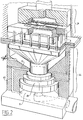
gas spring 44 with the deep-drawingdevice 29. The structure ofgas spring 44 differs from the embodiment of fig. 1 only in the presence ofbypass conduit 45 which connects thelower chamber 9 to theupper chamber 10. The same medium pressure hereby always prevails in these twochambers - Fig. 3 and 4 show a
gas spring 46 in two positions. For the sake of simplicity elements corresponding functionally with the elements of fig. 1 and 2 are designated with the same reference numerals as in the discussion of fig. 1 and 2. - Fig. 3 shows clearly that in the situation where the
chamber part 13 is active and thechamber part 14 is on the point of becoming active, the debouchment of themedium drain conduit 22 into thesecond space 24 is on the point of being closed by thepiston 26. - Fig. 4 shows that in the position wherein, after
chamber part 14,chamber part 15 also becomes active, the debouchment of themedium drain conduit 23 into thesecond space 24 is also blocked by thepiston 26. - Fig. 5 shows a
gas spring 47 in which theupper chamber 10 consists of four chamber parts, namely thechamber parts additional chamber part 48. This debouches via amedium drain conduit 49 into thesecond space 24 below the debouchment of themedium drain conduit 23. - It can be seen in this embodiment that the
first piston 5 co-acts sealingly with thefirst housing 3 via a sealingring 50. Thepiston rod 6 is also guided sealingly in thecontinuous hole 7 by a sealingring 51. - Fig. 6 shows a
gas spring 55 with a centralcontinuous hole 56. In this respect thefirst piston 57 is sealingly slidable relative to this hole. Use is made for this purpose of abottom part 58 with acentral cylinder 59, whichcylinder 59 co-acts with thefirst piston 57 by means of a sealingring 60. - Functionally the
gas spring 55 corresponds substantially with thegas spring 44 according to fig. 2. It is however important to note that there are a number of differences which make it desirable to discuss this important embodiment. Thebypass conduit 45 shown in fig. 2 is implemented in this embodiment as a free space serving as a conduit. Other than in theembodiments second feed conduit 12 debouches on theperipheral wall 16 of thefirst chamber part 13. Thegas spring 55 hereby acts in the first part of the stroke, in which thepiston 57 still fully closes off the debouchment ofconduit 12, as a normal gas spring. Only after theconduit 12 has been partially unblocked does the degressive action according to the invention take place. - Fig. 7 shows a detail of a variant in which the
second feed conduit 12 debouches into thechamber part 13 in the transition zone between the flattransverse wall portion 19 and theperipheral wall 16. - Attention is drawn to the fact that particularly in an embodiment as according to fig. 6 the possibility exists of selecting the form of debouchment of the
conduit 12 intochamber part 13 with a view to a specific desired characteristic. Use can for instance be made of a more or less wedge-shaped outflow opening whereby medium can be admitted progressively tochamber part 13 viaconduit 12. - Fig. 8 shows a comparison between three known springs and the degressive spring device according to the invention.
- Fig. 8a shows a spring provided with a
rubber block 52 with the associated spring characteristic. Shown vertically is the force, horizontally the compression of the spring. It is assumed in the characteristic that the spring has a certain bias. - Fig. 8b shows a
normal spiral spring 53 with associated characteristic. The rubber block spring and the spiral spring have in common that the spring characteristics display a progressive nature. - Fig. 8c shows a
typical gas spring 54. It can be seen from the spring characteristic that the compression force is substantially constant. - Fig. 8d shows schematically the
gas spring 1 according to the invention. It can be seen from the accompanying characteristic that practically any spring characteristic can be realized inside the hatched section by suitable choice of the gas pressures in combination with the design of the dimensioning of the gas spring. - Fig. 9 shows a
hydraulic spring device 61 of the degressive type. The above discussed figures 1-7 all related to degressive spring devices based on the use of gas under pressure as medium. Thespring device 61 is based on a liquid as medium. Since a liquid is non-compressible, means are necessary, otherwise than in the use of gas, to ensure that, as the pressure builds up, the liquid can escape where necessary in order to enable relative movement of the piston and the cylinder, while on the other hand means must also be present to build up and maintain this pressure, and particularly to hold it substantially constant during a work cycle. - The structure of the
device 61 corresponds by and large with that as according to fig. 1. It will therefore suffice to discuss a number of components which do not appear in fig. 1. - A hydraulic system depicted in the form of a block diagram is connected to the cylinder-
piston unit 62. Situated in areservoir 63 is a liquid medium such as hydraulic oil. Apump 64 driven by amotor 65 brings the hydraulic oil to the pressure required for operation of theunit 62. The oil under pressure is supplied via a pressure regulator-regulatingvalve 66 to an inlet 67 of theunit 62. Monitoring of the pressure is carried out by ameter 68. The oil thus brought under pressure can act to exert pressure on the upper part ofpiston 69, analogously to the foregoing discussion of the gas springs. For return of the oil to thereservoir 63 during upward directed movement ofpiston 69 use is made of four conduits which are grouped as manifold and therefore designated jointly with thereference numeral 70. Viaopenings 71, which during displacement of thepiston 69 are opened or closed selectively by a cylinder jacket-like valve member 72, the oil can flow back into a cylinder jacket-like space 73 which can carry the oil back to theoil reservoir 63 via adrain 74. It is noted that owing to theconnections 67 and 74 the oil can flow in both directions subject to the movement condition ofpiston 69. - An
insert piece 76 partly bounding the cylinder jacket-like space 73 limits the volume of thespace 63, whereby the quantity of oil for displacement can remain comparatively limited, so that at higher speeds the danger of cavitations is prevented and the mass of oil to be displaced remains limited. - It is remarked that where necessary sealing rings are arranged. These are all designated with the
reference numeral 77. Placed on the outlet ofpump 64 is an overpressuresafety control valve 78 which can return oil to thereservoir 63. - The outlet of
pump 64 is also connected to a knownpressure storage reservoir 79, apressure gauge 80 and anadjustable tap 81 which in turn is connected to apressure gauge 82, a second pressure reservoir 83 and aconnection 84 on the underside of the cylinder/piston unit 62. Situated in reservoir 83 is an up and downward movable piston or amembrane 85 which is adjustably biased by nitrogen under pressure designated with thereference numeral 86. During normal use thevalve 81 is closed. Should leakage occur somewhere in the system, whereby pressure loss or a shortage of oil occurs, thevalve 81 is opened and oil under pressure is admitted into the system as required.
Claims (8)
- Spring device comprising a first housing partly bounding a first space and a first piston which is movable in substantially sealing manner in axial direction in this first space and which is fixedly connected to a piston rod extending in axial direction which co-acts substantially sealingly with a first continuous hole in an end wall of the housing, which first piston divides the said first space into two chambers,
characterized in that
a feed conduit for feeding medium under pressure connects to each of both chambers,
at least one of the chambers is embodied as a number of chamber parts forming a closed contour, mutually connecting in step-like manner and each having an axial peripheral wall, which chamber parts are bounded axially by successive transverse walls and successive axial peripheral walls of increasing axial lengths, wherein the first piston has a corresponding form and wherein the relevant feed conduit debouches into the chamber part with the smallest cross sectional surface area on the transverse wall, close to this transverse wall on the axial peripheral wall or in the transition zone between the transverse wall and the axial peripheral wall, a medium drain conduit debouches on the relevant transverse wall, close to this transverse wall on the axial peripheral wall or in the transition zone between the transverse wall and the axial peripheral wall, and
valve means are present which only unblock the respective medium drain conduits in a position wherein the connection between the relevant chamber part and the adjoining chamber part is wholly or practically wholly blocked by the first piston. - Spring device as claimed in claim 1, characterized in that the valve means comprise:
a cup-like second housing partly bounding a second space and fixedly coupled to the first housing, and a second piston which is slidable in substantially sealing manner in this second space and which is fixedly connected to the piston rod which co-acts sealingly with a second continuous hole in a wall of the second housing, which second space is connected to a conduit for free draining of medium,
the respective drain conduits in the second space at relative positions corresponding with the mutual differences between the axial lengths of the said axial peripheral walls, and
the second piston has an axial length such that in the one extreme position in which the said of both chambers has its smallest volume it unblocks all drain conduits and in the other extreme position in which the said of both chambers has its largest volume it blocks all drain conduits. - Spring device as claimed in claim 2, characterized in that the first housing and the second housing are integrated and are separated by a dividing wall, that the first piston, the second piston and the piston rod are integrated and that both continuous holes are formed by one continuous hole in the dividing wall.
- Spring device as claimed in claim 1, characterized by a bypass conduit which connects the smallest of the said chamber parts to the other chamber.
- Spring device as claimed in claim 2, characterized in that the said conduit for free draining of medium comprises an element with adjustable passage.
- Spring device as claimed in claim 1, characterized in that the axial peripheral wall of each chamber part has a small clearance relative to the corresponding axial peripheral walls of the piston.
- Spring device as claimed in claim 1, characterized in that the chamber parts are bounded by surfaces extending transversely of the axial direction.
- Spring device as claimed in claim 1, characterized in that the spring device has a continuous hole extending in axial direction and that the first piston co-acts in sealingly slidable manner with that hole.
Applications Claiming Priority (2)
| Application Number | Priority Date | Filing Date | Title |
|---|---|---|---|
| NL9201857A NL9201857A (en) | 1992-10-26 | 1992-10-26 | DEGRESSIVE GAS SPRING. |
| NL9201857 | 1992-10-26 |
Publications (2)
| Publication Number | Publication Date |
|---|---|
| EP0595417A1 true EP0595417A1 (en) | 1994-05-04 |
| EP0595417B1 EP0595417B1 (en) | 1997-06-18 |
Family
ID=19861427
Family Applications (1)
| Application Number | Title | Priority Date | Filing Date |
|---|---|---|---|
| EP93202969A Expired - Lifetime EP0595417B1 (en) | 1992-10-26 | 1993-10-22 | Spring device |
Country Status (10)
| Country | Link |
|---|---|
| US (1) | US5454549A (en) |
| EP (1) | EP0595417B1 (en) |
| JP (1) | JP3816963B2 (en) |
| KR (1) | KR0164439B1 (en) |
| AT (1) | ATE154530T1 (en) |
| CA (1) | CA2109137C (en) |
| DE (1) | DE69311672T2 (en) |
| ES (1) | ES2107613T3 (en) |
| NL (1) | NL9201857A (en) |
| TW (1) | TW227595B (en) |
Cited By (2)
| Publication number | Priority date | Publication date | Assignee | Title |
|---|---|---|---|---|
| EP1859875A2 (en) * | 2006-05-26 | 2007-11-28 | Diebolt International, Inc. | Reaction device for forming equipment |
| WO2008092486A1 (en) * | 2007-02-01 | 2008-08-07 | Saeta Gmbh & Co. Kg | Method and device for deep drawing blanks made of sheet metal into flangeless molded blanks |
Families Citing this family (1)
| Publication number | Priority date | Publication date | Assignee | Title |
|---|---|---|---|---|
| DE19800661B4 (en) * | 1998-01-10 | 2005-05-19 | Burkhard Oest | Gas spring with adjustable gas volume |
Citations (5)
| Publication number | Priority date | Publication date | Assignee | Title |
|---|---|---|---|---|
| US3420089A (en) * | 1966-02-16 | 1969-01-07 | Mc Donnell Douglas Corp | Variable pressure drawpress and method |
| GB1481202A (en) * | 1976-03-29 | 1977-07-27 | Metal Box Co Ltd | Deep drawing |
| FR2343526A1 (en) * | 1976-03-10 | 1977-10-07 | Etscheid Gmbh Hermann | PRESSING DEVICE FOR DEEP STAMPING PRESS |
| US4745792A (en) * | 1986-10-14 | 1988-05-24 | Aluminum Company Of America | Blankholder for a draw press |
| GB2200862A (en) * | 1987-02-09 | 1988-08-17 | Redicon Corp | Controlling material holding pressure in a single acting forming press |
Family Cites Families (4)
| Publication number | Priority date | Publication date | Assignee | Title |
|---|---|---|---|---|
| US1967245A (en) * | 1931-02-20 | 1934-07-24 | American Can Co | Art of drawing |
| US2143429A (en) * | 1936-10-14 | 1939-01-10 | Frank Tea & Spice Company | Apparatus for forming sheet metal forms |
| US3267715A (en) * | 1961-10-16 | 1966-08-23 | Dro Engineering Company Di | Hydraulic control for dies in ram type presses |
| US4873859A (en) * | 1987-02-09 | 1989-10-17 | Redicon Corporation | Apparatus for controlling movement in a single action forming press |
-
1992
- 1992-10-26 NL NL9201857A patent/NL9201857A/en not_active Application Discontinuation
-
1993
- 1993-10-20 TW TW082108728A patent/TW227595B/zh active
- 1993-10-22 ES ES93202969T patent/ES2107613T3/en not_active Expired - Lifetime
- 1993-10-22 EP EP93202969A patent/EP0595417B1/en not_active Expired - Lifetime
- 1993-10-22 DE DE69311672T patent/DE69311672T2/en not_active Expired - Fee Related
- 1993-10-22 AT AT93202969T patent/ATE154530T1/en not_active IP Right Cessation
- 1993-10-25 CA CA002109137A patent/CA2109137C/en not_active Expired - Fee Related
- 1993-10-25 JP JP26624493A patent/JP3816963B2/en not_active Expired - Lifetime
- 1993-10-26 US US08/143,566 patent/US5454549A/en not_active Expired - Fee Related
- 1993-10-26 KR KR1019930022268A patent/KR0164439B1/en not_active IP Right Cessation
Patent Citations (5)
| Publication number | Priority date | Publication date | Assignee | Title |
|---|---|---|---|---|
| US3420089A (en) * | 1966-02-16 | 1969-01-07 | Mc Donnell Douglas Corp | Variable pressure drawpress and method |
| FR2343526A1 (en) * | 1976-03-10 | 1977-10-07 | Etscheid Gmbh Hermann | PRESSING DEVICE FOR DEEP STAMPING PRESS |
| GB1481202A (en) * | 1976-03-29 | 1977-07-27 | Metal Box Co Ltd | Deep drawing |
| US4745792A (en) * | 1986-10-14 | 1988-05-24 | Aluminum Company Of America | Blankholder for a draw press |
| GB2200862A (en) * | 1987-02-09 | 1988-08-17 | Redicon Corp | Controlling material holding pressure in a single acting forming press |
Cited By (5)
| Publication number | Priority date | Publication date | Assignee | Title |
|---|---|---|---|---|
| EP1859875A2 (en) * | 2006-05-26 | 2007-11-28 | Diebolt International, Inc. | Reaction device for forming equipment |
| EP1859875A3 (en) * | 2006-05-26 | 2008-01-23 | Diebolt International, Inc. | Reaction device for forming equipment |
| WO2008092486A1 (en) * | 2007-02-01 | 2008-08-07 | Saeta Gmbh & Co. Kg | Method and device for deep drawing blanks made of sheet metal into flangeless molded blanks |
| CN101678428B (en) * | 2007-02-01 | 2012-05-30 | 赛塔有限责任两合公司 | Device for deep drawing blanks made of sheet metal into flangeless molded blanks |
| US9283611B2 (en) | 2007-02-01 | 2016-03-15 | Saeta Gmbh & Co Kg | Method and device for deep drawing blanks made of sheet metal into flangeless moulded blanks |
Also Published As
| Publication number | Publication date |
|---|---|
| EP0595417B1 (en) | 1997-06-18 |
| JP3816963B2 (en) | 2006-08-30 |
| ATE154530T1 (en) | 1997-07-15 |
| US5454549A (en) | 1995-10-03 |
| TW227595B (en) | 1994-08-01 |
| CA2109137A1 (en) | 1994-04-27 |
| KR0164439B1 (en) | 1999-01-15 |
| CA2109137C (en) | 1999-07-27 |
| JPH06241258A (en) | 1994-08-30 |
| KR940008806A (en) | 1994-05-16 |
| DE69311672T2 (en) | 1998-01-08 |
| NL9201857A (en) | 1993-10-18 |
| ES2107613T3 (en) | 1997-12-01 |
| DE69311672D1 (en) | 1997-07-24 |
Similar Documents
| Publication | Publication Date | Title |
|---|---|---|
| CA1280039C (en) | Drawing installation for a press | |
| CA2163313C (en) | Apparatus including mutually communicating hydraulic cylinders for even distribution of blank-holding force on pressing machine | |
| US4229965A (en) | Hydraulic circuit of a hydromechanical drawing press | |
| US5341723A (en) | Reciprocating pneumatic motor for hydraulics | |
| CA2012802A1 (en) | Hydraulic compression tool having improved relief/release valve | |
| WO1989002793A1 (en) | Power press with improved cushioning system | |
| CA1052234A (en) | Two step pressure intensifier system | |
| US5810567A (en) | Hydraulic Diaphragm pump | |
| JPH06179100A (en) | Seal device for use in press assembly | |
| EP0595417B1 (en) | Spring device | |
| US8057198B2 (en) | Variable displacement piezo-electric pumps | |
| EP0538724B1 (en) | Index-feed machining system | |
| US4457498A (en) | Force balanced die cylinders | |
| EP0092253B1 (en) | Metal sheet forming process with hydraulic counterpressure | |
| JPH09303463A (en) | Gas-sealed shock absorbing member | |
| EP0273721A2 (en) | A booster type driving device for a press-machine | |
| JPH0777163A (en) | Diaphragm pump | |
| EP0543177B1 (en) | Hydraulic actuator | |
| GB2201735A (en) | A control system for a rotary compressor | |
| US2507194A (en) | Shape-forming device | |
| US4195565A (en) | Fluid-operated press | |
| US3316926A (en) | Pressure responsive supply-exhaust valve | |
| US3046923A (en) | Hydraulic stamping press with a die made of resilient material | |
| JPH0350121B2 (en) | ||
| JP3657503B2 (en) | Pressure equalizing cylinder device and method of assembling the pressure equalizing cylinder device |
Legal Events
| Date | Code | Title | Description |
|---|---|---|---|
| PUAI | Public reference made under article 153(3) epc to a published international application that has entered the european phase |
Free format text: ORIGINAL CODE: 0009012 |
|
| AK | Designated contracting states |
Kind code of ref document: A1 Designated state(s): AT BE CH DE DK ES FR GB GR IE IT LI LU MC NL PT SE |
|
| 17P | Request for examination filed |
Effective date: 19940517 |
|
| GRAG | Despatch of communication of intention to grant |
Free format text: ORIGINAL CODE: EPIDOS AGRA |
|
| 17Q | First examination report despatched |
Effective date: 19960507 |
|
| GRAH | Despatch of communication of intention to grant a patent |
Free format text: ORIGINAL CODE: EPIDOS IGRA |
|
| GRAH | Despatch of communication of intention to grant a patent |
Free format text: ORIGINAL CODE: EPIDOS IGRA |
|
| GRAA | (expected) grant |
Free format text: ORIGINAL CODE: 0009210 |
|
| AK | Designated contracting states |
Kind code of ref document: B1 Designated state(s): AT BE CH DE DK ES FR GB GR IE IT LI LU MC NL PT SE |
|
| PG25 | Lapsed in a contracting state [announced via postgrant information from national office to epo] |
Ref country code: GR Free format text: LAPSE BECAUSE OF FAILURE TO SUBMIT A TRANSLATION OF THE DESCRIPTION OR TO PAY THE FEE WITHIN THE PRESCRIBED TIME-LIMIT Effective date: 19970618 Ref country code: DK Effective date: 19970618 |
|
| REF | Corresponds to: |
Ref document number: 154530 Country of ref document: AT Date of ref document: 19970715 Kind code of ref document: T |
|
| REG | Reference to a national code |
Ref country code: CH Ref legal event code: EP |
|
| REF | Corresponds to: |
Ref document number: 69311672 Country of ref document: DE Date of ref document: 19970724 |
|
| ITF | It: translation for a ep patent filed |
Owner name: STUDIO INGG. FISCHETTI & WEBER |
|
| PG25 | Lapsed in a contracting state [announced via postgrant information from national office to epo] |
Ref country code: PT Effective date: 19970918 |
|
| ET | Fr: translation filed | ||
| PG25 | Lapsed in a contracting state [announced via postgrant information from national office to epo] |
Ref country code: LU Free format text: LAPSE BECAUSE OF NON-PAYMENT OF DUE FEES Effective date: 19971031 |
|
| REG | Reference to a national code |
Ref country code: ES Ref legal event code: FG2A Ref document number: 2107613 Country of ref document: ES Kind code of ref document: T3 |
|
| REG | Reference to a national code |
Ref country code: CH Ref legal event code: NV Representative=s name: ARNOLD & SIEDSMA AG |
|
| PLBE | No opposition filed within time limit |
Free format text: ORIGINAL CODE: 0009261 |
|
| STAA | Information on the status of an ep patent application or granted ep patent |
Free format text: STATUS: NO OPPOSITION FILED WITHIN TIME LIMIT |
|
| PG25 | Lapsed in a contracting state [announced via postgrant information from national office to epo] |
Ref country code: MC Free format text: LAPSE BECAUSE OF NON-PAYMENT OF DUE FEES Effective date: 19980430 |
|
| 26N | No opposition filed | ||
| PGFP | Annual fee paid to national office [announced via postgrant information from national office to epo] |
Ref country code: AT Payment date: 20001109 Year of fee payment: 8 |
|
| PGFP | Annual fee paid to national office [announced via postgrant information from national office to epo] |
Ref country code: FR Payment date: 20001113 Year of fee payment: 8 |
|
| PGFP | Annual fee paid to national office [announced via postgrant information from national office to epo] |
Ref country code: IE Payment date: 20001117 Year of fee payment: 8 Ref country code: CH Payment date: 20001117 Year of fee payment: 8 |
|
| PGFP | Annual fee paid to national office [announced via postgrant information from national office to epo] |
Ref country code: SE Payment date: 20001120 Year of fee payment: 8 Ref country code: GB Payment date: 20001120 Year of fee payment: 8 |
|
| PGFP | Annual fee paid to national office [announced via postgrant information from national office to epo] |
Ref country code: NL Payment date: 20001123 Year of fee payment: 8 |
|
| PGFP | Annual fee paid to national office [announced via postgrant information from national office to epo] |
Ref country code: ES Payment date: 20001130 Year of fee payment: 8 |
|
| PGFP | Annual fee paid to national office [announced via postgrant information from national office to epo] |
Ref country code: BE Payment date: 20001218 Year of fee payment: 8 |
|
| PG25 | Lapsed in a contracting state [announced via postgrant information from national office to epo] |
Ref country code: IE Free format text: LAPSE BECAUSE OF FAILURE TO SUBMIT A TRANSLATION OF THE DESCRIPTION OR TO PAY THE FEE WITHIN THE PRESCRIBED TIME-LIMIT Effective date: 20011022 Ref country code: GB Free format text: LAPSE BECAUSE OF NON-PAYMENT OF DUE FEES Effective date: 20011022 Ref country code: AT Free format text: LAPSE BECAUSE OF NON-PAYMENT OF DUE FEES Effective date: 20011022 |
|
| PG25 | Lapsed in a contracting state [announced via postgrant information from national office to epo] |
Ref country code: SE Free format text: LAPSE BECAUSE OF NON-PAYMENT OF DUE FEES Effective date: 20011023 Ref country code: ES Free format text: LAPSE BECAUSE OF NON-PAYMENT OF DUE FEES Effective date: 20011023 |
|
| PG25 | Lapsed in a contracting state [announced via postgrant information from national office to epo] |
Ref country code: LI Free format text: LAPSE BECAUSE OF NON-PAYMENT OF DUE FEES Effective date: 20011031 Ref country code: CH Free format text: LAPSE BECAUSE OF NON-PAYMENT OF DUE FEES Effective date: 20011031 Ref country code: BE Free format text: LAPSE BECAUSE OF NON-PAYMENT OF DUE FEES Effective date: 20011031 |
|
| REG | Reference to a national code |
Ref country code: GB Ref legal event code: IF02 |
|
| BERE | Be: lapsed |
Owner name: KAMPFER HANS-PETER Effective date: 20011031 |
|
| PG25 | Lapsed in a contracting state [announced via postgrant information from national office to epo] |
Ref country code: NL Free format text: LAPSE BECAUSE OF NON-PAYMENT OF DUE FEES Effective date: 20020501 |
|
| EUG | Se: european patent has lapsed |
Ref document number: 93202969.7 |
|
| GBPC | Gb: european patent ceased through non-payment of renewal fee |
Effective date: 20011022 |
|
| REG | Reference to a national code |
Ref country code: CH Ref legal event code: PL |
|
| PG25 | Lapsed in a contracting state [announced via postgrant information from national office to epo] |
Ref country code: FR Free format text: LAPSE BECAUSE OF NON-PAYMENT OF DUE FEES Effective date: 20020628 |
|
| NLV4 | Nl: lapsed or anulled due to non-payment of the annual fee |
Effective date: 20020501 |
|
| REG | Reference to a national code |
Ref country code: IE Ref legal event code: MM4A |
|
| REG | Reference to a national code |
Ref country code: FR Ref legal event code: ST |
|
| REG | Reference to a national code |
Ref country code: ES Ref legal event code: FD2A Effective date: 20021113 |
|
| PG25 | Lapsed in a contracting state [announced via postgrant information from national office to epo] |
Ref country code: IT Free format text: LAPSE BECAUSE OF NON-PAYMENT OF DUE FEES Effective date: 20051022 |
|
| PGFP | Annual fee paid to national office [announced via postgrant information from national office to epo] |
Ref country code: DE Payment date: 20071213 Year of fee payment: 15 |
|
| PG25 | Lapsed in a contracting state [announced via postgrant information from national office to epo] |
Ref country code: DE Free format text: LAPSE BECAUSE OF NON-PAYMENT OF DUE FEES Effective date: 20090501 |