EP0595782A2 - Anchoring element supporting prostheses or a joint mechanism for a reconstructed joint - Google Patents
Anchoring element supporting prostheses or a joint mechanism for a reconstructed joint Download PDFInfo
- Publication number
- EP0595782A2 EP0595782A2 EP93850201A EP93850201A EP0595782A2 EP 0595782 A2 EP0595782 A2 EP 0595782A2 EP 93850201 A EP93850201 A EP 93850201A EP 93850201 A EP93850201 A EP 93850201A EP 0595782 A2 EP0595782 A2 EP 0595782A2
- Authority
- EP
- European Patent Office
- Prior art keywords
- anchoring element
- anchoring
- threads
- slits
- bore
- Prior art date
- Legal status (The legal status is an assumption and is not a legal conclusion. Google has not performed a legal analysis and makes no representation as to the accuracy of the status listed.)
- Granted
Links
Images

Classifications
-
- A—HUMAN NECESSITIES
- A61—MEDICAL OR VETERINARY SCIENCE; HYGIENE
- A61F—FILTERS IMPLANTABLE INTO BLOOD VESSELS; PROSTHESES; DEVICES PROVIDING PATENCY TO, OR PREVENTING COLLAPSING OF, TUBULAR STRUCTURES OF THE BODY, e.g. STENTS; ORTHOPAEDIC, NURSING OR CONTRACEPTIVE DEVICES; FOMENTATION; TREATMENT OR PROTECTION OF EYES OR EARS; BANDAGES, DRESSINGS OR ABSORBENT PADS; FIRST-AID KITS
- A61F2/00—Filters implantable into blood vessels; Prostheses, i.e. artificial substitutes or replacements for parts of the body; Appliances for connecting them with the body; Devices providing patency to, or preventing collapsing of, tubular structures of the body, e.g. stents
- A61F2/02—Prostheses implantable into the body
- A61F2/30—Joints
- A61F2/30721—Accessories
- A61F2/30749—Fixation appliances for connecting prostheses to the body
-
- A—HUMAN NECESSITIES
- A61—MEDICAL OR VETERINARY SCIENCE; HYGIENE
- A61B—DIAGNOSIS; SURGERY; IDENTIFICATION
- A61B17/00—Surgical instruments, devices or methods, e.g. tourniquets
- A61B17/56—Surgical instruments or methods for treatment of bones or joints; Devices specially adapted therefor
- A61B17/58—Surgical instruments or methods for treatment of bones or joints; Devices specially adapted therefor for osteosynthesis, e.g. bone plates, screws, setting implements or the like
- A61B17/68—Internal fixation devices, including fasteners and spinal fixators, even if a part thereof projects from the skin
- A61B17/84—Fasteners therefor or fasteners being internal fixation devices
- A61B17/86—Pins or screws or threaded wires; nuts therefor
- A61B17/8625—Shanks, i.e. parts contacting bone tissue
-
- A—HUMAN NECESSITIES
- A61—MEDICAL OR VETERINARY SCIENCE; HYGIENE
- A61F—FILTERS IMPLANTABLE INTO BLOOD VESSELS; PROSTHESES; DEVICES PROVIDING PATENCY TO, OR PREVENTING COLLAPSING OF, TUBULAR STRUCTURES OF THE BODY, e.g. STENTS; ORTHOPAEDIC, NURSING OR CONTRACEPTIVE DEVICES; FOMENTATION; TREATMENT OR PROTECTION OF EYES OR EARS; BANDAGES, DRESSINGS OR ABSORBENT PADS; FIRST-AID KITS
- A61F2/00—Filters implantable into blood vessels; Prostheses, i.e. artificial substitutes or replacements for parts of the body; Appliances for connecting them with the body; Devices providing patency to, or preventing collapsing of, tubular structures of the body, e.g. stents
- A61F2/02—Prostheses implantable into the body
- A61F2/30—Joints
- A61F2/30721—Accessories
-
- A—HUMAN NECESSITIES
- A61—MEDICAL OR VETERINARY SCIENCE; HYGIENE
- A61F—FILTERS IMPLANTABLE INTO BLOOD VESSELS; PROSTHESES; DEVICES PROVIDING PATENCY TO, OR PREVENTING COLLAPSING OF, TUBULAR STRUCTURES OF THE BODY, e.g. STENTS; ORTHOPAEDIC, NURSING OR CONTRACEPTIVE DEVICES; FOMENTATION; TREATMENT OR PROTECTION OF EYES OR EARS; BANDAGES, DRESSINGS OR ABSORBENT PADS; FIRST-AID KITS
- A61F2/00—Filters implantable into blood vessels; Prostheses, i.e. artificial substitutes or replacements for parts of the body; Appliances for connecting them with the body; Devices providing patency to, or preventing collapsing of, tubular structures of the body, e.g. stents
- A61F2/02—Prostheses implantable into the body
- A61F2/30—Joints
- A61F2/42—Joints for wrists or ankles; for hands, e.g. fingers; for feet, e.g. toes
- A61F2/4241—Joints for wrists or ankles; for hands, e.g. fingers; for feet, e.g. toes for hands, e.g. fingers
-
- A—HUMAN NECESSITIES
- A61—MEDICAL OR VETERINARY SCIENCE; HYGIENE
- A61B—DIAGNOSIS; SURGERY; IDENTIFICATION
- A61B17/00—Surgical instruments, devices or methods, e.g. tourniquets
- A61B17/56—Surgical instruments or methods for treatment of bones or joints; Devices specially adapted therefor
- A61B17/58—Surgical instruments or methods for treatment of bones or joints; Devices specially adapted therefor for osteosynthesis, e.g. bone plates, screws, setting implements or the like
- A61B17/68—Internal fixation devices, including fasteners and spinal fixators, even if a part thereof projects from the skin
- A61B17/686—Plugs, i.e. elements forming interface between bone hole and implant or fastener, e.g. screw
-
- A—HUMAN NECESSITIES
- A61—MEDICAL OR VETERINARY SCIENCE; HYGIENE
- A61B—DIAGNOSIS; SURGERY; IDENTIFICATION
- A61B17/00—Surgical instruments, devices or methods, e.g. tourniquets
- A61B17/56—Surgical instruments or methods for treatment of bones or joints; Devices specially adapted therefor
- A61B17/58—Surgical instruments or methods for treatment of bones or joints; Devices specially adapted therefor for osteosynthesis, e.g. bone plates, screws, setting implements or the like
- A61B17/68—Internal fixation devices, including fasteners and spinal fixators, even if a part thereof projects from the skin
- A61B17/84—Fasteners therefor or fasteners being internal fixation devices
- A61B17/86—Pins or screws or threaded wires; nuts therefor
- A61B17/864—Pins or screws or threaded wires; nuts therefor hollow, e.g. with socket or cannulated
-
- A—HUMAN NECESSITIES
- A61—MEDICAL OR VETERINARY SCIENCE; HYGIENE
- A61B—DIAGNOSIS; SURGERY; IDENTIFICATION
- A61B17/00—Surgical instruments, devices or methods, e.g. tourniquets
- A61B17/56—Surgical instruments or methods for treatment of bones or joints; Devices specially adapted therefor
- A61B17/58—Surgical instruments or methods for treatment of bones or joints; Devices specially adapted therefor for osteosynthesis, e.g. bone plates, screws, setting implements or the like
- A61B17/68—Internal fixation devices, including fasteners and spinal fixators, even if a part thereof projects from the skin
- A61B17/84—Fasteners therefor or fasteners being internal fixation devices
- A61B17/86—Pins or screws or threaded wires; nuts therefor
- A61B17/8685—Pins or screws or threaded wires; nuts therefor comprising multiple separate parts
-
- A—HUMAN NECESSITIES
- A61—MEDICAL OR VETERINARY SCIENCE; HYGIENE
- A61F—FILTERS IMPLANTABLE INTO BLOOD VESSELS; PROSTHESES; DEVICES PROVIDING PATENCY TO, OR PREVENTING COLLAPSING OF, TUBULAR STRUCTURES OF THE BODY, e.g. STENTS; ORTHOPAEDIC, NURSING OR CONTRACEPTIVE DEVICES; FOMENTATION; TREATMENT OR PROTECTION OF EYES OR EARS; BANDAGES, DRESSINGS OR ABSORBENT PADS; FIRST-AID KITS
- A61F2/00—Filters implantable into blood vessels; Prostheses, i.e. artificial substitutes or replacements for parts of the body; Appliances for connecting them with the body; Devices providing patency to, or preventing collapsing of, tubular structures of the body, e.g. stents
- A61F2/02—Prostheses implantable into the body
- A61F2/30—Joints
- A61F2002/30001—Additional features of subject-matter classified in A61F2/28, A61F2/30 and subgroups thereof
- A61F2002/30316—The prosthesis having different structural features at different locations within the same prosthesis; Connections between prosthetic parts; Special structural features of bone or joint prostheses not otherwise provided for
- A61F2002/30535—Special structural features of bone or joint prostheses not otherwise provided for
- A61F2002/30593—Special structural features of bone or joint prostheses not otherwise provided for hollow
-
- A—HUMAN NECESSITIES
- A61—MEDICAL OR VETERINARY SCIENCE; HYGIENE
- A61F—FILTERS IMPLANTABLE INTO BLOOD VESSELS; PROSTHESES; DEVICES PROVIDING PATENCY TO, OR PREVENTING COLLAPSING OF, TUBULAR STRUCTURES OF THE BODY, e.g. STENTS; ORTHOPAEDIC, NURSING OR CONTRACEPTIVE DEVICES; FOMENTATION; TREATMENT OR PROTECTION OF EYES OR EARS; BANDAGES, DRESSINGS OR ABSORBENT PADS; FIRST-AID KITS
- A61F2/00—Filters implantable into blood vessels; Prostheses, i.e. artificial substitutes or replacements for parts of the body; Appliances for connecting them with the body; Devices providing patency to, or preventing collapsing of, tubular structures of the body, e.g. stents
- A61F2/02—Prostheses implantable into the body
- A61F2/30—Joints
- A61F2002/30001—Additional features of subject-matter classified in A61F2/28, A61F2/30 and subgroups thereof
- A61F2002/30316—The prosthesis having different structural features at different locations within the same prosthesis; Connections between prosthetic parts; Special structural features of bone or joint prostheses not otherwise provided for
- A61F2002/30535—Special structural features of bone or joint prostheses not otherwise provided for
- A61F2002/30594—Special structural features of bone or joint prostheses not otherwise provided for slotted, e.g. radial or meridian slot ending in a polar aperture, non-polar slots, horizontal or arcuate slots
-
- A—HUMAN NECESSITIES
- A61—MEDICAL OR VETERINARY SCIENCE; HYGIENE
- A61F—FILTERS IMPLANTABLE INTO BLOOD VESSELS; PROSTHESES; DEVICES PROVIDING PATENCY TO, OR PREVENTING COLLAPSING OF, TUBULAR STRUCTURES OF THE BODY, e.g. STENTS; ORTHOPAEDIC, NURSING OR CONTRACEPTIVE DEVICES; FOMENTATION; TREATMENT OR PROTECTION OF EYES OR EARS; BANDAGES, DRESSINGS OR ABSORBENT PADS; FIRST-AID KITS
- A61F2/00—Filters implantable into blood vessels; Prostheses, i.e. artificial substitutes or replacements for parts of the body; Appliances for connecting them with the body; Devices providing patency to, or preventing collapsing of, tubular structures of the body, e.g. stents
- A61F2/02—Prostheses implantable into the body
- A61F2/30—Joints
- A61F2002/30001—Additional features of subject-matter classified in A61F2/28, A61F2/30 and subgroups thereof
- A61F2002/30667—Features concerning an interaction with the environment or a particular use of the prosthesis
- A61F2002/30677—Means for introducing or releasing pharmaceutical products, e.g. antibiotics, into the body
-
- A—HUMAN NECESSITIES
- A61—MEDICAL OR VETERINARY SCIENCE; HYGIENE
- A61F—FILTERS IMPLANTABLE INTO BLOOD VESSELS; PROSTHESES; DEVICES PROVIDING PATENCY TO, OR PREVENTING COLLAPSING OF, TUBULAR STRUCTURES OF THE BODY, e.g. STENTS; ORTHOPAEDIC, NURSING OR CONTRACEPTIVE DEVICES; FOMENTATION; TREATMENT OR PROTECTION OF EYES OR EARS; BANDAGES, DRESSINGS OR ABSORBENT PADS; FIRST-AID KITS
- A61F2/00—Filters implantable into blood vessels; Prostheses, i.e. artificial substitutes or replacements for parts of the body; Appliances for connecting them with the body; Devices providing patency to, or preventing collapsing of, tubular structures of the body, e.g. stents
- A61F2/02—Prostheses implantable into the body
- A61F2/30—Joints
- A61F2/30767—Special external or bone-contacting surface, e.g. coating for improving bone ingrowth
- A61F2/30771—Special external or bone-contacting surface, e.g. coating for improving bone ingrowth applied in original prostheses, e.g. holes or grooves
- A61F2002/30772—Apertures or holes, e.g. of circular cross section
- A61F2002/30782—Apertures or holes, e.g. of circular cross section inclined obliquely
-
- A—HUMAN NECESSITIES
- A61—MEDICAL OR VETERINARY SCIENCE; HYGIENE
- A61F—FILTERS IMPLANTABLE INTO BLOOD VESSELS; PROSTHESES; DEVICES PROVIDING PATENCY TO, OR PREVENTING COLLAPSING OF, TUBULAR STRUCTURES OF THE BODY, e.g. STENTS; ORTHOPAEDIC, NURSING OR CONTRACEPTIVE DEVICES; FOMENTATION; TREATMENT OR PROTECTION OF EYES OR EARS; BANDAGES, DRESSINGS OR ABSORBENT PADS; FIRST-AID KITS
- A61F2/00—Filters implantable into blood vessels; Prostheses, i.e. artificial substitutes or replacements for parts of the body; Appliances for connecting them with the body; Devices providing patency to, or preventing collapsing of, tubular structures of the body, e.g. stents
- A61F2/02—Prostheses implantable into the body
- A61F2/30—Joints
- A61F2/30767—Special external or bone-contacting surface, e.g. coating for improving bone ingrowth
- A61F2/30771—Special external or bone-contacting surface, e.g. coating for improving bone ingrowth applied in original prostheses, e.g. holes or grooves
- A61F2002/30772—Apertures or holes, e.g. of circular cross section
- A61F2002/30784—Plurality of holes
- A61F2002/30785—Plurality of holes parallel
-
- A—HUMAN NECESSITIES
- A61—MEDICAL OR VETERINARY SCIENCE; HYGIENE
- A61F—FILTERS IMPLANTABLE INTO BLOOD VESSELS; PROSTHESES; DEVICES PROVIDING PATENCY TO, OR PREVENTING COLLAPSING OF, TUBULAR STRUCTURES OF THE BODY, e.g. STENTS; ORTHOPAEDIC, NURSING OR CONTRACEPTIVE DEVICES; FOMENTATION; TREATMENT OR PROTECTION OF EYES OR EARS; BANDAGES, DRESSINGS OR ABSORBENT PADS; FIRST-AID KITS
- A61F2/00—Filters implantable into blood vessels; Prostheses, i.e. artificial substitutes or replacements for parts of the body; Appliances for connecting them with the body; Devices providing patency to, or preventing collapsing of, tubular structures of the body, e.g. stents
- A61F2/02—Prostheses implantable into the body
- A61F2/30—Joints
- A61F2/30767—Special external or bone-contacting surface, e.g. coating for improving bone ingrowth
- A61F2/30771—Special external or bone-contacting surface, e.g. coating for improving bone ingrowth applied in original prostheses, e.g. holes or grooves
- A61F2002/30772—Apertures or holes, e.g. of circular cross section
- A61F2002/30784—Plurality of holes
- A61F2002/30787—Plurality of holes inclined obliquely with respect to each other
-
- A—HUMAN NECESSITIES
- A61—MEDICAL OR VETERINARY SCIENCE; HYGIENE
- A61F—FILTERS IMPLANTABLE INTO BLOOD VESSELS; PROSTHESES; DEVICES PROVIDING PATENCY TO, OR PREVENTING COLLAPSING OF, TUBULAR STRUCTURES OF THE BODY, e.g. STENTS; ORTHOPAEDIC, NURSING OR CONTRACEPTIVE DEVICES; FOMENTATION; TREATMENT OR PROTECTION OF EYES OR EARS; BANDAGES, DRESSINGS OR ABSORBENT PADS; FIRST-AID KITS
- A61F2/00—Filters implantable into blood vessels; Prostheses, i.e. artificial substitutes or replacements for parts of the body; Appliances for connecting them with the body; Devices providing patency to, or preventing collapsing of, tubular structures of the body, e.g. stents
- A61F2/02—Prostheses implantable into the body
- A61F2/30—Joints
- A61F2/30767—Special external or bone-contacting surface, e.g. coating for improving bone ingrowth
- A61F2/30771—Special external or bone-contacting surface, e.g. coating for improving bone ingrowth applied in original prostheses, e.g. holes or grooves
- A61F2002/30841—Sharp anchoring protrusions for impaction into the bone, e.g. sharp pins, spikes
- A61F2002/30845—Sharp anchoring protrusions for impaction into the bone, e.g. sharp pins, spikes with cutting edges
-
- A—HUMAN NECESSITIES
- A61—MEDICAL OR VETERINARY SCIENCE; HYGIENE
- A61F—FILTERS IMPLANTABLE INTO BLOOD VESSELS; PROSTHESES; DEVICES PROVIDING PATENCY TO, OR PREVENTING COLLAPSING OF, TUBULAR STRUCTURES OF THE BODY, e.g. STENTS; ORTHOPAEDIC, NURSING OR CONTRACEPTIVE DEVICES; FOMENTATION; TREATMENT OR PROTECTION OF EYES OR EARS; BANDAGES, DRESSINGS OR ABSORBENT PADS; FIRST-AID KITS
- A61F2/00—Filters implantable into blood vessels; Prostheses, i.e. artificial substitutes or replacements for parts of the body; Appliances for connecting them with the body; Devices providing patency to, or preventing collapsing of, tubular structures of the body, e.g. stents
- A61F2/02—Prostheses implantable into the body
- A61F2/30—Joints
- A61F2/30767—Special external or bone-contacting surface, e.g. coating for improving bone ingrowth
- A61F2/30771—Special external or bone-contacting surface, e.g. coating for improving bone ingrowth applied in original prostheses, e.g. holes or grooves
- A61F2002/3085—Special external or bone-contacting surface, e.g. coating for improving bone ingrowth applied in original prostheses, e.g. holes or grooves with a threaded, e.g. self-tapping, bone-engaging surface, e.g. external surface
-
- A—HUMAN NECESSITIES
- A61—MEDICAL OR VETERINARY SCIENCE; HYGIENE
- A61F—FILTERS IMPLANTABLE INTO BLOOD VESSELS; PROSTHESES; DEVICES PROVIDING PATENCY TO, OR PREVENTING COLLAPSING OF, TUBULAR STRUCTURES OF THE BODY, e.g. STENTS; ORTHOPAEDIC, NURSING OR CONTRACEPTIVE DEVICES; FOMENTATION; TREATMENT OR PROTECTION OF EYES OR EARS; BANDAGES, DRESSINGS OR ABSORBENT PADS; FIRST-AID KITS
- A61F2/00—Filters implantable into blood vessels; Prostheses, i.e. artificial substitutes or replacements for parts of the body; Appliances for connecting them with the body; Devices providing patency to, or preventing collapsing of, tubular structures of the body, e.g. stents
- A61F2/02—Prostheses implantable into the body
- A61F2/30—Joints
- A61F2/30767—Special external or bone-contacting surface, e.g. coating for improving bone ingrowth
- A61F2/30771—Special external or bone-contacting surface, e.g. coating for improving bone ingrowth applied in original prostheses, e.g. holes or grooves
- A61F2002/30904—Special external or bone-contacting surface, e.g. coating for improving bone ingrowth applied in original prostheses, e.g. holes or grooves serrated profile, i.e. saw-toothed
-
- A—HUMAN NECESSITIES
- A61—MEDICAL OR VETERINARY SCIENCE; HYGIENE
- A61F—FILTERS IMPLANTABLE INTO BLOOD VESSELS; PROSTHESES; DEVICES PROVIDING PATENCY TO, OR PREVENTING COLLAPSING OF, TUBULAR STRUCTURES OF THE BODY, e.g. STENTS; ORTHOPAEDIC, NURSING OR CONTRACEPTIVE DEVICES; FOMENTATION; TREATMENT OR PROTECTION OF EYES OR EARS; BANDAGES, DRESSINGS OR ABSORBENT PADS; FIRST-AID KITS
- A61F2/00—Filters implantable into blood vessels; Prostheses, i.e. artificial substitutes or replacements for parts of the body; Appliances for connecting them with the body; Devices providing patency to, or preventing collapsing of, tubular structures of the body, e.g. stents
- A61F2/02—Prostheses implantable into the body
- A61F2/30—Joints
- A61F2/32—Joints for the hip
- A61F2/36—Femoral heads ; Femoral endoprostheses
- A61F2/3662—Femoral shafts
- A61F2002/3678—Geometrical features
- A61F2002/368—Geometrical features with lateral apertures, bores, holes or openings, e.g. for reducing the mass, for receiving fixation screws or for communicating with the inside of a hollow shaft
-
- A—HUMAN NECESSITIES
- A61—MEDICAL OR VETERINARY SCIENCE; HYGIENE
- A61F—FILTERS IMPLANTABLE INTO BLOOD VESSELS; PROSTHESES; DEVICES PROVIDING PATENCY TO, OR PREVENTING COLLAPSING OF, TUBULAR STRUCTURES OF THE BODY, e.g. STENTS; ORTHOPAEDIC, NURSING OR CONTRACEPTIVE DEVICES; FOMENTATION; TREATMENT OR PROTECTION OF EYES OR EARS; BANDAGES, DRESSINGS OR ABSORBENT PADS; FIRST-AID KITS
- A61F2/00—Filters implantable into blood vessels; Prostheses, i.e. artificial substitutes or replacements for parts of the body; Appliances for connecting them with the body; Devices providing patency to, or preventing collapsing of, tubular structures of the body, e.g. stents
- A61F2/02—Prostheses implantable into the body
- A61F2/30—Joints
- A61F2/32—Joints for the hip
- A61F2/36—Femoral heads ; Femoral endoprostheses
- A61F2/3662—Femoral shafts
- A61F2002/3678—Geometrical features
- A61F2002/3694—Geometrical features with longitudinal bores
-
- A—HUMAN NECESSITIES
- A61—MEDICAL OR VETERINARY SCIENCE; HYGIENE
- A61F—FILTERS IMPLANTABLE INTO BLOOD VESSELS; PROSTHESES; DEVICES PROVIDING PATENCY TO, OR PREVENTING COLLAPSING OF, TUBULAR STRUCTURES OF THE BODY, e.g. STENTS; ORTHOPAEDIC, NURSING OR CONTRACEPTIVE DEVICES; FOMENTATION; TREATMENT OR PROTECTION OF EYES OR EARS; BANDAGES, DRESSINGS OR ABSORBENT PADS; FIRST-AID KITS
- A61F2/00—Filters implantable into blood vessels; Prostheses, i.e. artificial substitutes or replacements for parts of the body; Appliances for connecting them with the body; Devices providing patency to, or preventing collapsing of, tubular structures of the body, e.g. stents
- A61F2/02—Prostheses implantable into the body
- A61F2/30—Joints
- A61F2/32—Joints for the hip
- A61F2/36—Femoral heads ; Femoral endoprostheses
- A61F2/3662—Femoral shafts
- A61F2002/3678—Geometrical features
- A61F2002/3698—Geometrical features twisted about the longitudinal axis of the shaft
-
- A—HUMAN NECESSITIES
- A61—MEDICAL OR VETERINARY SCIENCE; HYGIENE
- A61F—FILTERS IMPLANTABLE INTO BLOOD VESSELS; PROSTHESES; DEVICES PROVIDING PATENCY TO, OR PREVENTING COLLAPSING OF, TUBULAR STRUCTURES OF THE BODY, e.g. STENTS; ORTHOPAEDIC, NURSING OR CONTRACEPTIVE DEVICES; FOMENTATION; TREATMENT OR PROTECTION OF EYES OR EARS; BANDAGES, DRESSINGS OR ABSORBENT PADS; FIRST-AID KITS
- A61F2310/00—Prostheses classified in A61F2/28 or A61F2/30 - A61F2/44 being constructed from or coated with a particular material
- A61F2310/00005—The prosthesis being constructed from a particular material
- A61F2310/00011—Metals or alloys
- A61F2310/00023—Titanium or titanium-based alloys, e.g. Ti-Ni alloys
Definitions
- the present invention relates to an anchoring element for supporting prostheses, said anchoring element having essentially the form of a screw and being arranged for connection by its outer end portion to said protheses and by its opposite inner end portion to be inserted and anchored in bone tissue.
- the invention can also be used for supporting a joint mechanism, but is preferably used in reconstructions after amputations or other defects.
- Anchoring of prostheses in bone tissue by anchoring elements having essentially the form av a screw is known in the art. Excellent results have been obtained in respect of osseointegration of such implant elements and their preserved function with dental prostheses anchored in the jaw bone by fixtures according to a method developed by professor Br ⁇ nemark and co-workers. In addition to fixture design, non-traumatic surgery techniques and properties of fixture material and surface have been of importance in this respect.
- US 5,171,284 proposes a rotationally symmetric, at least partially hollow anchoring element for reconstruction of joints, particularly for reconstruction of finger joints.
- This known anchoring element has essentially rotationally symmetric form and is provided with external threads on the major part of its outside and arranged for connection at its outer end portion to said prosthesis or parts thereof, and for insertion and anchoring in bone tissue by its opposite inner end portion, wherein at least one slit with cutting edges extends from the inner end of the anchoring element in direction of the outer end portion of the element.
- the mantle surface of the known anchoring element may have holes that are advantageously formed like cutting edges.
- the fixture is self-tapping. This further reduces the trauma caused during implantation, resulting in promotion of the integration by the healing process.
- the bone material removed by ablation in the tapping process is received by said slits or cavities and is restructured or resorbed by-and-by.
- the known anchoring element has however been designed for anchoring of small joints, particularly finger joints; in this context, the bore in which the fixture is to be secured by screwing is arranged in a hole made in the longitudinal direction of the bone. In such case the amount of bone material removed by tapping is comparatively small.
- the self-tapping properties of such a fixture may however be further improved, particularly if the fixture is intended to be used for larger joints, for self-tapping in dense bone tissue or at a larger depth of fixation, in which case the bone material removed by tapping will have a larger volume for which sufficient space has to be provided in cavities or slits of the fixture.
- an anchoring element which is provided with a centred through bore and having a slit or slits arranged in spiral form around the longitudinal axis of the anchoring element and extending over the major part of the threaded outside provided with external threads, the chirality of the slit being the same as that of the external threads.
- the wall thickness of the anchoring element to progressively decreasing over a portion near the inner end and in direction towards the inner end.
- a bridge of material is arranged between the slit walls and along a slit portion extending from the closed end of the slit, said bridge of material being penetrated by at least one hole, the inner wall of said bridge being delimited by the centred bore and the thickness of the brigde in a radial direction being substantially smaller than the radial wall thickness of the portion of the element bordering the portion of the slit provided with bridges.
- the lateral walls of the slit prefferably be plane-parallel to each other and for the hole or holes penetrating the bridge of material to be circular, the diameter of said holes being substantially the similar to the slit width.
- the centred bore widens in direction of the inner end of the element.
- the widening of the bore is substantially conical. It is preferred for the anchoring element to lack bridges bridging the spiral slits in its portion widening in direction of the inner end of the element.
- the inner end of the element has the form of an intersected annular edge, the radius of which substantially corresponds to the inner diameter of the exterior threads.
- the number of spiral slits is two or three or a multiple of two; if the number is two or a multiple of two the slits in each pair are arranged opposite to each other in respect of the centre bore axis; in all intersectional planes perpendicular to said axis neighbouring slits are equidistant from each other.
- the area occupied by slits in said portion of the anchoring element provided with slits to be between 15 and 50 %.
- the ratio between the pitch of the exterior threads and the pitch of each spiral slit is between 20 : 1 and 500 : 1, preferably about 100 : 1.
- the outer wall portion bordering the inner end may lack threads but to have been appropriately coarsely worked in a lathe, and for the inner portion of the anchoring element to be somewhat radially resilient.
- the fixation means for a prosthesis or a part of a prosthesis comprise internal threads and/or a hexagonal portion arranged at the outer end portion of the anchoring element.
- the element prefferably has a bore in its outer end portion, said bore being tilted in respect of the centre axis by an angle ⁇ of between 25 and 65° to provide for passage of a nerve or a feeding means or for a sinew or for external communication.
- the anchoring element is preferably of titanium or another tissue-friendly material, and is provided, at least in regard of the portion of its surface having contact with tissue upon implantatiom, with a micropitted surface, the pit diameter being between 10 and 1 000 nm, preferably between 10 - 300 nm.
- the anchoring element according to the invention is intended for use in securing prostheses or parts thereof in bone tissue or for external communication or transmission of biologic and physical parameters.
- the invention also discloses a method for anchoring an anchoring element for prostheses or parts of prostheses in bone tissue, said anchoring element having a hollow centre and being provided with external threads and self-tapping means, said process comprising production of a hole in bone tissue, the diameter of said hole approximately corresponding to the inner diameter of the external threads of the anchoring element, said hole having a length adapted to the insertion depth of the element, insertion of the element into the hole by self-tapping screwing-on while removing bone material by ablation and thereby forming threads in the bone material, said threads corresponding to the external threads of the anchoring element, whereby the removed bone material is received by one or several grooves provided in the outer wall of the anchoring element and is transported in the grooves in the direction of the outer end portion of the anchoring element, and anchoring the element in the bone by cooperation of its external threads with the threads cut into the bone tissue, fixation of a prosthesis or a part of a prosthesis to the outer end of the anchoring
- said method further comprise post-implantation supply of pharmacologically active agents, such as agents promoting integration by the healing process and bactericides, said supply being fed through the symmetrically centred bore of the anchoring element to the bone tissue area provided with the hole for implantation of the element.
- pharmacologically active agents such as agents promoting integration by the healing process and bactericides
- the anchoring element 1 according to the invention shown in Fig. 1 is of pure titanium that had been worked in a lathe and has the approximate shape of a cylindric sleeve with a symmetrically centred through bore 2. On its outside the mantle of the cylindric sleeve is provided with threads 20 commencing adjacent to the one, inner end 7, and extending in direction of the other, outer end 8, said threads covering the major part of the mantle, except for a narrow zone 9 having a width of about one thread pitch and a comparatively wider zone 10 adjacent to outer end 8.
- the portion of the cylinder mantle provided with outer threads comprises two sections, one non-segmented section 12 (shown in fig 4C) bordering the wider outer end zone 10, and a section 11 divided into four segments in the longitudinal direction of the element (shown in Figs. 4D to 4H) extending between the non-segmented section 12 and the narrow inner end zone 9 segmented in the same way as segmented section 11.
- Segmentation of the inner end zone 9 and the section 11 bordering threreon into four segments 33, 44, 55, 66 about circular in transsection is due to four slits 3, 4, 5, 6 dissecting the cylinder wall and communicating with centre bore 2.
- Slits 3, 4, 5, 6 have spiral form and are symmetrically positioned in respect of the centre axis 13 of the cylinder bore and have parallel side walls 41, 42 and open ends coinciding with the inner end 7 of the element.
- Slits 3, 4, 5, 6 ar closed at their other ends defined by the border between segmented portion 11 and non-segmented portion 12.
- the ratio of pitch of slits 3, 4, 5, 6 to pitch of exterior threads 20 is about 100 : 1, each of slits 3, 4, 5, 6 corresponding to a fourth of a full thread (thread segment of 90°; rotational angle ⁇ in Fig. 4). Rotation of slits 3, 4, 5, 6 and thus of segments 33, 44, 55, 66 thus is plainly evident from the sections in Fig. 4D - 4H.
- Segmentation of anchoring element 1 is complete only in one portion extending from the inner end 7 in direction of the outer end 8 and bordering a partially segmented portion 16 (shown in Fig. 4D, 4E, 4F) comprising the remaining part of the segmented section.
- the partial segmentation is due to material bridges 23 (section through such a bridge is shown in Fig. 4E) connecting segments 33, 44, 55, 66 and which, in respect of centre axis 13, extends from bore 2 outwards in radial direction, having a thickness in this direction of about a fourth of the radial thickness of the threaded cylinder wall of anchoring element 1 near bridges 23.
- Each bridge 23 is segmented by circular holes (shown in section in Fig.
- the holes can have another shape, e.g. an oval shape.
- the slit portions with provided with bridges 23 thereby assume the shape of spiral notches or grooves.
- Groups of four holes 24, one each for each slit 3, 4, 5, 6, are arranged in the same plane perpendicular to centre axis 13. For reasons of comprehensiveness only material bridge 23 connecting segments 33 and 66 is shown in Fig. 1.
- Bore 1 of anchoring sleeve 2 widens conically (shown in section in Fig. 4G, 4H) towards the inner end 7 under formation triangular cone mantle segments 27, 28, 29, 30, the bases of which coincide with a segmented circular inner end edge 31 formed by intersection of the cone by the outer wall of the cylinder mantle.
- the outer mantle is bevelled, such as to make the axial width of external threads 20 to successively decrease in direction towards the inner end 7; said section comprises the aforementioned narrow zone 9 near the inner end 7 and some further outer threads 20.
- Dissection of slits 3, 4, 5, 6 by outer threads 20 is such as to form sharp edges or rims 25 causing ablation of bone shavings during screwing-on.
- the material removed by ablation is received by the cavity formed by the conical widening at inner end 7 and by slits 3, 4, 5, 6.
- slits 3, 4, 5, 6 With arranging slits 3, 4, 5, 6 with the same direction of spiral rotation - chirality - as outer threads 20, the bone shavings in slits 3, 4, 5, 6 are transported in the direction of outer end 8 of element 1 during screwing-on of the anchoring element. This avoids tissue compression and local accumulation of material.
- This communication is of importance, i.a., if factors promoting ingrowth of tissue or antibiotics are to be introduced from the outer end through bore 2 after implant of the element.
- Anchoring after integration by the healing process thereby is also strengthened besides a communication channel for bone marrow and anchoring bones being obtained.
- the wide zone 10 of anchoring element 1, lacking threads and located adjacent to outer end 8 of element 1 has an annular flange 37 (shown in section in Fig 4B) bordering the threaded but not segmented mantle portion 12, and an end portion 38 (shown in section in Fig. 4A) with reduced diameter bordering ring flange 37.
- annular flange 37 shown in section in Fig 4B
- end portion 38 shown in section in Fig. 4A
- a slot 30 in the outer end wall 40 serves for screwing-on of anchoring element 1 and as a counterstay if a prosthesis or a part of a prosthesis is to be mounted on element 1, for example by screwing-on a screwing means of the prosthesis or the prosthesis element into internal threads 39.
- the outer end of the anchoring element is designed in a traditional way to obtain optimal fixation of the prosthesis or prosthetic element.
- Slits with circular geometry and thus deeply cut into the material are appropriately arranged in the inner portion of the fixture the further outwards one is moving (if a greater extent of stiffness is desired), since the circles can be moved towards the periphery.
- Implantation of the anchoring element proposed according to the invention may, for instance, be carried out in the following way:
- anchoring element 1 In surgical implantation of the anchoring element a hole is made in the bone selected as anchoring site by use of a drill having essentially the same diameter as inner diameter 20 of the exterior threads, said hole being made to a depth that is somewhat, but not much, larger than the distance between inner end 7 of element 1 and ring flange 37. Thereafter the anchoring element is screwed into the bore while simultaneously removing bone material by ablation and formation of threads in the bone material. Anchoring element 1 is allowed to be integrated by the healing process during a period of time of from 2 to 6 months to achieve permanent anchoring, i.e. osseointegration. Thereafter the outer end of anchoring element 1 is exposed and the prosthesis or part of a prosthesis is mounted thereon. The thus mounted prosthesis will be able to bear loads right from the start.
Abstract
Description
- The present invention relates to an anchoring element for supporting prostheses, said anchoring element having essentially the form of a screw and being arranged for connection by its outer end portion to said protheses and by its opposite inner end portion to be inserted and anchored in bone tissue.
- The invention can also be used for supporting a joint mechanism, but is preferably used in reconstructions after amputations or other defects.
- Anchoring of prostheses in bone tissue by anchoring elements having essentially the form av a screw is known in the art. Excellent results have been obtained in respect of osseointegration of such implant elements and their preserved function with dental prostheses anchored in the jaw bone by fixtures according to a method developed by professor Brånemark and co-workers. In addition to fixture design, non-traumatic surgery techniques and properties of fixture material and surface have been of importance in this respect.
- For reconstruction of joints US 5,171,284 proposes a rotationally symmetric, at least partially hollow anchoring element for reconstruction of joints, particularly for reconstruction of finger joints. This known anchoring element has essentially rotationally symmetric form and is provided with external threads on the major part of its outside and arranged for connection at its outer end portion to said prosthesis or parts thereof, and for insertion and anchoring in bone tissue by its opposite inner end portion, wherein at least one slit with cutting edges extends from the inner end of the anchoring element in direction of the outer end portion of the element. The mantle surface of the known anchoring element may have holes that are advantageously formed like cutting edges. These features make the fixture anchorable, there being no need to provide the hole drilled into bone tissue with threads, i.e. the fixture is self-tapping. This further reduces the trauma caused during implantation, resulting in promotion of the integration by the healing process. The bone material removed by ablation in the tapping process is received by said slits or cavities and is restructured or resorbed by-and-by.
- This the known anchoring element has however been designed for anchoring of small joints, particularly finger joints; in this context, the bore in which the fixture is to be secured by screwing is arranged in a hole made in the longitudinal direction of the bone. In such case the amount of bone material removed by tapping is comparatively small.
- The self-tapping properties of such a fixture may however be further improved, particularly if the fixture is intended to be used for larger joints, for self-tapping in dense bone tissue or at a larger depth of fixation, in which case the bone material removed by tapping will have a larger volume for which sufficient space has to be provided in cavities or slits of the fixture.
- It is a principle object of the invention to provice an anchoring element of the type described in the introduction, which does not have these drawbacks and which is, i.a., designed to allow for communication and through-growth of vessels, bone marrow, etc. to eliminate the risk of bone atrophy, i.e. the bone withering away.
-
- According to the present invention an anchoring element is defined which is provided with a centred through bore and having a slit or slits arranged in spiral form around the longitudinal axis of the anchoring element and extending over the major part of the threaded outside provided with external threads, the chirality of the slit being the same as that of the external threads.
- According to a preferred aspect of the invention the wall thickness of the anchoring element to progressively decreasing over a portion near the inner end and in direction towards the inner end.
- According to a further aspect of the invention a bridge of material is arranged between the slit walls and along a slit portion extending from the closed end of the slit, said bridge of material being penetrated by at least one hole, the inner wall of said bridge being delimited by the centred bore and the thickness of the brigde in a radial direction being substantially smaller than the radial wall thickness of the portion of the element bordering the portion of the slit provided with bridges.
- It is preferred for the lateral walls of the slit to be plane-parallel to each other and for the hole or holes penetrating the bridge of material to be circular, the diameter of said holes being substantially the similar to the slit width.
- According to another advantageous aspect of the invention the centred bore widens in direction of the inner end of the element. Preferably the widening of the bore is substantially conical. It is preferred for the anchoring element to lack bridges bridging the spiral slits in its portion widening in direction of the inner end of the element.
- According to a third advantageous aspect of the invention the inner end of the element has the form of an intersected annular edge, the radius of which substantially corresponds to the inner diameter of the exterior threads.
- According to a preferred embodiment the number of spiral slits is two or three or a multiple of two; if the number is two or a multiple of two the slits in each pair are arranged opposite to each other in respect of the centre bore axis; in all intersectional planes perpendicular to said axis neighbouring slits are equidistant from each other. In this connection it is preferred for the area occupied by slits in said portion of the anchoring element provided with slits to be between 15 and 50 %. The ratio between the pitch of the exterior threads and the pitch of each spiral slit is between 20 : 1 and 500 : 1, preferably about 100 : 1.
- It is furthermore preferred for the outer wall portion bordering the inner end to lack threads but to have been appropriately coarsely worked in a lathe, and for the inner portion of the anchoring element to be somewhat radially resilient. Preferably the fixation means for a prosthesis or a part of a prosthesis comprise internal threads and/or a hexagonal portion arranged at the outer end portion of the anchoring element.
- It is also preferred for the element to have a bore in its outer end portion, said bore being tilted in respect of the centre axis by an angle β of between 25 and 65° to provide for passage of a nerve or a feeding means or for a sinew or for external communication.
- At least in its parts being in contact with tissue upon implantation the anchoring element is preferably of titanium or another tissue-friendly material, and is provided, at least in regard of the portion of its surface having contact with tissue upon implantatiom, with a micropitted surface, the pit diameter being between 10 and 1 000 nm, preferably between 10 - 300 nm.
- The anchoring element according to the invention is intended for use in securing prostheses or parts thereof in bone tissue or for external communication or transmission of biologic and physical parameters.
- The invention also discloses a method for anchoring an anchoring element for prostheses or parts of prostheses in bone tissue, said anchoring element having a hollow centre and being provided with external threads and self-tapping means, said process comprising production of a hole in bone tissue, the diameter of said hole approximately corresponding to the inner diameter of the external threads of the anchoring element, said hole having a length adapted to the insertion depth of the element, insertion of the element into the hole by self-tapping screwing-on while removing bone material by ablation and thereby forming threads in the bone material, said threads corresponding to the external threads of the anchoring element, whereby the removed bone material is received by one or several grooves provided in the outer wall of the anchoring element and is transported in the grooves in the direction of the outer end portion of the anchoring element, and anchoring the element in the bone by cooperation of its external threads with the threads cut into the bone tissue, fixation of a prosthesis or a part of a prosthesis to the outer end of the anchoring element, said fixation being carried out in direct connection with the implantation of the element or a short time thereafter. It is also preferred for said method to further comprise post-implantation supply of pharmacologically active agents, such as agents promoting integration by the healing process and bactericides, said supply being fed through the symmetrically centred bore of the anchoring element to the bone tissue area provided with the hole for implantation of the element.
- The invention will be described in more detail in the following with reference to the accompanying drawingw relating to a preferred but not limiting embodiment.
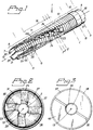
- FIGURE 1
- shows an anchoring element according to the invention, in an oblique side view and in perspective,
- FIGURE 2
- shows an end view of the object in Fig. 1, in a direction towards the inner end,
- FIGURE 3
- shows an end view of the object in Fig. 1, in a direction towards the outer end, and
- FIGURE 4
- shows sketches of a number of sections A - H perpendicular to the rotational axis of the anchoring element illustrating different cross-sections of the object in Fig. 1.
- The drawings are not up to scale and only approximate in respect of dimensional relationships.
- The anchoring element 1 according to the invention shown in Fig. 1 is of pure titanium that had been worked in a lathe and has the approximate shape of a cylindric sleeve with a symmetrically centred through
bore 2. On its outside the mantle of the cylindric sleeve is provided withthreads 20 commencing adjacent to the one, inner end 7, and extending in direction of the other,outer end 8, said threads covering the major part of the mantle, except for a narrow zone 9 having a width of about one thread pitch and a comparativelywider zone 10 adjacent toouter end 8. The portion of the cylinder mantle provided with outer threads comprises two sections, one non-segmented section 12 (shown in fig 4C) bordering the widerouter end zone 10, and asection 11 divided into four segments in the longitudinal direction of the element (shown in Figs. 4D to 4H) extending between the non-segmentedsection 12 and the narrow inner end zone 9 segmented in the same way as segmentedsection 11. - Segmentation of the inner end zone 9 and the
section 11 bordering threreon into foursegments slits centre bore 2.Slits centre axis 13 of the cylinder bore and haveparallel side walls 41, 42 and open ends coinciding with the inner end 7 of the element.Slits portion 11 and non-segmentedportion 12. The ratio of pitch ofslits exterior threads 20 is about 100 : 1, each ofslits slits segments - Segmentation of anchoring element 1 is complete only in one portion extending from the inner end 7 in direction of the
outer end 8 and bordering a partially segmented portion 16 (shown in Fig. 4D, 4E, 4F) comprising the remaining part of the segmented section. The partial segmentation is due to material bridges 23 (section through such a bridge is shown in Fig. 4E) connectingsegments centre axis 13, extends frombore 2 outwards in radial direction, having a thickness in this direction of about a fourth of the radial thickness of the threaded cylinder wall of anchoring element 1 nearbridges 23. Eachbridge 23 is segmented by circular holes (shown in section in Fig. 4D, 4F) with a diameter corresponding to the width ofslits bridges 23 thereby assume the shape of spiral notches or grooves. Groups of fourholes 24, one each for eachslit centre axis 13. For reasons of comprehensiveness onlymaterial bridge 23 connectingsegments - Bore 1 of anchoring
sleeve 2 widens conically (shown in section in Fig. 4G, 4H) towards the inner end 7 under formation triangularcone mantle segments inner end edge 31 formed by intersection of the cone by the outer wall of the cylinder mantle. In a section near inner end 7 the outer mantle is bevelled, such as to make the axial width ofexternal threads 20 to successively decrease in direction towards the inner end 7; said section comprises the aforementioned narrow zone 9 near the inner end 7 and some furtherouter threads 20. - Dissection of
slits outer threads 20 is such as to form sharp edges or rims 25 causing ablation of bone shavings during screwing-on. The material removed by ablation is received by the cavity formed by the conical widening at inner end 7 and byslits slits outer threads 20, the bone shavings inslits outer end 8 of element 1 during screwing-on of the anchoring element. This avoids tissue compression and local accumulation of material. By reason of the wall thickness near inner end 7 being comparatively small a certain spring action is obtained in radial direction; this facilitates screwing-on and, at the same time, decreases the stress at the inner end, particularly at functional loads.Brigdes 23 conteract deformation in tangential direction of anchoring element 1segments bore 2 and slits 3, 4, 5, 6 facing the free bone wall. - This communication is of importance, i.a., if factors promoting ingrowth of tissue or antibiotics are to be introduced from the outer end through
bore 2 after implant of the element. Anchoring after integration by the healing process thereby is also strengthened besides a communication channel for bone marrow and anchoring bones being obtained. - The
wide zone 10 of anchoring element 1, lacking threads and located adjacent toouter end 8 of element 1 has an annular flange 37 (shown in section in Fig 4B) bordering the threaded but not segmentedmantle portion 12, and an end portion 38 (shown in section in Fig. 4A) with reduced diameter borderingring flange 37. In a portion extending fromouter end 8 in direction of inner end 7bore 2 is provided withinternal threads 39 for fixation of a prosthesis or a part of a prosthesis. Aslot 30 in theouter end wall 40 serves for screwing-on of anchoring element 1 and as a counterstay if a prosthesis or a part of a prosthesis is to be mounted on element 1, for example by screwing-on a screwing means of the prosthesis or the prosthesis element intointernal threads 39. For the rest the outer end of the anchoring element is designed in a traditional way to obtain optimal fixation of the prosthesis or prosthetic element. - Slits with circular geometry and thus deeply cut into the material are appropriately arranged in the inner portion of the fixture the further outwards one is moving (if a greater extent of stiffness is desired), since the circles can be moved towards the periphery.
- Implantation of the anchoring element proposed according to the invention may, for instance, be carried out in the following way:
- In surgical implantation of the anchoring element a hole is made in the bone selected as anchoring site by use of a drill having essentially the same diameter as
inner diameter 20 of the exterior threads, said hole being made to a depth that is somewhat, but not much, larger than the distance between inner end 7 of element 1 andring flange 37. Thereafter the anchoring element is screwed into the bore while simultaneously removing bone material by ablation and formation of threads in the bone material. Anchoring element 1 is allowed to be integrated by the healing process during a period of time of from 2 to 6 months to achieve permanent anchoring, i.e. osseointegration. Thereafter the outer end of anchoring element 1 is exposed and the prosthesis or part of a prosthesis is mounted thereon. The thus mounted prosthesis will be able to bear loads right from the start.
Claims (22)
- In an essentially rotationally symmetric anchoring element for supporting prostheses or parts thereof, provided with external threads on the major part of its outside and arranged for connection at its outer end portion to said prostheses or parts thereof, and for insertion and anchoring in bone tissue by its opposite inner end portion, wherein at least one slit with cutting edges extends from the inner end in direction of the outer end portion, charcterized in that the anchoring element is provided with a centred through bore and that the slit is arranged in spiral form around the longitudinal axis of the anchoring element and extends over at least the major part of the outer wall of the element, said major part being provided with external threads, the chirality of the slit being the same as that of the outer threads.
- The anchoring element as claimd in claim 1, wherein the wall thickness of the element progressively decreases over a portion near the inner end and in direction towards the inner end.
- The anchoring element as claimd in claim 1 or 2, wherein a bridge of material is arranged between the walls of the slit and along a slit portion extending from the closed end of the slit, said bridge of material being penetrated by at least one hole, the inner wall of said bridge being delimited by the centred bore and the thickness of the bridge of material being substantially smaller than the wall thickness of the portion of the element extending in radial direction from the bridge of material.
- The anchoring element as claimd in claim 1 or 3, wherein the lateral walls of the slit are plane-parallel in respect to each other and that the hole or holes penetrating the bridge of material are prefereably circular, the diameter of said holes being substantially similar to the slit width.
- The anchoring element as claimd in claim 4, wherein in that the hole or holes have any other appropriate form, e.g. are oval.
- The anchoring element as claimed in any of claims 1 to 4, wherein the centred bore of the element widens in direction of the inner end of the element 1.
- The anchoring element as claimed in claim 6, wherein the the widening is substantially conical.
- The anchoring element as claimed in claim 6 or 7, wherein the anchoring element lacks bridges between the spiral slits in its portion widening in direction of the inner end of the element.
- The anchoring element as claimed in any of claims 1 to 7, wherein the inner end of the element has the form of an intersected annular edge, the radius of which substantially corresponds to the inner diameter of the external threads.
- The anchoring element as claimed in any of claims 1 to 9, wherein a number of spiral slits are arranged.
- The anchoring element as claimed in any of claims 1 to 10, wherein the number of spiral slits is two or three or a multiple of two, the slits in each pair of slits being arranged opposite to each other in respect of the centre bore axis and all slits positioned adjacent to each other being equidistant in all intersectional planes perpendicular to said axis.
- The anchoring element as claimed in claim 11, wherein the area occupied by slits in said portion of the anchoring element provided with slits is between 15 and 50 %.
- The anchoring element as claimed in any of claims 1 to 12, wherein the outer wall portion bordering the inner end lacks external threads.
- The anchoring element as claimed in any of claims 1 to 13, wherein its inner end portion is somewhat radially resilient.
- The anchoring element according to any preceding claim, wherein the fixation means for a prosthesis or a part of a prosthesis comprise internal threads arranged in the centred bore at the outer end portion of the anchoring element.
- The anchoring element according to any preceding claim, wherein the element also has a bore in its outer end portion, said bore tilting in respect of the centre axis by an angle β of between 25 and 65° to provide for passage of a nerve or a feeding means or similar.
- The anchoring element according to any preceding claim, wherein the ratio between the pitch of exterior threads and the pitch of each spiral groove is between 20:1 and 500: 1, preferably about 100:1.
- The anchoring element according to any preceding claim, wherein the element, at least in its parts being in contact with tissue upon implantation, is of titanium or other tissue-friendly material and that the element, at least in regard of the portion of its surface having tissue contact upon implantation, has a micropitted surface with a the pit diameter of between 10 and 1 000 nm, preferably between 10 - 300 nm.
- The use of the anchoring element according to any preceding claim for supporting prostheses or parts thereof in bone tissue.
- A method for anchoring an anchoring element for prostheses or parts of prostheses in bone tissue, said anchoring element having a hollow centre and being provided with external threads and self-tapping means, said method comprising- production of a hole in bone tissue, the diameter of said hole approximately corresponding to the inner diameter of the external threads of the anchoring element, said hole having a length adapted to the insertion depth of the element,- insertion of the element into the hole by self-tapping screwing-on while removing bone material by ablation and thereby forming threads in the bone material, said threads corresponding to the external threads of the anchoring element, whereby the removed bone material is received by one or several grooves provided in the outer wall of the anchoring element and is transported in the grooves in the direction of the outer end portion of the anchoring element, and anchoring the element in the bone by cooperation of its external threads with the threads cut into the bone tissue,- fixation of a prosthesis or a part of a prosthesis to the outer end of the anchoring element, said fixation being carried out in direct connection with the implantation of the element or a short time thereafter.
- A method according to claim 20, wherein the element is inserted into the hole made in bone tissue by a guide element passing through the centred bore.
- A method according to claim 20, further comprising
- post-implantation supply of pharmacologically active agents, such as agents promoting integration by the healing process, bactericides, bone marrow, etc., through the centred bore of the anchoring element to the bone tissue area provided with the hole for implantation of the element.
Applications Claiming Priority (2)
| Application Number | Priority Date | Filing Date | Title |
|---|---|---|---|
| SE9203181A SE510158C2 (en) | 1992-10-29 | 1992-10-29 | Anchorage elements for supporting prostheses and the use of such anchorage elements for fixing dentures |
| SE9203181 | 1992-10-29 |
Publications (3)
| Publication Number | Publication Date |
|---|---|
| EP0595782A2 true EP0595782A2 (en) | 1994-05-04 |
| EP0595782A3 EP0595782A3 (en) | 1994-08-24 |
| EP0595782B1 EP0595782B1 (en) | 1998-06-17 |
Family
ID=20387609
Family Applications (1)
| Application Number | Title | Priority Date | Filing Date |
|---|---|---|---|
| EP93850201A Expired - Lifetime EP0595782B1 (en) | 1992-10-29 | 1993-10-27 | Anchoring element supporting prostheses or a joint mechanism for a reconstructed joint |
Country Status (22)
| Country | Link |
|---|---|
| US (2) | US5735898A (en) |
| EP (1) | EP0595782B1 (en) |
| JP (1) | JP3737135B2 (en) |
| KR (1) | KR960015437B1 (en) |
| CN (1) | CN1091585C (en) |
| AT (1) | ATE167382T1 (en) |
| AU (1) | AU673380B2 (en) |
| BR (1) | BR9304406A (en) |
| CA (1) | CA2109244C (en) |
| CZ (1) | CZ284323B6 (en) |
| DE (1) | DE69319204T2 (en) |
| DK (1) | DK0595782T3 (en) |
| ES (1) | ES2118928T3 (en) |
| FI (1) | FI111330B (en) |
| HU (1) | HU216769B (en) |
| MX (1) | MX9306685A (en) |
| NO (1) | NO300444B1 (en) |
| PL (1) | PL172572B1 (en) |
| RU (1) | RU2111718C1 (en) |
| SE (1) | SE510158C2 (en) |
| TW (1) | TW340042B (en) |
| ZA (1) | ZA938044B (en) |
Cited By (13)
| Publication number | Priority date | Publication date | Assignee | Title |
|---|---|---|---|---|
| GB2294399A (en) * | 1994-10-28 | 1996-05-01 | Jbs Sa | Hollow bone-screw and sealing member for stabilising vertebrae |
| WO1997025939A1 (en) * | 1996-01-19 | 1997-07-24 | Astra Aktiebolag | Fixture and prosthesis including the same |
| FR2744010A1 (en) * | 1995-12-28 | 1997-08-01 | Martin Jean Jacques | Osseous implant manufacturing procedure, for e.g. osteosynthetic screws or tibial fixation plates etc |
| EP0808618A2 (en) * | 1996-05-24 | 1997-11-26 | Howmedica Inc. | Asymmetric hip stem |
| EP0826343A2 (en) * | 1994-08-15 | 1998-03-04 | Shedrick D. Jones | Method and apparatus for embedding an implant in bone tissue |
| US6129763A (en) * | 1996-09-13 | 2000-10-10 | Chauvin; Jean-Luc | Expandable osteosynthesis cage |
| WO2005077287A1 (en) * | 2004-02-11 | 2005-08-25 | Osteomed L.P. | Conical, threaded subtalar implant |
| CN102144938A (en) * | 2011-04-13 | 2011-08-10 | 初海滨 | Bone screw |
| WO2014165194A1 (en) | 2013-03-13 | 2014-10-09 | Blackstone Medical, Inc. | Pedicle screw with reverse spiral cut and methods thereof |
| US9707095B2 (en) | 2014-06-04 | 2017-07-18 | Wenzel Spine, Inc. | Bilaterally expanding intervertebral body fusion device |
| EP3808296A1 (en) | 2019-10-17 | 2021-04-21 | Heraeus Medical GmbH | Device for local application of and / or for rinsing with fluids |
| US11219531B2 (en) | 2019-04-10 | 2022-01-11 | Wenzel Spine, Inc. | Rotatable intervertebral spacing implant |
| US11938029B2 (en) | 2015-10-26 | 2024-03-26 | Leon E. POPOVITZ | Circulation replenishing joint implant |
Families Citing this family (207)
| Publication number | Priority date | Publication date | Assignee | Title |
|---|---|---|---|---|
| SE9303726D0 (en) * | 1992-11-26 | 1993-11-11 | Medevelop Ab | Anchoring element for anchorage in bone tissue |
| SE9301405D0 (en) * | 1993-04-27 | 1993-04-27 | Medevelop Ab | BEFORE IMPLANTATION IN WEAVEN PROVIDED, MAINLY ROTATION SYMETRICALLY TRAINED ANCHORING ORGANIZATION, CONDUCTING PROTESTS OR DIFFICULTLY, ANCHORING DEVICE COMPLETED FOR APPLICATION OF SUFFICIENT ANCHORING |
| EP1430843B1 (en) * | 1996-08-26 | 2007-10-17 | Shedrick D. Jones | Drill apparatus for embedding an implant in bone |
| DK1105058T3 (en) * | 1998-08-21 | 2002-10-14 | Synthes Ag | Self-cutting hollow cylindrical bone anchoring element |
| US6572655B1 (en) * | 1998-08-26 | 2003-06-03 | Lanny L. Johnson | Method for securing a prosthesis component to bone |
| WO2000032125A1 (en) | 1998-11-26 | 2000-06-08 | Synthes Ag Chur | Screw |
| ATE324072T1 (en) | 1998-12-30 | 2006-05-15 | Ethicon Inc | THREAD SECURING DEVICE |
| US6210376B1 (en) | 1999-04-08 | 2001-04-03 | New York University | Cannulated delivery pin |
| US6048343A (en) * | 1999-06-02 | 2000-04-11 | Mathis; John M. | Bone screw system |
| US6517542B1 (en) * | 1999-08-04 | 2003-02-11 | The Cleveland Clinic Foundation | Bone anchoring system |
| DE59913637D1 (en) * | 1999-09-24 | 2006-08-10 | Link Waldemar Gmbh Co | Alloplastic replacement for a long bone |
| US7887551B2 (en) * | 1999-12-02 | 2011-02-15 | Smith & Nephew, Inc. | Soft tissue attachment and repair |
| US7153312B1 (en) * | 1999-12-02 | 2006-12-26 | Smith & Nephew Inc. | Closure device and method for tissue repair |
| JP2003530946A (en) | 2000-04-20 | 2003-10-21 | ジンテーズ アクチエンゲゼルシャフト クール | Device for implant fixation on or in bone |
| DE10055891A1 (en) * | 2000-11-10 | 2002-06-06 | Biedermann Motech Gmbh | bone screw |
| US6743257B2 (en) * | 2000-12-19 | 2004-06-01 | Cortek, Inc. | Dynamic implanted intervertebral spacer |
| US6554865B2 (en) * | 2001-04-19 | 2003-04-29 | Wright Medical Technology, Inc. | Humeral stem with distal tri-slot |
| DE10129490A1 (en) * | 2001-06-21 | 2003-01-02 | Helmut Mueckter | Implantable screw for stabilization of joint or bone fracture, has flexible shaft which interconnects proximal head portion and distal insertion portion of elongated screw body |
| US20030149436A1 (en) * | 2002-02-04 | 2003-08-07 | Mcdowell Charles L. | Fixation and compression fastener assembly for bone fractures |
| US6875215B2 (en) * | 2002-02-15 | 2005-04-05 | John Stanley Taras | Distraction pin for fracture fixation |
| US20030176868A1 (en) * | 2002-02-22 | 2003-09-18 | Pepper John R. | Long bone reaming apparatus and method |
| WO2004002344A1 (en) * | 2002-06-26 | 2004-01-08 | Synthes Ag Chur | Bone fixing element |
| US7338493B1 (en) | 2002-06-28 | 2008-03-04 | Biomet Manufacturing Corp. | Method and apparatus for cementing a screw anchor |
| US20050101961A1 (en) * | 2003-11-12 | 2005-05-12 | Huebner Randall J. | Bone screws |
| US7226422B2 (en) * | 2002-10-09 | 2007-06-05 | Cardiac Pacemakers, Inc. | Detection of congestion from monitoring patient response to a recumbent position |
| SE526682C2 (en) * | 2002-12-19 | 2005-10-25 | Medevelop Ab | Fixture for screwing in bone tissue |
| SE0203787L (en) * | 2002-12-19 | 2004-03-09 | Exopro L A | Fixture for anchoring in bone tissue |
| US9314235B2 (en) * | 2003-02-05 | 2016-04-19 | Smith & Nephew, Inc. | Tissue anchor and insertion tool |
| US20060200128A1 (en) * | 2003-04-04 | 2006-09-07 | Richard Mueller | Bone anchor |
| US7608097B2 (en) * | 2003-04-29 | 2009-10-27 | Millennium Medical Technologies | Bone screw with fluid delivery structure |
| US7250055B1 (en) | 2003-08-26 | 2007-07-31 | Biomet Manufacturing Corp. | Method and apparatus for cement delivering buttress pin |
| US7588588B2 (en) | 2003-10-21 | 2009-09-15 | Innovative Spinal Technologies | System and method for stabilizing of internal structures |
| US7618442B2 (en) * | 2003-10-21 | 2009-11-17 | Theken Spine, Llc | Implant assembly and method for use in an internal structure stabilization system |
| US7967826B2 (en) * | 2003-10-21 | 2011-06-28 | Theken Spine, Llc | Connector transfer tool for internal structure stabilization systems |
| US7699852B2 (en) * | 2003-11-19 | 2010-04-20 | Zimmer Spine, Inc. | Fenestrated bone tap and method |
| US7608092B1 (en) | 2004-02-20 | 2009-10-27 | Biomet Sports Medicince, LLC | Method and apparatus for performing meniscus repair |
| DE102004009429A1 (en) * | 2004-02-24 | 2005-09-22 | Biedermann Motech Gmbh | Bone anchoring element |
| KR100555566B1 (en) | 2004-06-01 | 2006-03-03 | 삼성전자주식회사 | Actuator latch system for disk drive |
| US7771428B2 (en) * | 2004-06-11 | 2010-08-10 | Synthes Usa, Llc | Intramedullary rod with spiraling flutes |
| US9949843B2 (en) | 2004-08-09 | 2018-04-24 | Si-Bone Inc. | Apparatus, systems, and methods for the fixation or fusion of bone |
| US20060036251A1 (en) * | 2004-08-09 | 2006-02-16 | Reiley Mark A | Systems and methods for the fixation or fusion of bone |
| US20070156241A1 (en) | 2004-08-09 | 2007-07-05 | Reiley Mark A | Systems and methods for the fixation or fusion of bone |
| US8388667B2 (en) | 2004-08-09 | 2013-03-05 | Si-Bone, Inc. | Systems and methods for the fixation or fusion of bone using compressive implants |
| US9662158B2 (en) | 2004-08-09 | 2017-05-30 | Si-Bone Inc. | Systems and methods for the fixation or fusion of bone at or near a sacroiliac joint |
| US20180228621A1 (en) | 2004-08-09 | 2018-08-16 | Mark A. Reiley | Apparatus, systems, and methods for the fixation or fusion of bone |
| US20060089647A1 (en) * | 2004-08-20 | 2006-04-27 | Culbert Brad S | Method and apparatus for delivering an agent |
| GB0419961D0 (en) * | 2004-09-08 | 2004-10-13 | Sudmann Einar | Prosthetic element |
| ATE397912T1 (en) * | 2004-10-11 | 2008-07-15 | Smm Medical Ab | ELECTROACTIVE COMPRESSION BANDAGE |
| US8118836B2 (en) | 2004-11-05 | 2012-02-21 | Biomet Sports Medicine, Llc | Method and apparatus for coupling soft tissue to a bone |
| US9801708B2 (en) | 2004-11-05 | 2017-10-31 | Biomet Sports Medicine, Llc | Method and apparatus for coupling soft tissue to a bone |
| US8298262B2 (en) | 2006-02-03 | 2012-10-30 | Biomet Sports Medicine, Llc | Method for tissue fixation |
| US8840645B2 (en) | 2004-11-05 | 2014-09-23 | Biomet Sports Medicine, Llc | Method and apparatus for coupling soft tissue to a bone |
| US7658751B2 (en) | 2006-09-29 | 2010-02-09 | Biomet Sports Medicine, Llc | Method for implanting soft tissue |
| US8128658B2 (en) | 2004-11-05 | 2012-03-06 | Biomet Sports Medicine, Llc | Method and apparatus for coupling soft tissue to bone |
| US7857830B2 (en) | 2006-02-03 | 2010-12-28 | Biomet Sports Medicine, Llc | Soft tissue repair and conduit device |
| US8137382B2 (en) | 2004-11-05 | 2012-03-20 | Biomet Sports Medicine, Llc | Method and apparatus for coupling anatomical features |
| US8088130B2 (en) | 2006-02-03 | 2012-01-03 | Biomet Sports Medicine, Llc | Method and apparatus for coupling soft tissue to a bone |
| US7909851B2 (en) | 2006-02-03 | 2011-03-22 | Biomet Sports Medicine, Llc | Soft tissue repair device and associated methods |
| US7905904B2 (en) | 2006-02-03 | 2011-03-15 | Biomet Sports Medicine, Llc | Soft tissue repair device and associated methods |
| US8303604B2 (en) | 2004-11-05 | 2012-11-06 | Biomet Sports Medicine, Llc | Soft tissue repair device and method |
| US8361113B2 (en) | 2006-02-03 | 2013-01-29 | Biomet Sports Medicine, Llc | Method and apparatus for coupling soft tissue to a bone |
| US9017381B2 (en) | 2007-04-10 | 2015-04-28 | Biomet Sports Medicine, Llc | Adjustable knotless loops |
| US20060189993A1 (en) | 2004-11-09 | 2006-08-24 | Arthrotek, Inc. | Soft tissue conduit device |
| US7905903B2 (en) | 2006-02-03 | 2011-03-15 | Biomet Sports Medicine, Llc | Method for tissue fixation |
| US20060190042A1 (en) * | 2004-11-05 | 2006-08-24 | Arthrotek, Inc. | Tissue repair assembly |
| US7749250B2 (en) | 2006-02-03 | 2010-07-06 | Biomet Sports Medicine, Llc | Soft tissue repair assembly and associated method |
| US7914539B2 (en) | 2004-11-09 | 2011-03-29 | Biomet Sports Medicine, Llc | Tissue fixation device |
| US8998949B2 (en) | 2004-11-09 | 2015-04-07 | Biomet Sports Medicine, Llc | Soft tissue conduit device |
| US8034090B2 (en) * | 2004-11-09 | 2011-10-11 | Biomet Sports Medicine, Llc | Tissue fixation device |
| US7569061B2 (en) * | 2004-11-16 | 2009-08-04 | Innovative Spinal Technologies, Inc. | Off-axis anchor guidance system |
| US20060155286A1 (en) * | 2005-01-11 | 2006-07-13 | Chao-Jan Wang | Bone securing bolt |
| US8197523B2 (en) | 2005-02-15 | 2012-06-12 | Apex Biomedical Company, Llc | Bone screw for positive locking but flexible engagement to a bone |
| US8740955B2 (en) | 2005-02-15 | 2014-06-03 | Zimmer, Inc. | Bone screw with multiple thread profiles for far cortical locking and flexible engagement to a bone |
| SE528545C2 (en) * | 2005-02-16 | 2006-12-12 | Swemac Orthopaedics Ab | Articulated prosthesis and screw tools to apply parts of the same |
| DE102005008779B3 (en) * | 2005-02-25 | 2006-11-23 | Sfs Intec Holding Ag | threaded element |
| US20060217717A1 (en) * | 2005-03-24 | 2006-09-28 | Dale Whipple | Methods and devices for stabilizing a bone anchor |
| US20090062868A1 (en) * | 2005-04-04 | 2009-03-05 | Zimmer Gmbh | Pedicle screw |
| US7749259B2 (en) * | 2005-04-08 | 2010-07-06 | Warsaw Orthopedic, Inc. | Slotted screw for use with a vertebral member |
| US20070083236A1 (en) * | 2005-06-24 | 2007-04-12 | Smith & Nephew, Inc. | Methods and devices for tissue repair |
| US20060293709A1 (en) | 2005-06-24 | 2006-12-28 | Bojarski Raymond A | Tissue repair device |
| KR101145415B1 (en) * | 2005-07-08 | 2012-05-15 | 비이더만 모테크 게엠베하 & 코. 카게 | Bone Anchoring Element |
| ES2318391T3 (en) * | 2005-08-05 | 2009-05-01 | Biedermann Motech Gmbh | OSEO ANCHORAGE ELEMENT. |
| US20070161985A1 (en) * | 2005-12-05 | 2007-07-12 | Kentomia, Llc . | Screws configured to engage bones, and methods of attaching implants to skeletal regions |
| CA2636715A1 (en) | 2006-01-13 | 2007-07-19 | Smm Medical Ab | Device, system and method for compression treatment of a body part |
| US10517587B2 (en) | 2006-02-03 | 2019-12-31 | Biomet Sports Medicine, Llc | Method and apparatus for forming a self-locking adjustable loop |
| US11259792B2 (en) | 2006-02-03 | 2022-03-01 | Biomet Sports Medicine, Llc | Method and apparatus for coupling anatomical features |
| US9149267B2 (en) | 2006-02-03 | 2015-10-06 | Biomet Sports Medicine, Llc | Method and apparatus for coupling soft tissue to a bone |
| US9271713B2 (en) | 2006-02-03 | 2016-03-01 | Biomet Sports Medicine, Llc | Method and apparatus for tensioning a suture |
| US8968364B2 (en) | 2006-02-03 | 2015-03-03 | Biomet Sports Medicine, Llc | Method and apparatus for fixation of an ACL graft |
| US8562645B2 (en) | 2006-09-29 | 2013-10-22 | Biomet Sports Medicine, Llc | Method and apparatus for forming a self-locking adjustable loop |
| US8652172B2 (en) | 2006-02-03 | 2014-02-18 | Biomet Sports Medicine, Llc | Flexible anchors for tissue fixation |
| US8652171B2 (en) | 2006-02-03 | 2014-02-18 | Biomet Sports Medicine, Llc | Method and apparatus for soft tissue fixation |
| US9078644B2 (en) | 2006-09-29 | 2015-07-14 | Biomet Sports Medicine, Llc | Fracture fixation device |
| US8597327B2 (en) | 2006-02-03 | 2013-12-03 | Biomet Manufacturing, Llc | Method and apparatus for sternal closure |
| US9538998B2 (en) | 2006-02-03 | 2017-01-10 | Biomet Sports Medicine, Llc | Method and apparatus for fracture fixation |
| US8936621B2 (en) | 2006-02-03 | 2015-01-20 | Biomet Sports Medicine, Llc | Method and apparatus for forming a self-locking adjustable loop |
| US8251998B2 (en) | 2006-08-16 | 2012-08-28 | Biomet Sports Medicine, Llc | Chondral defect repair |
| US11311287B2 (en) | 2006-02-03 | 2022-04-26 | Biomet Sports Medicine, Llc | Method for tissue fixation |
| US8771352B2 (en) | 2011-05-17 | 2014-07-08 | Biomet Sports Medicine, Llc | Method and apparatus for tibial fixation of an ACL graft |
| US8506597B2 (en) | 2011-10-25 | 2013-08-13 | Biomet Sports Medicine, Llc | Method and apparatus for interosseous membrane reconstruction |
| US8562647B2 (en) | 2006-09-29 | 2013-10-22 | Biomet Sports Medicine, Llc | Method and apparatus for securing soft tissue to bone |
| US8574235B2 (en) | 2006-02-03 | 2013-11-05 | Biomet Sports Medicine, Llc | Method for trochanteric reattachment |
| US8801783B2 (en) | 2006-09-29 | 2014-08-12 | Biomet Sports Medicine, Llc | Prosthetic ligament system for knee joint |
| US7959650B2 (en) | 2006-09-29 | 2011-06-14 | Biomet Sports Medicine, Llc | Adjustable knotless loops |
| ES2313472T3 (en) | 2006-02-23 | 2009-03-01 | Biedermann Motech Gmbh | OSEO ANCHORAGE DEVICE. |
| US20070225806A1 (en) * | 2006-03-24 | 2007-09-27 | Sdgi Holdings, Inc. | Arthroplasty device |
| US8500818B2 (en) | 2006-09-29 | 2013-08-06 | Biomet Manufacturing, Llc | Knee prosthesis assembly with ligament link |
| US11259794B2 (en) | 2006-09-29 | 2022-03-01 | Biomet Sports Medicine, Llc | Method for implanting soft tissue |
| US9918826B2 (en) | 2006-09-29 | 2018-03-20 | Biomet Sports Medicine, Llc | Scaffold for spring ligament repair |
| US8672969B2 (en) | 2006-09-29 | 2014-03-18 | Biomet Sports Medicine, Llc | Fracture fixation device |
| US8221479B2 (en) * | 2007-01-19 | 2012-07-17 | Pbj, Llc | Orthopedic screw insert |
| US8398690B2 (en) * | 2007-02-07 | 2013-03-19 | Apex Biomedical Company, Llc | Rotationally asymmetric bone screw |
| US10758283B2 (en) * | 2016-08-11 | 2020-09-01 | Mighty Oak Medical, Inc. | Fixation devices having fenestrations and methods for using the same |
| US8974505B2 (en) * | 2008-06-16 | 2015-03-10 | Anna G. U. Sawa | Venting/pressure adjustment to aid in delivery of material into an anatomic region via a cannula |
| DE102008053104A1 (en) * | 2008-07-21 | 2010-01-28 | Grabosch, Reinhold, Dr. | Implant for insertion in the jaw and prosthetic abutments |
| WO2010051386A1 (en) | 2008-10-30 | 2010-05-06 | Depuy Spine, Inc. | Systems and methods for delivering bone cement to a bone anchor |
| JP5291719B2 (en) * | 2008-10-31 | 2013-09-18 | 株式会社ロバート・リード商会 | Bone fixation member and femoral fixation system |
| US9468465B2 (en) | 2009-02-19 | 2016-10-18 | Nextremity Solutions, Inc. | Reversible bone coupling device and method |
| US9072562B2 (en) | 2009-02-19 | 2015-07-07 | Nextremity Solutions, Inc. | Bone joining device, kit and method |
| BRPI1008295A2 (en) * | 2009-02-19 | 2016-03-15 | Nextremity Solutions Llc | bone joint apparatus and method |
| BRMU8900506U2 (en) * | 2009-03-12 | 2010-11-30 | Geninho Thome | fixation screw for prosthetic components in implant dentistry |
| EP2421453A2 (en) * | 2009-04-20 | 2012-02-29 | Osteo Innovations Llc | System and method for self filling bone screws |
| US8343227B2 (en) | 2009-05-28 | 2013-01-01 | Biomet Manufacturing Corp. | Knee prosthesis assembly with ligament link |
| US9095444B2 (en) | 2009-07-24 | 2015-08-04 | Warsaw Orthopedic, Inc. | Implant with an interference fit fastener |
| US8574273B2 (en) * | 2009-09-09 | 2013-11-05 | Innovision, Inc. | Bone screws and methods of use thereof |
| IL201902A (en) | 2009-11-03 | 2012-12-31 | Ben-Zion Karmon | Dental implant |
| US20110112436A1 (en) * | 2009-11-06 | 2011-05-12 | SpineSmith Partners, LP | Distraction pins for fluid aspiration |
| ES2456317T3 (en) * | 2010-02-26 | 2014-04-22 | Biedermann Technologies Gmbh & Co. Kg | Bone screw |
| US9138219B2 (en) | 2010-12-29 | 2015-09-22 | Tarsus Medical Inc. | Methods and devices for treating a syndesmosis injury |
| US9211153B2 (en) | 2011-01-04 | 2015-12-15 | DePuy Synthes Products, Inc. | Expansion screw bone tamp |
| SE535749C2 (en) * | 2011-05-09 | 2012-12-04 | Akoustos Ab | Fixing arrangement with two sub-parts for holding together two constructions and tools for the arrangement |
| CN102920517A (en) * | 2011-08-08 | 2013-02-13 | 国维联合科技股份有限公司 | Artificial tooth implant fixing structure |
| US9155580B2 (en) | 2011-08-25 | 2015-10-13 | Medos International Sarl | Multi-threaded cannulated bone anchors |
| US9357991B2 (en) | 2011-11-03 | 2016-06-07 | Biomet Sports Medicine, Llc | Method and apparatus for stitching tendons |
| US9370350B2 (en) | 2011-11-10 | 2016-06-21 | Biomet Sports Medicine, Llc | Apparatus for coupling soft tissue to a bone |
| US9357992B2 (en) | 2011-11-10 | 2016-06-07 | Biomet Sports Medicine, Llc | Method for coupling soft tissue to a bone |
| US9381013B2 (en) | 2011-11-10 | 2016-07-05 | Biomet Sports Medicine, Llc | Method for coupling soft tissue to a bone |
| US9259217B2 (en) | 2012-01-03 | 2016-02-16 | Biomet Manufacturing, Llc | Suture Button |
| US9687285B2 (en) | 2012-01-25 | 2017-06-27 | Spectrum Spine Ip Holdings, Llc | Fenestrated bone screws and methods of bone fastening and stabilization |
| KR20140147834A (en) | 2012-03-09 | 2014-12-30 | 에스아이-본 인코포레이티드 | Integrated implant |
| US10363140B2 (en) | 2012-03-09 | 2019-07-30 | Si-Bone Inc. | Systems, device, and methods for joint fusion |
| WO2013166496A1 (en) | 2012-05-04 | 2013-11-07 | Si-Bone Inc. | Fenestrated implant |
| US9295488B2 (en) | 2012-08-09 | 2016-03-29 | Wilson T. Asfora | Joint fusion |
| US20140058461A1 (en) * | 2012-08-27 | 2014-02-27 | Michael Black | Fenestrated Bone Screw |
| US9757119B2 (en) | 2013-03-08 | 2017-09-12 | Biomet Sports Medicine, Llc | Visual aid for identifying suture limbs arthroscopically |
| US9918827B2 (en) | 2013-03-14 | 2018-03-20 | Biomet Sports Medicine, Llc | Scaffold for spring ligament repair |
| US20140277536A1 (en) * | 2013-03-14 | 2014-09-18 | Filip Leszko | Orthopaedic knee prosthesis having stem components with a varying number of slots |
| US9936983B2 (en) | 2013-03-15 | 2018-04-10 | Si-Bone Inc. | Implants for spinal fixation or fusion |
| AU2014237911B2 (en) | 2013-03-15 | 2018-02-15 | Innovision, Inc. | Bone screws and methods of use thereof |
| US11147688B2 (en) | 2013-10-15 | 2021-10-19 | Si-Bone Inc. | Implant placement |
| US9839448B2 (en) | 2013-10-15 | 2017-12-12 | Si-Bone Inc. | Implant placement |
| CN104665905B (en) | 2013-11-26 | 2018-04-06 | 财团法人工业技术研究院 | Bionic fixing device |
| CN104665913B (en) * | 2013-11-26 | 2017-06-06 | 财团法人工业技术研究院 | Bionic fixing device and pulling-out device thereof |
| CN104665906B (en) | 2013-11-26 | 2017-09-08 | 财团法人工业技术研究院 | Bionic fixing device |
| US10136886B2 (en) | 2013-12-20 | 2018-11-27 | Biomet Sports Medicine, Llc | Knotless soft tissue devices and techniques |
| WO2015095965A1 (en) * | 2013-12-23 | 2015-07-02 | The University Of Western Ontario | Anchor device |
| US9615822B2 (en) | 2014-05-30 | 2017-04-11 | Biomet Sports Medicine, Llc | Insertion tools and method for soft anchor |
| US9700291B2 (en) | 2014-06-03 | 2017-07-11 | Biomet Sports Medicine, Llc | Capsule retractor |
| US10045803B2 (en) | 2014-07-03 | 2018-08-14 | Mayo Foundation For Medical Education And Research | Sacroiliac joint fusion screw and method |
| US10039543B2 (en) | 2014-08-22 | 2018-08-07 | Biomet Sports Medicine, Llc | Non-sliding soft anchor |
| US10166033B2 (en) | 2014-09-18 | 2019-01-01 | Si-Bone Inc. | Implants for bone fixation or fusion |
| ES2826600T3 (en) | 2014-09-18 | 2021-05-18 | Si Bone Inc | Matrix implant |
| US9955980B2 (en) | 2015-02-24 | 2018-05-01 | Biomet Sports Medicine, Llc | Anatomic soft tissue repair |
| US9974534B2 (en) | 2015-03-31 | 2018-05-22 | Biomet Sports Medicine, Llc | Suture anchor with soft anchor of electrospun fibers |
| US10376206B2 (en) | 2015-04-01 | 2019-08-13 | Si-Bone Inc. | Neuromonitoring systems and methods for bone fixation or fusion procedures |
| DE102015107056B4 (en) * | 2015-05-06 | 2021-04-01 | Syntellix Ag | Arthrodesis implant |
| CN106264803A (en) * | 2015-05-14 | 2017-01-04 | 中国人民解放军总医院 | Implanted justice refers to system |
| TWI587847B (en) | 2015-12-07 | 2017-06-21 | 財團法人工業技術研究院 | Implant device for osseous integration |
| USD783824S1 (en) | 2016-02-05 | 2017-04-11 | Silvio Franco Emanuelli | Root part for a dental implant |
| USD783826S1 (en) | 2016-02-05 | 2017-04-11 | Silvio Franco Emanuelli | Root part for a dental implant |
| USD783823S1 (en) | 2016-02-05 | 2017-04-11 | Silvio Franco Emanuelli | Post part for a dental implant |
| USD783822S1 (en) | 2016-02-05 | 2017-04-11 | Silvio Franco Emanuelli | Root part for a dental implant |
| USD785179S1 (en) | 2016-02-05 | 2017-04-25 | Silvio Franco Emanuelli | Post part for a dental implant |
| USD783825S1 (en) | 2016-02-05 | 2017-04-11 | Silvio Franco Emanuelli | Post part for a dental implant |
| US9833321B2 (en) | 2016-04-25 | 2017-12-05 | Imds Llc | Joint fusion instrumentation and methods |
| US10413332B2 (en) | 2016-04-25 | 2019-09-17 | Imds Llc | Joint fusion implant and methods |
| US10743890B2 (en) | 2016-08-11 | 2020-08-18 | Mighty Oak Medical, Inc. | Drill apparatus and surgical fixation devices and methods for using the same |
| CN106420032B (en) * | 2016-08-31 | 2019-07-26 | 苏州西脉新诚生物科技有限公司 | A kind of multiway fastening bone screws |
| US11918262B2 (en) * | 2017-03-30 | 2024-03-05 | K2M, Inc. | Fixation device and method of using the same |
| US11116519B2 (en) | 2017-09-26 | 2021-09-14 | Si-Bone Inc. | Systems and methods for decorticating the sacroiliac joint |
| USD850616S1 (en) | 2017-10-31 | 2019-06-04 | Sicage Llc | Parallel surgical guide spacer |
| US10631905B2 (en) | 2017-10-31 | 2020-04-28 | Sicage Llc | Bone cage with helically arranged fenestrations |
| USD847994S1 (en) | 2017-10-31 | 2019-05-07 | Sicage Llc | Bone screw |
| USD904615S1 (en) | 2017-10-31 | 2020-12-08 | Sicage Llc | Bone screw |
| USD847336S1 (en) | 2017-10-31 | 2019-04-30 | Sicage Llc | Parallel surgical guide spacer |
| US10792053B2 (en) | 2017-10-31 | 2020-10-06 | Sicage Llc | Press system for setting a surgical device |
| US10603054B2 (en) | 2017-10-31 | 2020-03-31 | Sicage Llc | Parallel guide for surgical implants |
| MA41535B1 (en) * | 2017-11-27 | 2019-10-31 | Mohamed Faoussi | Osteointegrated orthopedic implant intended for femoral amputations with short stumps |
| US10624626B2 (en) | 2018-06-04 | 2020-04-21 | West Gen Technologies, L.L.C. | Fixation device |
| RU2695623C1 (en) * | 2018-09-10 | 2019-07-24 | Сергей Сергеевич Горшков | Method for osteointegrated prosthesis implantation |
| US11160592B2 (en) | 2018-10-18 | 2021-11-02 | Biedermann Technologies Gmbh & Co. Kg | Method of using bone plate with polyaxial injection screws |
| US11660133B2 (en) | 2018-10-26 | 2023-05-30 | Zimmer, Inc. | Bone coupling device and method |
| AU2020223180A1 (en) | 2019-02-14 | 2021-07-22 | Si-Bone Inc. | Implants for spinal fixation and or fusion |
| US11369419B2 (en) | 2019-02-14 | 2022-06-28 | Si-Bone Inc. | Implants for spinal fixation and or fusion |
| USD935876S1 (en) * | 2019-05-07 | 2021-11-16 | Si-Restore Llc | Screw |
| USD927295S1 (en) * | 2019-05-07 | 2021-08-10 | RRR Sports LLC | Screw |
| USD907773S1 (en) | 2019-06-03 | 2021-01-12 | West Gen Technologies, L.L.C. | Fixation device cartridge |
| USD929586S1 (en) | 2019-06-03 | 2021-08-31 | West Gen Technologies, L.L.C. | Guide tool |
| USD944634S1 (en) | 2019-06-03 | 2022-03-01 | West Gen Technologies, L.L.C. | Fixation device |
| USD907772S1 (en) | 2019-06-03 | 2021-01-12 | West Gen Technologies, L.L.C. | Fixation device cartridge |
| US11123173B2 (en) | 2019-09-11 | 2021-09-21 | Gary A. Zwick | Implant comprising first and second sets of pillars for attaching a tendon or a ligament to a hard tissue |
| DE202019004770U1 (en) * | 2019-11-25 | 2021-03-01 | lsel GmbH & Co. KG | Self-tapping screw-in anchor sleeve |
| WO2021108590A1 (en) | 2019-11-27 | 2021-06-03 | Si-Bone, Inc. | Bone stabilizing implants and methods of placement across si joints |
| EP3831426A1 (en) | 2019-12-05 | 2021-06-09 | Heraeus Medical GmbH | Device for local application of pharmaceutical fluids |
| US11478260B2 (en) | 2020-07-17 | 2022-10-25 | Asfora Ip, Llc | Parallel guide for access needle |
| JP2023553120A (en) | 2020-12-09 | 2023-12-20 | エスアイ-ボーン・インコーポレイテッド | Sacroiliac joint stabilization implants and implant methods |
| US20230025644A1 (en) * | 2021-07-21 | 2023-01-26 | Choice Spine, Llc | Bone Screws |
Citations (3)
| Publication number | Priority date | Publication date | Assignee | Title |
|---|---|---|---|---|
| DE3027138A1 (en) * | 1980-05-28 | 1981-12-03 | Institut Straumann Ag, Waldenburg | DEVICE WITH AN IMPLANT AND ATTACHING ITEM TO SCREWS USING A BONE AND DEVICE FOR CONNECTING TWO BONE PIECES SEPARATED BY A GAP |
| EP0454646A1 (en) * | 1990-04-26 | 1991-10-30 | Medevelop Ab | Joint reconstruction system especially for wrist joints |
| US5108443A (en) * | 1989-04-25 | 1992-04-28 | Medevelop Ab | Anchoring element for supporting a joint mechanism of a finger or other reconstructed joint |
Family Cites Families (23)
| Publication number | Priority date | Publication date | Assignee | Title |
|---|---|---|---|---|
| US45133A (en) * | 1864-11-22 | Improvement in screws | ||
| FR537101A (en) * | 1922-05-16 | |||
| US1232099A (en) * | 1917-01-18 | 1917-07-03 | Carl Schoenert | Thread-cutting tap. |
| US1708793A (en) * | 1927-10-07 | 1929-04-09 | Allan H Jones | Bolt, shaft, and the like |
| US2165011A (en) * | 1935-02-08 | 1939-07-04 | Rosenberg Heyman | Anchorage apparatus |
| US2387720A (en) * | 1944-06-26 | 1945-10-30 | Frank L Davis | Self-threading screw |
| US3240102A (en) * | 1964-02-24 | 1966-03-15 | Raymond P Sandor | Self-drilling sheet metal screw |
| DE2256938C3 (en) * | 1972-11-21 | 1985-10-03 | Upat Gmbh & Co, 7830 Emmendingen | Insert sleeve for plaster walls or the like. |
| US4537185A (en) * | 1983-06-10 | 1985-08-27 | Denis P. Stednitz | Cannulated fixation screw |
| CH671150A5 (en) * | 1986-10-13 | 1989-08-15 | Jaquet Orthopedie | |
| IL80705A0 (en) * | 1985-11-28 | 1987-02-27 | Jaquet Orthopedie | Transcutaneous pin for fixation of a bone part or fragment |
| US4712957A (en) * | 1985-12-11 | 1987-12-15 | Wayne Edwards | Adhesively secured fastener |
| US4842518A (en) * | 1986-09-04 | 1989-06-27 | Vent-Plant Corporation | Submergible screw-type dental implant and method of utilization |
| GB8625174D0 (en) * | 1986-10-21 | 1986-11-26 | Edwards Barry Noel | Dental prostheses |
| DE3640312A1 (en) * | 1986-11-26 | 1988-06-09 | Tox Duebel Werk | SPREADING DOWEL |
| FR2632029B1 (en) * | 1988-05-30 | 1990-09-07 | Surer Patrick | DEVICE FOR FIXING A WORKPIECE ON A SUPPORT, IN PARTICULAR OF AN IMPLANT ON A BONE |
| BE1002350A3 (en) * | 1988-08-02 | 1991-01-08 | Dury Georges Emile Ladislas | IMPLANT. |
| SE466936B (en) * | 1989-04-25 | 1992-05-04 | Branemark Per Ingvar | ANCHORING ELEMENT FOR PROCESSING |
| US4927421A (en) * | 1989-05-15 | 1990-05-22 | Marlowe Goble E | Process of endosteal fixation of a ligament |
| US5458638A (en) * | 1989-07-06 | 1995-10-17 | Spine-Tech, Inc. | Non-threaded spinal implant |
| US5004421A (en) * | 1990-07-27 | 1991-04-02 | Sargon Lazarof | Dental implant and method of using same |
| JPH0777693B2 (en) * | 1990-08-30 | 1995-08-23 | 出雲産業株式会社 | Tap |
| US5195891A (en) * | 1990-12-06 | 1993-03-23 | Sulc Josef M | Adjustable dental implant system |
-
1992
- 1992-10-29 SE SE9203181A patent/SE510158C2/en not_active IP Right Cessation
-
1993
- 1993-10-15 TW TW082108537A patent/TW340042B/en not_active IP Right Cessation
- 1993-10-25 KR KR1019930022219A patent/KR960015437B1/en not_active IP Right Cessation
- 1993-10-25 RU RU93048460A patent/RU2111718C1/en not_active IP Right Cessation
- 1993-10-26 CA CA002109244A patent/CA2109244C/en not_active Expired - Fee Related
- 1993-10-27 CZ CZ932288A patent/CZ284323B6/en not_active IP Right Cessation
- 1993-10-27 ES ES93850201T patent/ES2118928T3/en not_active Expired - Lifetime
- 1993-10-27 MX MX9306685A patent/MX9306685A/en unknown
- 1993-10-27 NO NO933875A patent/NO300444B1/en unknown
- 1993-10-27 EP EP93850201A patent/EP0595782B1/en not_active Expired - Lifetime
- 1993-10-27 AT AT93850201T patent/ATE167382T1/en not_active IP Right Cessation
- 1993-10-27 DE DE69319204T patent/DE69319204T2/en not_active Expired - Lifetime
- 1993-10-27 DK DK93850201T patent/DK0595782T3/en active
- 1993-10-28 HU HU9303068A patent/HU216769B/en not_active IP Right Cessation
- 1993-10-28 ZA ZA938044A patent/ZA938044B/en unknown
- 1993-10-28 AU AU50354/93A patent/AU673380B2/en not_active Ceased
- 1993-10-28 FI FI934779A patent/FI111330B/en not_active IP Right Cessation
- 1993-10-28 CN CN93120231A patent/CN1091585C/en not_active Expired - Fee Related
- 1993-10-29 PL PL93300895A patent/PL172572B1/en not_active IP Right Cessation
- 1993-10-29 BR BR9304406A patent/BR9304406A/en not_active IP Right Cessation
- 1993-10-29 JP JP27167193A patent/JP3737135B2/en not_active Expired - Fee Related
-
1996
- 1996-09-25 US US08/719,585 patent/US5735898A/en not_active Expired - Lifetime
- 1996-11-27 US US08/757,901 patent/US5725581A/en not_active Expired - Lifetime
Patent Citations (3)
| Publication number | Priority date | Publication date | Assignee | Title |
|---|---|---|---|---|
| DE3027138A1 (en) * | 1980-05-28 | 1981-12-03 | Institut Straumann Ag, Waldenburg | DEVICE WITH AN IMPLANT AND ATTACHING ITEM TO SCREWS USING A BONE AND DEVICE FOR CONNECTING TWO BONE PIECES SEPARATED BY A GAP |
| US5108443A (en) * | 1989-04-25 | 1992-04-28 | Medevelop Ab | Anchoring element for supporting a joint mechanism of a finger or other reconstructed joint |
| EP0454646A1 (en) * | 1990-04-26 | 1991-10-30 | Medevelop Ab | Joint reconstruction system especially for wrist joints |
Cited By (28)
| Publication number | Priority date | Publication date | Assignee | Title |
|---|---|---|---|---|
| EP0826343A2 (en) * | 1994-08-15 | 1998-03-04 | Shedrick D. Jones | Method and apparatus for embedding an implant in bone tissue |
| EP0826343A3 (en) * | 1994-08-15 | 1998-07-22 | Shedrick D. Jones | Method and apparatus for embedding an implant in bone tissue |
| GB2294399A (en) * | 1994-10-28 | 1996-05-01 | Jbs Sa | Hollow bone-screw and sealing member for stabilising vertebrae |
| GB2294399B (en) * | 1994-10-28 | 1999-03-24 | Jbs Sa | Bone Screw Devices |
| FR2744010A1 (en) * | 1995-12-28 | 1997-08-01 | Martin Jean Jacques | Osseous implant manufacturing procedure, for e.g. osteosynthetic screws or tibial fixation plates etc |
| AU723598B2 (en) * | 1996-01-19 | 2000-08-31 | Astra Aktiebolag | Fixture and prosthesis including the same |
| WO1997025939A1 (en) * | 1996-01-19 | 1997-07-24 | Astra Aktiebolag | Fixture and prosthesis including the same |
| US6610099B1 (en) | 1996-01-19 | 2003-08-26 | Astra Aktiebolag | Fixture and prosthesis including the same |
| EP0808618A3 (en) * | 1996-05-24 | 1999-03-10 | Howmedica Inc. | Asymmetric hip stem |
| US6102957A (en) * | 1996-05-24 | 2000-08-15 | Stryker Technlogies Corporation | Asymmetric hip stem |
| US6007581A (en) * | 1996-05-24 | 1999-12-28 | Stryker Technologies Corporation | Asymmetric hip stem |
| EP0808618A2 (en) * | 1996-05-24 | 1997-11-26 | Howmedica Inc. | Asymmetric hip stem |
| US6129763A (en) * | 1996-09-13 | 2000-10-10 | Chauvin; Jean-Luc | Expandable osteosynthesis cage |
| US6371989B1 (en) | 1996-09-13 | 2002-04-16 | Jean-Luc Chauvin | Method of providing proper vertebral spacing |
| WO2005077287A1 (en) * | 2004-02-11 | 2005-08-25 | Osteomed L.P. | Conical, threaded subtalar implant |
| US8628581B2 (en) | 2004-02-11 | 2014-01-14 | Osteomed Llc | Conical, threaded subtalar implant |
| CN102144938A (en) * | 2011-04-13 | 2011-08-10 | 初海滨 | Bone screw |
| EP3782561A1 (en) * | 2013-03-13 | 2021-02-24 | Blackstone Medical, Inc. | Pedicle screw with reverse spiral cut |
| WO2014165194A1 (en) | 2013-03-13 | 2014-10-09 | Blackstone Medical, Inc. | Pedicle screw with reverse spiral cut and methods thereof |
| EP2967582A4 (en) * | 2013-03-13 | 2016-10-05 | Blackstone Medical Inc | Pedicle screw with reverse spiral cut and methods thereof |
| AU2014248622B2 (en) * | 2013-03-13 | 2017-03-30 | Orthofix Us Llc | Pedicle screw with reverse spiral cut and methods thereof |
| US9636158B2 (en) | 2013-03-13 | 2017-05-02 | Blackstone Medical, Inc. | Pedicle screw with reverse spiral cut and methods thereof |
| US9707095B2 (en) | 2014-06-04 | 2017-07-18 | Wenzel Spine, Inc. | Bilaterally expanding intervertebral body fusion device |
| US10098756B2 (en) | 2014-06-04 | 2018-10-16 | Wenzel Spine, Inc. | Bilaterally expanding intervertebral body fusion device |
| US10945857B2 (en) | 2014-06-04 | 2021-03-16 | Wenzel Spine, Inc. | Bilaterally expanding intervertebral body fusion device |
| US11938029B2 (en) | 2015-10-26 | 2024-03-26 | Leon E. POPOVITZ | Circulation replenishing joint implant |
| US11219531B2 (en) | 2019-04-10 | 2022-01-11 | Wenzel Spine, Inc. | Rotatable intervertebral spacing implant |
| EP3808296A1 (en) | 2019-10-17 | 2021-04-21 | Heraeus Medical GmbH | Device for local application of and / or for rinsing with fluids |
Also Published As
Similar Documents
| Publication | Publication Date | Title |
|---|---|---|
| US5725581A (en) | Anchoring element supporting prostheses or a joint mechanism for a reconstructed joint | |
| EP1223894B1 (en) | Implant | |
| EP0237505B1 (en) | Anchoring member for permanent anchorage in bone tissue | |
| EP1120096B1 (en) | Fixture for a hip joint prosthesis | |
| US5176709A (en) | Method for inserting an anchoring element within a bone | |
| JP4658970B2 (en) | Prosthesis for surface replacement in the ball region of ball joints | |
| CA1334884C (en) | Anchoring element for supporting a joint mechanism of a finger or other reconstructed joint | |
| US5362236A (en) | Method for attaching a dental fixture in bone tissue | |
| AU630183B2 (en) | Anchoring element for supporting a joint mechanism of a finger or other reconstructed joint | |
| US5171284A (en) | Method of inserting an anchoring element within a finger bone | |
| US20030139815A1 (en) | Cortical bone-based composite implants | |
| JP2007229521A (en) | Improvement to implant system for dentistry and orthopedics | |
| KR20010071941A (en) | Implant | |
| CN101522131A (en) | Implant | |
| EP0623321A1 (en) | Femoral part of a hip joint prosthesis | |
| AU679019B2 (en) | Anchoring element for anchorage in bone tissue |
Legal Events
| Date | Code | Title | Description |
|---|---|---|---|
| PUAI | Public reference made under article 153(3) epc to a published international application that has entered the european phase |
Free format text: ORIGINAL CODE: 0009012 |
|
| AK | Designated contracting states |
Kind code of ref document: A2 Designated state(s): AT BE CH DE DK ES FR GB GR IE IT LI LU MC NL PT SE |
|
| PUAL | Search report despatched |
Free format text: ORIGINAL CODE: 0009013 |
|
| AK | Designated contracting states |
Kind code of ref document: A3 Designated state(s): AT BE CH DE DK ES FR GB GR IE IT LI LU MC NL PT SE |
|
| 17P | Request for examination filed |
Effective date: 19940730 |
|
| 17Q | First examination report despatched |
Effective date: 19970131 |
|
| GRAG | Despatch of communication of intention to grant |
Free format text: ORIGINAL CODE: EPIDOS AGRA |
|
| GRAG | Despatch of communication of intention to grant |
Free format text: ORIGINAL CODE: EPIDOS AGRA |
|
| GRAH | Despatch of communication of intention to grant a patent |
Free format text: ORIGINAL CODE: EPIDOS IGRA |
|
| GRAH | Despatch of communication of intention to grant a patent |
Free format text: ORIGINAL CODE: EPIDOS IGRA |
|
| GRAA | (expected) grant |
Free format text: ORIGINAL CODE: 0009210 |
|
| ITF | It: translation for a ep patent filed |
Owner name: BARZANO' E ZANARDO MILANO S.P.A. |
|
| AK | Designated contracting states |
Kind code of ref document: B1 Designated state(s): AT BE CH DE DK ES FR GB GR IE IT LI LU MC NL PT SE |
|
| REF | Corresponds to: |
Ref document number: 167382 Country of ref document: AT Date of ref document: 19980715 Kind code of ref document: T |
|
| REG | Reference to a national code |
Ref country code: CH Ref legal event code: NV Representative=s name: R. A. EGLI & CO. PATENTANWAELTE Ref country code: CH Ref legal event code: EP |
|
| REF | Corresponds to: |
Ref document number: 69319204 Country of ref document: DE Date of ref document: 19980723 |
|
| REG | Reference to a national code |
Ref country code: IE Ref legal event code: FG4D |
|
| REG | Reference to a national code |
Ref country code: PT Ref legal event code: SC4A Free format text: AVAILABILITY OF NATIONAL TRANSLATION Effective date: 19980626 |
|
| REG | Reference to a national code |
Ref country code: ES Ref legal event code: FG2A Ref document number: 2118928 Country of ref document: ES Kind code of ref document: T3 |
|
| PG25 | Lapsed in a contracting state [announced via postgrant information from national office to epo] |
Ref country code: LU Free format text: LAPSE BECAUSE OF NON-PAYMENT OF DUE FEES Effective date: 19981027 |
|
| ET | Fr: translation filed | ||
| REG | Reference to a national code |
Ref country code: DK Ref legal event code: T3 |
|
| PLBE | No opposition filed within time limit |
Free format text: ORIGINAL CODE: 0009261 |
|
| STAA | Information on the status of an ep patent application or granted ep patent |
Free format text: STATUS: NO OPPOSITION FILED WITHIN TIME LIMIT |
|
| PG25 | Lapsed in a contracting state [announced via postgrant information from national office to epo] |
Ref country code: MC Free format text: LAPSE BECAUSE OF NON-PAYMENT OF DUE FEES Effective date: 19990430 |
|
| 26N | No opposition filed | ||
| PGFP | Annual fee paid to national office [announced via postgrant information from national office to epo] |
Ref country code: GR Payment date: 20011010 Year of fee payment: 9 |
|
| REG | Reference to a national code |
Ref country code: GB Ref legal event code: IF02 |
|
| PG25 | Lapsed in a contracting state [announced via postgrant information from national office to epo] |
Ref country code: GR Free format text: LAPSE BECAUSE OF NON-PAYMENT OF DUE FEES Effective date: 20030506 |
|
| PGFP | Annual fee paid to national office [announced via postgrant information from national office to epo] |
Ref country code: PT Payment date: 20060920 Year of fee payment: 14 |
|
| PGFP | Annual fee paid to national office [announced via postgrant information from national office to epo] |
Ref country code: NL Payment date: 20061019 Year of fee payment: 14 |
|
| PGFP | Annual fee paid to national office [announced via postgrant information from national office to epo] |
Ref country code: BE Payment date: 20061024 Year of fee payment: 14 |
|
| PGFP | Annual fee paid to national office [announced via postgrant information from national office to epo] |
Ref country code: AT Payment date: 20061025 Year of fee payment: 14 |
|
| PGFP | Annual fee paid to national office [announced via postgrant information from national office to epo] |
Ref country code: IE Payment date: 20061027 Year of fee payment: 14 Ref country code: DK Payment date: 20061027 Year of fee payment: 14 |
|
| BERE | Be: lapsed |
Owner name: *MEDEVELOP A.B. Effective date: 20071031 |
|
| REG | Reference to a national code |
Ref country code: PT Ref legal event code: MM4A Free format text: LAPSE DUE TO NON-PAYMENT OF FEES Effective date: 20080428 |
|
| REG | Reference to a national code |
Ref country code: DK Ref legal event code: EBP |
|
| NLV4 | Nl: lapsed or anulled due to non-payment of the annual fee |
Effective date: 20080501 |
|
| PG25 | Lapsed in a contracting state [announced via postgrant information from national office to epo] |
Ref country code: AT Free format text: LAPSE BECAUSE OF NON-PAYMENT OF DUE FEES Effective date: 20071027 |
|
| PG25 | Lapsed in a contracting state [announced via postgrant information from national office to epo] |
Ref country code: PT Free format text: LAPSE BECAUSE OF NON-PAYMENT OF DUE FEES Effective date: 20080428 Ref country code: BE Free format text: LAPSE BECAUSE OF NON-PAYMENT OF DUE FEES Effective date: 20071031 |
|
| PG25 | Lapsed in a contracting state [announced via postgrant information from national office to epo] |
Ref country code: NL Free format text: LAPSE BECAUSE OF NON-PAYMENT OF DUE FEES Effective date: 20080501 Ref country code: IE Free format text: LAPSE BECAUSE OF NON-PAYMENT OF DUE FEES Effective date: 20071030 Ref country code: DK Free format text: LAPSE BECAUSE OF NON-PAYMENT OF DUE FEES Effective date: 20071031 |
|
| PGFP | Annual fee paid to national office [announced via postgrant information from national office to epo] |
Ref country code: FR Payment date: 20101112 Year of fee payment: 18 |
|
| PGFP | Annual fee paid to national office [announced via postgrant information from national office to epo] |
Ref country code: DE Payment date: 20101019 Year of fee payment: 18 Ref country code: CH Payment date: 20101018 Year of fee payment: 18 |
|
| PGFP | Annual fee paid to national office [announced via postgrant information from national office to epo] |
Ref country code: IT Payment date: 20101027 Year of fee payment: 18 Ref country code: SE Payment date: 20101021 Year of fee payment: 18 Ref country code: GB Payment date: 20101028 Year of fee payment: 18 |
|
| PGFP | Annual fee paid to national office [announced via postgrant information from national office to epo] |
Ref country code: ES Payment date: 20101015 Year of fee payment: 18 |
|
| REG | Reference to a national code |
Ref country code: CH Ref legal event code: PL |
|
| GBPC | Gb: european patent ceased through non-payment of renewal fee |
Effective date: 20111027 |
|
| REG | Reference to a national code |
Ref country code: SE Ref legal event code: EUG |
|
| REG | Reference to a national code |
Ref country code: FR Ref legal event code: ST Effective date: 20120629 |
|
| PG25 | Lapsed in a contracting state [announced via postgrant information from national office to epo] |
Ref country code: CH Free format text: LAPSE BECAUSE OF NON-PAYMENT OF DUE FEES Effective date: 20111031 Ref country code: DE Free format text: LAPSE BECAUSE OF NON-PAYMENT OF DUE FEES Effective date: 20120501 Ref country code: LI Free format text: LAPSE BECAUSE OF NON-PAYMENT OF DUE FEES Effective date: 20111031 |
|
| REG | Reference to a national code |
Ref country code: DE Ref legal event code: R119 Ref document number: 69319204 Country of ref document: DE Effective date: 20120501 |
|
| PG25 | Lapsed in a contracting state [announced via postgrant information from national office to epo] |
Ref country code: IT Free format text: LAPSE BECAUSE OF NON-PAYMENT OF DUE FEES Effective date: 20111027 Ref country code: FR Free format text: LAPSE BECAUSE OF NON-PAYMENT OF DUE FEES Effective date: 20111102 Ref country code: GB Free format text: LAPSE BECAUSE OF NON-PAYMENT OF DUE FEES Effective date: 20111027 |
|
| PG25 | Lapsed in a contracting state [announced via postgrant information from national office to epo] |
Ref country code: SE Free format text: LAPSE BECAUSE OF NON-PAYMENT OF DUE FEES Effective date: 20111028 |
|
| REG | Reference to a national code |
Ref country code: ES Ref legal event code: FD2A Effective date: 20130530 |
|
| PG25 | Lapsed in a contracting state [announced via postgrant information from national office to epo] |
Ref country code: ES Free format text: LAPSE BECAUSE OF NON-PAYMENT OF DUE FEES Effective date: 20111028 |